

Page 1
TMK Series
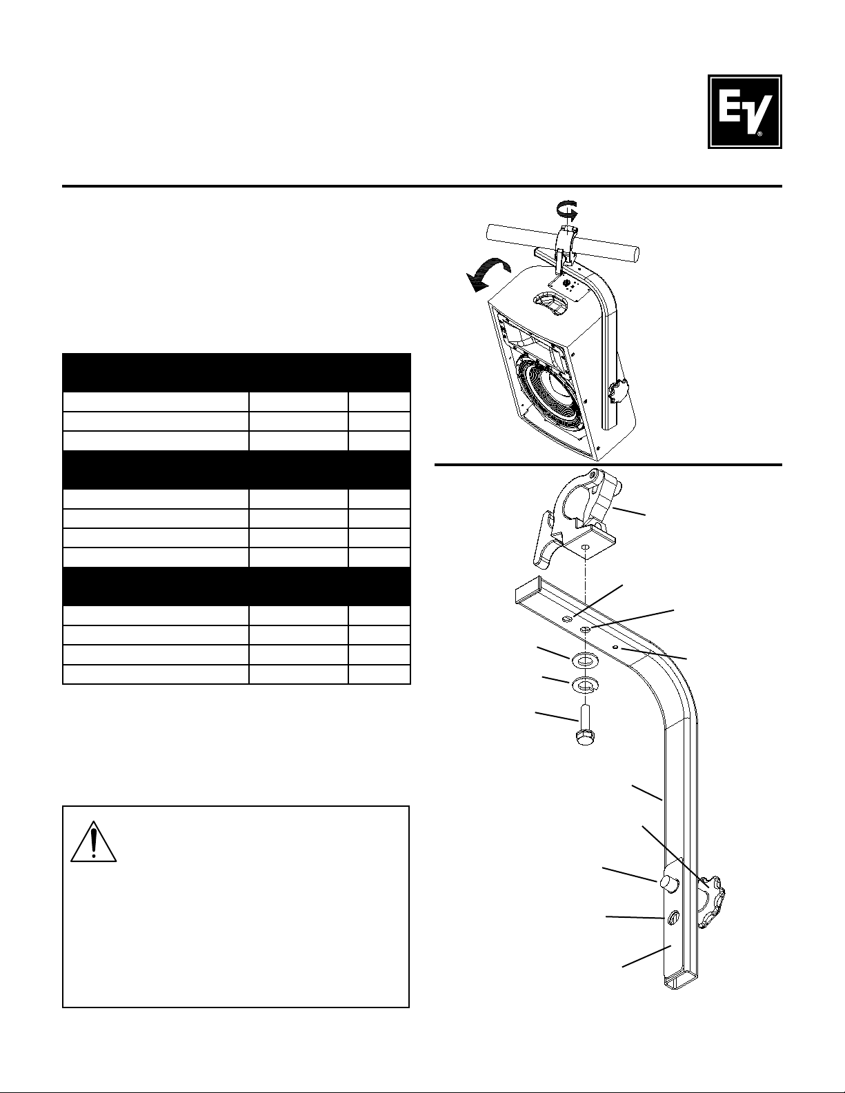
The Electro-Voice® TMK Truss Mount Kits are accessories that are designed to suspend Electro-Voice loudspeakers to a truss. The bracket allows the speaker to
be rotated in both the horizontal and vertical planes for
maximum versatility (see Figure 1). There are different
suspension kits, depending on the loudspeaker that is
being suspended, as shown in the table below:
TMK-PX Kit (Part Number KIT000006-001)
Used With: PX1122M, PX1152M, Plasma P1
Includes Model Part Number Quantity
TCA-1 Truss Clamp Adaptor ACC000012-001 1
VSA-1 Vertical Strong-Arm Mount ACC000007-001 1
TMK-ZX Kit (Part Number KIT000007-001)
Used With: ZX4, ZX5
Includes Model Part Number Quantity
TCA-1 Truss Clamp Adaptor ACC000012-001 1
VSA-1 Vertical Strong-Arm Mount ACC000007-001 1
HA-5 Handle Mount Adapter 301811-001 1
TMK-ZX3 Kit (Part Number KIT000023-001)
Used With: ZX3
Includes Model Part Number Quantity
TCA-1 Truss Clamp Adaptor ACC000012-001 1
VSA-1 Vertical Strong-Arm Mount ACC000007-001 1
HA-3 Handle Mount Adapter ACC000033-001 1
TMK Series
Truss Mount Kits
User Instructions
Washer
Lock Washer
Figure 1: Rotating and
Tilting Features of the
TMK Series Kits
TCA-1
Truss Clamp
Adaptor
Attachment
Point for all 15”
Loudspeakers
Attachment
Point for all 12”
Loudspeakers
Optional Safety
Point for M10
Eyebolt
Assembling TCA-1 to VSA-1 (all Speakers)
Remove the short 1/2” bolt and washer from TCA-1.
The short bolt and washer are not needed for installation. Mount the TCA-1 to VSA-1 in the desired horizontal position, using the long 1/2” bolt, flat washer, and
lockwasher (see Figure 2).
WARNING: Suspending any object is potentially dangerous and should only be attempted by individuals who
have a thorough knowledge of the techniques and regulations of rigging objects overhead. Electro-Voice® strongly
recommends that all speakers be suspended taking into
account all current national, federal, state and local regulations. It is the responsibility of the installer to ensure that all speakers are safely installed in accordance with all such regulations. When
speakers are suspended, Electro-Voice® strongly recommends that
the system be inspected at least once a year. If any sign of weakness
or damage is detected, remedial action should be taken immediately.
The user is responsible for making sure that the truss, and any additional hardware used, is capable of supporting the loudspeaker. Any
hardware used to suspend a loudspeaker that is not associated with
Electro-Voice® is the responsibility of others.
Bolt
VSA-1 Vertical
Strong-Arm
Mount
VSA-1 Handle
Attachment
Point for all 12”
Loudspeakers
Attachment
Point for all 15”
Loudspeakers
Friction Pad
Figure 2: Assembling the TCA-1 to the VSA-1
Page 2
Adjusting the Loudspeaker Attachment Point (all Speakers)
Move the threaded shaft to the correct hole by pulling back on the handle and sliding the shaft in the steel frame.
The upper point is used for 12” Loudspeakers and the lower point is used for 15” Loudspeakers (see Figure 3).
*Note: For ZX Series loudspeakers, attach the HA-3 or HA-5 adaptor to the loudspeaker before proceeding.
Top of
Assembly
Attachment
Point for all 12”
Loudspeakers
Attachment
Point for all 15”
Loudspeakers
Bottom of
Assembly
Figure 3: Adjusting the Loudspeaker Attachment Point on the VSA-1
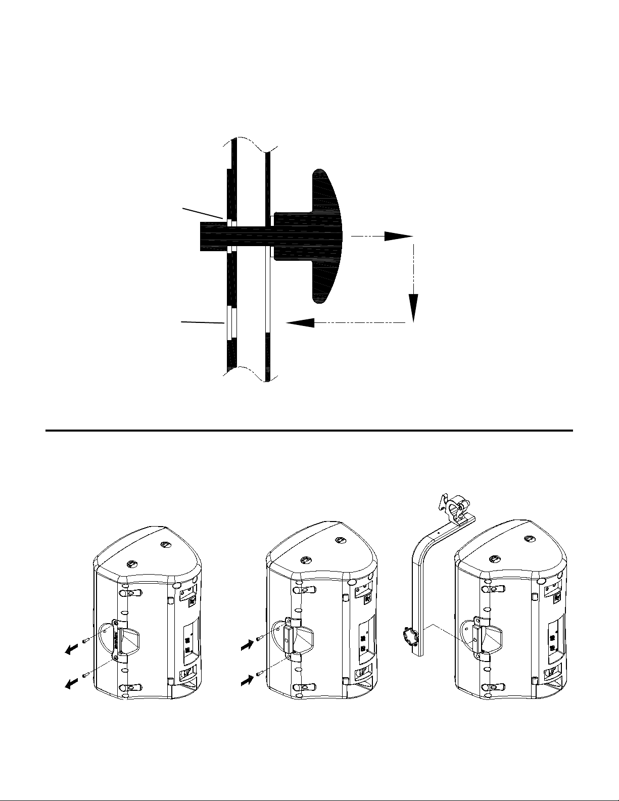
Installing the HA-3 or HA-5 (ZX-Series Loudspeakers Only)
Remove the M10 bolts that secure the handle to the loudspeaker, and fasten the HA-3 or HA-5 bracket in its place
(see Figure 4).
Figure 4a: Removing the
Bolts Securing the Handle
Figure 4b: Attaching the HA-3 or
HA-5 to the ZX Loudspeaker
Figure 4c: Attaching the VSA-1
to the HA-3 or HA-5 Handle Adaptor
Page 3

Attaching VSA-1 to Loudspeaker
(all Speakers)
Thread the VSA-1 to the loudspeaker by using the
threaded bracket (PX1122M, PX1152M, Plasma P1) or
HA-3 or HA-5 adaptor (ZX Series) on the right side of
the enclosure. Rotate the loudspeaker to the desired
vertical tilt position, and torque the threaded stud to
the enclosure using the handle (see Figure 5).
Optional: If local regulations
require an additional safety
point, attach an M10 shoulder
eyebolt (not included) to this
point on the VSA-1.
See Page 4 for required
safety points.
WARNING: The rubber pad acts as a locking mechanism for the threaded shaft. If enough torque is not
applied to the handle, vibrations from the loudspeaker
may loosen the shaft over time. The user should regularly inspect the shaft to ensure that the VSA-1 has not
loosened from the loudspeaker.
Figure 5a: Tightening the Attachment Point on
the VSA-1 to a PX-Series Loudspeaker
Figure 5b: Tightening the Attachment Point on
the VSA-1 to a ZX-Series Loudspeaker
Attaching Truss Mount and Speaker Assembly to Truss (all Speakers)
Loosen the clamping fixture on the TCA-1 and open the clamp. Attach the TCA-1 (including the strong arm and
loudspeaker) to the truss by sliding it past the clamping fixture. Adjust the clamp so it is behind the clamping
fixture, and tighten the handle (see Figure 6).
Clamping
Step 1 -
Close Clamp
Loosening
Step 1 -
Loosen T-Handle
Loosening
Step 2 -
Open Clamp
Clamping
Step 2 -
Tighten T-Handle
Figure 6a: Loosening Clamping
Feature on Truss Mount
Figure 6b: Attaching Truss Mount and
Loudspeaker Assembly to Truss
Page 4

Attaching Safety Point to Speaker
(PX1122M and PX1152M)
For PX1122M and PX1152M Only: Remove the M10
flat head bolt from the loudspeaker, and replace with
a forged steel shoulder eyebolt with a minimum safe
working load of 100 lbs. Attach a safety cable from the
eyebolt to the truss. The eyebolt and cable are not included with the accessory and are the responsibility of
the user. The cable should have no more than 2" of
slack (see Figure 7).
Truss
Single-Stud
Anchor
Fitting
Plasma P1
Loudspeaker
Truss
Eyebolt
PX1122M or
PX1152M
Loudspeaker
Figure 7: Attaching a Safety Point to a Phoenix
Series Loudspeaker
(VSA-1 Not Shown for Clarity)
Attaching Safety Point to Speaker (Plasma P1)
For Plasma P1 Only: Attach a single stud anchor fitting
with a minimum safe working load limit of 100 lbs. to the
top L-track. Connect a cable between the anchor fitting
and truss with a maximum of 2" of slack. The anchor fitting and cable are not included with the accessory and
are the responsibility of the user (see Figure 8).
Figure 8: Attaching a Safety Point to a Plasma
P1 Loudspeaker
(VSA-1 Not Shown for Clarity)
Attaching Safety Point to Speaker (ZX Series)
For ZX Series Only: Attach a single stud anchor fitting
with a minimum safe working load limit of 100 lbs. to the
top L-track. Connect a cable between the anchor fitting
and truss with a maximum of 2" of slack. The anchor fitting and cable are not included with the accessory and
are the responsibility of the user (see Figure 9).
Electro-Voice
12000 Portland Avenue South, Burnsville, MN 55337
Phone: 952/884-4051, Fax: 952/884-0043
www.electrovoice.com
© Bosch Communications Systems 03/2008
Part Number LIT000069 Rev B
®
Truss
Single-Stud
Anchor
Fitting
HA-3 or HA-5
Adaptor
ZX Series
Loudspeaker
Figure 9: Attaching a Safety Point to a ZX
Series Loudspeaker
(VSA-1 Not Shown for Clarity)
U.S.A. and Canada only. For customer orders, contact Customer Service at:
800/392-3497 Fax: 800/955-6831
Europe, Africa, and Middle East only. For customer orders, contact Customer Service at:
+ 49 9421-706 0 Fax: + 49 9421-706 265
Other Internatonal locations. For customer orders, Contact Customer Service at:
+ 1 952 884-4051 Fax: + 1 952 887-9212
For warranty repair or service information, contact the Service Repair department at:
800/685-2606
For technical assistance, contact Technical Support at: 866/78AUDIO
Specifications subject to change without notice.
 Loading...