

Page 1
Page 2

CLEAR SET-UP AND CONFIGURATION
Select amplifier type and activate through
"drag and drop."
Each amplifier is displayed showing address,
operation mode, input level, and network mode
(on-line/off-line). Double-click on one amplifier
link to the individual control panel for more
detail.
Amplifiers and channels may be assigned to
control groups on customized group control
panels with dedicated control parameters.
ADVANCED REMOTE CONTROL AND SUPERVISION
Amplifier Type: P900RL, P1200RL,
P3000RL, P900RT or P1200RT
Impedance Load Monitoring
Green = O.K.
Display red = Hi or Low
Threshold of DSP compressor
(yellow) and limiter (blue).
Temperature control
green = perfect, yellow = limit
red = too warm
Hi resolution input metering
Solo button: mutes all other
channels
MUTE button
Address number of amplifier
Name of amplifier (position, use,
loudspeaker group...)
Channel name (loudspeaker,
component, ...)
Display for protect mode
Display for dynamic limiter of amplifier
Hi resolution output metering in realtime. The yellow LED indicates 0dB for
maximum output power.
Level (attenuation) control of the
amplifier (infinity to 0dB).
Set-Up Button: accesses detailed
control of amplifier, including all
DSP functions (filter, delay,
dynamics)
POWER On/Off and operation
mode display
Monitor LED for stand-by mode
Page 3

STATE-OF-THE-ART SIGNAL PROCESSING WITH 24 FILTERS,
5 DELAYS , 2 COMPRESSORS AND 2 LIMITERS
Menu control for selection of DSP parameters, speaker assign,
impedance monitoring or protocol.
Each block of DSP functions shows the amount of active parameters.
Filter response, delay times and dynamic settings are displayed as a thumbnail.
The DSP functions are:
Master-EQ with five filters, each selectable as Low or Hi-Shelf,
Low or Hi-Pass, or PEQ.
Input-Delay for channel A, B and A+B, up to 1,000 ms.
Input-Routing (A, B, or A+B).
Channel-EQ with five filters as master EQ and additional all-pass
filter.
Crossover with Hi and Lo-Pass Filter
First to fourth order (Bessel, Butterworth, Linkwitz-Riley)
compressor and limiter per channel.
CLEAR OVERVIEW ON ALL DSP PARAMETERS AND FUNCTIONS
Channel-EQ with five filters.
Display of the filters and their acoustical
impact on the loudspeaker system.
Input-Delay for A, B, or sum A+B.
Maximum delay time 1,000 ms. Units:
µs, ms, s, cm, meters, inches, or feet.
Master EQ with five filters. Display of the
filter response and the acoustical impact
of each filter on the loudspeaker system.
Compressor and limiter per output.
Threshold assignable in volts or dBu.
Crossover with each Hi and Lo-Pass per
channel. Impact of all DSP parameters
(filters, delay , level) to acoustical delivery
of the system can be displayed.
Supervision for each connected loudspeaker with individual upper and lower
thresholds for impedance values. An outof-limit device will show up immediately.
Page 4

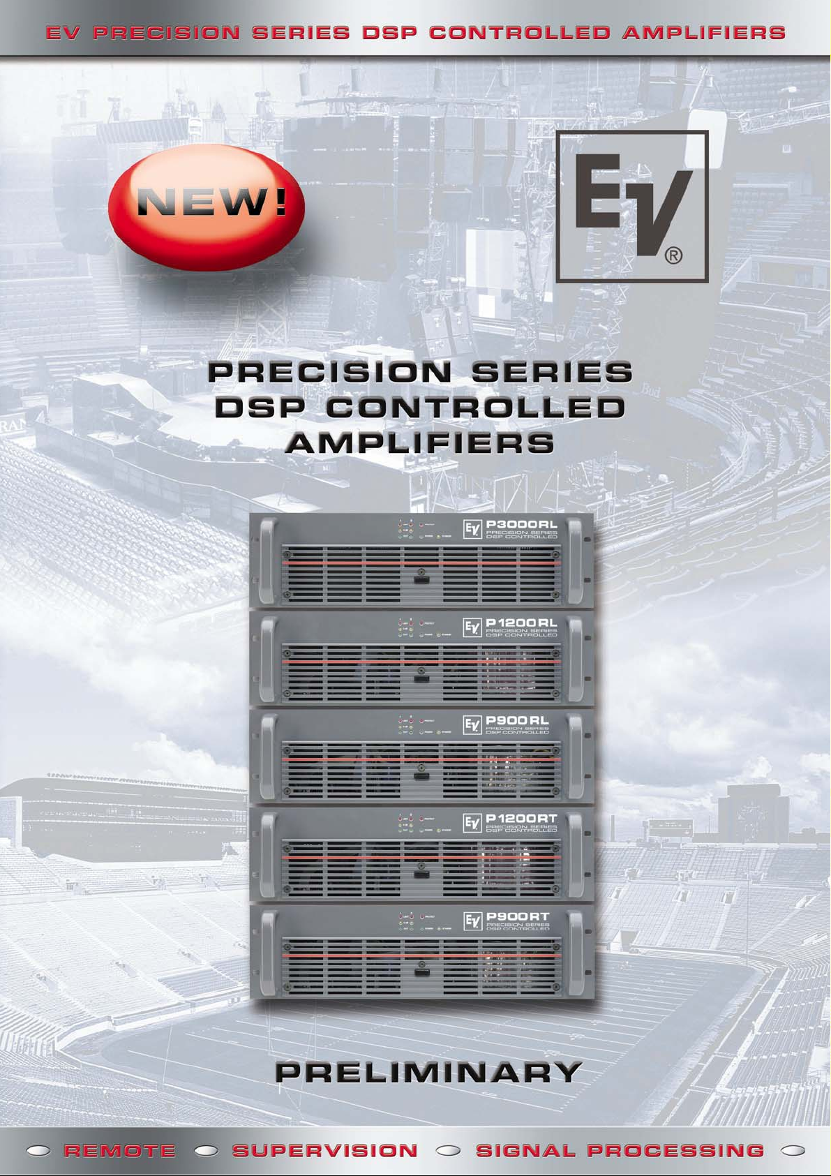
RANGE OF AMPLIFIERS FOR HIGH AND
LOW-IMPEDANCE APPLICATIONS
P3000 RL
The flagship, with 2 x 1300 watts into 4 ohms and 2 x 1800 watts into 2 ohms,
the digital controlled version of the legendary P3000 amplifier. Loudspeaker
outputs on Neutrik Speakon
P1200 RL
The universal with 2 x 600 watts into 4 ohms and 2 x 850 watts into 2 Ohms.
Loudspeaker ouputs on barrier strip.
P900 RL
Featuring 2 x 450 watts into 4 ohms and 2 x 650 watts into 2 ohms, the P900RL
is ideal for HF drive in multi-way systems. Loudspeaker outputs on barrier strip.
P1200 RT
High-impedance output for 100/70V-lines with 2 x 590 watts. The dynamic
limiter circuit includes the output transformer and limits THD to 1% maximum.
Loudspeaker outputs on barrier strip.
P900 RT
High-impedance output for 100/70V-lines with 2 x 410 watts.
Loudspeaker outputs on barrier strip.
®
NL4 connectors.
Rear panel view P1200 RL
Rear panel view P3000 RL
RCM-24: THE DIGITAL ENGINE WITH MORE THAN 114 dB DYNAMICS FOR
Remote Control
• Remote control of all amplifier parameters
• Centralized system configuration
• Preset and program change for different applications
• Control via one or multiple PCs with discretionary access
control
Signal Processing
• 12 filters, 2 delays, compressor and limiter per channel
• RACE Processed Presets for EV speakers available
Total Supervision
• All amplifier operation modes are controlled and monitored
• Automated action procedures on critical operation modes are
programmable
• Full time supervision of loudspeaker lines for short-circuit and
interrupt
• Full frequency bandwidth measurement of speaker impedance
and display of impedance curve showing tolerances
In and out jacks for CAN bus on RJ45 connectors—CAT-5 cabling
(includes audio monitoring signal) RS-232 interface to connect to
media control systems
Control port with GP in and out termination (0 to 5V) for external
control, free programmable functionality (i.e. integration into
safety and evacuation systems). Audio signal input on XLR
connector, parallel out and DSP out on Phoenix connector.
AD/DA-conversion in 24-bit resolution and 128-times
oversampling (linear phase); internal word length: 48-bit. This
allows the RCM-24 to offer a total dynamic in excess of 114 dB,
an unequalled value for digital signal processing in power
amplifiers.
Page 5

AUDIO PERFORMANCE, REMOTE CONTROL AND
SUPERVISION AT THE HIGHEST LEVEL
Electro-Voice is famous for its 75 years of experience in designing
and manufacturing loudspeakers and microphones. Many audio
professionals, however, don’t know that it also has 50 years of
design experience in power amplifiers and more than 20 years in
digital audio processing.
An unwavering commitment to satisfying customer needs made
Electro-Voice a leading manufacturer of sound reinforcement
systems for stadiums, arenas, multi-purpose venues, theatres and
cinemas around the globe. Due to their sonic purity and extreme
DSP CONTROLLED PRECISION SERIES AMPLIFIERS:
Remote control and supervision of up to 250
amplifiers via one or multiple PCs.
Central supervision of all amplifiers and connected
loudspeakers
State-of-the-art signal processing (Filter, Delay,
Level, Dynamics)
reliability, EV's amplifiers became established with top concertsound and professional installation projects worldwide. The
Precision Series is the flagship of EV's amplifier line. They employ
the highest levels of design to meet the highest levels of demand.
EV’s new DSP-Controlled P-Series amplifiers combine legendary
performance with uncompromised remote control and system
supervision capability. They use EV’s state-of-the-art signal
processor technologies, and they guarantee superior audio
performance.
Display of the acoustical response of EV
speakers in real-time (RACE)
Integration with life-safety systems and control
of external equipment
Exceptional audio performance and extreme
reliability
SYSTEM DESIGN AND CONFIGURATION
The network of the DSP Controlled Precision Series amplifiers is
controlled via a serial CAN-Bus. Up to 100 amplifiers, over a 1,000
m cable length can be controlled per CAN bus. USB to CAN
conversion is realized with the UCC-1 converter. Network cabling
is based on CAT-5 with RJ-45 connectors; each amplifier features
one input and one output. The audio monitor signal is available on
the XLR connector of the UCC-1.
Controlling more than 100 amplifiers requires another CAN bus.
At this time the control software is able to deal with a maximum
of 250 amplifiers in total. A significant advange of this architecture
is the ability to connect additional control PCs at any position in
the network. The software is able to handle several users, with
discretionary access control.
The DSP of each amplifier stores up to 8 user presets. This allows
system operation, independent of the network control in the
event of a network fault. All DSP settings (filter, eq, delay, level)
will stay in place. The other general-purpose amplifier inputs and
outputs may be used for network-independent preset switching.
For example, a dedicated emergency setting with maximum
power for the vocal band give a network of DSP-Controlled
Precision Series amplifiers the ability to meet highest security and
safety standards.
Page 6

SMALL SYSTEM CONFIGURATION — HOUSE OF WORSHIP
Switch panel (8 switches, 2 per amp)
RJ-45 CAN
bus (in)
RJ-45 CAN
bus (out)
To Amp 2
GP1 and GP2
connectors
NOTE: All amps link through CAN bus
MEDIUM SYSTEM CONFIGURATION — PERFORMING ARTS CENTER
Audio signal
Audio inputs
(from mixer)
Mixing Console
Congregation
Lobby
Audio signal
1
2
3
FRi152/64
4
FRi 2082
FFRi152/64
FRi 122/64
Crestron¤touch screen
RJ-45 CAN
bus (in)
RJ-45 CAN
bus (out)
To Amp 2
interface
Audio signal
RS-232
Audio inputs
(from mixer)
NOTE: All amps link through CAN bus
Mixing Console
Floor Balconies
Audio signal
1
FRi122/64
2
3
4
FRi122/64
Audio signal
5
6
7
8
9
10
11
EVID 4.2 (70/100V)
Audio signal
Dressing Rooms
12
Page 7

LARGE SYSTEM CONFIGURATION — ARENA
PC control station
UCC-1
converte4Fr
Audio signal
RJ-45 CAN
bus (in)
RJ-45 CAN
bus (out)
To Amp 2
NOTE: All amps link through CAN bus
Audio inputs
(from mixer)
¥ Up to 100 amplifiers per CAN bus
¥ Up to 250 amplifiers per system
¥ Up to 1000m per run
¥ Single run: No loop requirements
Mixing Console
Main PA
Sky boxes
Audio signal
Audio signal
1
2
3
4
5
6
13
14
15
16
17
18
Main PA
Sky boxes
7
8
9
10
11
12
FRi 122/64
19
20
21
22
23
24
Under-balcony fill
Sx300PI EVID 4.2 (70/100V)
19
20
21
22
23
24
19
20
21
22
23
24
Concessions area
19
20
21
22
23
24
19
20
21
22
23
24
Page 8

TECHNICAL DATA AND SPECIFICATIONS
Network and General Features
Maximum Configuration 100 amplifiers per CAN bus over a 1,000 meter cable run, 250 amplifiers in total
Supervised Amplifier Parameters Operation mode, temperature, pilot tone, protection mode status,
impedance of connected speaker system, output current and output voltage
Network Supervision Defective or missing amplifiers, limits, failure protocol
Audio Monitoring All input and output signals
System Back-Up Last setting stored initiated upon system activation
PC Control and Software Multiple PCs possible (discretionary access control), runs in MS Windows 95/98, 2000, NT, XP
Digital Signal Processing
A/D & D/A-converters 24 Bit, Sigma-Delta, 128x Oversampling, linear phase
Sampling Rate 48 kHz
Dynamic Range > 114 dB
I/O Structure 2 In - 2 Out, flexible routing (A, B, A+B)
Master (Input) EQ per Channel 5 filters selectable as PEQ (20 Hz - 20 kHz, Q: 0.4 - 20.0, +/-12 dB),
Lo-Shelf (20 Hz - 20 kHz, 6/12 dB slope, +/- 12 dB),
Hi-Shelf (20 Hz - 20 kHz, 6dB slope, +/-12 dB),
Hi-Pass and Low-Pass (20 Hz - 20 kHz, 6 dB/12 dB, Q: 0.4 - 2.0)
Master (Input) Delay For input A, B and A+B: 2 ms to 1,000 ms (unit:µs, ms, s, cm, m, inches, feet)
Channel (Output) EQ per Channel 5 filters selectable as PEQ (20 Hz - 20 kHz, Q: 0.4 - 20.0, +/-12 dB),
Lo-Shelf (20 Hz - 20 kHz, 6/12 dB slope, +/- 12 dB),
Hi-Shelf (20 Hz - 20 kHz, 6 dB slope, +/-12 dB),
Hi-Pass and Low-Pass (20 Hz - 20 kHz, 6 dB/12 dB, Q: 0.4 - 2.0);
All-Pass (20 Hz - 20 kHz, 1st/2nd Order,
Crossover per Channel Hi-Pass and Low-Pass each 6/12/18/24 Bessel / Butterworth, or 12/24 dB Linkwitz-Riley
Dynamics per Channel Compressor (Threshold, Attack, Release, Ratio) and Limiter (Threshold, Release)
Other Parameters Polarity (inverted/non-inverted), Level, Mute (On/Off)
Amplifier P900 RL P1200 RL P3000 RL P900 RT P1200 RT
8Ω 4Ω 2Ω 8Ω 4Ω 2Ω 8Ω 4Ω 2Ω 100V 70 V 100V 70 V
Continous Output Power (1 kHz, THD 1%) 280 W 450 W 650 W 380 W 600 W 850 W 850 W 1300 W 1800 W 410 W 400 W 590 W 580 W
Rated Output Power (20 Hz-20 kHz, THD <0,2%) 230 W 350 W 450 W 300 W 500 W 650 W 750 W 1200 W 1500 W 350 W 350 W 500 W 500 W
Maximum Bridged Output (1 kHz, THD 1%) 900 W 1300 W - 1200 w 1700 W - 2600 W 3600 W - - - - THD @ Rated Output Power < 0,05% <0,1% <0,2% <0,1% <0,2%
DIM 30 <0,03% <0,01% <0,2% <0,3% <0,2% <0,3%
Intermodulation (SMPTE) <0,08% <0,01% <0,1% <0,3% <0,1% <0,3%
Signal to Noise Ratio > 105 dB >100 dB
Frequency Response (-1 dB) 20 Hz - 20 kHz 45 Hz - 20 kHz
Dynamic Audio Limiter THD </= 1% (Input signal </= + 20 dBu
Protections Hi-Temperature, DC, HF, Back EMF, Peak Current Limiter, Inrush Current Liminter, Power On Delay
Cooling 3(4)-stage fan, front-to-rear cooling
Input Sensivity and Impedance 1,55 V (+6dBu), 20 kOhm, XLR Input
Maximum Input Level 8,7 V (+21 dBu)
Serial Interface Network: CAN, 2 RJ45 (CAT-5 Cabling), RS-232 for media control systems
Control Logic in and Outputs 2 x 0V 5V free configurable, Easy-Remote
Loudspeaker Connectors Barrier Strip Neutrik Speakon NL4 Barrier Strip
Dimensions (Width x Height x Depth) 483 mm x 132,5 mm x 390 mm (19”, 3 U)
Net Weight 16 kg 17 kg 30 kg 24 kg 25 kg
All measurements both channels driven into 8 ohms unless other specified.
USA Telex Communications Inc., 12000 Portland Ave. South, Burnsville, MN 55337, Phone: +1 952-884-4051, FAX: +1 952-884-0043
Germany Telex EVI Audio, Hirschberger Ring 45, D 94315, Straubing, Germany, Phone: 49 9421-706 0, FAX: 49 9421-706 265
U.K. Shuttle Sound Ltd., The Willows Centre, Willow Lane, Mitcham CR44NX, Surrey • Phone: +44 20 864 671 14, FAX: +44 20 864 075 83
France EVI France S. A., Parc de Courcerin, Allee Lech Walesa, Lognes, F-77185 Marne La Vallee, France, Phone: 33/1-6480-0090, FAX: 33/1-6006-5103
Australia EVI Audio (Austl.), Unit 23, Block C, Slough Business Estate, Silverwater N.S.W. 2128, Australia, Phone: 61/2-9648-3455, FAX: 61/2-9648-5585
Hong Kong EVI Audio Limited, Unit E & F, 21/F, Luk Hop Industrial Bldg., 8 Luk Hop St., San Po Kong, Kowloon, Hong Kong, Phone: 852-2351-3628, FAX: 852-2351-3329
Japan EVI Audio Japan, Ltd.,5-3-8 Funabashi, Setagaya-ku, Tokyo, 156-0055 Japan, Phone: 81-3-5316-5020, FAX: 81-3-5316-5031
Singapore Telex Communications, 3015A Ubi Rd 1, 05-10, Kampong Ubi Industrial Estate, Singapore 408705, Phone: 65-746-8760, FAX: 65-746-1206
Africa Mid-East Telex EVI Audio, Hirschberger Ring 45, D 94302, Straubing, Germany, Phone: 49 9421-706 0, FAX: 49 9421-706 265
Latin America Telex Communications Inc., 12000 Portland Ave. South, Burnsville, MN 55337, Phone: +1 507 526 3205, FAX: +1 507 526 3059
Copyright 2002 Telex Communications, Inc. The information in this brochure is preliminary. Telex Communications, Inc. reserves the right to change without prior notice. PA 20559
© 2002 Telex Communications, Inc. • 12000 Portland Avenue South • Burnsville, MN 55337 • All information subject to change without notice.
 Loading...