

Page 1
Key Features:
• Free-standing weighted base for reliable stability.
• Accepts T elex & Electro-Voice bodypack
transmitters (RE-1, RE-2, FMR-1000, FMR 500 &
Safe-1000)
• Easy to use mute switch. Can be programmed to
operate as either latching on/off or momentary
push-to-mute.
• High visibility blue LED clearly displays mic
status to the user.
• Exceptional sound quality with EV’s proven
PolarChoice design.
• Selectable polar pattern to easily adapt to any
situation. Choose between omni, cardioid, supercardioid or hypercardioid.
• Consistent microphone voicing across all four
patterns.
• Available in three gooseneck lengths: 18", 12" or
5".
• Wireless system sold separately
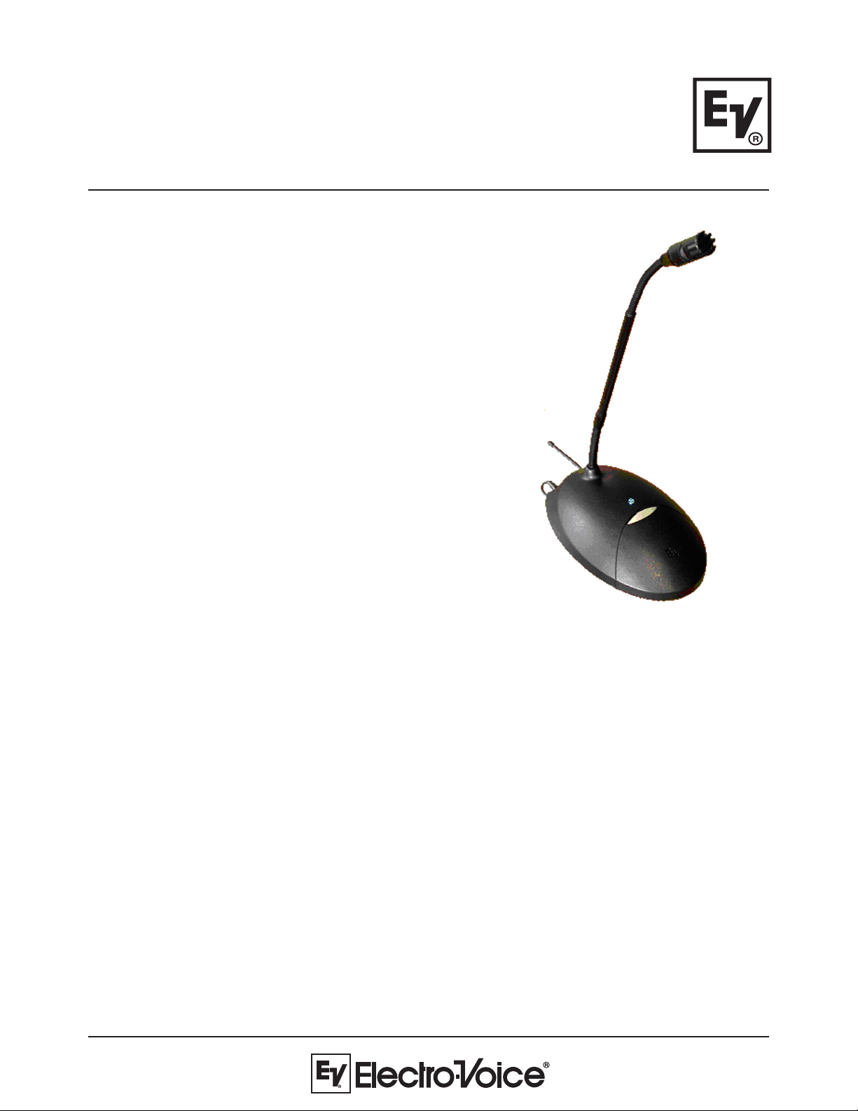
PolarChoice Satellite
PC Sat-5/PC Sat-12/
PC Sat-18
Multi-Pattern Wireless
Free-Standing Microphone
General Description:
The PolarChoice Satellite is a free-standing gooseneck style microphone, firmly anchored in place
by its elegantly designed base. This low-profile foundation hides PolarChoice Satellites most powerful feature - space for a wireless transmitter. Turn the base over to reveal the specially designed
compartment for housing a Telex or Electro-Voice bodypack transmitter. Connect the microphone to
the bodypack, set-up the wireless channel, and place PC Satellite anywhere an easy-to-use microphone is required. No longer do you have to cut holes in tables, run long cables, or compromise the
architectural integrity of an installation. With the Polar Choice Satellite, anything is possible.
The PC-Satellite features an EV PolarChoice multi-pattern microphone. The multi-pattern versatility
of the PolarChoice microphone makes it a true problem solver. With one non-directional and 3
directional polar patterns available, the PolarChoice microphone is ideal for virtually any installation.
The PC-Satellite also includes a switchable high pass filter that greatly reduces any vibration induced
noise pick-up.
Page 2
PolarChoice PC Sat-5/ PC Sat-12/ PC Sat-18 Microphones
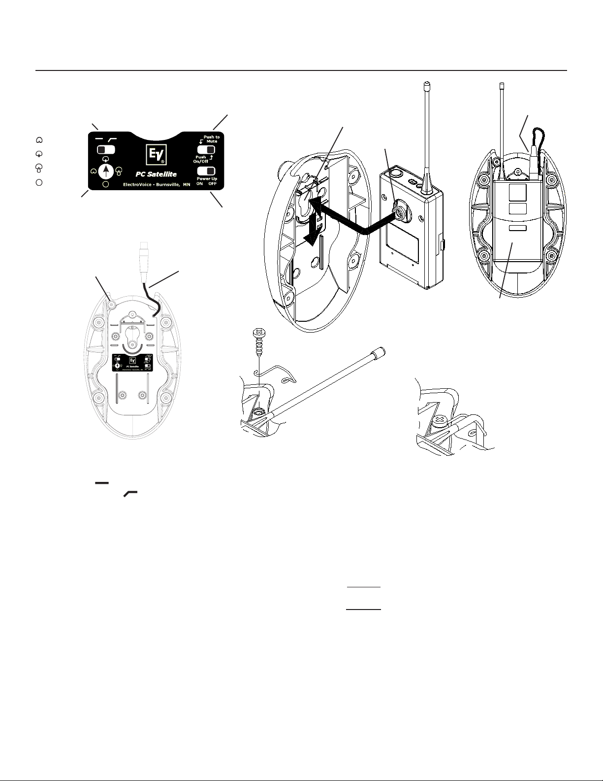
Microphone Setup:
A. Hi
Pass
Select
Cardioid
Supercardioid
Hypercardioid
Omnidirectional
C. Push
Button Mode
Select
Base
Opening
Bodypack
Button
TA4F
Connector
B. Polar
Pattern
Select
Antenna Guide
Attach Boss
Figure 2:
Bottom View
Figure 1: PC Satellite Controls
TA4F
Cable
D. Power
Up Mode
Select
Figure 3: Installation of
Bodypack Transmitter
Figure 5: Antenna
Guide Installation
Bodypack Transmitter
Battery Door
Figure 4: Bottom View
with Bodypack
Transmitter
Figure 6: Orientation
of Antenna with
Antenna Guide
1) A. Select High-Pass switch position (see figure 1).
Flat ( ): Normal response.
High Pass ( ): minimum 5 dB reduction in sensitivity at 100 Hz.
B. Select preferred polar pattern (see figure 1).
C. Pushbutton Mode Select (see figure 1) -
Push to Mute: In this mode, the audio output of the microphone is disabled (muted) when button is depressed.
Microphone resumes normal function when button is released.
Push On/Off: In this mode, the audio output of the microphone is disabled when the pushbutton is depressed and
released. The microphone resumes normal function when the button is depressed and released again.
D. Power Up Mode Select (see figure 1) - This mode only functions when control (C) is set to Push On/Off.
Power Up On: In this mode, audio output of the microphone is enabled when power from the bodypack transmitter
is applied.
Power Up Off: In this mode, audio output of the microphone is disabled when power from the bodypack
transmitter is applied.
2) Note: bodypack transmitter must have the bodypack button installed on the back of its housing. The bodypack does
not ship with this part attached.
3) Insert bodypack into Satellite (see figure 3). Bodypack button inserts into opening on bottom plate. Push bodypack
into plate, and slide down as shown.
4) Carefully insert TA4F connector into bodypack (see figure 4).
5) Turn on bodypack transmitter & check for mic level.
6) Test mic in actual use situation, and set audio gain on bodypack transmitter for optimal gain through wireless system.
Note: battery door may be opened to access gain adjustment in bodypack, without removing bodypack from base (see
figure 4).
7) If desired, install antenna guide using screw provided (see figure 5). First drive in screw completely, then back it out
slightly, hook on antenna guide and screw it down. Orient antenna within guide to achieve vertical antenna polarization
(see figure 6).
Page 3

Engineering Data Sheet
Applications:
The PolarChoice PC Sat is acoustically designed for high-quality sound reinforcement and broadcast applications. The
frequency response is tailored for wide-range sound reproduction with very natural sound pick-up for either distant or closeup use. The PolarChoice PC Satellite can be used on lecterns, podiums, desks, table-tops, or other applications. To
maximize gain-before-feedback, the PolarChoices three directional polar patterns allow the user to pick the directional
polar pattern for optimum effect. For those applications where gain-before-feedback is not a problem, an omnidirectional
pattern is included. Applications requiring speaking close to the microphone at podiums, lecterns, or pulpits normally
require a windscreen (included) to control breath noise and P-popping or, in some cases, wind noise from circulating air.
Technical Specifications:
Generation Element:
Dual condenser, back electret
Frequency Response:
50 Hz to 20,000 Hz (see chart)
Polar Patterns: (see chart)
Omnidirectional
Cardioid
Supercardioid
Hypercardioid
Switches and Controls:
Top mounted momentary push-button
Push on/off, or push-to-mute selector
Power up on/off selector
High-pass enable
4-position polar pattern selector
Sensitivity, Open Circuit Voltage, 1 kHz:
17.8mV/Pascal
Clipping Level (1% THD):
>130 dB SPL
Equivalent Noise:
<32 dB SPL A weighted
(0 dB=20 micropascals)
Dynamic Range: >98 dB
Output Impedance, 1 kHz:
1000 ohms
Power Requirements:
5 VDC, supplied by beltpack
Current Consumption:
<1.5 mA
Polarity:
Pin 2 positive, referenced to pin 1,
with positive pressure on the diaphragm
Dimensions:
Base (all mics):
Length: 175 mm (6.9 in.)
Width: 117 mm (4.6 in.)
Height: 56 mm (2.2 in.)
Gooseneck Length:
PC Satellite-5: 114 mm (4.5 in.)
PC Satellite-12: 318 mm (12.5 in.)
PC Satellite-18: 470 mm (18.5 in.)
Maximum Head Diameter:
14.6 mm (0.58 in.)
Gooseneck Diameter:
Lower section, 7.9 mm (0.31 in.)
Upper section, 6.4 mm (0.25 in.)
Accessories Furnished:
Windscreen
Antenna Guide & Mounting Screw
Color:
Nonreflecting black
Environmental Conditions,
Relative Humidity 0-50%:
-29° to 74°C (-20° to 165°F)
Relative Humidity 0 to 95%:
-29° to 57°C (-20° to 135°F)
Net Weight:
PC Satellite-5: 458 grams (16.2 oz)
PC Satellite-12: 614 grams (21.7 oz)
PC Satellite-18: 631 grams (22.3 oz)
EV Multi-Port Windscreen:
All PolarChoice microphones come with the exclusive EV
Multi-Port Windscreen. This unique one-piece ported design
offers greatly improved resistance to P-popping noise by
creating a two-stage filter that has an air space between the
stages. This makes the multi-port windscreen as effective
as much larger traditional designs.
Dimension Drawings:
Page 4

Frequency Response: Polar Response:
Architectural & Engineering Specs:
PolarChoice Satellite: PC Sat-5, PC Sat-12, PC Sat-18
The microphone shall be a free-standing, wireless, table-top microphone. The base will have an integral 4-pin TA4F connector, which
interfaces directly to one of the following wireless microphone bodypack transmitters: Electro-Voice RE-1 or RE-2, Telex FMR-1000, FMR-500
or Safe-1000. The microphone shall have four selectable polar patterns: omnidirectional, cardioid, supercardioid, and hypercardioid. The mic
element is a back-electret condenser type with a frequency response of 50 Hz to 20 kHz. The microphone shall have a nominal, balanced
output impedance of 200 ohms. The microphone will have a switchable high pass filter to roll off low frequencies. The microphone shall have
an output level of 17.8 mV/Pascal, and outputs shall not be appreciably affected by the following temperature and humidity extremes: -29° to
74° C (-20° to 165°F) when the relative humidity is 0-50%; -29° to 57°C (-20° to 135°F) when the relative humidity is 0-95%. Dimensions shall
be 170 mm (6.7 in.) long (PC Sat-5), 373 mm (14.7 in.) long (PC Sat-12), and 526 mm (20.7 in.) long (PC Sat-18) with a maximum head
diameter of 14.6 mm (0.58 in). The PC Sat-5 microphone shall include a 114 mm (4.5 in.) gooseneck. The PC Sat-12 microphone shall include
a 318 mm (12.5 in.) gooseneck. The PC Sat-18 microphone shall include a 470 mm (18.5 in.) gooseneck. The gooseneck will be attached to a
base that has a top mounted push-button, and a status LED that lights when audio is active. The push-button will be configurable for push
on/off, or push-to-mute operation. Furthermore, when the push-button is set for push on/off operation, the status of the microphone when
power is initially applied, can be programmed to be either on or off. All controls except for the push button are accessible from the bottom of
the microphone base, when the bodypack is not installed. The microphone base shall be of metal construction. The microphone will include
an external windscreen and antenna guide. The microphone shall have a nonreflecting black finish. The Electro-Voice PolarChoice™ PC Sat5, PC Sat-12, or PC Sat-18 is specified.
12000 Portland Avenue South, Burnsville, MN 55337
Phone: 952/884-4051, Fax: 952/884-0043
www.electrovoice.com
© Telex Communications, Inc. 10/2003
Part Number 38110-31 1 Rev . A
noitamrofnIgniredrO
.oNledoM.oNtraPnoitpircseD
5-taSCP000-384103htgneLkcenesooG"5
21-taSCP000-484103htgneLkcenesooG"21
81-taSCP000-584103htgneLkcenesooG"81
U.S.A. and Canada only. For customer orders, contact Customer Service at:
800/392-3497 Fax: 800/955-6831
Europe, Africa, and Middle East only. For customer orders, contact Customer Service at:
+ 49 9421-706 0 Fax: + 49 9421-706 265
Other International locations. For customer orders, contact Customer Service at:
+ 1 952 884-4051 Fax: + 1 952 736-4212
For warranty repair or service information, contact the Service Repair department at:
800/553-5992 or 402/467-5321
For technical assistance, contact Technical Support at: 800/392-3497 or 952/736-4656
Specifications subject to change without notice.
 Loading...