

Page 1
Key Features:
• Selectable polar pattern to easily adapt
to different acoustic environments.
Choose between omni, cardioid,
supercardioid or figure 8.
• Exceptional sound quality with EV’s
proven PolarChoice design.
• Consistent microphone voicing across
all four patterns.
• Easy to use mute switch. Can be
programmed to operate as either latching
on/off or momentary push-to-mute /
push-to-talk.
• Disassembly of the mic isn’t required to
change switch functions or for use with
automatic mixers.
• Compatible with echo cancellation for
conference applications.
• High visibility blue LED clearly displays
mic status to the user and can be
remotely controlled in automatic mixer
mode.
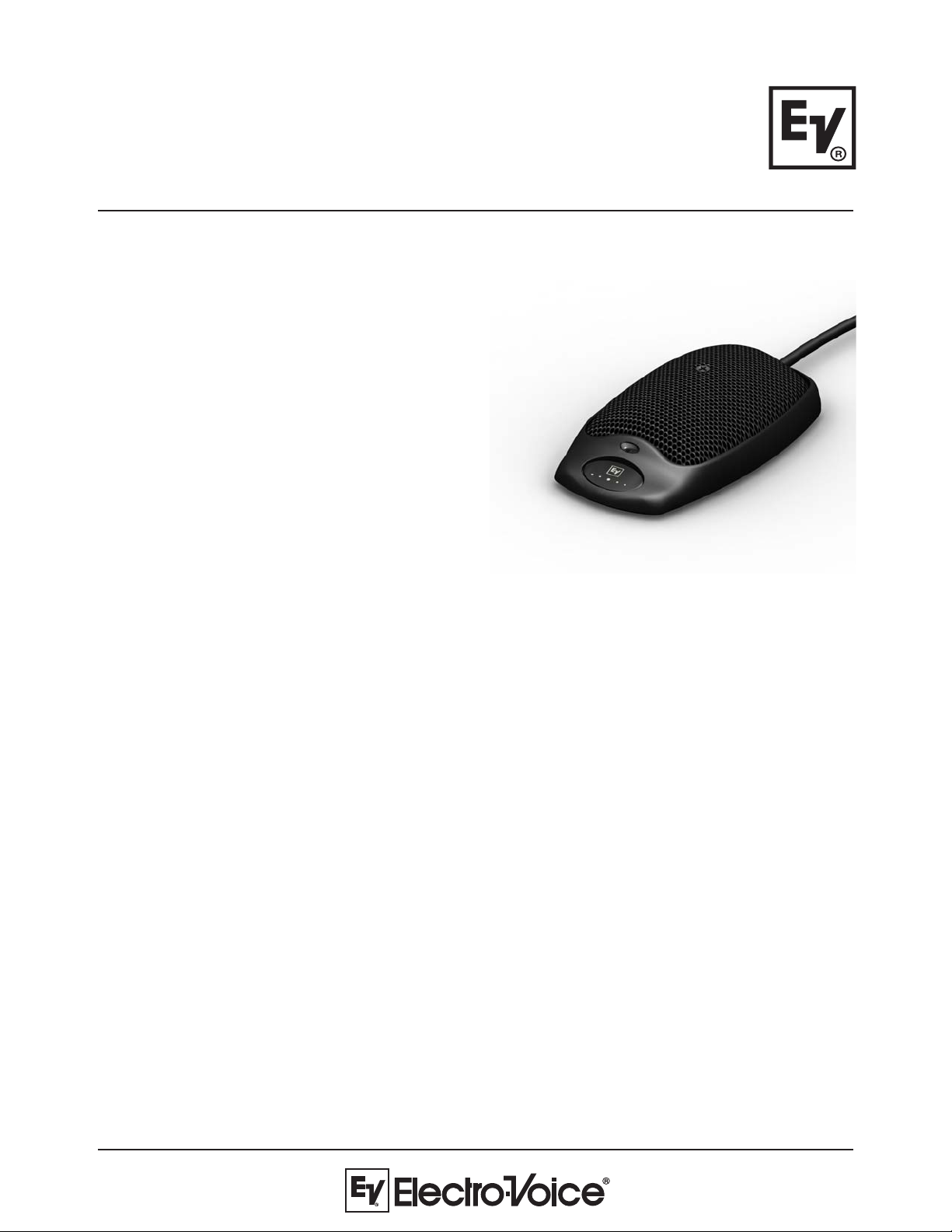
PolarChoice Series:
PC Boundary
Multi-Pattern
Boundary Microphone
General Description:
The PC Boundary mic is a low profile microphone that can be used with standard and automatic mic mixers. The PC
Boundary mic is a member of the EV PolarChoice™ series of multi-pattern microphones. The multi-pattern versatility
of the PolarChoice™ microphone makes it a true “problem solver”. With one non-directional and three directional
polar patterns available, PolarChoice™ microphones are ideal for virtually any installation. Of particular interest is the
figure 8 pattern that allows miking people on opposite sides of a table with only one microphone, while providing a
dramatic reduction of ambient room noise.
The PC Boundary mic features a large soft-touch mute button. The mute button can be configured for push-on /
pushoff, push-to-talk, or push-to-mute functions. Mute switch programming is easily accomplished without
disassembling the microphone. The microphone can also be programmed to be either live or muted when power is
initially applied (when in toggle mode). Additionally, a switch on the bottom of the mic, quickly converts the PC
Boundary to automatic mixer mode. In this mode, audio is always on.
A large blue LED indicator lights when the mic is active, and can be remotely controlled when the mic is in automatic
mixer mode.
The PC Boundary mic is designed to take acoustic advantage of placing a microphone close to a “boundary” such as
conference table. Advantages include reduced phase cancellation and up to 3dB reduction in ambient noise.
The PC Boundary mic also includes a switchable high pass filter and a high-performance vibration-damping pad on
the bottom to greatly reduce any vibration induced noise pick-up.
Page 2
PC Boundary
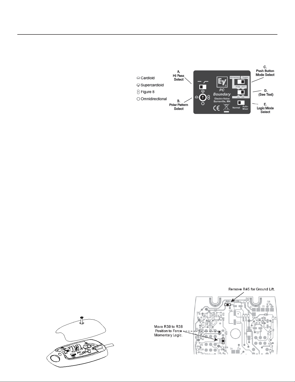
Switch Setting Guide:
Audio (Switches A & B)
A – Hi Pass Filter
Start with this switch set to the left (flat response). If the mic
is in a location where low frequency rumble or wind noise is
encountered, moving this switch to the right will help by
reducing low frequency sensitivity.
B – Polar Pattern
The cardioid polar pattern works well for most installations. If
feedback from a sound system occurs, switching to the
supercardioid pattern will usually allow increased mic gain
before feedback. The figure 8 pattern can be used to mic two
people sitting on opposite sides of a table, potentially reducing
the total number of mics required. The omnidirectional pattern
is best suited for situations where there is no sound
reinforcement system present, such as for recording.
Mute Switch Configuration (Switches C & D)
(The membrane switch on the top of the PC Boundary microphone.)
Momentary modes:
When switch “C” is set to the left, the mute switch action is momentary. (If switch “D” is in the left hand position, the mic will be in push-to-mute
mode. If switch “D” is in the right hand position, the mic will be in push-to-talk mode.)
Figure 1:
Mic Switch Interface
Toggle Modes:
When switch “C” is in the right hand position, the mute switch will be in toggle (push-on / push-off) mode. (When the mic is in this mode, the
setting of switch “D” determines if the mic audio should be muted when power is first applied. If switch “D” is in the right hand position, the mic
audio will be muted when power is first applied. If switch “D” is in the left hand position, mic audio will be on when power is first applied.)
Logic Mode Select (Switch E)
When switch “E” is set to the left, the PC Boundary operates as a normal microphone. Mic muting and operation of the LED is controlled by the
pushbutton on the top of the mic.
When switch “E” is set to the right hand position, the mic will be in automatic mixer mode, and the following will apply:
Logic Signals
Logic signal cable hookup guide:
If the PC Boundary mic is in momentary mode (see above section on the mute switch), the logic level on the white wire will normally be “high”, and
go “low” when the mute button is pressed. If the mute switch is set for toggle mode, the logic will toggle from high to low, or from low to high,
each time the button is pressed. (If desired, a pc board change can be done to force the logic to always be momentary, regardless of switch
settings. See diagram.)
LED Control
When the mic is in automatic mixer mode, a low logic signal on the
orange LED control wire will cause the LED to light.
Logic Ground Lift
If necessary, the logic and audio grounds can be separated. This
requires removing a resistor from the pc board. See diagram.
1) Mic audio is always on.
2) The automatic mixer controls LED operation.
Green – Logic Ground
White – Switch Logic
Orange – LED Control
Remove the center
screw and grille to
access the pc
board.
Figure 2:
PCB Access
Figure 3:
PCB Jumper Locations
Page 3

Engineering Data Sheet
Applications:
The PC Boundary is acoustically designed for high-quality sound reinforcement and broadcast applications. The frequency
response is tailored for wide-range sound reproduction with very natural sound pick-up. The PC Boundary microphone’s three
directional polar patterns allow the user to pick the directional polar pattern for optimum effect. For those applications where
gain-before-feedback is not a problem, an omnidirectional pattern is included. The PC Boundary microphone is ideal for
boardrooms, conference tables, or anywhere a high quality low profile microphone is required.
Technical Specifications:
Generation Element:
Dual condenser, back electret
Frequency Response:
50 Hz to 20,000 Hz (see chart)
Polar Patterns: (see chart)
Omnidirectional
Cardioid
Supercardioid
Figure 8
Switches and Controls:
Top mounted momentary membrane switch
Automix, normal selector
Push on/off, or push-to-mute selector
Power up on/off selector
High-pass enable
4-position polar pattern selector
Sensitivity, Open Circuit Voltage, 1 kHz:
31.5mV/Pascal
Clipping Level (1% THD):
>115 dB SPL
Equivalent Noise:
29 dB SPL “A” weighted typical
(0 dB=20 micropascals)
Dynamic Range:
>86 dB
Output Impedance, 1 kHz:
200 ohms
Power Requirements:
Phantom, 12 – 52 VDC
Current Consumption:
< 8 mA with P12 supply
Cable:
10-foot, 5-conductor (2-conductor shielded) black
cable, terminated with a professional 3-pin male XLR
style connector with gold plated pins.
Polarity:
Pin 2 positive, referenced to pin 3,with positive
pressure on the diaphragm
Dimensions:
1 10.4mm (4.34") long
164.6mm (2.54") wide
25.8mm (1.02") high
Weight:
269 grams (9.5 oz), including cable
Dimension Drawings:
Page 4

Frequency Response: Polar Response:
Architectural & Engineering Specs:
PC Boundary
The microphone shall be a low profile boundary microphone. The microphone will have a 10-foot integral 5-conductor , 2conductor shielded cable terminated in a 3-pin XLRM connector. The microphone shall have four select able polar
patterns: omnidirectional, cardioid, supercardioid, and figure 8. The mic will use a pair of back-electret condenser
elements with a frequency response of 50 Hz to 20 kHz. The microphone shall have a nominal, balanced output
impedance of 200 ohms. The microphone will have a switchable high-pass filter to roll off low frequencies. The
microphone shall have an output level of 5.6 mV/Pascal and outputs shall not be appreciably affected by the following
temperature and humidity extremes: -29° to 74° C (-20° to 165°F) when the relative humidity is 0-50%; -29° to 57°C (20° to 135°F) when the relative humidity is 0-95%. Dimensions shall be 1 10.4 mm (4.34 in.) long by 64.6mm (2.54 in.)
wide by 25.8mm (1.02 in.) high. The microphone will feature a top mounted membrane switch and a status LED that
lights when audio is active. The membrane switch will be configurable to operate in either momentary or toggle mode.
When the microphone is set in momentary mode, the membrane switch can be programmed to operate in either pushto-mute or push-to-talk mode. When the microphone is set in toggle mode and power is initially applied, the status of
the microphone can be programmed to be either on or muted. The microphone will be capable of operation with
automatic mixers by means of a configuration switch located on the bottom of the microphone. When the microphone
is in automatic mixer mode, normal LED and top push button functions are disabled. In automatic mixer mode, audio
will always be on, the top push button will only change the logic level on the microphone’s white wire, and a logic low
level on the microphone’s orange wire will cause the LED to illuminate. All controls except for the push button shall be
accessible from the bottom of the microphone base. The microphone base
and grille shall be of metal construction. The microphone shall have a
nonreflecting black finish. The Electro-Voice PC Boundary microphone is
specified.
.oNledoM.oNtraP
yradnuoBCP000-390000DRP
noitamrofnIgniredrO
12000 Portland Avenue South, Burnsville, MN 55337
Phone: 952/884-4051, Fax: 952/884-0043
www.electro voice.com
© Telex Communications, Inc. 6/2007
Part Number LIT000111 Rev . B
U.S.A. and Canada only. For customer orders, contact Customer Service at:
800/392-3497 Fax: 800/955-6831
Europe, Africa, and Middle East only. For customer orders, contact Customer Service at:
+ 49 9421-706 0 Fax: + 49 9421-706 265
Other International locations. For customer orders, contact Customer Service at:
+ 1 952 884-4051 Fax: + 1 952 736-4212
For warranty repair or service information, contact the Service Repair department at:
800/553-5992 or 402/467-5321
For technical assistance, contact Technical Support at: 800/392-3497 or 952/736-4656
Specifications subject to change without notice.
 Loading...