

Page 1

OWNER‘S MANUAL
Page 2

2
3
3
4
5
5
6
7
7
7
CONTROL PORT
8
ADDRESS
8
8
9
9
OUTPUT VOLTAGE CONFIGURATION
GROUND-LIFT SWITCH
CABLING
CAN-BUS
SPECIFICATIONS / TECHNISCHE DATEN
32
34
35
36
WICHTIGE SICHERHEITSHINWEISE
WICHTIGE SERVICEHINWEISE
20
AUSPACKEN & GARANTIE
INSTALLATIONSHINWEISE
22
23
23
23
23
CONTROL PORT
23
ADDRESS
25
25
26
GROUND-LIFT SCHALTER
26
26
VERKABELUNG
27
28
CAN-BUS
30
30
31
SPECIFICATIONS / TECHNISCHE DATEN
32
34
35
ABMESSUNGEN
36
Page 3
3
The lightning ash with arrowhead symbol, within an
equilateral triangle is intended to alert the user to the
the product’s enclosure that may be of suf cient
The exclamation point within an equilateral
triangle is intended to alert the user to
the presence of important operating and
2.
3.
4.
5.
ensure that no objects lled with liquids, such as vases, are placed on this apparatus.
6.
Clean only with a dry cloth.
7.
8.
9.
Only use attachments/accessories speci ed by the manufacturer.
damaged in any way, such as power-supply cord or plug is damaged, liquid has been spilled or
objects have fallen into the apparatus, the apparatus has been exposed to rain or moisture, does not
operate normally, or has been dropped
To completely disconnect mains power from this apparatus, the power supply cord must be
CAUTION:
These servicing instructions are for use by quali ed personnel only. To reduce
the risk of electric shock, do not perform any servicing other than that ontained
to quali ed service personnel.
2.
opened, needs to be operated and is connected to the mains
3.
4.
The minimum distance between parts carrying mains voltage and any accessible metal piece (metal
enclosure), respectively between the mains poles has to be 3 mm and needs to be minded at all times.
The minimum distance between parts carrying mains voltage and any switches or breakers that are not
connected to the mains (secondary parts) has to be 6 mm and needs to be minded at all times.
5.
only rmissible when using original parts.
6.
Altering the circuitry without prior consent or advice is not legitimate.
7.
Any work security regulations that are applicable at the location where the appliance is being serviced
8.
All instructions concerning the handling of MOS - circuits have to be observed.
SAFETY COMPONENT ( MUST BE REPLACED BY ORIGINAL PART )
grounding prong. The wide blade or the third prong are provided for your safety. When the provided plug does not
t into your outlet, consult an electrican for replacement of the absolete outlet.
Page 4
4
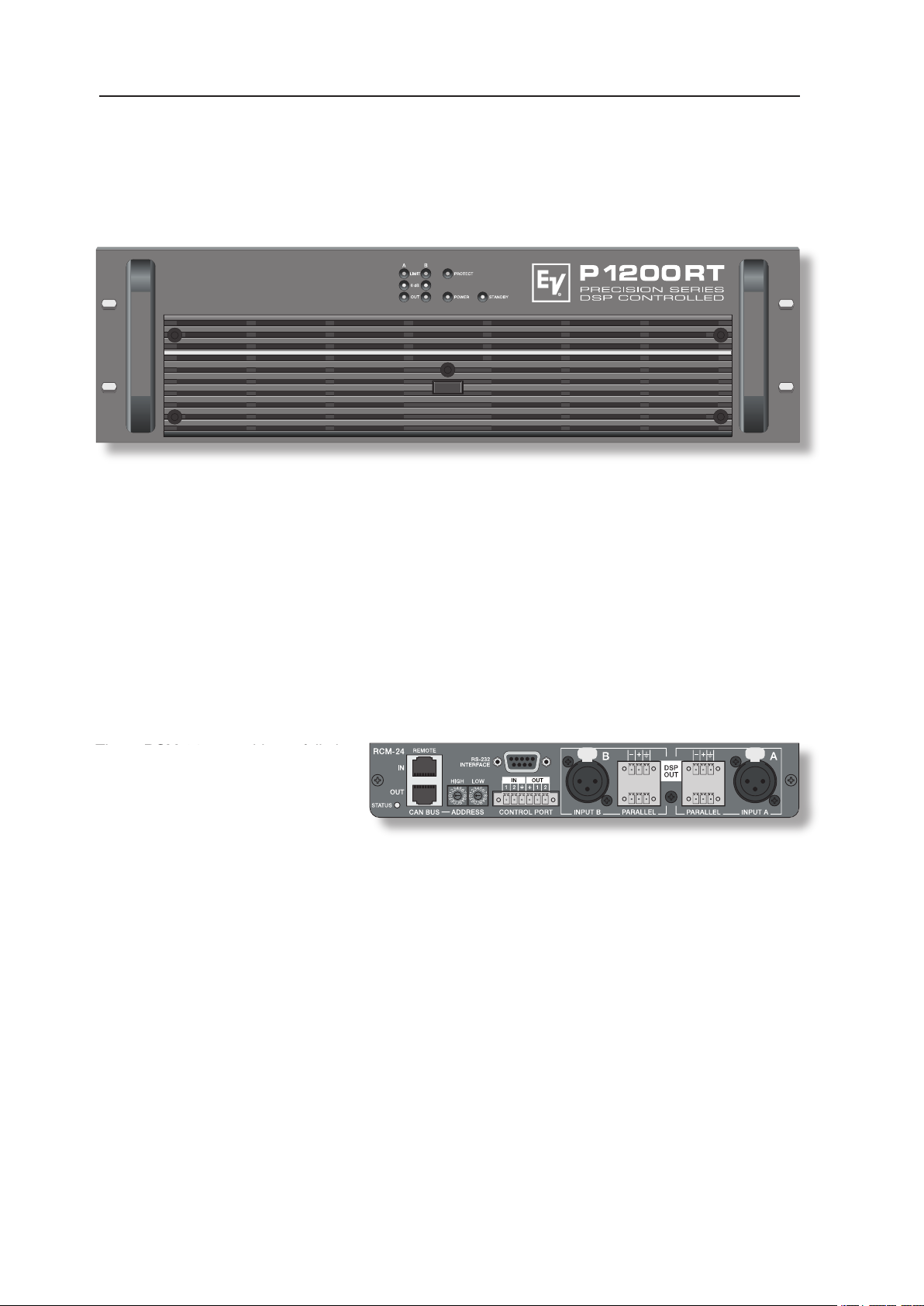
Congratulations!
With buying an Electro-Voice PRECISION SERIES power ampli er you have chosen
an appliance that employs the most advanced technology.
stability. Each power ampli er employs an RCM-24 Remote Control module allowing centralized
con guration, control and monitoring of all relevant power amp parameters (like output current, output
voltage, load impedance, etc.).
The power ampli ers employ two high-performance output transformers each and offer oating
The gapless protection circuitry concept not only prevents the power amp itself but also the connected
and of course Thermal Overload Protection for the output transistors and mains transformers.
Three-speed high performance fans guarantee outstanding thermal stability at absolute low running
Comprehensively dimensioned power supply units with low-leakage toroidal transformers provide
extensive headroom far above the stated nominal power.
The RCM-24 provides full-size
overview of the system’s entire status
and control over all rele vant system
Control Network consisting of up to 250 power amps. The Windows Software IRIS – Intelligent Remote &
the opportunity to take speci c measures prior to the occurrence of critical operational states. Programming
an automatic response for exceeding or falling below speci c limits is possible as well. All parameters,
e.g. power-on/off, levels, muting, lters, etc. can be controlled in real-time and saved in any power amp
and –voltages of the two power ampli er channels. Each time the signal falls below or exceeds set
checking the connected loudspeaker systems. The integrated signal generator is employed together
with the current/voltage testing to measure the connected loudspeakers’ and cable’s impedance
Comparing the measured impedance progression to a reference value is possible at all times, which
allows recognizing even the slightest loudspeaker defects or irregularities.
Page 5
5
stored in the module’s 8 user presets. Independent from network control all DSP-settings ( lter, delay,
for network-independent switching to another preset (e.g. alarm settings with maximum energy for voice
and text announcements). Therefore, P-Series amps with RCM-24 modules installed ful l even the
When designing the RCM-24, uncompromising audio quality was the highest maxim. AD/DA-conversion
value for digital audio appliances.
All con guration, control and monitoring details of P-Series power amps are explained in the
documentation accompanying the PC Windows software IRIS.
Carefully open the packaging and take out the power ampli er. Next to the power ampli er itself, the
screw-on connectors (1x 2-pole, 4x 3-pole, 1x 6-pole) plus a set of rack shelf mounting adapters. Please
only a completely lled in warranty certi cate entitles you to stake any warranty claims. The appliance
comes with a 36 months warranty, starting with the date when receiving the good from your dealer.
system make sure to provide suf cient ventilation. Leave a gap of at least 60mm x 330mm (up to the
cabinet’s top ventilation louvers) for air circulation between the rear of the power ampli er and the
cabinet’s/rack’s rear wall. Make sure to leave at least 100mm of space above the cabinet or rack shelf
system. Since the temperature inside of the cabinet or rack shelf system can easily rise up to 40°C
during operation, bearing in mind the maximally allowable environmental temperature during operation
for all other appliances installed in the same rack shelf system is mandatory. (also refer to “MAINS
OPERATION & RESULTING TEMPERATURE”)
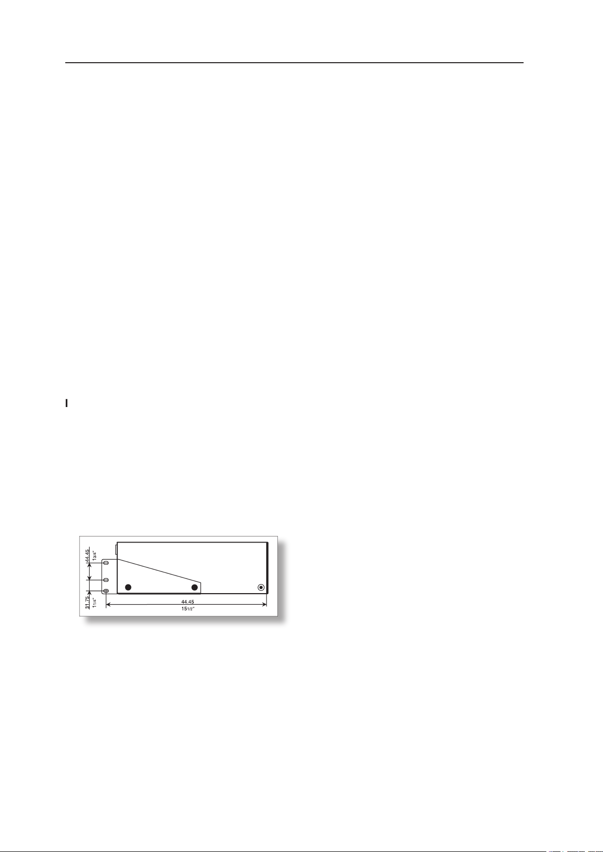
The use of rails or optionally available rack
adapters – NRS 90235 (112733) – is
appliance in a rack shelf system to prevent
the front panel from bending.
Caution:
temperature or +40°C is not permissible.
The power ampli er has to be protected against: dripping or splashing water, direct sunlight, high
temperatures or direct in uence of heat sources, high humidity, extensive dust and vibrations.
Condensation on internal parts may occur after transporting the power ampli er from a cold into a
warmer environment. In that case operation is only permissible after the appliance has gained the
ampli er’s enclosure make sure to instantly separate the appliance from the mains power and contact
an authorised DYNACORD service centre for inspection before continuing operation.
surface of the enclosure or lead to dangerous re hazard.
44.45
1/2
Page 6
6
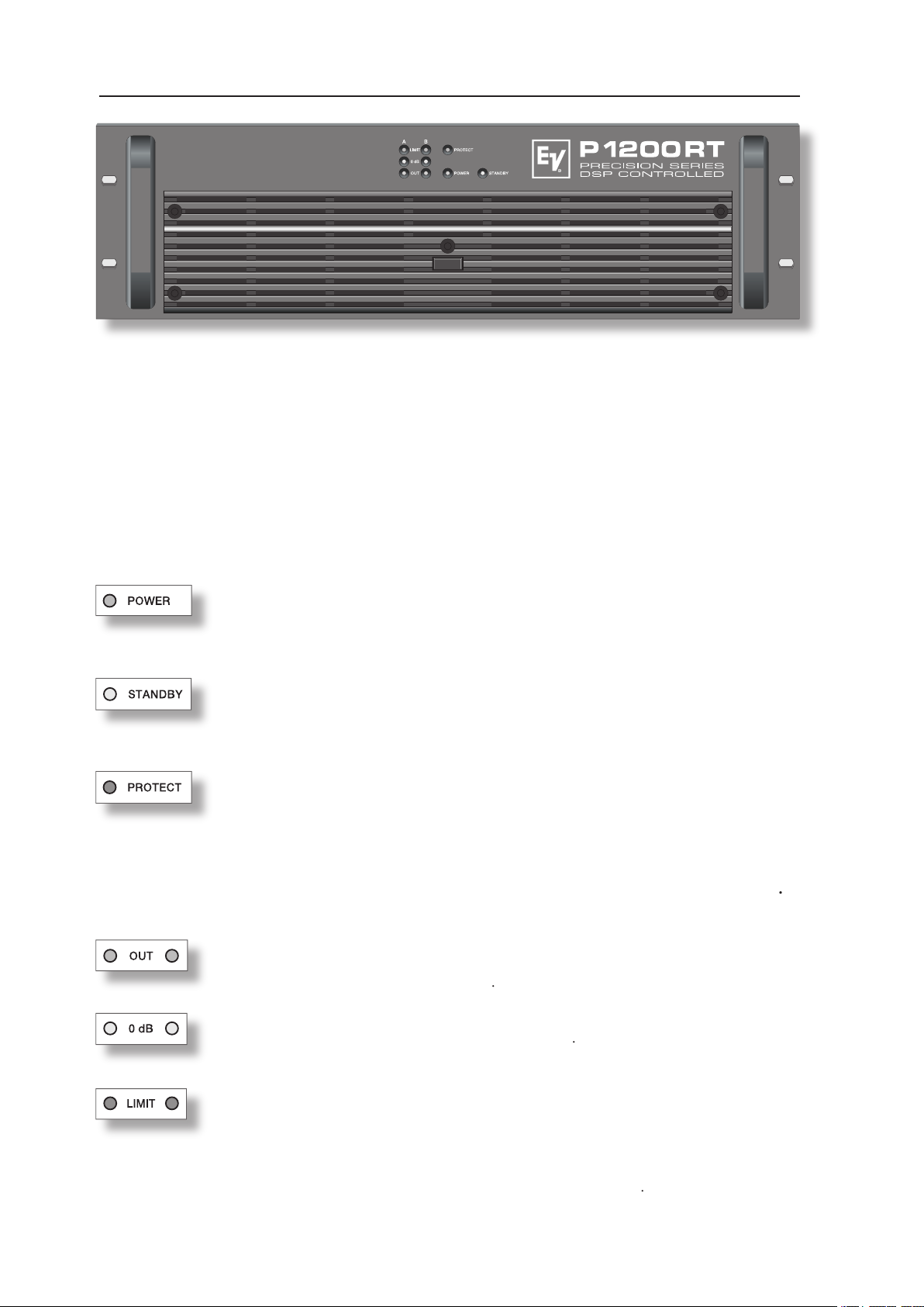
This indicator lights when the power ampli er has been switched on. Causes for
the POWER-indicator not lighting are: the appliance is not connected to the mains
This indicator light when the power ampli er is in stand-by mode, which can be
activated from the RCM-24 or via Easy Remote. In stand-by operation only the
separated from the mains.
The PROTECT LED lights indicating that one of the internal protection circuits
against thermal overload, short-circuit, Back-EMF, HF-occurrence at the output, etc.,
the load connected to prevent the connected loudspeaker systems and the power
ampli ers as well from being damaged. Whatever caused the fault – e.g. a short-
circuited speaker cable –
.
The OUT LED lights as soon as an audio signal of approximately 30dB below full
or a protection circuit has been activated
The 0dB LED lights when the power ampli er is driven at its maximum. Higher input
voltage does not result in higher peak output voltage
This indicator lights as soon as the integrated dynamic limiter is activated and the
to +21dBu down to a S/N-ratio of approximately 1%. If, on the other hand, this LED
systems connected from being damaged by probable overload
on. The soft-start function prevents current inrush peaks on the mains, which in addition prevents
the mains line protection switch from activating during power-on operation of the power ampli er.
The loudspeaker outputs are activated via relay switching with a delay of approximately 2 seconds
effectively attenuating eventual power-on noise. The PROTECT LED lights during the delay time and
the fans run at maximum speed. This is normal to con rm the immaculate operation of the protection
circuitry. Upon power-on, all power amps with RCM-24 Module installed regain the state of operation
Page 7
7
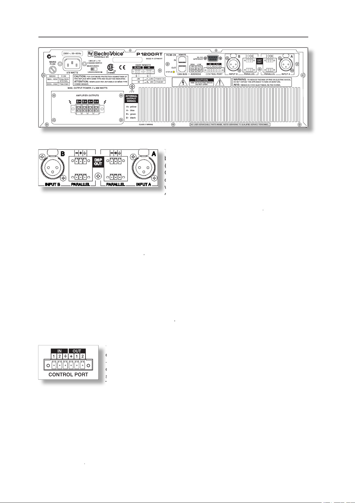
The inputs INPUT A & INPUT B are electronically
of the XLR-type input connectors is according to the
Connection can be established via the XLR-type input connectors INPUT A / INPUT B or the supplied
screw-on connectors which are connected in parallel. In addition, using the PARALLEL-connectors
without the need for extra splitter-cables
The DSP output signal – i.e. the post-digital-signal-processing-unit audio signal – is present at the
correspondingly ampli ed present at the power amp’s main outputs.
The DSP OUT can be utilized for feeding the digitally processed audio signal from the RCM-24 Remote
Control Module to additional power ampli ers (without DSP-module); e.g. for increasing the overall out-
electronically balanced. Output impedance is
100
Ω
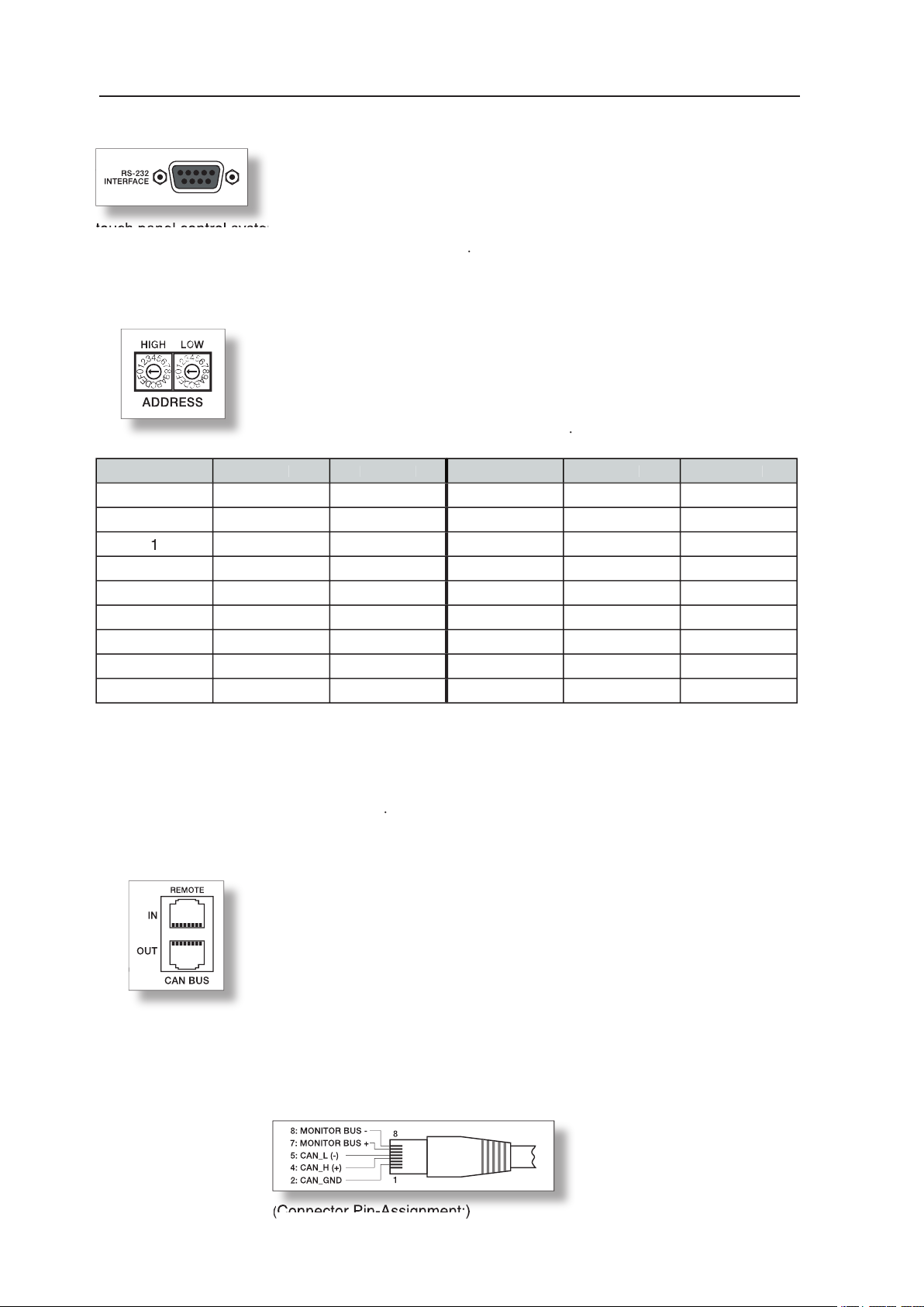
The CONTROL PORT offers two freely programmable control inputs and
external switches, pushbuttons or relays.
The two control outputs OUT1 / OUT2 are carried out as Open Collector Outputs. In non-active state
The outputs serve for signalling internal operational states. They can be used for the direct triggering
of LEDs, indication lights or relays. The +5V reference connector provides power supply for externally
connected appliances with amperage of maximally 100mA. The control outputs allow signal indication
of operational states (critical temperature, exceeding or decline of de ned limit values, faults, etc.) at
central operator desks or to other systems ( re alarm system, general alert system) even without PC.
the IRIS software
The CONTROL PORT offers two freely programmable control inputs and
control outputs as well as the reference connections for ground potential and
+5V. Using the PC Windows software IRIS, the control inputs can be
con gured and serve for instance for Power-On / Stand-by switching, preset
switching or parameter control.
The two control contacts IN1 / IN2 are internally set to +5V (open) via pull-up
The inputs INPUT A & INPUT B are electronically
Connection can be established via the XLR-type input
connectors or the supplied screw-on connectors,
which are connected in parallel. The pin-assignment
Page 8
8
The RS-232 interface is for connecting media control systems as
well
as building management systems providing control and monitoring of all
touch panel control systems. For a programmer’s guide and complete protocol description, please refer
to the documentation accompanying the IRIS software
ADDRESS
The address selection switch allows setting the ampli er’s network address,
which, within a CAN-network, can range from 01 to 250 (FA hex). Caution:
con icts might occur. Address setting has to be performed in hexadecimal
code. The selection switch LOW represents the low-value digit while the
Adress-Table:
Adress
Adress
008
0 ... F
090 ... F
0 ... F
A
0 ... F
2
0 ... F
32 ... 47
0 ... F
3
0 ... F
48 ... 63
C
0 ... F
4
0 ... F
64 ... 79
0 ... F
208 ... 223
5
0 ... F
80 ... 95
0 ... F
224 ... 239
6
0 ... F
96 ... 111
0 ... A
240 ... 250
7
0 ... F
Address 0 (00 hex, factory-pre-set) ensures that the ampli er is separated from the remote
communication, so that it does not appear in the system set-up even though it might be connected to
the CAN-bus. When the ampli er is powered-on with its address set to “0”, all internal parameters are set
to “0” respectively to bypass and the routing is set to 2-in-2. In that case the ampli er behaves absolutely
The sockets are parallel connected and serve as input as well as for
connecting through of the Remote network. Common RJ-45 patch cables
can be used for rack-shelf cabling. The CAN-bus needs to be terminated at
Detailed guidelines concerning cabling and bus length are provided in the
chapter “REMOTE CONTROL NETWORK”.
+6dBu (1.55V) while the maximum output level is +21dBu (8.7V).
Connector Pin-Assignment:
Connector Pin-Assignment:
)
Page 9
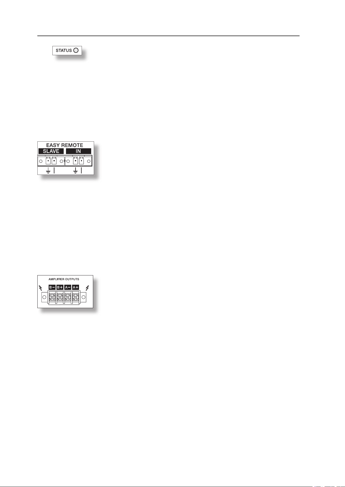
EASY REMOTE
Easy Remote provides a simple way to remotely power-on/off the power
amplier. The Easy Remote function is only useful for appliances not
employing a RCM-24 Module. Controlling appliances with RCM-24 Module
installed per Easy Remote is practically pointless.
EASY REMOTE IN
Leaving the pins of the EASY REMOTE IN socket open, i.e. when connecting +5V, the appliance power
is switched on. When connecting the EASY REMOTE IN, i.e. when feeding 0V from the control output,
the appliance enters standby mode.
EASY REMOTE SLAVE
The EASY REMOTE SLAVE connector provides connection for additional appliances with Easy-Remote
function (e.g. for switching several devices within a rack-shelf ON/OFF).
The switching of the slave-units is delayed to prevent the mains fuses from blowing.
POWER AMPLIFIER OUTPUTS
REAR VIEW
The STATUS LED provides optical indication of CAN-bus trafc. When the
power amplier’s address is set to “00” so that it is separated from the CAN bus, the STATUS LED blinks every 3 seconds.
As soon as CAN-bus communication is recognized, the LED is activated
for at least 100ms whenever the power amplier actively sends data on the
CAN-bus.
The STATUS LED may also be activated from the PC. In this case, the LED
of the according power amplier blinks fast and steady while all other status LEDs within the system stay dimmed.
4-pole binding-post terminals are provided for the power amplier channels „A“
and „B“. Two integrated audio output transformers convert the power amp’s
nominal output voltage to 100V or 70V respectively. Depending on the conguration, the corresponding output voltage is present at the oating output
terminals.
The maximum amount of connected loudspeaker systems is reached when the
loudspeaker network’s total power consumption equals the power amplier’s
nominal output capacity, without exceeding the power amp’s nominal load impedance.
For further information on nominal output capacity and nominal load impedance, please refer to the
“SPECIFICATIONS”.
Caution: During operation the binding-post terminals might carry high voltages. Therefore, installing
the loudspeaker network has to be in accordance with applicable safety regulations.
Installation has to be carried out by accordingly trained professionals only.
When installing and operating 100V PA-systems obeying the VDE-regulation DIN VDE
0800 is mandatory.
Especially when 100V alarm PA-system installations are concerned, safety measures have
to be in accordance with rating class 3. Before operating the power amplier closing the
coverlid attached to the terminal strip is mandatory.
9
Page 10
OUTPUT VOLTAGE CONFIGURATION
The power ampli er’s output voltage is factory pre-set to the corresponding voltage setting for
takes only little effort.
220V, 230V, 240V
70V Output Voltage
Caution:
Opening the appliance is necessary to recon gure the output voltage setting.
Therefore, only trained personnel may perform recon guration.
- Remove all screws securing the cover plate.
- Remove the plastic screw in the top plate.
- Open the appliance by removing the cover.
- On the printed board assembly 86276:
for 100V output voltage: close the bridge R56
for 70V output voltage: open the bridge R56
- Proceed in reverse order to reassemble the appliance.
The ground-lift switch allows eliminating noise loops. If the power ampli er
switch to its GROUNDED position is recommended. If the power ampli er
the switch to its UNGROUNDED position is recommended
type with identical amperage, voltage and blow characteristics. If the mains
fuse blows more often, please contact an authorized service centre.
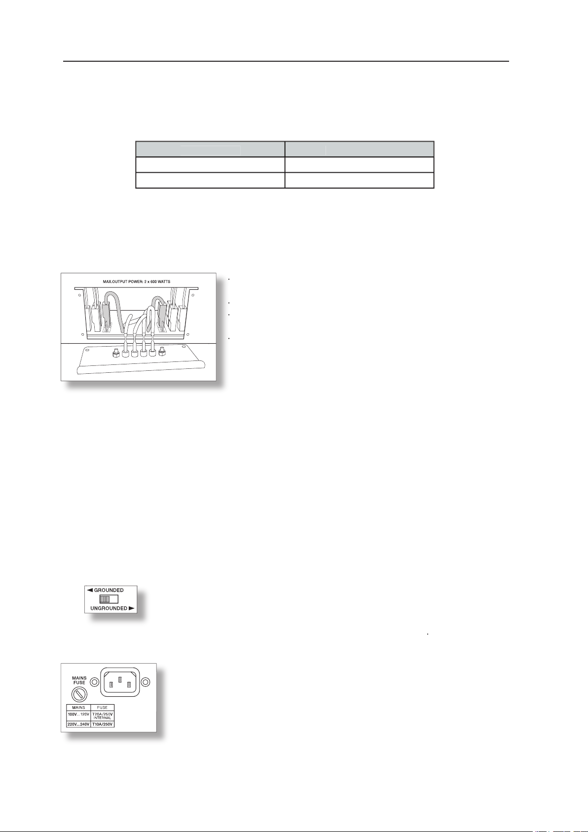
- Disconnect any cables connected to the appliance; especially
the mains cord.
- Remove all xing screws of the output connectors panel.
- Pull out the panel by holding it at the terminal strips
(see diagram).
- The connector pins 100V and 70V are for selecting the desired
output voltage for channel A (right channel) & B (left channel).
output voltage for channel A (right channel) & B (left channel).
- Change the output voltage by pulling the corresponding
connector (grey shaded in the diagram) and inserting it to the
connector (grey shaded in the diagram) and inserting it to the
connector pin for the desired voltage setting.
connector pin for the desired voltage setting.
- The diagram shows the con guration with both channels set
to 70V.
Page 11
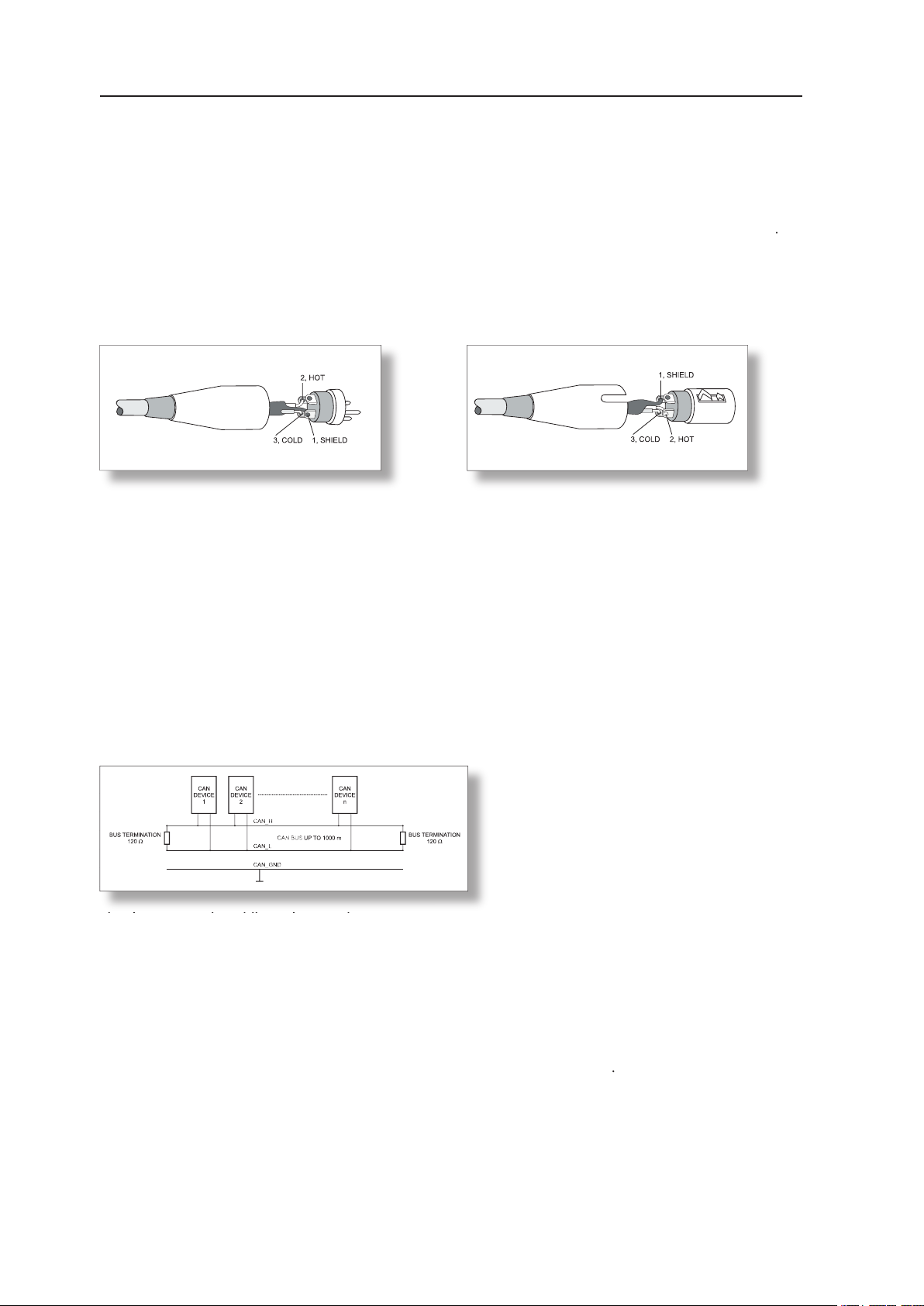
Choosing balanced cables (two conductors for the audio signal plus separate shielding mesh) with
XLR-type connectors is recommended for LF-signal connection. Although connecting unbalanced
cables to the power ampli er inputs is possible as well, using balanced cabling is always preferable. A
great number of today’s audio appliances employ balanced outputs. With balanced cabling, the shield
connects all metal enclosure parts and thus ef ciently eliminates the introduction of noise and hum
XLR-type connector pin-assignment
XLR (male)
XLR (female)
The network of the remote power amps is based on the CAN-bus standard, which for years is especially
for command and data transmission. Controlling the power ampli ers is performed from a PC with IRIS
– Intelligent Remote & Integrated Supervision – software installed. The UCC1 USB-CAN Converter
serves as interface between the PC and the CAN-bus. Connecting up to 100 power ampli ers per CAN-
for controlling more than 100 power amps while the IRIS software allows administering a total of 250
The network topology used by the CAN-bus is based on the so-called “bus or line topology”, i.e. all
the cabling running from one participant on the bus to the next, allowing unlimited communication among
all appliances. In general, it does not matter whether a participant on the bus is a power ampli er
or an UCC1 USB-CAN converter, so that
can be operated on a single CAN-bus. Since
the CAN-interfaces of all appliances are
galvanically separated from the rest of the
circuitry, network cabling also carries a common ground conductor (CAN_GND) ensuring that all
CAN-interfaces in the network are connected to a common ground potential. The UCC1 provides the
are connected in parallel to serve as input and output (for connecting through) for the data transfer within
the remote-network. The CAN-bus has to be terminated at both ends using 120
terminator plugs, two
of which – CAN-TERM 120
Ω
– are supplied with the UCC1. Connect one of these to the RJ-45 socket
of the rst and the other to the socket of the last appliance on the CAN-bus
Page 12
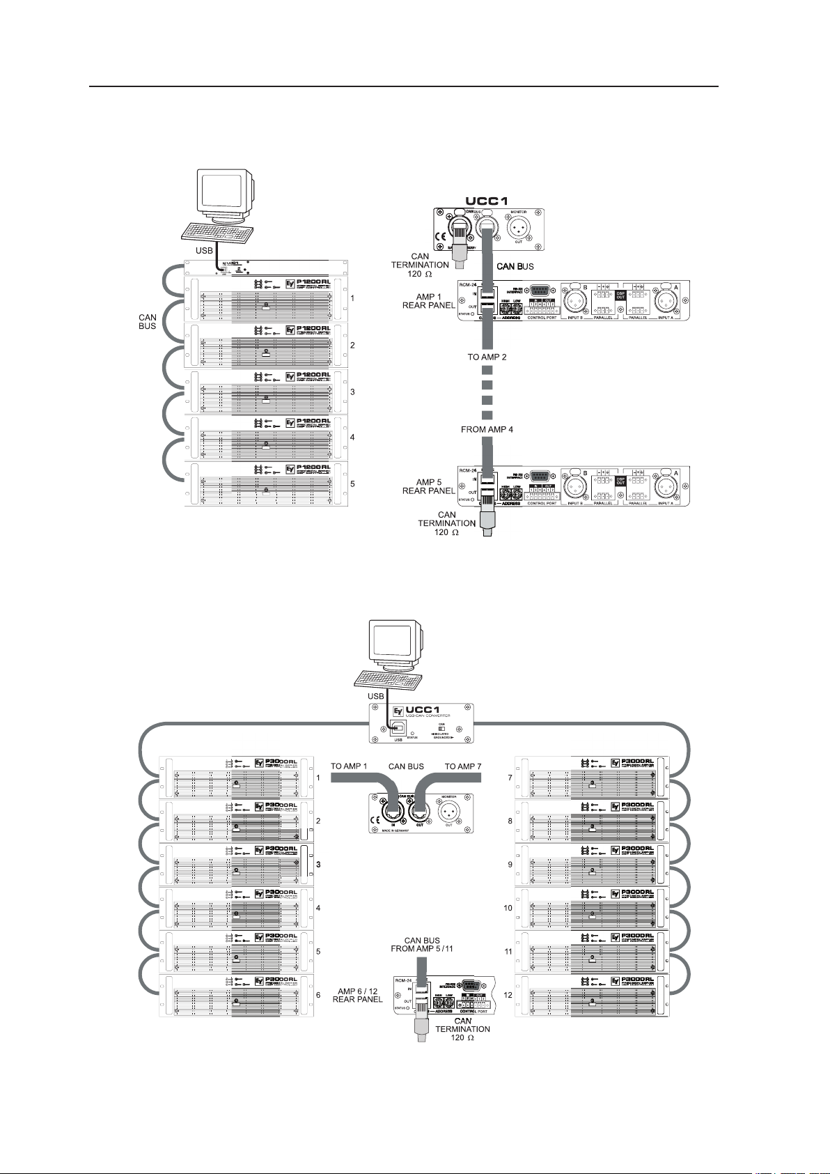
The following diagrams show examples of the data-bus wiring for different order of size:
System with 5 amps and one UCC1 / PC at the beginning of the bus
Terminators at the UCC1 ( rst unit on the bus) and at amp 5 (last unit on the bus)
System with 2 amp-racks and an UCC1 / PC in the middle
Terminators at amp 6 ( rst unit on the bus) and amp 12 (last unit on the bus)
Page 13

System with several amp-racks and several UCC1 / PCs
Terminators at amp 10 ( rst unit on the bus) and amp 16 (last unit on the bus)
the power amp inputs and outputs. This monitor-bus allows software-controlled monitoring of the input and
output signals of all power amps that are included in the remote network, without the need for additional wiring.
The monitor signal is present at the UCC1’s XLR-type MONITOR Output connector for further distribution
to (e.g.) a mixing console to be monitored via headphones or an active monitor speaker connected
Page 14

The CAN-bus allows using different data rates, with the data
works allow baud rates up to 500kbit/s.
exceeds 1,000m
500 kbit/s
250 kbit/s
250 m
500 m
62.5 kbit/s
20 kbit/s
2500 m
5000 m
According to the ISO 11898-2 standard, CAN-bus data transfer cabling has to be carried out using
Twisted-Pair cables with or without shielding providing a characteristic impedance of 120
Ω
a CAN-bus need to be terminated with 120
termination-plugs.
The maximum bus-length depends on the actual data transfer rate, the kind of data transfer cable being
coherencies for CAN-networks consisting of up 64 participants
Cable for data Transmission
Termination
Cable Diameter
0 ... 40 m
Ω
/m
0.25 ... 0.34 mm²
AWG23, AWG22
Ω
40 ... 300 m
/m
0.34 ... 0.6 mm²
AWG22, AWG20
500 kbit/s bei 100 m
300 ... 600 m
Ω
/m
0.5 ... 0.6 mm²
AWG20
... 300
600 ... 1000 m
Ω
/m
0.75 ... 0.8 mm²
AWG18
Ω
... 300
Ω
62.5 kbit/s bei 1000 m
With longer cables and many participants on the CAN-bus, termination resistors with higher impedance than the
speci ed 120
are recommended to reduce the ohmic load of the interface drivers and therefore the voltage drop
The following table is meant for rst assessment of necessary cable diameters for different bus lengths
and bus-participant numbers
32
64
0.25 mm² bzw. AWG24
0.34 mm² bzw. AWG22
0.34 mm² bzw. AWG22
250 m
0.34 mm² bzw. AWG22
0.5 mm² bzw. AWG20
0.5 mm² bzw. AWG20
500 m
0.75 mm² bzw. AWG18
0.75 mm² bzw. AWG18
Additionally, the length of branch lines – for participants that are not directly connected to the CAN-bus
– is also of importance. For data transfer rates of up to 125kbit/s, the maximum length of a single stub
cable should not exceed 2m. For higher bit rates a maximum length of only 0.3m is still permissible. The
entire length of all branch lines should not exceed 30 m.
General Note:
As long as only short distances (up to 10m) are concerned, common RJ-45 patch cables with
Ω
characteristic impedance (AWG 24 / AWG 26) can be used for the cabling inside of a rack-
shelf system. The previously outlined guidelines for network cabling are mandatory as far as the
.
Page 15

The following tables allow determining power supply and cabling requirements. The values of the
column „1/8 max. Output“ are relevant for „normal“ operation. These values are based on operating the
The power drawn from the mains network is converted into acoustic output power to feed the connected
auxiliary means for calculating the temperatures inside of a rack-shelf system/cabinet and the ventilation
efforts necessary. The column “Pd” lists the leakage power in relation to different operational states. The
column “BTU/hr” lists the dispensed heat amount per hour
[V]
[A]
[W]
out
[W]d [W]
(3)
230V
0.558585
290
(1)
Ω
Ω
230V
6.40
2 x 380
425
(1)
230V
2030
2 x 600
830
2832
(1)
230V
6.60
2 x 200
830
2832
(2)
Ω
Ω
230V
3.80
675
2 x 75
525
(1)
Ω
Ω
230V
3.78
670
2 x 50
570
(1)
Ω
Ω
230V
9.69
2 x 500
870
2969
Alarm Operation (-3dB)
(1)
230V
7.27
2 x 250
870
2969
[V]
[A]
[W]
out
[W]d [W]
(3)
230V
0.457070
239
(1)
Ω
Ω
230V
4.97
920
2 x 280
360
(1)
Ω
Ω
230V
8.16
2 x 450
680
2320
(1)
Ω
Ω
230V
5.13
960
2 x 150
660
2252
(2)
230V
2.90
520
2 x 56.3
407.5
(1)
230V
2.84
505
2 x 35
435
(1)
Ω
Ω
230V
7.32
2 x 350
710
2423
Alarm Operation (-3dB)
(1)
Ω
Ω
230V
5.48
2 x 175
680
2320
Page 16

Page 17

Page 18

WICHTIGE SICHERHEITSHINWEISE
WICHTIGE SERVICEHINWEISE
20
AUSPACKEN & GARANTIE
INSTALLATIONSHINWEISE
23
23
23
23
CONTROL PORT
23
ADDRESS
25
25
26
GROUND-LIFT SCHALTER
26
26
VERKABELUNG
27
28
CAN-BUS
30
30
31
SPECIFICATIONS / TECHNISCHE DATEN
32
34
35
ABMESSUNGEN
36
Page 19

WICHTIGE SICHERHEITSHINWEISE
ecks soll den Anwender auf nicht isolierte Leitungen
führen können.
sowie Servicehinweise in der zum Gerät gehör-
enden Literatur aufmerksam machen.
2.
3.
5.
Spritzwasser ins Geräteinnere eindringen kann. Platzieren Sie keine mit Flüssigkeiten gefüllte Objekte, wie Vasen
oder Trinkgefässe, auf dem Gerät ab.
6.
Verwenden Sie zum Reinigen des Gerätes ausschliesslich ein trockenes Tuch.
7.
Verdecken Sie keine Lüftungsschlitze. Beachten Sie bei der Installation des Gerätes stets die entsprechenden
8.
Vermeiden Sie die Installation des Gerätes in der Nähe von Heizkörpern, Wärmespeichern, Öfen oder anderer
Wärmequellen.
9.
Verwenden Sie mit dem Gerät ausschliesslich Zubehör/ Erweiterungen, die vom Hersteller hierzu vorgesehen sind.
WICHTIGE SERVICEHINWEISE
ACHTUNG:
die nicht in der Bedienungsanleitung beschrieben sind, ausser Sie sind hierfür quali ziert. Überlassen
Sie sämtliche Servicearbeiten und Reparaturen einem ausgebildeten Kundendiensttechniker.
Trenntransformator zu verwenden.
3.
Vor einem Umbau mit Nachrüstsätzen, Umschaltung der Netzspannung oder sonstigen Modi kationen ist das Gerät
stromlos zu schalten.
verbunden sind (sekundär), betragen 6mm und sind unbedingt einzuhalten.
5.
Spezielle Bauteile, die im Stromlaufplan mit dem Sicherheitssymbol gekennzeichnet sind, (Note) dürfen nur durch
Originalteile ersetzt werden.
6.
auch die Beschaffenheit des Arbeitsplatzes.
8.
SAFETY COMPONENT ( MUST BE REPLACED BY ORIGINAL PART )
Page 20

20
Sie haben sich mit einer Endstufe der PRECISION SERIES von Electro-Voice
für ein Gerät modernster Technologie entschieden.
triebssicherheit. Jede Endstufe ist mit dem RCM-24 Remote Control Modul ausgestattet, welches
die zentrale Kon guration, Steuerung und Überwachung aller relevanten Endstufenparameter (wie
Ausgangsstrom, -spannung, Lastimpedanz, ...) ermöglicht.
senen Lautsprecher. Zu diesen Schutzschaltungen gehören dynamische Audio-Limiter, DC/HF-Protec-
tions, Back-EMF-Protection, Inrush Current Limiter, Short Circuit Protection
turüberwachung der Endtransistoren und der Netztransformatoren.
gewährleistet. Die Luftführung ist Front-to-Rear, was den problemlosen Betrieb in grossen und
schmalen Endstufen-Racks ermöglicht.
einen vollständigen Überblick über den
gesamten Systemzustand und die
temparameter. Das RCM-24 Modul
erlaubt die Anbindung an ein Remote Control Netzwerk mit bis zu 250 Endstufen. Ein komplettes
z. B. Einschaltstatus, Temperatur, Aussteuerung, Limiting, Ansprechen von Schutzschaltungen, Ab-
weichungen der Lastimpedanz usw., werden zentral erfasst und dargestellt. Dadurch
eingegriffen werden. Eine automatische Reaktion auf Über- oder Unterschreitung bestimmter
der beiden Endstufenkanäle überwacht. Jede Über- oder Unterschreitung der eingestellten
werden so während des normalen Anlagenbetriebs erkannt und dargestellt. Eine wesentlich
genauere Überprüfung der angeschlossenen Lautsprecher ermöglicht die integrier-
te Impedanz-Messfunktion. Dabei wird mit Hilfe des internen Signal-Generators und der
gen über den gesamten Frequenzbereich gemessen und als Impedanzkurve am PC Bild-
schirm dargestellt. Der gemessene Impedanzverlauf kann jederzeit mit einem Referenz-
wert verglichen werden, wodurch schon geringste Lautsprecherdefekte oder Mängel erkennbar sind.
Page 21

21
che Signalverarbeitungsfunktionen zur Verfügung. Enthalten sind insgesamt 20 parametrische
sich die Steuereingänge der Endstufen zur netzwerkunabhängigen Umschaltung auf ein ande-
ein absoluter Spitzenwert für digitale Audiogeräte.
AUSPACKEN & GARANTIE
Öffnen Sie die Verpackung und entnehmen Sie die Endstufe. Zusätzlich zu dieser Bedienungsanleitung
ausgefüllt ist, denn nur so können Sie etwaige Garantieansprüche geltend machen. Sie haben
auf das Gerät 36 Monate Garantie, die ab dem Zeitpunkt der Aushändigung durch den Händler gilt.
die Entlüftung an der Geräterückseite nicht behindert wird. Für den Einbau in Gehäuse und Gestell-
schränke ist zu beachten, daß eine ausreichende Belüftung der Geräte möglich ist. Zwischen der End-
stufen Rückseite und der Schrank/Rack-Innenseite ist ein freier Luftkanal bis zur oberen Rack- oder
temperatur der übrigen im Gestellschrank be ndlichen Geräte beachtet werden.
jedem Fall Einbauschienen oder die als Zubehör
erhältlichen Rackeinbauwinkel NRS 90235
der Frontblende zu verhindern.
Achtung:
starken Staubablagerungen und starken Vibrationen
Wenn die Endstufe direkt von einem kalten an einen warmen Ort gebracht wird, kann sich Feuchtigkeit
auf Innenteilen niederschlagen. Das Gerät darf erst in Betrieb genommen werden, wenn es sich
auf die geänderte Temperatur erwärmt hat (nach etwa einer Stunde). Sollte ein fester Gegenstand
oder Flüssigkeit in das Gehäuse gelangen, trennen Sie sofort die Stromquellen vom Gerät ab und
Zur Reinigung des Gerätes dürfen keine Sprühmittel verwendet werden, da diese dem Gerät schaden
44.45
1/2
Page 22

22
zeige nicht leuchtet, ist das Gerät nicht mit dem Stromnetz verbunden, die
welcher über das RCM-24 oder über Easy Remote aktiviert werden kann.
Wenn die PROTECT-Anzeige au euchtet, hat eine der internen Schutzschaltungen
wie Übertemperatur, Kurzschluss, Back-EMF, Hochfrequenz am Ausgang.... ange-
sprochen. Die Endstufen werden in diesem Fall über die Ausgangsrelais von der Last
getrennt, um etwaige Schäden an den Lautsprechern oder der Endstufe
selbst zu verhindern. Die Fehlerursache, beispielsweise eine kurzgeschlossene
wartet werden, bis die Endstufe sich selbständig wieder in den normalen Betriebs-
zustand schaltet.
verlischt diese Anzeige.
trieben wird. Eine höhere Eingangsspannung hat keine Erhöhung der Spitzenausgangs-
spannung zur Folge.
tisch, da der interne Limiter Eingangspegel bis zu +21dBu auf einen Klirrfaktor von
ca. 1% ausregeln kann. Leuchtet diese LED jedoch dauerhaft sollte die Lautstärke
in der Mitte der Frontblende wird das Gerät eingeschaltet. Eine
dass der Leitungsschutzschalter des Stromnetzes beim Einschalten der Endstufe anspricht. Die
wodurch etwaige Einschaltgeräusche effektiv unterdrückt werden. Während dieser Verzögerung
Wurde das Gerät z.B. im Standby Modus per POWER Schalter ausgeschaltet, so wird es sich nach
dem Einschalten wieder in diesem Modus be nden.
Page 23

23
steckverbindungen, die im Lieferumfang enthalten sind, erfolgen. Die XLR-Eingangsbuchsen
sind nach IEC Norm 268 beschaltet. Für den Fall, dass die Eingänge potenzialfrei sein müssen,
geschalteten Schraubsteckverbindungen erfolgen. Die Buchsen PARALLEL ermöglichen aber
auch ein einfaches „Durchschleifen“ des Signals zu weiteren Endstufen ohne aufwändige Splitkabel.
An der Buchse DSP OUT liegt das DSP-Ausgangssignal, also das Signal hinter dem digitalen Signal-
gelangt entsprechend verstärkt an die Endstufenausgänge.
z.B. zur Leistungserweiterung. Das Ausgangssignal ist elektronisch symmetrisch, der Nennpegel
Ω
Widerstände auf +5V (offen). Zum Aktivieren können die Steuereingänge über externe
Zustand (Off) hochohmig sind. Im aktiven Zustand (On) sind die Ausgänge gegen Masse geschlossen.
oder Relais ansteuern. Der +5V Referenzanschluss dient zur Versorgung der extern angeschlossenen
gemeldet werden. Nähere Hinweise zur Kon guration des Control Ports nden Sie in
der IRIS Dokumentation.
zur Presetumschaltung oder zur Parameterkontrolle.
symmetrisch mit einer Eingangsemp ndlichkeit von
+6dBu (1.55V) für den direkten Betrieb mit Misch-
Page 24

24
se können die Remote Verstärker problemlos in Medien- und Touchpanel-Steuerungen integriert
werden. Programmierhinweise und eine vollständige Protokollbeschreibung nden Sie in der
ADDRESS
des Verstärkers ein. In einem CAN-Netzwerk können Sie die Adressen
01 bis 250 (FA hex) verwenden. Achtung: Jede Adresse darf im System nur
einmal vorkommen, da es sonst zu Netzwerk-Kon ikten kommt. Die
Adresseinstellung erfolgt in Hexadezimal. Der Wahlschalter LOW ist
das niederwertige Digit, der Schalter HIGH ist das höherwertige Digit.
Adress-Tabelle:
Adresse
Adresse
008
0 ... F
090 ... F
0 ... F
A
0 ... F
2
0 ... F
32 ... 47
0 ... F
3
0 ... F
48 ... 63
C
0 ... F
4
0 ... F
64 ... 79
0 ... F
208 ... 223
5
0 ... F
80 ... 95
0 ... F
224 ... 239
6
0 ... F
96 ... 111
0 ... A
240 ... 250
7
0 ... F
CAN-Bus angesteckt ist. Wenn der Verstärker mit Adresse 0 eingeschaltet wird, werden
sämtliche internen Parameter auf 0 bzw. Bypass und das Routing auf 2-in-2 gestellt. Der Ver-
stärker verhält sich dann völlig linear, die Signalverarbeitungsfunktionen sind deaktiviert.
Jeder Verstärker hat zwei RJ-45 Buchsen für den Remote CAN-Bus.
Weiterschleifen des Remote-Netzwerkes. Zur Verkabelung im Rack können
Abschlusswiderstand (im Lieferumfang).
Ausführliche Richtlinien zur Verdrahtung und Buslänge nden Sie im
An den beiden RJ-45 Buchsen liegt auch das symmetrische Audio-
Page 25

EASY REMOTE
Über Easy-Remote kann die Endstufe auf einfache Weise ferngesteuert,
ein- und ausgeschaltet werden. Die Easy Remote Funktion kommt
nur bei Geräten ohne RCM-24 Modul zum Tragen. Eine Steuerung
von Geräten mit RCM-24 Modul per Easy Remote ist nicht sinnvoll.
EASY REMOTE IN
Werden die Pins der EASY REMOTE IN Buchse offen gelassen bzw. mit +5V beaufschlagt, so schaltet
das Gerät ein. Bei einer Verbindung der Pins oder 0V vom Steuerausgang, schaltet das Gerät in
den Standby Modus.
EASY REMOTE SLAVE
An EASY REMOTE SLAVE können weitere Geräte mit Easy Remote Funktion angeschlossen werden
(z.B. zur Rack-ON/OFF Steuerung bei mehreren Geräten in einem Rack).
Das Einschalten der Slave-Geräte erfolgt zeitverzögert um ein Ansprechen von Netzsicherungen
zu vermeiden.
ENDSTUFENAUSGÄNGE
RÜCKSEITE
Die LED STATUS dient zur Kontrolle der Kommunikation am CAN-Bus.
Wenn die Adresse 00 eingestellt und die Endstufe softwaremässig vom
CAN-Bus abgekoppelt ist, blinkt die LED regelmässig alle 3 Sek. kurz
auf.
Sobald eine Kommunikation am CAN-Bus erkannt wurde, wird die LED immer dann für mindestens
100 ms aktiviert, wenn die Endstufe selbst Daten auf den CAN-Bus sendet.
Die STATUS LED kann auch vom PC aktiviert werden. Die LED der betreffenden Endstufe blinkt dann
in einem schnellen regelmässigen Rhythmus, alle anderen Status-LEDs im System bleiben dunkel.
Diese Funktion dient zur Überprüfung der Kommunikation und zur schnellen Identikation einer
Endstufe in einem grösseren System (s. a. IRIS Dokumentation).
Für die Endstufenkanäle A und B sind 4-polige Schraubklemmen vorgesehen.
Über zwei eingebaute Audio-Ausgangsübertrager wird die Nennausgangs-
spannung der Endstufe auf 100V bzw. 70V für Lautsprechernetze
transformiert. Je nach Konguration steht die entsprechende Ausgangs-
spannung potentialfrei an den Ausgangsklemmen zur Verfügung.
Die Anzahl der maximal anschliessbaren Lautsprecher ist erreicht, wenn die
Gesamtleistungsaufnahme des Lautsprechernetztes dem Nennleistungswert der Endstufe entspricht.
Der Nennlastwiderstand der Endstufe sollte dabei nicht unterschritten werden.
Die Nennleistungswerte und Nennlastwiderstände entnehmen Sie bitte dem Kapitel „Technische Daten“.
Vorsicht: Die Ausgänge können im Betrieb berührungsgefährliche Spannungen annehmen. Die
angeschlossenen Lautsprecherkreise sind aus diesem Grund gemäss den geltenden
Sicherheitsbestimmungen zu installieren. Die Installation darf nur durch entsprechend
geschulte Fachkräfte durchgeführt werden.
Für das Errichten und Betreiben von 100V-Lautsprecheranlagen ist die VDE-Bestimmung
DIN VDE 0800 zu beachten.
Besonders bei 100V-Lautsprecheranlagen für Alarmierungszwecke sind alle Schutz massnahmen für die Bemessungsklasse 3 auszulegen. Vor der Inbetriebnahme der
Endstufe muss in jedem Fall die an der Klemmleiste montierte Abdeckung
geschlossen werden.
25
Page 26

26
Auslieferungszustand
220V, 230V, 240V
70V Ausgangsspannung
Achtung:
durch Ziehen des Netzsteckers sichergestellt werden.
Alle Schrauben zur Haubenbefestigung entfernen
- Gerät durch Abnehmen der Haube öffnen
Auf Printplatte 86276:
für 100V Ausgangsspannung: Brücke R56 schliessen
für 70V Ausgangsspannung: Brücke R56 öffnen
die Endstufe zusammen mit anderen Geräten in einem 19“-Rack betrieben
wird, sollte der Schalter in Stellung GROUNDED stehen. Wird die Endstufe
aus. Die Sicherung darf nur gegen eine gleichwertige Sicherung mit
gleicher Strom-, Spannungs- und Auslösecharakteristik getauscht werden.
durchbrennen, kontaktieren Sie bitte die
Alle an das Gerät angeschlossenen Kabel, insbesondere das
Alle Schrauben zur Befestigung der Ausgangsbuchsenblende
entfernen.
Zur Auswahl der Ausgangsspannung dienen die Steckkontakte
sprechenden Stecker (grau hinterlegt) ab und stecken ihn auf
den Steckkontakt für die gewünschte Spannung
Page 27

27
Als NF-Verbindung wählen Sie am besten symmetrisch ausgelegte Kabel (2 Signaladern + Schirm-
ge echt) mit XLR-Stecker. Obwohl alle Endstufeneingänge auch unsymmetrisch beleget werden
symmetrischen Verbindung dar. Die meisten Audiogeräte verfügen über symmetrisch aufgebaute Aus-
gänge. Der Schirm im Kabel verbindet bei symmetrischer Signalführung alle metallischen Gehäuse
XLR-Steckerbelegung
XLR (male)
XLR (female)
tive-, Industrie- und Sicherheits-Bereich durchgesetzt und über Jahre hinweg bewährt hat. Der
CAN-Bus ist eine symmetrische serielle Schnittstelle zur Übertragung von Kommandos und Da-
ten. Die Steuerung der Endstufen erfolgt von einem PC mit IRIS Intelligent Remote & Integra-
ted Supervision Software. Als Interface zwischen PC und CAN-Bus dient der UCC1 USB-CAN
Converter. Pro CAN-Bus lassen sich 100 Endstufen bis zu einer maximalen Kabellänge von
terer CAN-Bus notwendig. Insgesamt kann die IRIS Software bis zu 250 Endstufen verwalten.
alle Teilnehmer sind an einer einzigen Zweidrahtleitung (Twisted-Pair-Kabel, geschirmt oder ungeschirmt)
angeschlossen, wobei die Verkabelung von einem Busteilnehmer zum nächsten verlaufen muss. Jedes
auch eine gemeinsame Masseleitung (CAN_GND) in der Netzwerkverkabelung mitgeführt. Damit
Jeder Bus-Teilnehmer hat 2 RJ-45 Buchsen für den Remote CAN-Bus. Die Buchsen sind parallel
geschaltet und dienen als Eingang und Ausgang (zum Weiterschleifen) des Remote-Netzwerkes.
Ω
Abschlusswiderstand terminiert werden. Zu
diesem Zweck liegen dem UCC1 zwei Abschluss-Stecker CAN-TERM 120
bei. Stecken Sie diese
Abschluss-Stecker in die freien RJ-45 Buchsen des ersten und des letzten Gerätes am CAN-Bus.
oder ein UCC1 USB-CAN Converter ist. Somit
Auch mehrere UCC1 und PCs am CAN-Bus
sind möglich. Ingesamt können bis zu 100
werden. Da die CAN-Schnittstel-
Page 28

28
ordnungen:
System mit 5 Verstärkern und einem UCC1 / PC am Bus-Anfang
Abschluss-Stecker am UCC1 (Bus-Anfang) und am Verstärker 5 (Bus-Ende)
System mit 2 Racks und einem UCC1 / PC in der Mitte
Abschluss-Stecker an Verstärker 6 (Bus-Anfang) und Verstärker 12 (Bus-Ende)
Page 29

29
System mit mehreren Racks und mehreren UCC1 / PCs
Abschluss-Stecker an Verstärker 10 (Bus-Anfang) und Verstärker 16 (Bus-Ende)
zum Abhören der Endstufeneingänge und –ausgänge mitgeführt. Dieser Monitorbus ermöglicht das
softwaregesteuerte Abhören der Eingangs- oder Ausgangssignale aller im Remote-Netzwerk
vorhandenen Endstufen ohne zusätzlichen Verdrahtungsaufwand. Am UCC1 liegt das Monitor
eingang gelegt und über Kopfhörer oder direkt über eine aktive Monitorbox abgehört werden.
Page 30

30
zur Buslänge ist. Wenn das Netzwerk nur eine geringe
Ausdehnung hat, sind höhere Baudraten bis zu 500 kbit/s
500 kbit/s
250 kbit/s
250 m
500 m
62.5 kbit/s
20 kbit/s
2500 m
5000 m
zugsweise Twisted-Pair-Leitungen, geschirmt oder ungeschirmt, mit einem Wellenwiderstand von
zum Einsatz kommen. Als Leitungsabschluss muss an beiden Enden ein Abschlusswiderstand
von 120
Ω
vorgesehen werden.
tenübertragungskabels sowie von der Anzahl der Bus-Teilnehmer. Die folgende Tabelle zeigt
die wesentlichen Zusammenhänge für CAN-Netzwerke mit bis zu 64 Teilnehmern:
Abschlusswider-
stand
Widerstandsbelag
0 ... 40 m
Ω
/m
0.25 ... 0.34 mm²
AWG23, AWG22
Ω
40 ... 300 m
/m
0.34 ... 0.6 mm²
AWG22, AWG20
500 kbit/s bei 100 m
300 ... 600 m
Ω
/m
0.5 ... 0.6 mm²
AWG20
... 300
600 ... 1000 m
Ω
/m
0.75 ... 0.8 mm²
AWG18
Ω
... 300
Ω
62.5 kbit/s bei 1000 m
spezi zierten 120
empfohlen, um die ohmsche Last für die Schnittstellentreiber und damit den Spannungs-
abfall von einem zum anderen Leitungsende zu verringern.
schiedliche Buslängen und verschiedene Anzahl der Bus-Teilnehmer:
Anzahl der Geräte am CAN-Bus
32
64
0.25 mm² bzw. AWG24
0.34 mm² bzw. AWG22
0.34 mm² bzw. AWG22
250 m
0.34 mm² bzw. AWG22
0.5 mm² bzw. AWG20
0.5 mm² bzw. AWG20
500 m
0.75 mm² bzw. AWG18
0.75 mm² bzw. AWG18
Zu beachten ist noch die Länge der Abzweigleitungen, wenn ein Teilnehmer nicht direkt am CAN-Bus
angeschlossen ist. Diese Stichleitungen sollten bei Datenübertragungsraten bis zu 125 kbit/s
eine Einzellänge von max. 2 m und bei höheren Bitraten von max. 0,3 m nicht überschreiten.
Grundsätzlich gilt:
Wellenwiderstand
verwendet werden (AWG 24 / AWG 26), wenn es sich nur um kurze Strecken handelt (bis zu 10 m).
oben genannten Richtlinien für die Netzwerkverkabelung einzuhalten.
Page 31

31
verwendet werden. Die Endstufe wurde hier mit VDE-Rauschen bei
der maximalen Ausgangs-
der Aussteuerungsgrenze betrieben wird.
WÄRMEENTWICKLUNG IN DER ENDSTUFE
d
). Die durch Verluste entstehende Wärmemenge verbleibt u.U. im Rack und
d
zeigt die Verlustleistung bei verschiedenen Betriebszuständen. Die Spalte BTU/hr
zeigt die abgegebene Wärmemenge je Stunde.
[V]
[A]
[W]
out
[W]d [W]
(3)
230V
0.558585
290
(1)
Ω
Ω
230V
6.40
2 x 380
425
(1)
230V
2030
2 x 600
830
2832
(1)
230V
6.60
2 x 200
830
2832
(2)
Ω
Ω
230V
3.80
675
2 x 75
525
(1)
Ω
Ω
230V
3.78
670
2 x 50
570
(1)
Ω
Ω
230V
9.69
2 x 500
870
2969
Alarmbetrieb (-3dB)
(1)
230V
7.27
2 x 250
870
2969
[V]
[A]
[W]
out
[W]d [W]
(3)
230V
0.457070
239
(1)
Ω
Ω
230V
4.97
920
2 x 280
360
(1)
Ω
Ω
230V
8.16
2 x 450
680
2320
(1)
Ω
Ω
230V
5.13
960
2 x 150
660
2252
(2)
230V
2.90
520
2 x 56.3
407.5
(1)
230V
2.84
505
2 x 35
435
(1)
Ω
Ω
230V
7.32
2 x 350
710
2423
Alarmbetrieb (-3dB)
(1)
Ω
Ω
230V
5.48
2 x 175
680
2320
(1)
Aussteuerung mit Sinus-Signal
(2)
Aussteuerung mit VDE-Rauschen
(3)
Page 32

32
70V
70V
28.5209.8
THD = 1%, 1kHz
410W
400W
590W
580W
THD = 1%, 1kHz, RMS, rated load
74.8V
75.4V
THD < 0.2%, 20Hz ... 20kHz
350W
350W
500W
500W
THD < 0.2%, 20Hz ... 20kHz
70V
70V
THD = 1%, 1kHz, no load
87V
88V
THD at rated output power,
< 0.05%
60Hz, 7kHz
< 0.1%
3.15kHz, 15kHz
< 0.2%
Crosstalk Attenuation
> 80dB
-3dB, ref. 1kHz
45Hz ... 22.5kHz
at 100Hz / 1kHz, 8
> 300 / > 200
Signal to Noise Ratio, Ampli er
A-weighted
Signal to Noise Ratio, System
A-weighted
at rated output power @ 4
+6dBu (1.55V)
+21dBu (8.7V)
20Hz ... 20kHz, balanced
20k
CMR
80dB
Output Voltage
Output Impedance
< 100
600
AD & DA Conversion
24 Bit, Sigma-Delta, 128 x Oversampling, Linear Phase
Sample Rate
48kHz
48 bit
Volume Control, Routing,
X-Over
Compressor / Limiter,
System (ampli er) at rated conditions, both channels driven, rated loads, unless otherwise speci ed.
Page 33

33
CAN-Bus, 10 ... 500 kbit/s, RJ-45 (PC Control)
Control Port / GPIO
6-pol. Phoenix
2 Control Inputs
Active / ON
0V (< 0.8V)
2 Control Outputs
Inactive / OFF High (Open Collector)
Active / ON
Low (< 0.5V / I = 0.7A)
Input Voltage
+32.0V max.
Switching Current 1.0A max.
240V, 230V, 120V, 100V / 50Hz ... 60Hz,factory con gured
max. output voltage at rated load
690W
870W
Audio limiters, High temperature, DC, HF, Back-EMF,
Cooling
483 x 132.5 x 426
Weight
22kg
24kg
Optional Input Transformer
Optional Output Transformer
Page 34

34
Page 35

35
ADA
D
DAD
A
ADA
D
24 BIT
DSP
SRAM
512k x
8
GAINRANGING
24 BIT ADC
GAINRANGING
24 BIT ADC
LP
F
LP
F
DUAL
24 BIT DAC
INPUT
PARALLEL
-15V
+15V
AMPLIFIER
INTERFACE
CONTROL / SUPERVISION:
INPUT / OUTPUT LEVEL METER
PILOT SIGNAL GENERATOR
PILOT SIGNAL DETECTION
IMPEDANCE MEASUREMEN
T
AMP INPUT CH. A (SIGNALA / SENSINA)
AMP INPUT CH. B (SIGNALB / SENSINB)
ANALOG
POWER
SUPPLY
CLOCK
12.288 MHz
POWER
SUPPLY
CPU +
FLASH
RAM
A
D
CAN
UART
RESET
WATCHDOG
EEPRO
M
AMP TEMPERATURE (TEMP)
OUTPUT CURRENT CH.A (OUTCURA+/-)
OUTPUT CURRENT CH.B (OUTCURB+/-)
AMP OUTPUT RELAYS (TIMER)
OUTPUT VOLTAGE CH.A (OUTVOLA+/-)
STANDBY POWER SOURCE
+5V
+3.3V
DC
DC
RJ-45
MONITOR BUS
CAN / RS-485
+5V
CAN / RS-485
TRANSCEIVER
MONITOR
OUT B
MONITOR
IN A
MONITOR
IN B
MONITOR
OUT A
SLAVE OUT A
SLAVE OUT B
CLOCK
SPI
D
A
D
A
DUAL ADC
DUAL AD
C
I/O
DEVICE
ADDRESS
STATUS
SIGNAL PROCESSING:
FILTERS, X-OVER
DELAY
COMPRESSOR, LIMITER
ROUTING, LEVEL, POLARITY
I/O
MAINS POWER ON/OFF (POWER_ON)
AMP TYPE CODE (AMP_ID1-8)
LIMITER CH. A (LIMOUTA)
LIMITER CH. B (LIMOUTB)
GPIO
CONTROL
PORT
8
OUTPUT VOLTAGE CH.B (OUTVOLB+/-)
INPUT LEVEL CH. B
INPUT LEVEL CH.
A
+5V
GND
GROUND
FAULT
DETECTION
AMP PROTECT (PROTECT)
CHASSIS
8
STANDBY/ON SIGNAL (STANDBY)
4
CHANNEL A
INPUT
CHANNEL B
PARALLEL
GROUND FAULT CH. A (GNDFLTA)
GROUND FAULT CH. B (GNDFLTB)
VU INPUT A
VU INPUT B
DSP DIGITALBOARD
80477
NRS 90227
NRS 90208
NRS 90208
Page 36

36
5,5
440,5
131
483
132,5
389,5
440
Page 37

373839
Page 38

Page 39

Page 40

40
Telex Communications Inc., 12000 Portland Ave. South, Burnsville, MN 55337, Phone: +1 952-884-4051, FAX: +1 952-884-0043
Germany
Subject to change without prior notice.
www.electro-voice.de
 Loading...