

Electro-Voice P3000, P3000 Series Service Manual

P3000
PRECISION SERIES
SERVICE MANUAL
The lightning flash with arrowhead symbol, within an equilateral triangle is intended to alert the user to the presence
of uninsulated “dangerous voltage” within the product’s
enclosure that may be of sufficient magnitude to constitute
a risk of electric shock to persons.
The exclamation point within an equilateral triangle is
intended to alert the user to the presence of important
operating and maintance (servicing) instructions in the
literature accompanying the appliance.
IMPORTANT SAFETY INSTRUCTIONS
1. Read these instructions.
2. Keep these instructions.
3. Heed all warnings.
4. Follow all instructions.
5. Do not use this apparatus near water.
6. Clean only with a damp cloth.
7. Do not block any of the ventilation openings.
Install in accordance with the manufactures instructions.
8. Do not install near any heat sources such as radiators, heat registers, stoves, or other apparatus that produce heat.
9. Only use attachments/accessories specified by the manufacturer.
10. Refer all servicing to qualified service personnel. Servicing is required when the apparatus has been
damaged in any way, such as power-supply cord or plug is damaged, liquid has been spilled or objects have fallen
into the apparatus, the apparatus has been exposed to rain or moisture, does not operate normally, or has
been dropped.
For US and CANADA only:
Do not defeat the safety purpose of the grounding-type plug. A grounding type plug has two blades and a third grounding prong.
The wide blade or the third prong are provided for your safety. When the provided plug does not fit into your outlet, consult an
electrican for replacement of the absolete outlet.
1. Security regulations as stated in the EN 60065 (VDE 0860 / IEC 65) and the CSA E65 - 94 have to be obeyed when
servicing the appliance.
2. Use of a mains separator transformer is mandatory during maintenance while the appliance is opened, needs to be
operated and is connected to the mains
3. Switch off the power before retrofitting any extensions, changing the mains voltage or the output voltage.
4. The minimum distance between parts carrying mains voltage and any accessible metal piece (metal enclosure),
respectively between the mains poles has to be 3 mm and needs to be minded at all times.
The minimum distance between parts carrying mains voltage and any switches or breakers that are not connected
to the mains (secondary parts) has to be 6 mm and needs to be minded at all times.
5. Replacing special components that are marked in the circuit diagram using the security symbol (Note) is only permissible
when using original parts.
6. Altering the circuitry without prior consent or advice is not legitimate.
7. Any work security regulations that are applicable at the location where the appliance is being serviced have to be strictly
obeyed. This applies also to any regulations about the work place itself.
8. All instructions concerning the handling of MOS - circuits have to be observed.
Note:
SAFETY COMPONENT (HAS TO BE REPLACED WITH ORIGINAL PART ONLY)
IMPORTANT SERVICE INSTRUCTIONS
CAUTION: These servicing instructions are for use by qualified personnel only. To reduce the
risk of electric shock, do not perform any servicing other than that contained in the
Operating Instructions unless you are qualified to do so. Refer all servicing to
qualified service personnel.
1-2

TECHNICAL SPECIFICATIONS
at rated output power 8ohms, one channel
driven, unless otherwise specified
Output Power
(20Hz - 20kHz /THD≤ 0,1%)
into8 Ohms 2 x 750 W
into 4 Ohms 2 x 1200 W
into 8 Ohms bridged 1 x 2400 W
Output Power
(1kHz / THD = 1,0%)
into 8 Ohms 2 x 850 W
into 4 Ohms 2 x 1300 W
into 8 Ohms bridged 1 x 2800 W
Technical Specification
Frequency Response 10 Hz - 30 kHz /
1dB
Max. Output Level 91V / RMS
before Cliping, reference 1 KHz / THD =
1%
Voltage Gain 26 dB (constant gain option)
reference 1kHz
Input Sensitivity 0 dBu/0.775 V
at rated output power 6 dBu/1.55 V
reference 1 kHz
Maximum Input Level 21 dBu / 9 V
Input Impedance 20 kOhm
active balanced
THD < 0.05%
at rated output power
MBW = 80 kHz, f = 1kHz
IMD - SMPTE < 0.01%
60 Hz, 7 kHz, typical
IMD - SMPTE < 0.01%
60 Hz, 7 kHz, at rated output power
Signal / Noise Ratio > 105 dB
A-weighted, RMS to rated output level,
Input sensitivity + 6dBu
Crosstalk < -70 dB
at rated output power reference 1 kHz
Damping Factor > 300
internal, 1kHz
DIM 30 < 0.01%
DIM 100 < 0.01%
Slew Rate internal > 40 V / ms
Power Consumption 1650 VA
1/8 rated output power 4 Ohm
Dimensions (WxHxD) 483x132.5 x 426mm
19 x 5.2 x 16.77 (in)
Weight 29 kg (63.9 Ibs)
Optional Input Transformer 90176
DESCRIPTION
EV power amplifiers of the PRECISION
SERIES meet the stringent requirements of
tough touring applications. They are protected against over-temperature, overload,
shorted outputs, radio frequency interference
and DC faults. The power transistors are
protected from damage from reverse feeding
of electrical energy by means of an additional
special protective circuit. For the so-called
soft-start, the power outputs are switched on
delayed via relays. An inrush current limiter
circuit prevents the mains fuses from being
blown.
Maximum precision is also guaranteed as
regards mechanical construction and finish.
The robust steel chassis features remarkable torsion resistance and is specially designed to cope with the tough wear and tear
associated with going on tour. Thermal
stability is guaranteed by several low noise
3-stage fans which also means that they can
be used inside the studio.Comparator circuits constantly compare the power amplifiers’ input and output signal and control the
limiters under non-linear operating conditions. They protect the loudspeakers from
overload due to power stage clipping. The
PRECISION SERIES power amplifiers feature excellent transmission properties. The
power amplifier topology also makes for
extremely low distortion rates. Distortion factor (THD), intermodulation distortion
(SMPTE-IM) and transient intermodulation
distortion (DIM 30 and DIM 100) are so low
that they are only detectable with the most
sophisticated measuring equipment. Generously dimensioned power supplies with lowleakage toroidal-core transformers provide
considerable headroom well above the nominal ratings. V/I foldback limiter circuits
were deliberately not included in the PRECISION SERIES power amplifiers to facilitate operation at complex loads up to a phase
angle of +/- 90°.The inputs are electronically
balanced on XLR connectors. (Isolation
transformers can be retrofitted). Direct Outs
in the form of XLR connectors (male), to loop
the signal through, are also standard features.
Architects and engineers
specifications
P 3000
STEREO POWER AMPLIFIER
PRECISION SERIES

The modes DUAL/Stereo or PARALLEL/Mono can be selected via the Input
Routing Switch. Furthermore, the PRECISION SERIES power amplifiers can also be
operated in “Mono Bridged” mode. The front
panel accommodates the dB-calibrated input
Gain controls which are designed as especially precise and safe-to-operate detented
potentiometers. The LED display provides
information about the power amplifers’ operating status. For the two channels, they
demonstrate readiness to operate, whether
there is a signal at the input or output, when
the Limiters have been activated and whether
one of the protective features has been
triggered. The power outputs Channel A,
Channel B and Bridged Out are available on
Speakon connectors. The rear side of the unit
accommodates the ON/OFF switches for the
integrated Hi and Lo cut filters, a groundlift
switch which separates the housing from the
circuit ground thus helping to prevent hum
loops and the operating modes selector to
mono bridged operation. They also feature
extremely quiet fans with front-to-rear airflow,
facilitating operation in large and narrow
amplifier racks.
# SERVICE INFORMATION
WARNING: No user serviceable parts inside.
Extremely hazardous voltages and currents
may be encountered within the chassis. The
servicing information contained within this
document is only for use by Electro-Voice
Authorized warranty repair stations and qualified service personnel. To avoid electric
shock DO NOT perform any servicing other
than that contained in the Operating instructions unless you are qualified to do so.
Otherwise, refer all servicing to qualified
service personnel.
NOTICE: Modification to Electro-Voice products is not recommended. Such modifications shall be at the sole expense of the
person(s) or company responsible, and any
damage resulting therefrom shall not be covered under warranty or otherwise.
#.1 ELECTRO-VOICE UNIFORM LIMITED
WARRANTY STATEMENT
Electro-Voice products are guaranteed
against malfunction due to defects in materials or workmanship for a specified period, as
noted in the individual product-line statement(s) below, or in the individual product
data sheet or owner’s manual, beginning with
the date of original purchase. If such malfunction occurs during the specified period, the
product will be repaired or replaced (at our
option) without charge. The product will be
returned to the customer prepaid. Exclusions
and Limitations: The Limited Warranty does
not apply to: (a) exterior finish or appearance;
(b) certain specific items described in the
individual product-line statement(s) below, or
in the individual product data sheet or owner’s
manual; (c) malfunction resulting from use or
operation of the product other than as specified in the product data sheet or owner’s
manual; (d) malfunction resulting from misuse or abuse of the product; or (e) malfunction occurring at any time after repairs have
been made to the product by anyone other
than Electro-Voice or any of its authorized
service representatives. Obtaining Warranty
Service: To obtain warranty service, a customer must deliver the product, prepaid, to
Electro-Voice or any of its authorized service
representatives together with proof of
purchase of the product in the form of a bill
of sale or receipted invoice. A list of authorized service representatives is available from
MARK IV AUDIO Deutschland
Hirschberger Ring 45
D - 94315 Straubing
Postfach 0254 D- 94302 Straubing
Tel.: ++49 (0)9421/7060
Fax: ++94(0)9421/706265
MARK IV AUDIO (Europe) AG
Keltenstr. 5
CH-2563 Ipsach
Tel.: ++41 (0)32-516833
Fax: ++41 (0)32-511221.
Incidental and Consequential Damages
Excluded: product repair or replacement
and return to the customer are only remedies provided to the customer. Electro-Voice shall not be liable for any incidental or
consequential damages including, without
limitation, injury to persons or property or
loss of use. Some states do not allow the
exclusion or limitation of incidental or consequential damages so the above limitation or exclusion may not apply to you.
Other Rights: This warranty gives you specific legal rights, and you may also have
other rights which vary from state to state.
Electro-Voice Electronics are guaranteed
against malfunction due to defects in materials or workmanship for a period of three (3)
years from the date of original purchase.
Additional details are included in the Unifom
Limited Warranty statement.
#. 2 TECHNICAL ASSISTANCE
For applications assistance or other technical
information, contact the Applications Engineer. You can call or write:
MARK IV AUDIO Deutschland
Hirschberger Ring 45
D - 94315 Straubing
Postfach 0254 D- 94302 Straubing
Tel.: ++49 (0)9421-7060
Fax: ++49 (0)9421-706265
MARK IV AUDIO (Europe) AG
Keltenstr. 5
CH-2563 Ipsach
Switzerland
Tel.: ++41 (0)32-516833
Fax: ++41 (0)32-511221
Specifications subject to change without
notice
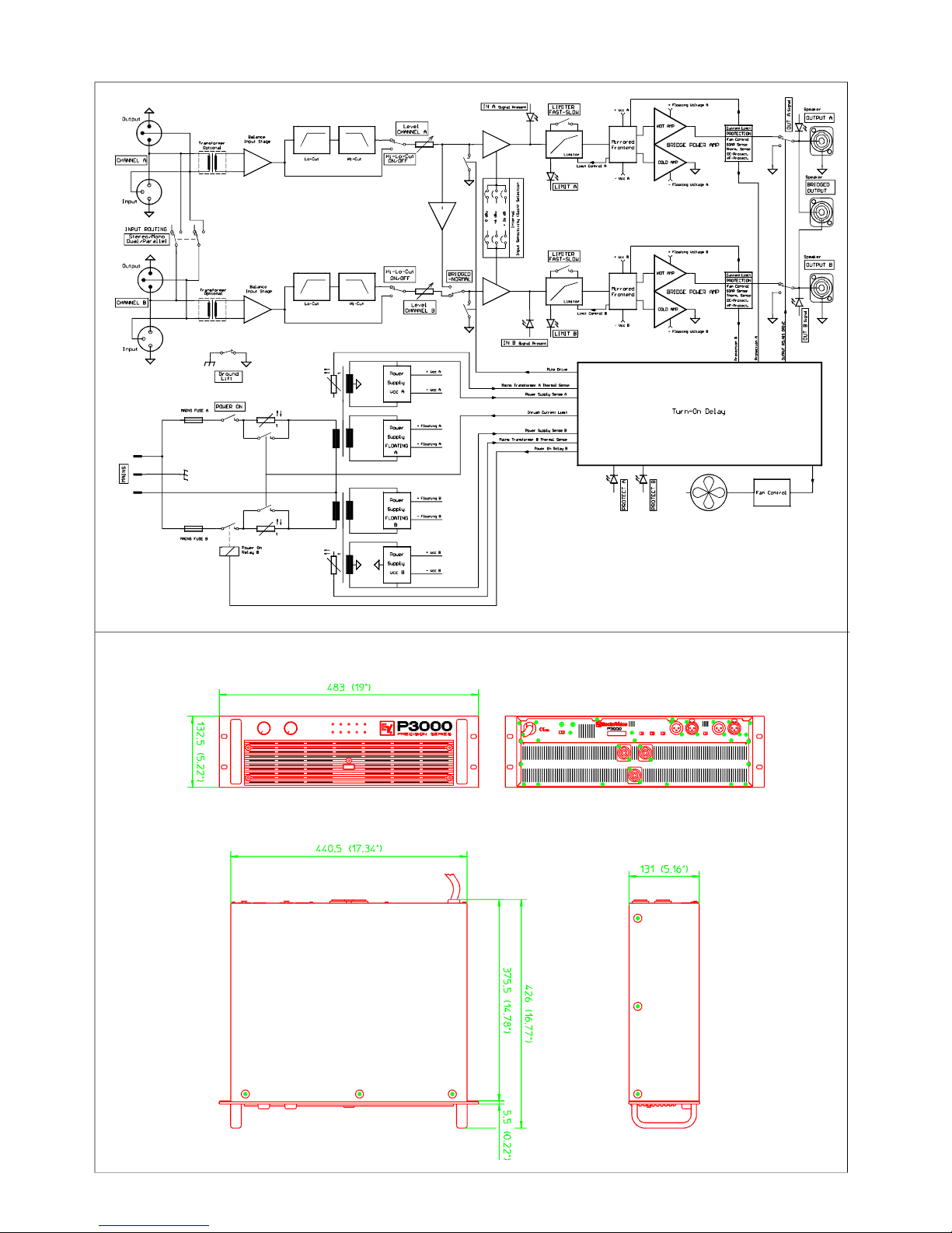
DIMENSIONS
BLOCK DIAGRAM

1
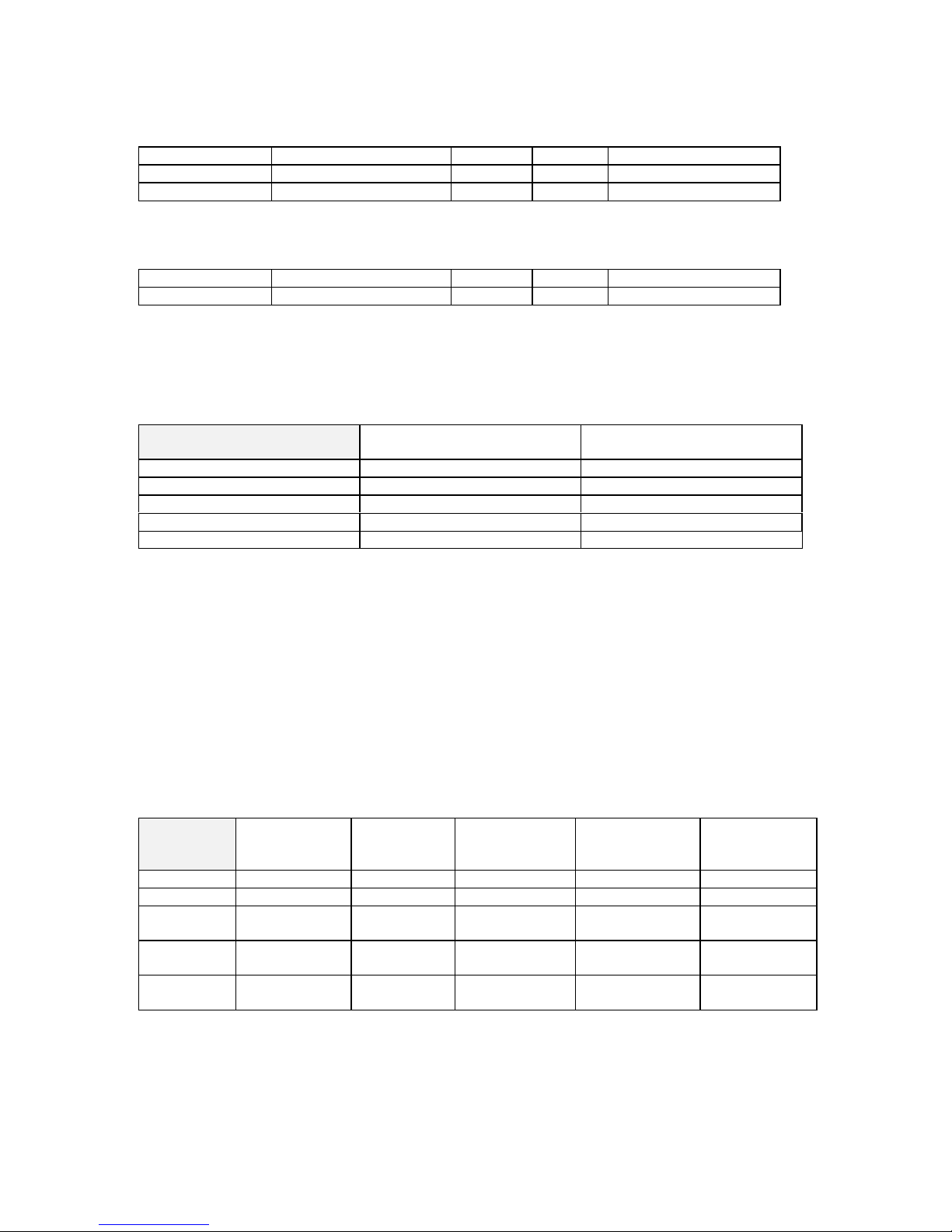
SPECIFICATIONS: P3000 entire unit
Measuring Standard IEC 268 part 3IHF-A
0 dBu = 775 mV (RMS)
A. POWER SUPPLY
1. voltage supply AC
2. nominal supply voltage, depending on the model: 120V/230V/240V
3. nominal mains frequency: 50 - 60 Hz
4. nominal power consumption (2x1200W/4Ω): 4100 W
5. nominal power consumption (2x120W/4Ω): 1500 W
6. power consumption at 1/8 of the nominal power (150W/4Ω): 1650 W
7. deviation range of the power supply: -10 % … +10 %
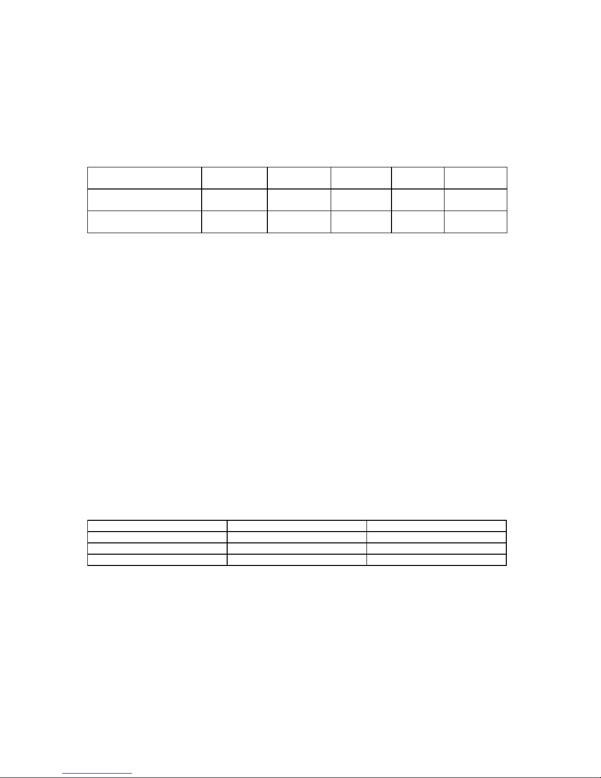
B. INPUT PROPERTIES
• level control fully open
Input Nominal input level
(nominal source EMK)
select jumper internally
Nominal
output power
Nominal load
impedance
0 dBu +6 dBu +26 dB
Channel A/B +1 dBu +7 dBu +14 dBu 750 W
8 Ω
Channel A/B 0 dBu +6 dBu +13 dBu 1200 W
4 Ω
Channel A/B -2 dBu +4 dBu +11 dBu 1500 W
2 Ω
Channel BRIDGED 0 dBu +6 dBu +13 dBu 2400 W
8 Ω
Channel BRIDGED -2 dBu +4 dBu +11 dBu 3000 W
4 Ω
Maximum input level: +21 dBu
C. OUTPUT PROPERTIES
• nominal output power with THD = 0.1 %, 20 Hz … 20 kHz, MBW = 80 kHz
• maximum output power at 1 kHz with THD = 1 %, MBW = 80 kHz
Output connector Nominal
load
impedance
Nominal output
power Dual
Mode
Maximum output
power Dual Mode,
THD=1 %
Single channel
output
power)
1
Nominal
output
voltage
SPEAKER A/B
8 Ω
750 W 850 W 950 W 77.5 V
SPEAKER A/B
4 Ω
1200 W 1300 W 1700 W 69.3 V
SPEAKER A/B
2 Ω
1500 W 1800 W 2000 W 54.8 V
SPEAKER BRIDGED
8 Ω
2400 W 2600 W 3400 W 138.6 V
)1 measured with Dynamic Headroom Test-Signal according to IHF-A: 1 kHz Burst, 20ms ON, 480 ms OFF
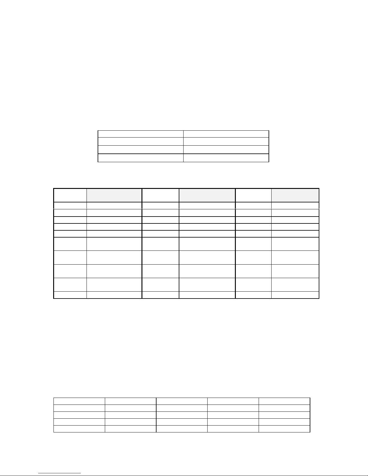
D. Idling output voltage
Output connector SPEAKER A/B SPEAKER BRIDGED
Max. idling voltage
91 V (RMS) 182 V (RMS)
E. Stabilizing
with nominal load impedance, Dual Mode, standard output voltage
8 Ω 4 Ω
Stabilizing
0.325 % 0.686 %
Stabilizing level
0.028 dB 0.059 dB
2
F. FREQUENCY RESPONSE
• -3 dB level drop, referenced to the level at the standard frequency of 1 kHz
• the power amplifier's border frequencies are at 13 Hz and 40 kHz respectively, referenced to -1 dB
Amplification frequency response
Input Output f (u) f (o) Remarks
INPUT A/B SPEAKER A/B <10 Hz 75 kHz HI-LO-CUT Off
INPUT A/B SPEAKER A/B 20 Hz 35 kHz HI-LO-CUT On
Distortion-limited transmission range (performance bandwidth)
• THD = 0.1 %, 1/2 nominal power at 4 ohms, MBW = 500 kHz
Input Output f (u) f (o) Remarks
INPUT A/B SPEAKER A/B <10 Hz 48 kHz HI-LO-CUT Off
G. PHASE RESPONSE ±30° (20 Hz - 20 kHz, HI/LO-CUT off)
H. INPUT IMPEDANCE 20 kΩ (20 Hz … 20 kHz)
I. AMPLITUDE NON-LINEARITY
Amplitude non-linearity Remarks
nominal overall distortion
<0.05 % MBW = 80 kHz, f = 1 kHz
standard overall distortion
<0.02 % MBW = 80 kHz, f = 1 kHz
IMD-SMPTE
<0.01 % 60 Hz, 7 kHz
DIM 30
<0.01 % 3.15 kHz, 15 kHz
DIM 100
<0.01 % 3.15 kHz, 15 kHz
J. CROSSTALK - at f = 1 kHz less than <-70 dB
K. DAMPING FACTOR - internal at f = 1 kHz >300
at f = 100 Hz >400
L. SLEW RATE - internal >40 V/µs
M. NOISE INTERFERENCE
- U(F) = external voltage un-weighted with B = 22 Hz … 22 kHz, effective value (IEC 268-1)
- U(G) = noise voltage, frequency-weighting filter according to CCIR-468-3, quasi peak weighted (IEC 268-1)
- U(A) = interference voltage A-weighted, dB(A), effective value (IEC 268-1)
- Signal-to-noise ratio referenced to a nominal output voltage of 69.3 V (1200W/4ohms)
- HI/LO-CUT ON, GND LIFT = GROUNDED
Interference
output voltage
S/N ratio Equivalent input
interference
voltage
Equivalent input
interference level
Residual
interference
output voltage
U(F)
< 615µV > 101 dB < 6.9µV < -101 dBu < 435µV
U(G)
< 3.65 mV > 85.5 dB < 41µV < -85.5 dBu < 1.55mV
U(A)
i.s.=0dBu
< 490µV > 103 dB < 5.5µV < -103 dBu < 345µV
U(A)
i.s.=6dBu
< 245µV > 109 dB < 5.5µV < -103 dBu < 170µV
U(A)
Gain=26dB
< 110µV > 116 dB < 5.5µV < -103 dBu < 90µV
The S/N ratio (A-weighted) at max. output voltage at 4Ω is >103 dB.
N. DIMENSIONS
Height : 132.5 mm (3 HU)
Width : 483 mm
Depth : 426 mm
O. WEIGHT m = 29 kg
3
P. EXTENSIONS optionally available 2 x input transformer NRS 90176
MEASURED SPECIFICATIONS: P3000 entire unit
Measurement conditions, unless differently specified:
• tolerance of measured values: ∆X = ±1.5 dB
• measuring frequency: f = 1 kHz
• stated levels refer to: U = 775 mV (0 dBu)
• level controls set to their clockwise limits
• pin assignment of the XLR-type connectors: PIN 1: GROUND
PIN 2: + INPUT
PIN 3: - INPUT
• source resistance for the induction via the XLR-type connector: R(Q) = 50 Ω
• MAIN-PCB numbers relate to the models as follows:
Type of unit MAIN - PCB
P3000 / 120 V 86211
P3000 / 230 V 86207
P3000 / 240 V 86207
• MAIN-PCB and POWER-AMP-PCB are provided with service connectors.
The Pin-assignment of these service connectors is as follows:
84157 86207
86211
86207
86211
CNSERV Assignment CNASERV Assignment CNBSERV Assignment
1 Kodierung 1
Limiter A&B OFF
1 n.c.
2 BIAS Hot - Side + 2 Service Limiter A 2 Service Limiter B
3 BIAS Hot - Side - 3 -15V 3 - 15 V
4 Hot - Out 4 GND 4 Fan voltage
5 BIAS Cold - Side + 5 + 15 V 5 Service Fan
Switch
6 BIAS Cold - Side - 6 heat sink temperature
A&B
6 Service Fan
Switch
7 GND 7 + U1 front-end A 7 + U1
front-end B
8 floating voltage + 8 - U1 front-end A 8 - U1
front-end B
9 floating voltage - 9 coding 9 coding
1. Operating voltage: U(B) = 120V/ 230V/ 240V
depending on the model: 50Hz ... 60Hz
2. Deviation limit of the operation voltage: ±10%
3. Power consumption (both channels driven):
3.1. at idling condition P(B) = 180 - 260 W
3.2. at standard operation (120W/4Ω) P(B) = 1500 W
3.3. at nominal condition (1200W/4Ω) P(B) = 4100 W
3.4. at 1/8 of the nominal power (150W/4Ω) P(B) = 1650 W
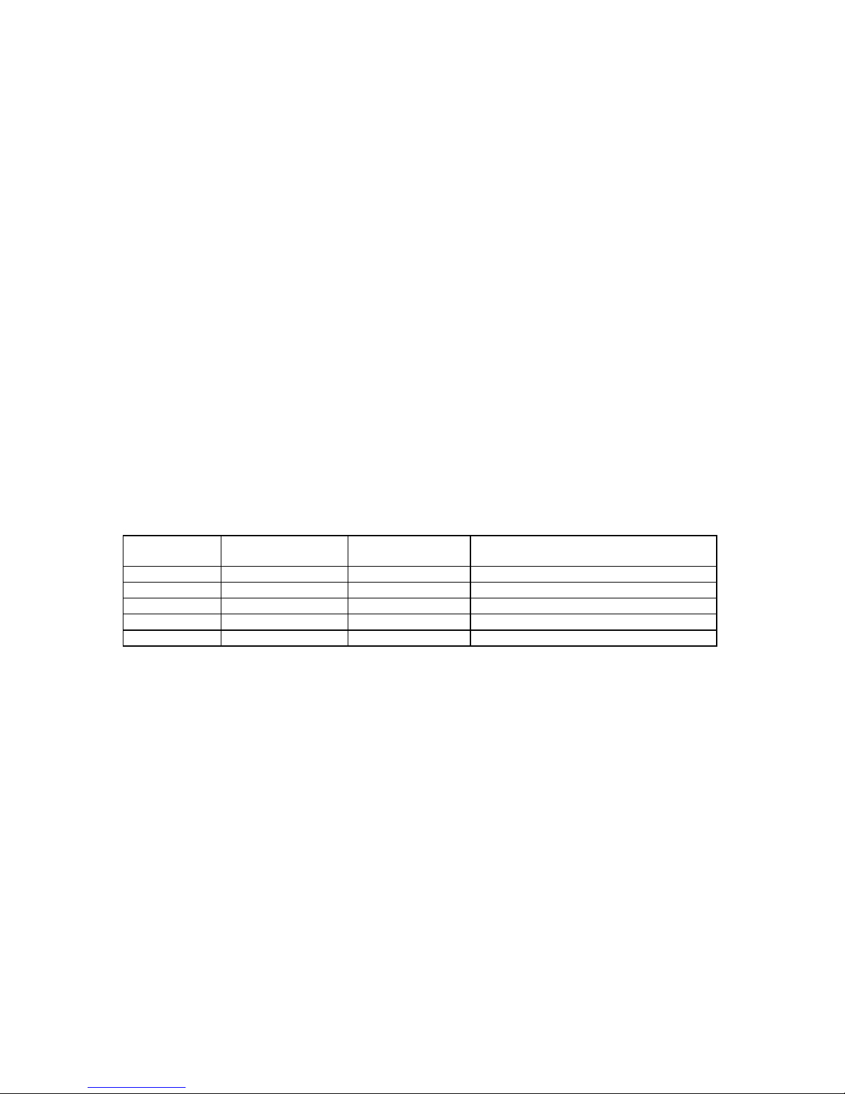
4. Settings / Adjustments
4.1. IDLING CURRENT ADJUSTMENT
Connect the DC-volt meter at the BIAS measuring points (refer to table) and adjust the idling current via the trim
potentiometer (on the printed board assembly 84157). Adjust both channels of the power amplifier A&B.
Setting Measuring point 1 Measuring point 2 U (DC) BIAS trimmer
BIAS HOT A CNSERV 2 CNSERV 3 15 mV VR1
BIAS COLD A CNSERV 5 CNSERV 6 15 mV VR2
BIAS HOT B CNSERV 2 CNSERV 3 15 mV VR1
BIAS COLD B CNSERV 5 CNSERV 6 15 mV VR2
4
Adjusting the idling current has to be performed at normal room temperature. In case the power amplifier had
previously been operated, it has to be given several hours to cool off.
4.2. FLOATING - SYMMETRY
Immediately after setting the idle current, a symmetry check of the floating voltage has to be performed. The
power amplifier has to be operated in idling condition. DC-volt meters have to be connected between the
measuring points 1 - 2, and 2 - 3. Using the FLOATING-trim potentiometers that are located on the printed
board assembly 86207/86211, the floating voltage is set symmetric to the ground potential. Not the actual
voltage value is relevant but the symmetry of the + floating voltage and the - floating voltage to the ground
potential.
Setting Measuring
point 1
Measuring
point 2
Measuring
point 3
U(DC) Trim
potentiometer
FLOTING SYMMETRIE A CNSERV 8
AMP-A
CNSERV 7
AMP-A
CNSERV 9
AMP-A
ca. ± 67V
VR102
FLOTING SYMMETRIE B CNSERV 8
AMP-B
CNSERV 7
AMP-B
CNSERV 9
AMP-B
ca. ± 67V
VR202
4.3. VCA - OFFSET:
Rhythmically open and short-circuit the service switch S101 respectively S201 which are located on the printed
board assembly 86207/86211. Use VR101 respectively VR201 to adjust the power amplifier outputs to their
minimum offset (with oscilloscope to minimal peak value or to the audible minimal volume of the interfering
pulse).
Instead of using the service switch, it is also possible to employ the service connector with short-circuited pins
CNASERV 2 and CNASERV 3 for the power amplifier A, or short-circuited pins CNBSERV 2 and CNBSERV
3 for the power amplifier B.
4.4. ADJUSTING THE METER INSTRUMENTS
• level control set all the way to its clockwise position
• f = 1 kHz
Feed the signal to the inputs A or B so that the IN-LED just lights (U(E) approx. -34 dBu). Adjust the OUT-LED
to approximately the same brightness, using the trim potentiometers VR600 respectively VR601 which are
located on the printed board assembly 86207/86211.
4.5. ADJUSTING THE FANS
Close the service switch S001 on the printed board assembly 86207/86211 or insert a bridge between CNBSERV
5 and CNBSERV 6. Adjust the voltage at CNBSERV 4 to 27.5 V (DC), using the VR700. Switch the service
switch back to normal or detach the bridge.
4.6. GAIN SELECTION:
The power amplifier's input sensitivity can be set using the jumpers J11 … J13 or J21 … J23 which are located
on the printed board assembly 86207/86211. The stated values for the input sensitivity or gain are always
referenced to the level control being set to its fully clockwise position.
CHANNEL A CHANNEL B SELECTION
J11 J21 Input Sensitivity 0 dBu
J12 J22 Input Sensitivity +6 dBu
J13 J23 Gain +26 dB
When shipped, the input sensitivity is set to a value of 0 dBu.
5. Function test
5.1. OUTPUT - offset voltage
DC-voltage measuring at the loudspeaker outputs CHANNEL A/B with U(DC) ≤ ±10 mV.
5.2 LIMITER
5.2.1. Attenuation test
Both channels separately driven with a 1 kHz signal up to U(A) = 89 V (without load). Increase the input voltage
by 10 dB. The LIMITER LED lights and the output voltage ascents by approx. 0.5 dB to 91 volts, with slight
5
clipping. The distortion rate of the limited signal is at THD = 1 % … 2 %. Increasing the input signal up to a
value of +21 dBu should not result in remarkably higher clipping.
5.2.2. LIMITER FAST/SLOW-Test
• tests have to be performed for both channels of the power amplifier individually: testing has to be
performed without load resistors connected.
1.) Drive the power amplifier with a burst signal (f = 1 kHz, 1-10 cycles, rate: ≈ 0.5 sec.) and U(E) =
+10 dB above the nominal input voltage.
2.) When monitoring the output signal via oscilloscope, continuously press the FAST/SLOW-switch.
• SLOW: after 2-3 signal periods, the limiter controlled the major distortion down to a minor residual
distortion (THD = 1 % … 2 %).
• FAST: already after 1-2 signal periods, the limiter controlled the major distortion down to a minor
residual distortion (THD = 1 % … 2 %).
When shipped, the appliance is set to SLOW!
5.3. POWER-ON DELAY:
Approximately 2 seconds after switching the power on, the relays E1 and E3 which are located on the printed
board assembly 86207/86211 and the relay E1 on the printed board assembly 84157 (channel A/B) pull
simultaneously.
5.4. FAN CONTROL:
Upon powering-on the power amplifier, the fans will run for approximately 2 seconds and stop when the power
amplifier has re-gained its "normal" temperature. In idling condition (power-on, no signal present) the fans are
switched between the SLOW and OFF mode, depending on the heat sink's temperature. When the switch S001
on the printed board assembly 86207/86211 is closed, the fans will run with FAST speed. When shipped, the
S001 switch is set to "OPEN"!
Connecting a variable resistor (approx. 50 kΩ) between CNBSERV 5 and CNBSERV 6 allows for testing the
functioning of the fans. During operation, CNASERV 6 can be utilized to monitor the temperature of the heat
sink.
FAN SPEED U(DC)
CNASERV 6
U(DC)
CNBSERV 4
Remarks
Stufe 0 < 6.5 V 0 V Fans are not running
Stufe 1 6.5 V ... 7.5 V 12.5 V
Stufe 2 7.5 V ... 9 V 19.5 V
Stufe 3 9 V ... 12.5 V 27.5 V
Protect > 12.5 V 27.5 V Power amplifier is switched off
5.5. SOAR-PROTECTION TEST:
Channels separately driven up to 69.3 V on 4 Ω. Parallel connect a 0.1 Ω resistor. The protection circuit reacts
and tries continuously to re-start! The protect-LED blinks in the same rhythm.
5.6. SHORT-CIRCUIT CURRENT-LIMITING TEST
testing has to be performed for both channels of the power amplifier individually:
- drive the channel with a burst signal (f = 1 kHz, 1-10 cycles, rate ≈ 1 sec.) without load, with U(A) = 89 V
- connect a load resistor of 1 Ω.
- the short-circuit current-limiter limits the output voltage at the load resistor symmetrically (monitor via
oscilloscope!) to a peak voltage value of 45 V ( approx. 45 A).
5.7. DC-VOLTAGE-PROTECTION TEST
• HI/LO-Cut off, Limiter set to SLOW
testing has to be performed for both channels of the power amplifier individually:
- drive the power amplifier with a test signal (f = 7 Hz) and without load resistor connected.
- at an input voltage of approx. 3 Vpeak the protection circuit reacts and tries continuously to re-start!
The protect-LED blinks with the same frequency.
- Repeat the test with f = 14 Hz; the power amplifier should not switch off.
5.8. HF-PROTECTION TEST
Caution: it is mandatory to drive the power amplifier without load resistors connected. Set the fan service
switch to ON and the HI/LO-Cut to OFF. Switch off the limiter via S102 or by disconnecting the bridge between
CNASERV 1 and CNASERV 3. Drive the power amplifier with a with 7 Vrms and a sine burst of f = 60 kHz
 Loading...