

Page 1
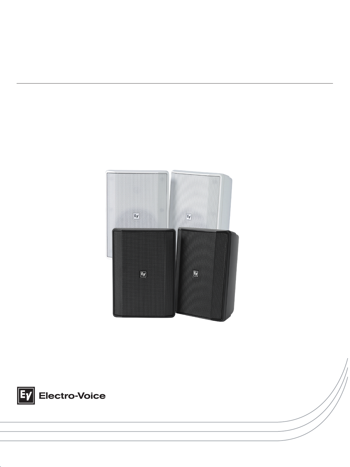
EVID Surface Mount S Series - X Models
EVID-S5.2XB | EVID-S5.2XW
en | Installation manual
Page 2

Page 3

Table of contents
en 3
1
1.1 Suspension 4
1.2 Notices 4
2
2.1 System features 5
2.2 Product information 5
2.3 Packing list 6
3
3.1 Installing the speaker 7
3.2 U-Bracket installation options 8
3.3 Wiring 9
3.4 Transformer taps 10
3.5 Replacing the logo 11
4
5
5.1 Dimensions 14
5.2 Frequency response and impedance 14
Safety 4
Introduction 5
Installation and wiring 7
Troubleshooting 12
Technical data 13
Electro-Voice Installation manual 2017.08 | 01 | F.01U.345.358
Page 4
!
EVID Surface Mount S Series - X Models
1
1.1
Safety
Suspension
Warning!
Suspending any object is potentially dangerous and should only be attempted by individuals
who have a thorough knowledge of the techniques and regulations of suspending objects
overhead. Electro-Voice strongly recommends all loudspeakers be suspended taking into
account all current national, federal, state, and local laws and regulations. It is the
responsibility of the installer to ensure all loudspeakers are safely installed in accordance
with all such requirements. When loudspeakers are suspended, Electro-Voice strongly
recommends the system be inspected at least once per year or as laws and regulations
require. If any sign of weakness or damage is detected, remedial action should be taken
immediately. The user is responsible for making sure the wall, ceiling, or structure is capable
of supporting all objects suspended overhead. Any hardware used to suspend a loudspeaker
not associated with Electro-Voice is the responsibility of others.
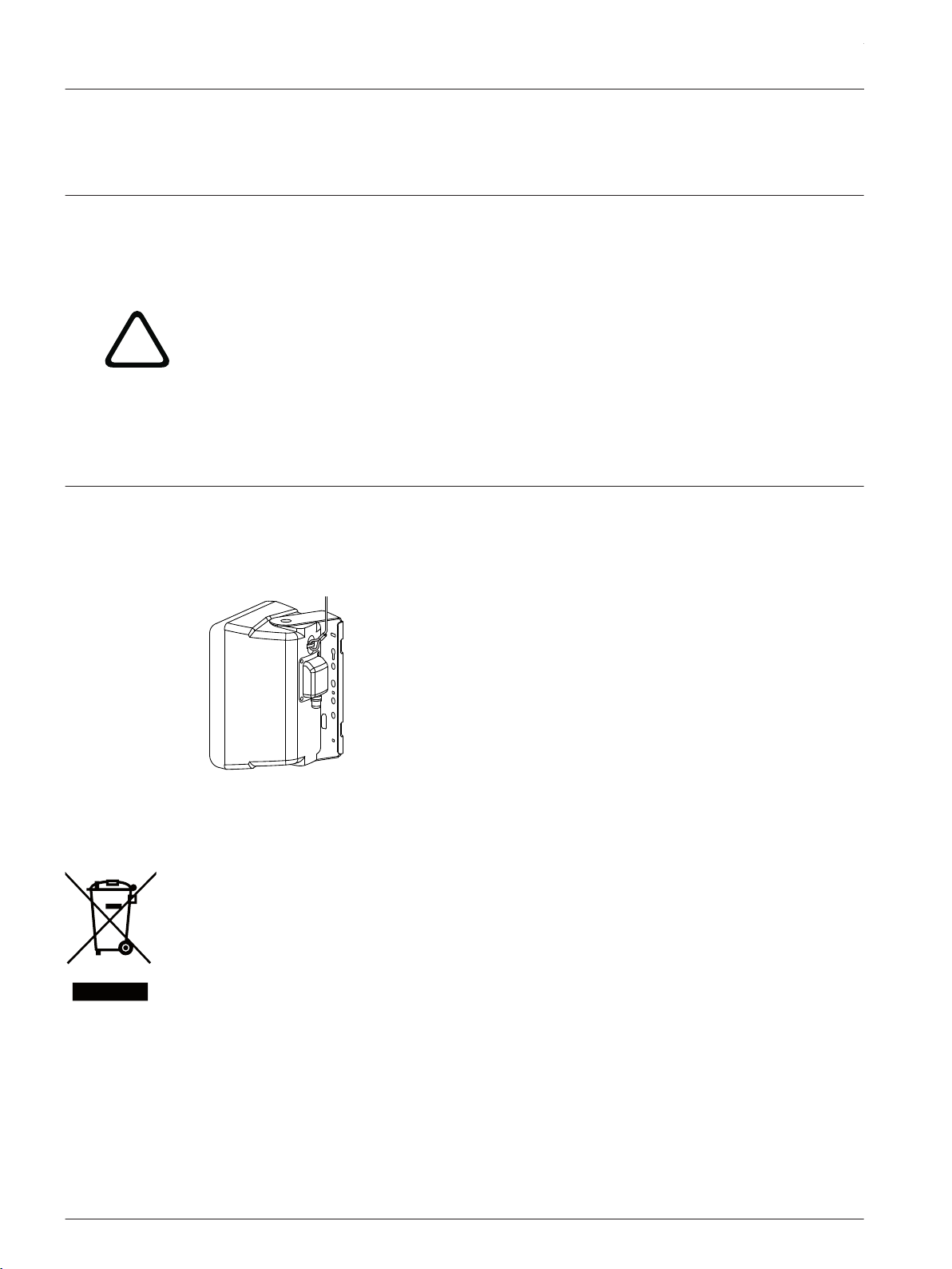
Redundant safety point
As an added safety measure, it is suggested the user install an extra suspension point back to
the building structural supports. This redundant safety point should have as little slack as
possible (less than 1-inch is preferable).
Figure 1.1: Redundant safety point
1.2
2017.08 | 01 | F.01U.345.358 Installation manual Electro-Voice
Notices
Old electrical and electronic appliances
Electrical or electronic devices that are no longer serviceable must be collected separately and
sent for environmentally compatible recycling (in accordance with the European Waste
Electrical and Electronic Equipment Directive).
To dispose of old electrical or electronic devices, you should use the return and collection
systems put in place in the country concerned.
Copyright and disclaimer
All rights reserved. No part of this document may be reproduced or transmitted in any form by
any means, electronic, mechanical, photocopying, recording, or otherwise, without the prior
written permission of the publisher. For information on getting permission for reprints and
excerpts, contact Electro-Voice.
The content and illustrations are subject to change without prior notice.
Page 5
A
C
D
B
E
en 5
2
2.1
Introduction
The EVID-S series, from Electro-Voice, is a line of compact, high-performance, two-way, fullrange surface mount speakers, with excellent wide and uniform coverage, and outstanding
performance. Their design makes these practically invisible for use in background and
foreground music, paging, and sound reinforcement applications, making EVID-S ideal for
indoor and outdoor applications, such as restaurants, bars, patios, retail, fitness clubs,
hospitality, theme parks, leisure venues, and others. With unparalleled ease-of-installation,
sturdy weather resistance, modern and delicate look, and flexible mounting options, the EVIDS series is the perfect solution for a wide variety of surface mount applications.
The EVID-S5.2X models are IP65 rated, designed to withstand the toughest weather
conditions.
Read through this manual to familiarize yourself with the safety information, features, and
applications before you use these products.
System features
▪ Carefully engineered for the toughest weather conditions (IP65)
▪ Long throw 5.25" (133 mm) woofer housed in a UL 94-5VB fire rated ABS plastic for
extended LF performance down to 55 Hz
▪ 90 W power handling provides for 108 dB maximum SPL (114 dB Peak)
▪ 60 W transformer with 8 Ω pass-through
2.2
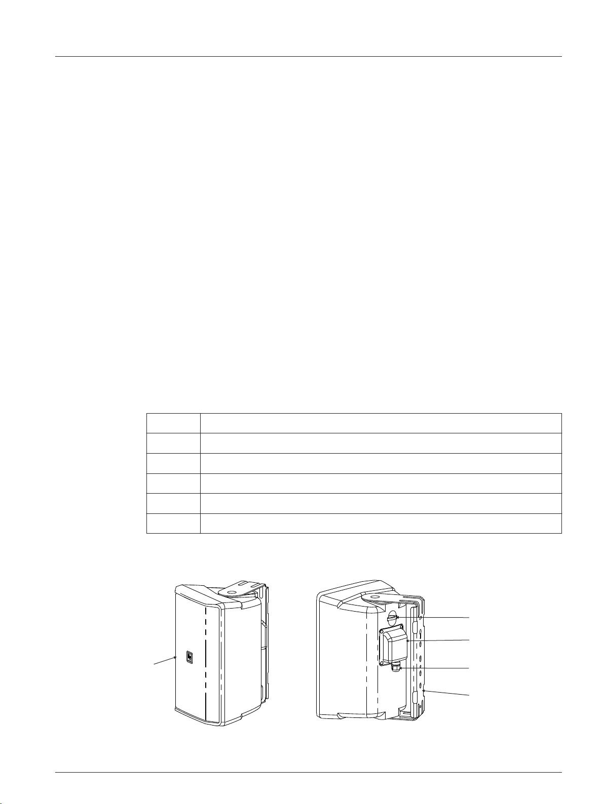
Product information
Item Description
A Grille
B Safety cable loop
C Weather input cover
D Gland nut
E U-Bracket
Table 2.1: Product information
Electro-Voice Installation manual 2017.08 | 01 | F.01U.345.358
Figure 2.1: Product information
Page 6
A (x2)
B
D (x2)
C (x4)
E (x2)
F (x8)
G (x2)
H
EVID Surface Mount S Series - X Models
2.3
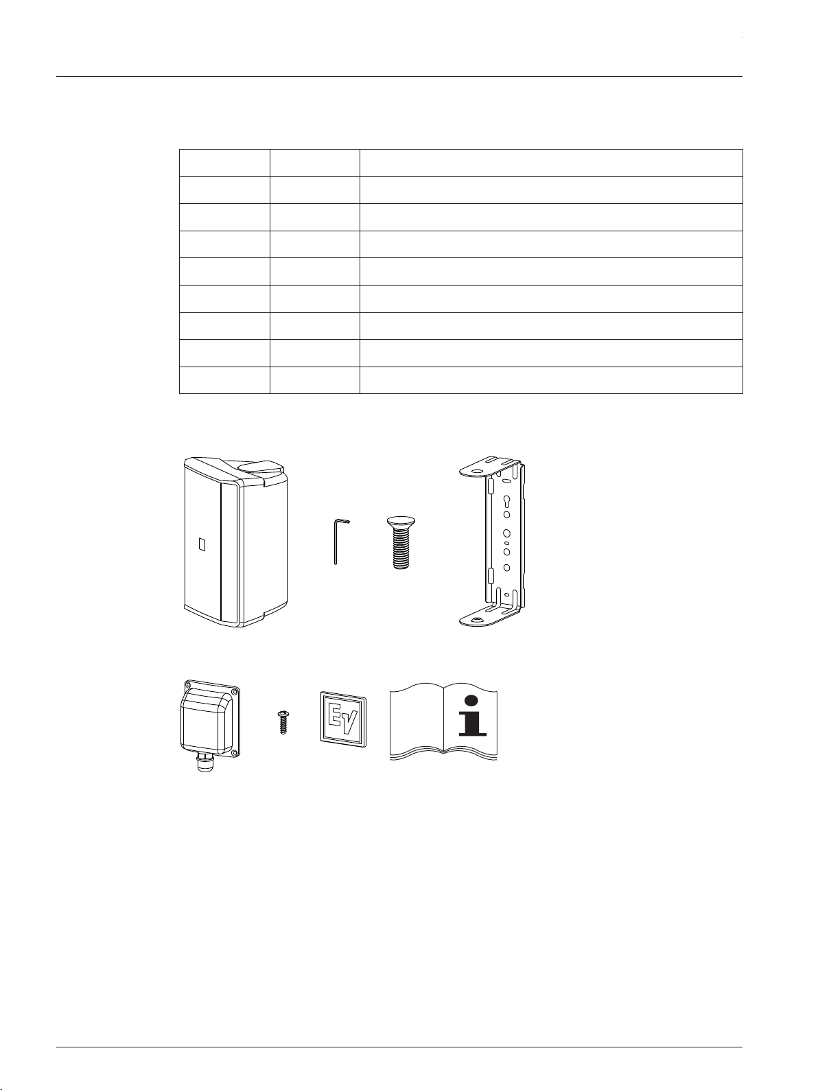
Packing list
Item Quantity Component
A 2 Speakers
B 1 Allen wrench
C 4 Safety screws for the U-Brackets
D 2 U-bracket
E 2 Weather covers
F 8 Weather cover screws
G 2 Grille logos (spares)
H 1 Installation manual
Table 2.2: Components list
Figure 2.2: Components list
2017.08 | 01 | F.01U.345.358 Installation manual Electro-Voice
Page 7
!
en 7
3
3.1
Installation and wiring
Installing the speaker
For safety, ensure the mounting surface supports more than the weight of the speaker. Use
only industry-accepted fasteners and mounting methods when mounting the U-Bracket.
Consult an expert if you are unsure.
Caution!
It is the installer's responsibility to determine and use the proper mounting hardware for
the wall construction type.
Disregarding this caution could result in damage to the product and personal injuries may
occur.
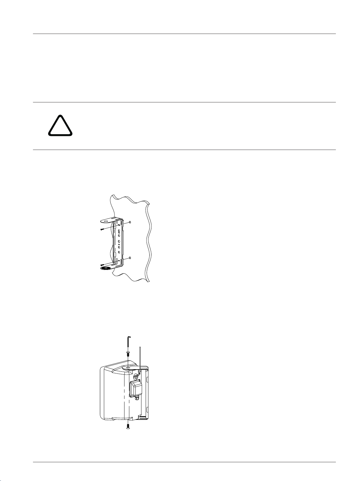
Installing the U-Bracket
To install the U-Bracket, do the following:
1. Draw a level line.
2. Align screw holes on the level line.
3. Install two mounting screws to secure the U-Bracket to the wall.
Installing the speaker
To install the speaker, do the following:
1. Wire the speaker, as shown in the wiring section.
2. Insert the two screws (provided) into the U-Bracket mounting points.
Loosely tighten the two screws using the Allen wrench (provided).
3. Aim the speaker.
Electro-Voice Installation manual 2017.08 | 01 | F.01U.345.358
Page 8
EVID Surface Mount S Series - X Models
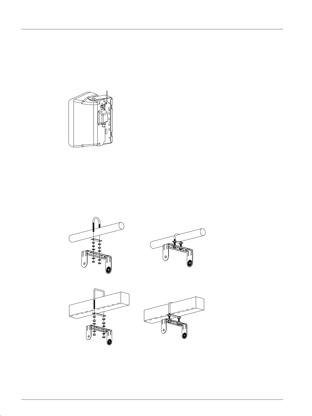
4. Tighten the two screws to secure the U-Bracket to the speaker.
Ensure the speaker is secured to the U-Bracket.
Redundant safety point
As an added safety measure, it is suggested the user install an extra suspension point back to
the building structural supports. This redundant safety point should have as little slack as
possible (less than 1-inch is preferable).
Figure 3.1: Redundant safety point
See also
• U-Bracket installation options, page 8
• Wiring, page 9
3.2
U-Bracket installation options
Using a U-Bolt
The U-Bracket can be mounted using a standard 2-inch or 4-inch U-Bolt.
Figure 3.2: U-Bolt — 2-inch
Figure 3.3: U-Bolt — 4-inch
2017.08 | 01 | F.01U.345.358 Installation manual Electro-Voice
Page 9
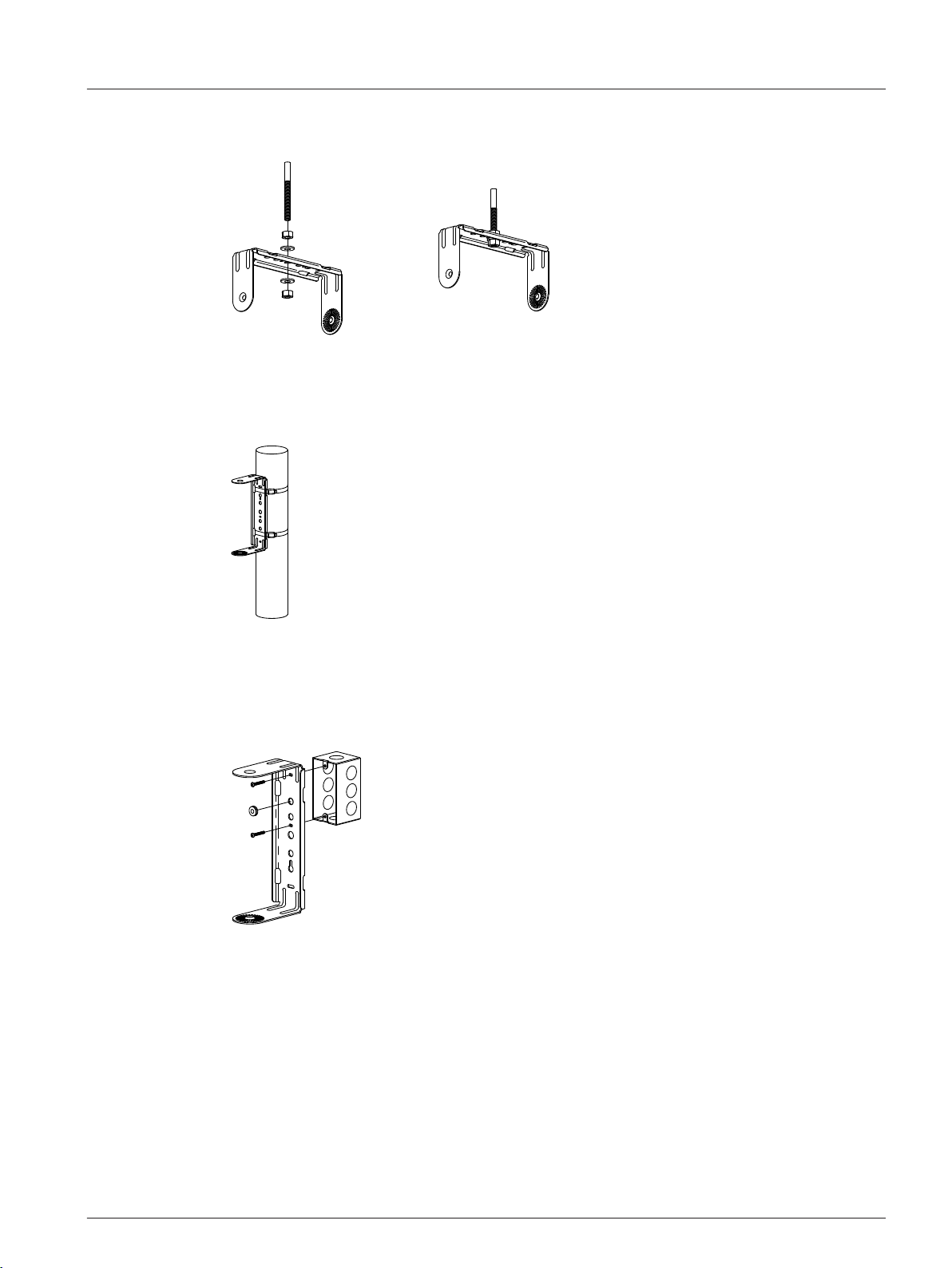
Using a threaded rod
The U-Bracket can be installed to a threaded rod.
Figure 3.4: Threaded rod
Using a pole mount
The U-Bracket can be installed to a pole mount using steel band clamps.
en 9
3.3
Figure 3.5: Pole mount
Using a junction box
The U-Bracket can be installed to a junction box using a 0.25” rubber grommet (not included)
for wiring.
Figure 3.6: Junction box
See also
• Installing the speaker, page 7
Wiring
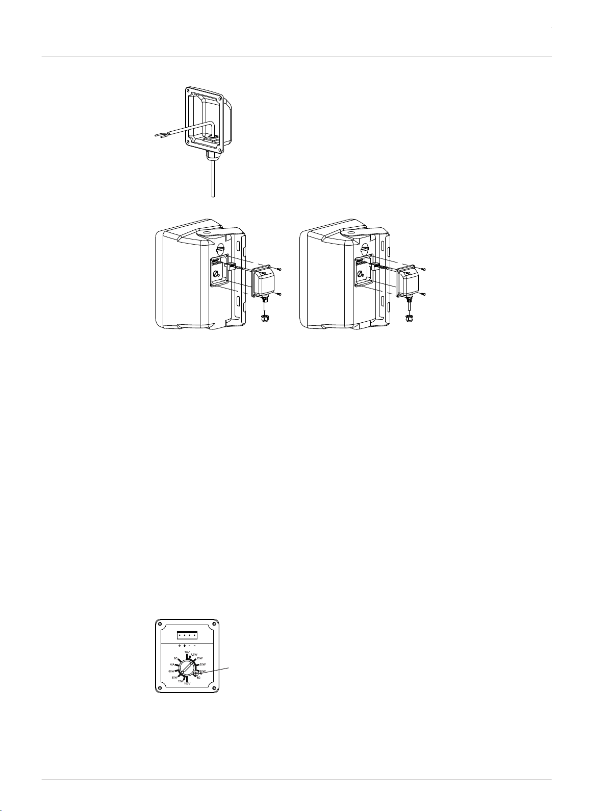
Wiring the speaker
The speaker can be wired using either 2-wires, for input only, or 4-wires, for input and parallel
output. Reference the polarity markers on the Euroblock.
To wire the speaker using the weather cover, do the following:
Electro-Voice Installation manual 2017.08 | 01 | F.01U.345.358
Page 10
A
B
C
A
B
C
+
A
EVID Surface Mount S Series - X Models
1. Push the wire through the gland nut.
2. Wire the Euroblock connector (A).
3.4
3. Adjust the tap settings, if needed.
4. Mount the speaker, as shown in the installation section.
5. Plug the Euroblock connector into the speaker.
6. Insert the four screws into the weather cover (B).
Loosely tighten the four screws to keep the weather cover in place.
7. Tighten all four screws to secure the weather cover.
Ensure the weather cover is secure.
8. Adjust the wire length.
9. Tighten the gland nut (C).
See also
• Installing the speaker, page 7
Transformer taps
You can select the mode of operation (70 V/100 V/8 ohm) and power taps using the rotary
switch on the input panel.
Configuring the transformer settings
To configure the transformer settings, do the following:
1. Select the desired power tap by using the rotary switch on the input panel.
2017.08 | 01 | F.01U.345.358 Installation manual Electro-Voice
Page 11
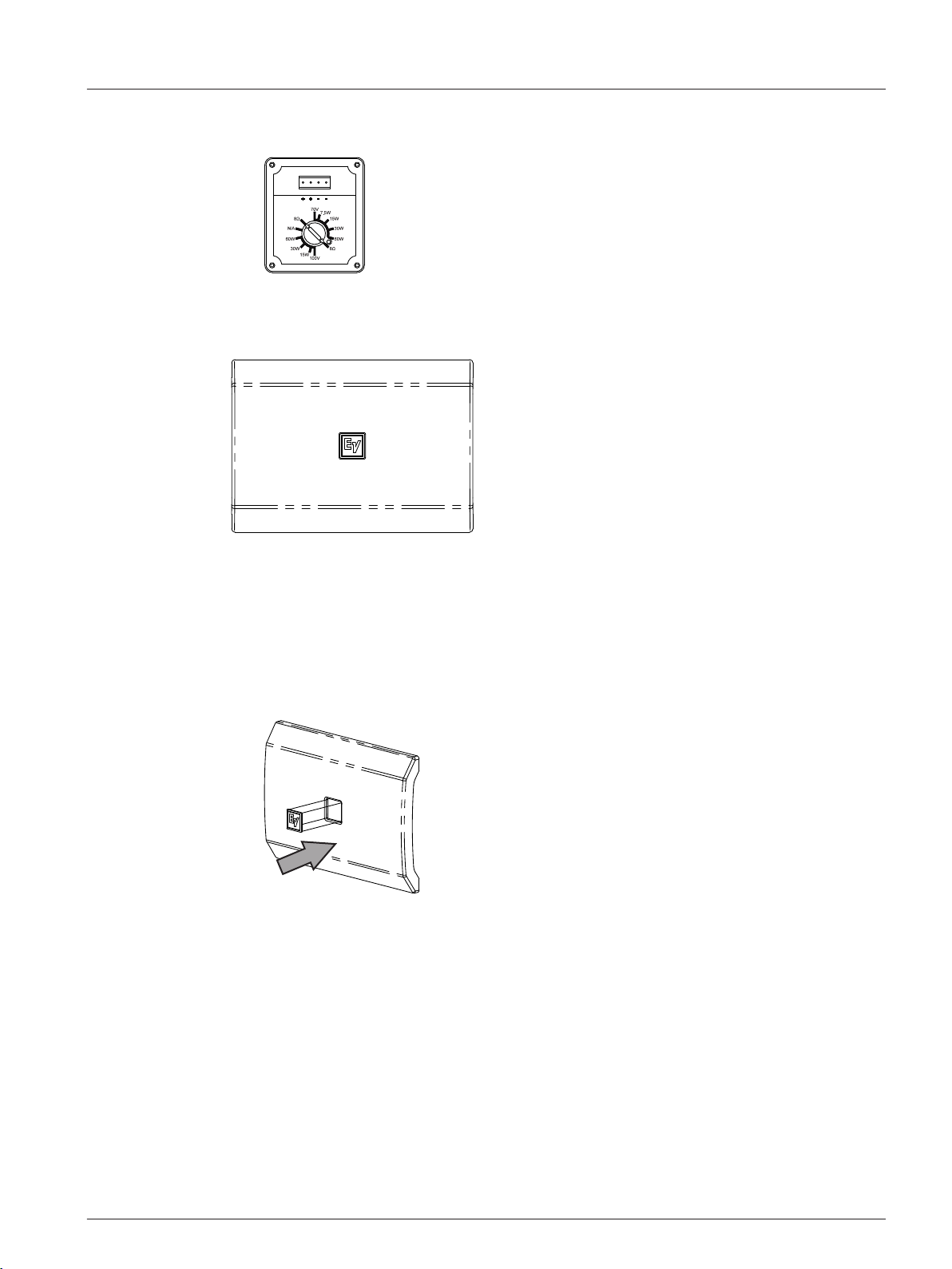
2. If 8 ohm mode is desired, remove the safety screw.
Safety screw (A) is shown in the previous step.
en 11
3.5
Replacing the logo
An additional logo is included, horizontal installation is shown.
replace the logo, do the following:
To
1. Remove the existing logo.
2. Clean the surface with alcohol.
3. Align the logo with the logo recess on the grille.
4. Remove the paper backing.
5. Insert the logo.
Press firmly to ensure the logo is applied.
Electro-Voice Installation manual 2017.08 | 01 | F.01U.345.358
Page 12

EVID Surface Mount S Series - X Models
4
Problem Possible Causes Action
No Sound Amplifier Connect a known working test speaker to the amplifier outputs. If
Troubleshooting
there is no sound, check all electronics are on, the signal routing is
correct, the source is active; the volume is turned up, and so on.
Correct/Repair/Replace as necessary. If there is sound, the problem is
in the wiring.
Wiring Verify you have connected the correct wire pairs to the amplifier. Play
something at low level through the amplifier (for example, from a CD
player or tuner). Connect the test speaker in parallel with the
malfunctioning line. If the sound has gone or is very weak, the line has
a short in it (possibly a severe scrape, pinch, or staple puncture). If
the sound level is normal the wire is open (possibly a cut wire or
missed connection). Using the test speaker, move down the line and
test each connection/junction until you find the problem and correct
it. Observe proper polarity.
Verify you have the inputs and outputs connected to the correct wires.
If the subwoofer input panel is not correctly wired, there will be little
or no sound. Observe proper polarity.
Poor LowFrequency
Response
Intermittent
Output such as,
Crackling or
Distortion
Constant Noise
such as Buzzing,
Hissing, Humming
Speakers Wired Outof-Polarity
Improperly Wired
Subwoofer Panel
Faulty Connection Check all connections at amplifier and speakers to ensure they are
Defective Amplifier
or other Electronic
Device
Poor System
Grounding or
Ground Loop
If these suggestions do not solve your problem, contact your nearest Electro-Voice dealer or
Electro-Voice distributor.
When two speakers are connected out of polarity (out of phase), the
low frequencies will cancel each other acoustically. Carefully observe
the wire markings or tracers on your speaker wires. Verify the
amplifier (+) terminal is connected to the red speaker terminals and
the amplifier (-) terminal is connected to the black speaker terminals.
Using a test speaker as described above, verify all amplifier and
speaker wires are connected to their proper terminals with the correct
polarity. Reversing just one set of amplifier wires can cut out all bass
output from the subwoofer.
clean and tight. If the problem persists, it may be in the amplifier or
wiring. See other actions above.
If the noise is present but no program material is playing, the likely
cause is the signal chain in the electronics. Evaluate each component
as necessary to isolate the problem.
Check and correct the system grounding, as required.
2017.08 | 01 | F.01U.345.358 Installation manual Electro-Voice
Page 13

en 13
5
Technical data
Frequency response (-3 dB): 90 Hz – 20 kHz
Frequency response (-10 dB) 55 Hz – 20 kHz90 Hz – 20 kHz
Sensitivity: 89 dB
Max SPL (calculated): 108 dB, 114 dB Peak
Coverage angle: Horizontal 90°, Vertical 90°
Power handling: 90 W (360 W Peak) Continuous Pink Noise (100 h)
Nominal impedance: 8 Ω
Minimum impedance: 6.4 Ω
Recommended high-pass: 60 Hz (24 dB/octave)
Input transformer (70 V/100 V): 60 W
Transformer taps: 70V: 60 W, 30 W, 15 W, 7.5 W, 8Ω
Low frequency transducer: 5.25 in (1.22 mm)
2
Low Z: Yes
100V: 60 W, 30 W, 15 W, 8Ω
High frequency transducer: 0.75 in (20 mm)
Connectors: Removable locking 4-pin connector (Euroblock) – (2)
for connection to additional speakers in a distributed
line.
Max. wire size 12AWG (2.5 mm)
Environmental: IP-65 (per IEC-60529)
Color: Black (RAL 9003) or white (RAL 9004)
Dimensions (HxWxD): 255 mm x 180 mm x 148 mm (10.0 in x 7.1 in x 5.8
3
in)
Net weight: 3.2 kg (7.1 lb)
Shipping weight: 9.5 kg (21.0 lb)
Included hardware: U-Bracket, 5-mm Allen wrench and input cover
Packaged quantity: 2
1
Half space (wall mounting).
2
Half space (on wall) averaged 100 Hz – 10 kHz, 1 W.
3
Without U-Bracket.
3
Electro-Voice Installation manual 2017.08 | 01 | F.01U.345.358
Page 14
180.0 mm
[7.09 in]
255.0 mm
[10.04 in]
193.0 mm
[7.60 in]
148.0 mm
[5.83 in]
169.0 mm
[6.65 in]
EVID Surface Mount S Series - X Models
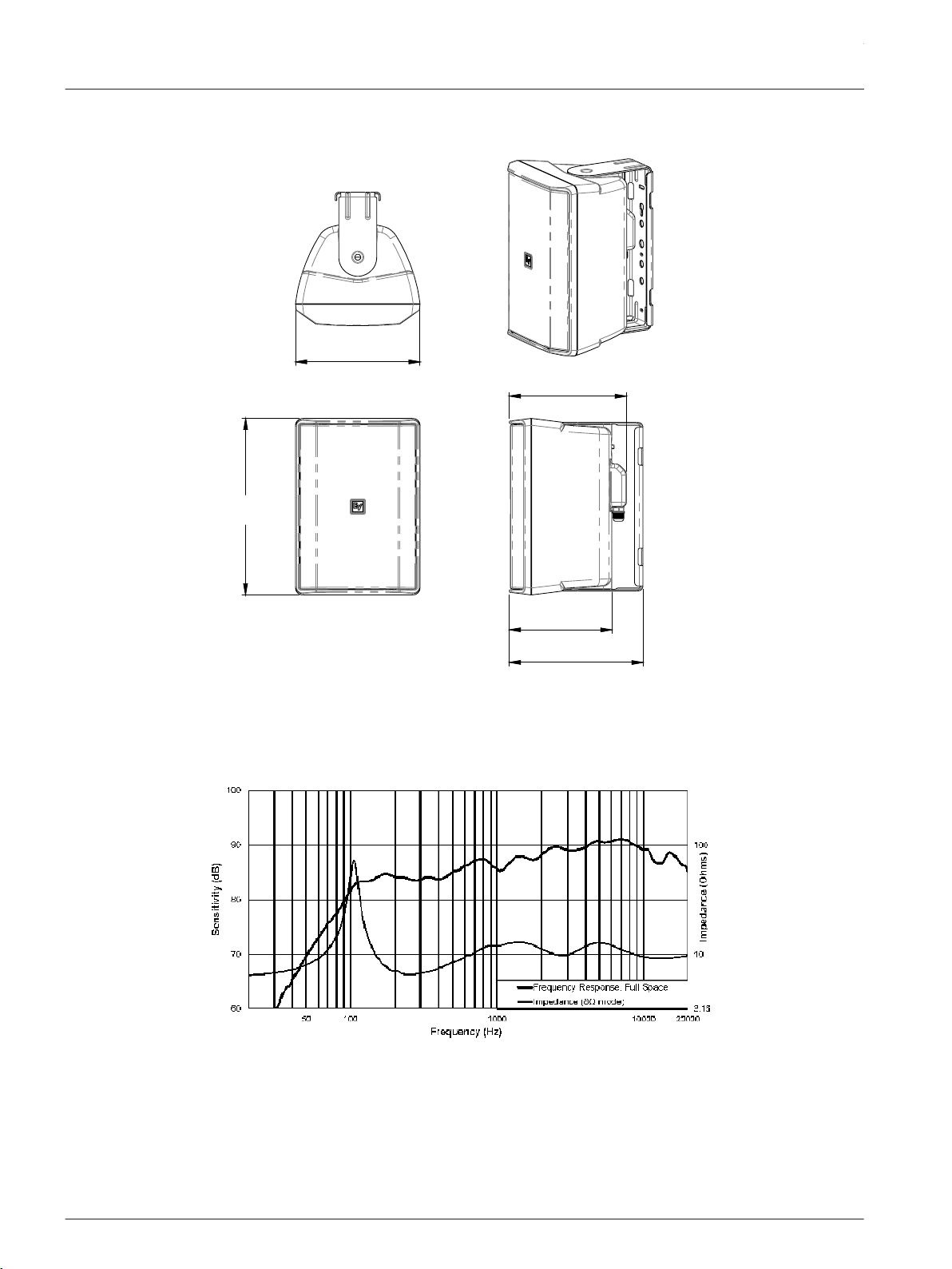
5.1
Dimensions
5.2
Figure 5.1: EVID-S5.2X dimensions
Frequency response and impedance
Figure 5.2: EVID-S5.2X frequency response and impedance
2017.08 | 01 | F.01U.345.358 Installation manual Electro-Voice
Page 15

Page 16

Bosch Sicherheitssysteme GmbH
Robert-Bosch-Ring 5
85630 Grasbrunn
Germany
www.boschsecurity.com
© Bosch Sicherheitssysteme GmbH, 2017
Bosch Security Systems, Inc
12000 Portland Avenue South
Burnsville MN 55337
USA
www.electrovoice.com
 Loading...