


SERVICE MANUAL
Dx 38
24 BIT DIGITAL SOUND SYSTEM PROCESSOR

WARRANTY (Limited)
Electro-Voice products are guaranteed against malfunction due to defects in materials or workmanship for a specified period, as noted in the individual product-line statement(s) below, or in the individual product data sheet or owner’s manual, beginning with the date of original purchase. If such malfunction occurs during the specified period, the product will be repaired or replaced (at our option) without charge. The product will be returned to the customer prepaid.
Exclusions and Limitations: The Limited Warranty does not apply to: (a) exterior finish or appearance; (b) certain specific items described in the individual product-line statement(s) below, or in the individual product data sheet or owner’s manual; (c) Malfunction resulting from use or operation of the product other than as specified in the product data sheet or owner’s manual; (d): malfunction resulting from misuse or abuse of the product; or (e): malfunction occurring at any time after repairs have been made to the product by anyone other than Electro-Voice or any of its authorized service representatives.
Obtaining Warranty Service: To obtain warranty service, a customer must deliver the product, prepaid, to Electro-Voice or any of its authorized service representatives together with proof of purchase of the product in the form of a bill of sale or receipted invoice. A list of authorized service representatives is available from Electro-Voice at 600 Cecil Street, Buchanan, MI 49107 (616-695-6831) and/or Electro-Voice West at 9130 Glenoaks Boulevard, Sun Valley, CA 91532 (213-875-1900).
Incidental and Consequential Damages Excluded: Product repair or replacement and return to the customer are the only remedies provided to the customer. Electro-Voice shall not be liable for any incidental or consequential damages including, without limitation, injury to persons or property or loss of use. Some states do not allow the exclusion or limitation of incidental or consequential damages so the above limitation or exclusion may not apply to you. Other Rights: This warranty gives you specific legal rights, and you may have other rights which vary from state to state.
Electro-Voice Electronics are guaranteed against malfunction due to defects in materials or workmanship for a period of three (3) years from the date of original purchase. Additional details are included in the Uniform Limited Warranty Statement.
Specifications subject to change without notice.
600 Cecil Street, Buchanan, Michigan 49107, Phone 616/695-6831, Fax: 616/695-1304
TELEX/EVI Audio Canada, 705 Progress Ave. Unit 46 Toronto, Onatario, M1H 2x1, Canada , Phone: 800/881-1685, Fax: 877/522-2242 TELEX Communications A.G., Keltenstrasse 11, CH-2563 IPSACH, Switzerland, Phone: 011-41/32-51-6833, Fax: 011-41/32-51-1221
EVI Audio Deutschland GmbH, Hirschberger Ring 45, D-94315, Straubing, Germany, Phone: 011-49/9421-7060, Fax: 011-49/9421-706265
EVI Audio France S.A., Parc de Courcerin-Allee Lech Walesa, Lognes, f-77185 Marne La Vallee, France, Phone: 011-33/1-6480-0090, Fax: 011-33/1-6006-5103 EVI Audio Japan Ltd., 2-5-60 Izumi, Suginami-ku, Tokyo, Japan 168, Phone: 011-81/3-3325-7900, Fax: 011-81/3-3325-7789
EVI Audio (Aust.) Pty., Unit 24, Block C, Slough Business Park, Slough Ave., Silverwater, N.S.W 2141, Australia, Phone 011-61/2-648-3455, Fax: 011-61/2-648-5585
EVI Audio (Hong Kong) Limited, Unit E & F, 21 /F., Luk Hop Industrial Bldg., 8 Luk Hop St., San Po Kong, Kowloon, Hong Kong, Phone: 011-852/351-3628, Fax: 011 -852/351-3329
Table of Contents
-Safety and Service Instructions
-Warranty
-
-Architects and engineers specifications
-Measuring data
-
-Bill of materials
-Service notes / infos / instructions
-Spare parts plan
-
- Circuit diagrams
Electro-Voice
600 Cecil Street,
Buchanan,
Michigan 49107
Phone 616/695-6831 Fax 616/695-1304 e-mail fspain@qtm.net

IMPORTANT SAFETY INSTRUCTIONS
The lightning flash with arrowhead symbol, within an equilateral triangle is intended to alert the user to the presence 
 of uninsulated “dangerous voltage” within the product’s
  enclosure that may be of sufficient magnitude to constitute a risk of electric shock to persons.
The exclamation point within an equilateral triangle is intended to alert the user to the presence of important operating and maintance (servicing) instructions in the literature accompanying the appliance.
1.Read these instructions.
2.Keep these instructions.
3.Heed all warnings.
4.Follow all instructions.
5.Do not use this apparatus near water.
6.Clean only with a damp cloth.
7.Do not block any of the ventilation openings.
Install in accordance with the manufactures instructions.
8.Do not install near any heat sources such as radiators, heat registers, stoves, or other apparatus that produce heat.
9.Only use attachments/accessories specified by the manufacturer.
10.Refer all servicing to qualified service personnel. Servicing is required when the apparatus has been
damaged in any way, such as power-supply cord or plug is damaged, liquid has been spilled or objects have fallen into the apparatus, the apparatus has been exposed to rain or moisture, does not operate normally, or has
been dropped.
For US and CANADA only:
Do not defeat the safety purpose of the grounding-type plug. A grounding type plug has two blades and a third grounding prong. The wide blade or the third prong are provided for your safety. When the provided plug does not fit into your outlet, consult an electrican for replacement of the absolete outlet.
IMPORTANT SERVICE INSTRUCTIONS
CAUTION: These servicing instructions are for use by qualified personnel only. To reduce the risk of electric shock, do not perform any servicing other than that contained in the Operating Instructions unless you are qualified to do so. Refer all servicing to qualified service personnel.
1.Security regulations as stated in the EN 60065 (VDE 0860 / IEC 65) and the CSA E65 - 94 have to be obeyed when servicing the appliance.
2.Use of a mains separator transformer is mandatory during maintenance while the appliance is opened, needs to be operated and is connected to the mains
3.Switch off the power before retrofitting any extensions, changing the mains voltage or the output voltage.
4.The minimum distance between parts carrying mains voltage and any accessible metal piece (metal enclosure), respectively between the mains poles has to be 3 mm and needs to be minded at all times.
The minimum distance between parts carrying mains voltage and any switches or breakers that are not connected to the mains (secondary parts) has to be 6 mm and needs to be minded at all times.
5.Replacing special components that are marked in the circuit diagram using the security symbol (Note) is only permissible when using original parts.
6.Altering the circuitry without prior consent or advice is not legitimate.
7.Any work security regulations that are applicable at the location where the appliance is being serviced have to be strictly obeyed. This applies also to any regulations about the work place itself.
8.All instructions concerning the handling of MOS - circuits have to be observed.
Note: |
SAFETY COMPONENT (HAS TO BE REPLACED WITH ORIGINAL PART ONLY) |
1-2
BESCHREIBUNG
Mit 48 Bit Filteralgorithmen, 24 Bit AD/DA Wandlern und einem Dynamikbereich von 115 dB setzt der Dx 38 neue Maßstäbe für digitale Lautsprecher Kontroller und Prozessoren. Der Dx 38 ist ein universell einsetzbarer Digitaler Sound System Processor mit 2 Eingängen und 4 Ausgängen, sowie zusätzlich einer internen Summe der Eingänge 1 und 2. Die Ausgänge können in einer Matrix auf einen beliebigen Eingang oder die Eingangssumme geroutet werden. Es können Stereo bzw. Dual 2-Weg-Systeme oder 3-Weg+Direct und 4-Weg Systeme, jeweils auch mit Mono Sub-Kanal, aber auch Fullrange Systeme konfiguriert werden.
In allen Betriebsarten stehen Hochund Tiefpaß-Filter für die Frequen- zweichen-Funktionen zur Verfügung. Die Auswahl umfaßt LinkwitzRiley, Butterworth und Bessel Filter mit wählbaren Flankensteilheiten von 6, 12, 18 oder 24 dB/Okt. Eine große Anzahl weiterer Filter ermöglicht eine äußerst flexible Frequenzgangskorrektur. In den Eingängen finden Sie jeweils einen 5-Band Equalizer, dessen einzelne Filtersektionen beliebig mit Highund Low-Pass, Highund Low-Shel- ving oder parametrischen Peak-Dip-Filtern belegt werden können. In den Ausgängen sind neben den Frequenzweichen-Filtern jeweils 4 weitere Filter enthalten, die ebenfalls als Highund Low-Pass Filter, Highoder Low-Shelving-Filter, parametrische Peak-Dip-Filter, oder Allpass-Filter programmiert werden können. Weitere Filtermöglichkeiten sind z. B. Hochpässe 2. Ordnung zur Realisierung von B-6 Alignments, oder spezielle LPN-Filter (Lowpass Notch / Tiefpaß-Sperrfilter) zur Korrektur des Frequenzund Phasengangs von Baßreflexboxen. Zusätzlich ist jeder Kanal mit einem Delay, einem Polaritätswahlschalter, einem programmierbaren Pegelsteller und einem digitalen Kompressor / Limiter ausgestattet. In den Eingängen befinden sich außerdem noch die Master-Delays.
Der Anwender hat die Wahl zwischen zwei Bedien-Modi: Im einfachsten Fall (No Edit Mode) brauchen nur die verwendeten Lautsprecherkombinationen aus der Liste der Factory Preset Programme ausgewählt werden. Das Gerät ist danach optimal auf die Audioanlage eingestellt und sofort betriebsbereit. Im Full Edit Mode hingegen besteht Zugriff auf sämtliche Parameter, so daß beliebige Einstellungen programmiert und gespeichert werden können. Es stehen insgesamt 80 Programmplätze - 50 für die Factory Presets, und weitere 30 für frei programmierbare User-Programme - zur Verfügung.
Die AD/DA-Wandlung im Dx 38 erfolgt mit linearen 24 Bit Wandlern, wobei es sich in der AD-Sektion um gainranging Sigma-Delta-Wandler mit 128-fachem Oversampling handelt. Im DA-Bereich wird mit SigmaDelta Wandlern mit 128-fachem Oversampling gearbeitet. Die Signalverarbeitung erfolgt auf zwei 24 Bit Motorola Signalprozessoren.
Technische Informationen
Architects and engineers specifications
Dx 38
24 BIT DIGITAL SOUND
SYSTEM PROCESSOR
Weitere Merkmale sind:
-FLASH Speicher für Software und Preset Updates über serielle Schnittstellen
-PC Bedienund Konfigurationssoftware unter Windows 95 / Windows 98
-MIDI-Schnittstelle standardäßig
-RS-232, RS-485 Schnittstellen oder Umschaltkontakte optional
-Grafik-Display mit 122 x 32 Dots, hintergrundbeleuchtet
-Einund Ausgänge elektronisch symmetrisch in XLR
-Trafosymmetrierung für die Eingänge optional
-Input / Output Pegelsteller, Output Mute Schalter, KanalFunktionsanzeigen SUB, LO, MID, HI
-Input / Output Aussteueranzeigen, Kompressorund Clip-LED’s
DESCRIPTION
Providing 48-bit filter algorithms, 24-bit AD/DA conversion and a dynamic range of 115 dB, the Dx 38 sets new standards for digital loudspeaker controllers and processors. The Dx 38 is an universal Digital Sound System Processor that provides 2 inputs and 4 outputs; plus internal summing of the inputs 1 and 2. Via matrix it is possible to assign the outputs to any input or to the sum of the inputs. It is further possible to establish the following configurations: Stereo or Dual 2-Way systems, 3-Way + Direct and 4-Way systems, each with Mono Sub-channel, but also full range systems.
High and low-pass filters are provided for the frequency crossover functions in all operation modes. The selection includes Linkwitz-Ri- ley, Butterworth and Bessel type filters with switchable slopes between 6, 12, 18 and 24 dB/oct. A huge number of additional filters offers extremely flexible correction of the frequency response. Each input incorporates a 5-band equalizer, allowing to assign high and low-pass, high and low-shelving or parametric peak-dip filters to its individual filter sections. Next to the frequency crossover filters, four additional filters are employed in each output channel, which also can be set to work as high or low-pass, high or low-shelving filters, parametric peak-dip filters, or all-pass filters. Additional filtering is provided through 2. order high-passes for the realization of B-6 alignment, or special LPN-filters (Low-Pass Notch filters) for correcting the frequency and phase responses of optimally vented woofer cabinets. Each channel additionally provides a delay, a polarity switch, a programmable level control and a digital compressor / limiter while the master delays are located in the input channels.
The user can choose between two operation modes: the “No Edit Mode” allows to simply select the required combination of loudspeaker systems from the factory preset program list. Afterwards, the appliance is optimally matched to the sound system and can be operated instantly. The “Full Edit Mode” on the other hand offers access to all parameters, allowing to freely program and store basically any setting. A total number of 80 memory addresses - 50 preset and 30 freely assignable user-programs - are available.
Within the Dx 38, AD/DA conversion is taken care of by linear 24-bit converters; where the AD-section employs 128 times oversampling, gain-ranging Sigma-Delta converters. The DA-section offers 128 times oversampling Sigma-Delta converters. The overall signal processing is performed by two 24-bit Motorola signal processors.
Additional features are:
-FLASH memory for software and preset updates via serial interfaces
-PC-based operation and configuration software running under Windows ‘95 / Windows ‘98
-Standard MIDI-interface
-RS-232, RS-485 interfaces or switching contacts optionally available
-Back-lit graphic-display with 122 x 32 dots
-Inputs and outputs are electronically balanced, XLR-type connectors
-Input transformer-balancing is optionally available
-Input / Output level controls, Output-Mute switch, channel function indicators SUB, LO, MID, HI
-Input / Output meter instruments, compressor and clipping LEDs
DESCRIPTION
Avec ses algorithmes de filtrage travaillant en 48 bits, ses convertisseurs A/N et N/A 24 bits et sa gamme dynamique de 115 dB, le Dx 38 définit de nouveaux standards dans le domaine des contrôleurs et processeurs numériques de haut-parleurs. Le Dx 38 est un processeur numérique de diffusion universel ; il est pourvu de 2 entrées et 4 sorties, un circuit interne permettant de sommer les entrées 1 et 2. Une matrice permet d’assigner les sous-bandes du signal d’entrée stéréo (ou sommé en mono) à n’importe quelle(s) sortie(s). D’origine, les configurations suivantes sont disponibles : systèmes stéréo 2 voies, mono 2 voies, 3 voies + sortie directe, ou système mono 4 voies, tous offrant éventuellement une sortie mono pour canal Subwoofer et une sortie “large bande”.
Dans tous les modes de fonctionnement, ce sont des filtres passe-haut et passe-bas qui se chargent de répartir le spectre audio en plusieurs bandes de fréquences (crossover). Ces filtres peuvent être de type Linkwitz-Riley, Butterworth ou Bessel, avec des pentes commutables entre 6, 12, 18 et 24 dB/octave. De nombreux autres correcteurs permettent de modeler la courbe de réponse à votre guise : chaque entrée possède par ailleurs cinq correcteurs, pouvant être un filtre passe-haut ou passe-bas, un correcteur d’aigus ou de graves de type Shelve (en plateau), ou un filtre paramétrique. Une fois le signal d’origine réparti en plusieurs bandes, quatre autres correcteurs peuvent prendre place sur chaque canal de sortie : eux aussi peuvent travailler en modes passe-haut ou passe-bas, correcteur d’aigus ou de graves de type Shelve (en plateau), filtre paramétrique, voire filtre passe-tout. Des fonctions de filtrage supplémentaires sont encore prévues, sous la forme de filtres passe-haut du second ordre permettant la réalisation d’alignements de type B-6, ou des filtres spéciaux de type LPN (pour Low-Pass Notch, filtres passe-bas de type Notch) permettant de corriger la réponse en fréquence et en phase d’enceintes de graves travaillant en bass-reflex.
Chaque canal offre en plus un délai, un inverseur de phase, un réglage de niveau programmable et un compresseur/limiteur numérique, les délais principaux se trouvant au niveau des canaux d’entrée.
Deux modes de fonctionnement sont à la disposition de l’utilisateur : le mode “No Edit”, qui ne permet que de sélectionner la combinaison d’enceintes désirée dans la liste donnée par le Programme Preset d’usine. Dans ce cas, l’appareil est configuré de façon optimale en fonction de l’installation, et peut être exploité instantanément. Enfin, le mode “Full Edit”, lui, permet d’accéder à tous les paramètres, ce qui permet de programmer en toute liberté et de mémoriser ses Programmes. L’appareil compte 80 emplacements mémoire - 50 pour les Programmes Presets d’usine et 30 pour les Programmes utilisateur.
À l’intérieur du Dx 38, les conversions A/N et N/A s’effectuent en 24 bits linéaires (Delta-Sigma, suréchantillonnage 128 fois), et les traitements du signal sont calculés par deux DSP Motorola 24 bits.
Parmi les autres caractéristiques :
-Mémoire FLASH pour le logiciel d’exploitation et les Presets, ce qui permet la mise à jour via interface série.
-Logiciel de configuration et de commande pour PC, tournant sous Windows 95/98.
-Interface MIDI Standard.
-En option, commande via interfaces RS-232, RS-485 ou commutation par contacts.
-Affichage graphique rétro-éclairé, 122 x 32 points.
-Entrées et sorties sur XLR, symétrie électronique.
-En option, symétrisation par transformateur d’entrée.
-Potentiomètres de réglage des niveaux d’entrée et de sortie, commutateur de coupure des sorties (Mute) indicateurs SUB, LO, MID, HI par canal.
-Visualisation par VU-mètres des entrées/sorties, du compresseur, LED d’écrêtage.
TECHNICAL SPECIFICATIONS |
|
|
Mains voltage |
90 - 250 V AC / 50 - 60 Hz |
|
Power consumption |
20 watts |
|
Safety class |
I |
|
Inputs |
2 x XLR IN, electronically balanced, |
|
|
transformer optional available |
|
|
2 x XLR OUT (Direct Out) |
|
Input voltage (nominal) |
1.55 V / + 6 dBu |
|
Max. input voltage |
24.5 V / + 30 dBu |
|
Input impedance |
20 kohms |
|
Common mode rejection |
> 40 dB |
|
AD-conversion |
24-bit, Sigma-Delta, 128 times |
|
|
oversampling, linear phase |
|
Outputs |
4 x XLR OUT, electronically balanced |
|
Output voltage (nominal) |
1.55 V / + 6 dBu |
|
Max. output voltage |
8.7 V / + 21 dBu |
|
Output impedance |
< 100 ohms |
|
Min. load impedance |
600 ohms |
|
DA-conversion |
24-bit, Sigma-Delta, 128 times |
|
|
oversampling |
|
Frequency response |
20 Hz - 20 kHz (- 0.5 dB) |
|
S/N ratio |
115 dB (typical) |
|
Distortion without transformer |
< 0.01 % |
|
Distortion with transformer |
< 0.05 % |
|
Frequency crossovers |
6, 12, 18, 24 dB/oct. slope; |
|
|
Butterworth, Bessel, Linkwitz-Riley |
|
Filters |
26 parametric equalizers |
|
|
Low-Shelving equalizer, |
|
|
LPN (Lowpass-Notch) switchable |
|
|
Hi-Shelving equalizer, 6 / 12 dB slope |
|
|
switchable, Lo-Cut filter (B-6 alignment |
|
|
switchable), Hi-Cut filter, All-Pass filter |
|
Compressor / limiter |
4 digital compressors / limiters |
|
Delay |
3 master delays (2 ms - 900 ms) |
|
|
4 channel delays (0 ms - 900 ms) |
|
|
delay-increment 21 µsec. |
|
Data format |
24-bit linear AD / DA conversion, |
|
|
48-bit processing |
|
Sampling rate |
48 kHz |
|
MIDI IN / OUT / THRU |
Data Dump, Master / Slave operation, |
|
|
Remote Control |
|
Display |
122 x 32 Dots, graphic LC-Display with |
|
|
LED-background lighting |
|
Dimensions |
483 x 43.6 x 374 (WxHxD in mm), 19", 1 HU |
|
Weight |
5 kg / 11 lbs |
|
Locking function |
Protection against inadvertent operation |
|
|
via function-lock |
|
Accessories |
PA 1 plexiglas cover 1 HU |
|
Options |
NRS 90244 |
Input transformer |
|
NRS 90247 |
RS-485 interface |
|
NRS 90246 |
Contact Closure interface |
Measuring data Dx 38 – complete device
1.Power Supply
1.1 |
Operation Voltage |
U Mains |
|
|
1.2 |
Operation Current |
at U Mains |
= |
110 V AC |
|
|
at U Mains |
= |
230 V AC |
1.3Power Consumption
1.4Internal Operation Voltage
1.5 |
Internal Operation Currents |
+5 V |
|
|
+18 V |
|
|
-18 V |
1.6Power Supply Switching Frequency
2.Inputs
2 x XLR IN, electronically balanced, 2 x XLR Direct Out, Input transformers (NRS 90244) are optionally available
2.1 |
Input Impedance |
electronically balanced |
2.2Input Voltage [1] Max. Input Voltage
2.3 Common Mode Rejection |
CMRR |
3.Outputs
4 x XLR OUT, electronically balanced
3.1Output Impedance
3.2Min. Load Impedance
3.3Max. Output Voltage [1]
3.4Output Symmetry [1] [2]
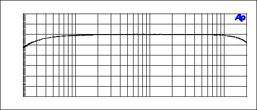
4.Frequency Response
4.1Frequency Response [3] fig. 1
5.Crosstalk
5.1 Crosstalk Attenuation [3]
90 - 250 V AC, 50 - 60 Hz
200 mA
130 mA
14 W
+5 V ± 0,1 V
+18 V ± 1 V -18 V ± 1 V
max. 460 mA max. 400 mA max. 250 mA
192 kHz
20 kW
4,5 V = +15 dBu
24,5 V = +30 dBu
³ 40 dB
< 100 W 600 W 8,7 V = +21 dBu ³ -40 dB
30 Hz ... 20 kHz - 0.5 dB
> 80 dB
1
6.Distortion
6.1 |
THD+N [4] fig. 2 , fig. 3 |
20 Hz ... 20 kHz < 0.01 % @ +10 dBu |
7.Interference Voltages
7.1 |
Wide Band Noise Voltage [5] |
≤ 50 |
µV = -84 dBu |
|||
7.2 |
Noise Voltage (CCIR 468-3) |
[6] |
≤ 140 |
µV |
= |
-75 dBu |
7.3 |
Noise Voltage (A-weighted) |
[7] |
≤ 18 |
µV |
= |
-93 dBu |
8.Retrofitting Input Transformers
Retrofitting input transformers NRS 90244 results in the change of the following values:
8.1 |
THD+N |
[4] |
figure 4 |
70 Hz ... |
20 kHz |
< 0.01 % |
@ +10 dBu |
|
THD+N |
[4] |
figure 4 |
20 Hz ... |
20 kHz |
< 0.05 % |
@ +10 dBu |
9.Other Specifications
9.1 |
Operation Temperature Range |
+5 ... |
+40 °C |
9.2 |
Temperature Range During Storage And Shipment |
-40 ... |
+70 °C |
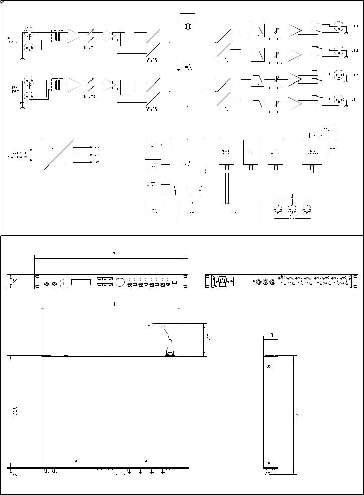
10.Dimensions And Weight
10.1 |
Dimensions W x H x D |
19" (483 mm) x 1 HU (43,6 mm) x 374 mm |
10.2 |
Installation Depth Without Connectors |
356 mm |
10.3 |
Installation Depth Incl. Connectors |
approx. 430 mm |
10.4 |
Weight |
5 kg |
10.5 |
Weight with 2x NRS 90244 |
5.2 kg |
11.Standards
11.1 |
Safety Class according to EN 60065 |
safety class I, grounded |
11.2 |
Electrical Safety In Accordance To |
EN 60065 (VDE 0860) or IEC 65 |
|
|
UL, CSA |
11.3 |
EMC In Accordance To |
EN 50081-1, EN 50082-1, EN 55022-B |
12.Retrofiting-Kits
12.1 |
NRS 90244 |
input transformer for 1 input |
Order No. 112 757 |
12.2 |
NRS 90246 |
contact closure interface |
Order No. 112 766 |
12.3 |
NRS 90247 |
RS-485 interface |
Order No. 112 767 |
13.General
13.1The following equipment had been used for measuring:
Digital Multi-Meter PM 2517 X |
Philips |
System One |
Audio Precision |
Oscilloscope 2465 A |
Tektronix |
Regulation de-coupling transformer RT 5A |
Grundig |
Watt-Meter (electronical) |
Dynacord |
2
13.2Comments about measurements
-Unless differently stated, all measurement has been performed at 20°C ± 2°C
-All stated levels ± 1 dB
[1]all controls set to their clockwise margin
[2]Service program 'SINE WAVE OUT' , set a level of 0 dB,
Output voltage = approx. 8,9 V = +21 dBu = 0 dBr,
+ and - outputs summed via 10 kΩ / 0,1 % resistors, with VR301 ... VR601 adjusted for minimum levels U ≤ 87 mV = -19 dBu = -40 dBr
[3]measured with service program 'ORIGINAL THRU' , level 0 dB, all controls set to their clockwise margin, input level +10 dBu
[4]measured with service program 'ORIGINAL THRU' , level 0 dB,
input controls at center position, output controls set to their clockwise margin
[5]measured with service program 'ORIGINAL THRU' , level 0 dB, all controls set to their clockwise margin,
measurement via bandpass filter 22 Hz ... 22 kHz, weighting filter set to 20 kHz Lo-Pass, Q-Peak, input terminated with 600 Ω
[6]measured with service program 'ORIGINAL THRU' , level 0 dB, all controls set to their clockwise margin,
measurement via bandpass filter 22 Hz ... 22 kHz, weighting filter set to CCIR 468-3, Q-Peak, input terminated with 600 Ω
[7]measured with service program 'ORIGINAL THRU' , level 0 dB, all controls set to their clockwise margin,
measurement via bandpass filter 22 Hz ... 22 kHz, weighting filter set to 'A-weighting', RMS, input terminated with 600 Ω
|
|
|
F r e q u e n c y r e s p o n s e |
|
|
|
|
04/09/99 12:28:14 |
||
|
+ 1 |
|
|
|
|
|
|
|
|
|
|
+0.5 |
|
|
|
|
|
|
|
|
|
|
-0 |
|
|
|
|
|
|
|
|
|
|
-0.5 |
|
|
|
|
|
|
|
|
|
d |
|
|
|
|
|
|
|
|
|
|
B |
-1 |
|
|
|
|
|
|
|
|
|
r |
|
|
|
|
|
|
|
|
|
|
|
-1.5 |
|
|
|
|
|
|
|
|
|
|
-2 |
|
|
|
|
|
|
|
|
|
|
-2.5 |
|
|
|
|
|
|
|
|
|
|
-3 |
|
|
|
|
|
|
|
|
|
|
20 |
50 |
100 |
200 |
500 |
1k |
2k |
5k |
10k |
20k |
|
|
|
|
|
|
H z |
|
|
|
|
Figure 1 Frequency Response [dBr] [3]
3

|
|
|
T H D + N v s L e v e l |
|
|
|
|
|
04/19/99 17:01:22 |
||||
1 |
|
|
|
|
|
|
|
|
|
|
|
|
|
0.5 |
|
|
|
|
|
|
|
|
|
|
|
|
|
0.2 |
|
|
|
|
|
|
|
|
|
|
|
|
|
0.1 |
|
|
|
|
|
|
|
|
|
|
|
|
|
0.05 |
|
|
|
|
|
|
|
|
|
|
|
|
|
% |
|
|
|
|
|
|
|
|
|
|
|
|
|
0.02 |
|
|
|
|
|
|
|
|
|
|
|
|
|
0.01 |
|
|
|
|
|
|
|
|
|
|
|
|
|
0.005 |
|
|
|
|
|
|
|
|
|
|
|
|
|
0.002 |
|
|
|
|
|
|
|
|
|
|
|
|
|
-40 |
-35 |
-30 |
-25 |
-20 |
-15 |
-10 |
-5 |
+ 0 |
+ 5 |
+ 1 0 |
+ 1 5 |
+ 2 0 |
+ 2 5 |
|
|
|
|
|
|
d B u |
|
|
|
|
|
|
|
Figure 2 |
THD+N [%] as a function of the input level [dBu] |
[4] , |
f = 1 kHz |
|
|
||||||||
|
|
|
THD+N vs Frequency |
|
|
|
|
04/20/99 08:53:11 |
|||||
1 |
|
|
|
|
|
|
|
|
|
|
|
|
|
0.5 |
|
|
|
|
|
|
|
|
|
|
|
|
|
0.2 |
|
|
|
|
|
|
|
|
|
|
|
|
|
0.1 |
|
|
|
|
|
|
|
|
|
|
|
|
|
0.05 |
|
|
|
|
|
|
|
|
|
|
|
|
|
% |
|
|
|
|
|
|
|
|
|
|
|
|
|
0.02 |
|
|
|
|
|
|
|
|
|
|
|
|
|
0.01 |
|
|
|
|
|
|
|
|
|
|
|
|
|
0.005 |
|
|
|
|
|
|
|
|
|
|
|
|
|
0.002 |
|
|
|
|
|
|
|
|
|
|
|
|
|
20 |
|
50 |
100 |
|
200 |
500 |
|
1k |
2k |
|
5k |
10k |
20k |
|
|
|
|
|
|
Hz |
|
|
|
|
|
|
|
Figure 3 |
THD+N [%] as a function of the frequency [Hz] [4] , input level = +10 dBu |
|
|
THD+N vs Frequency |
|
|
|
|
04/20/99 11:46:46 |
||
1 |
|
|
|
|
|
|
|
|
|
0.5 |
|
|
|
|
|
|
|
|
|
0.2 |
|
|
|
|
|
|
|
|
|
0.1 |
|
|
|
|
|
|
|
|
|
0.05 |
|
|
|
|
|
|
|
|
|
% |
|
|
|
|
|
|
|
|
|
0.02 |
|
|
|
|
|
|
|
|
|
0.01 |
|
|
|
|
|
|
|
|
|
0.005 |
|
|
|
|
|
|
|
|
|
0.002 |
|
|
|
|
|
|
|
|
|
20 |
50 |
100 |
200 |
500 |
1k |
2k |
5k |
10k |
20k |
|
|
|
|
|
Hz |
|
|
|
|
Figure 4 |
THD+N [%] as a function of the frequency [Hz] [4] , input level = +10 dBu |
|
with input transformer (NRS 90244) installed |
4
14.Specifications
Mains voltage
Power consumption
Safety class
Inputs available
Input voltage (nominal) Max. input voltage Input impedance
Common mode rejection AD-conversion
Outputs
Output voltage (nominal) Max. output voltage Output impedance
Min. load impedance DA-conversion
Frequency response S/N ratio
Distortion without transformer Distortion with transformer
Frequency crossovers
Butterworth, Bessel,
Filters
Compressor / limiter
Delay
Data format Sampling rate
MIDI IN / OUT / THRU Display
Dimensions
Weight
Locking function
Accessories / Options
90 - 250 V AC / 50 - 60 Hz 20 watts
I
2 x XLR IN, electronically balanced, transformer optional
2 x XLR OUT (Direct Out)
1.55 V / + 6 dBu
24.5 V / + 30 dBu
20 kohms > 40 dB
24-bit, Sigma-Delta, 128 times oversampling, linear phase
4 x XLR OUT, electronically balanced
1.55 V / + 6 dBu
8.7 V / + 21 dBu < 100 ohms 600 ohms
24-bit, Sigma-Delta, 128 times oversampling
20 Hz - 20 kHz (- 0.5 dB)
115 dB (typical)
<0.01 %
<0.05 %
6, 12, 18, 24 dB/oct. slope; Linkwitz-Riley
26 parametric equalizers
Low-Shelving equalizer, LPN (Lowpass-Notch) switchable
Hi-Shelving equalizer, 6 / 12 dB slope switchable, Lo-Cut filter (B-6 alignment switchable),
Hi-Cut filter, All-Pass filter
4 digital compressors / limiters
3 master delays (2 ms - 900 ms)
4 channel delays (0 ms - 900 ms) delay-increment 21 µsec.
24-bit linear AD / DA conversion, 48-bit processing 48 kHz
Data Dump, Master / Slave operation/ Remote Control 122 x 32 Dots, graphic LC-Display with LED-background lighting
483 x 43.6 x 374 (W x H x D in mm), 19", 1 HU 5 kg / 11 lbs
protection against inadvertent operation via function-lock
PA 1 plexiglas cover 1 HU
NRS 90244 Input transformer
NRS 90247 RS-485 interface
NRS 90246 Contact Closure interface
5
15.Service Programs
The Dx 38 provides several onboard service programs that allow testing internal function blocks. The service mode is entered by simultaneously pressing the ' EDIT ' and ' > ' keys while the unit is powered on.
The display shows briefly: SERVICE MODE
Selecting the service programs in sequence is possible by using the SELECT keys or via the rotary encoder. Pressing the ' RECALL ' key launches the previously selected program or, while a service program is running, to cancel the test.
Switching the device off or by use of the < QUIT > command, the service mode is ceased.
Available Service Programs:
∙µP-ROM TEST
∙µP-RAM TEST
∙EEPROM TEST
∙KEY TEST
∙ENCODER TEST
∙LED TEST
∙DISPLAY TEST
∙RS232 TEST
∙RS485 TEST
∙CONTACT P TEST
∙MIDI TEST
∙DSP-RAM TEST
∙HW-CONN TEST
∙ORIGINAL THRU
∙SINE WAVE OUT
∙PINK NOISE
∙WHITE NOISE
∙A/D GAIN CALIB
∙A/D GAIN RNG 1
∙A/D GAIN RNG 2
∙INITIALIZE MEM
∙FLASH PROGRAM
∙STATISTICS
∙QUIT
µP-ROM TEST
The Flash-ROM (IC102 on the 80449 Digital Board) gets tested by calculating the checksum of the memory contents. If no error has been detected, the display shows ' OK '. If a faulty condition has been detected, the calculated checksum appears on the display.
µP-RAM TEST
The µP-RAM (IC103 on the 80449 Digital Board) is tested. If no error has been detected, the display shows ' OK '. If a faulty condition has been detected, the corresponding address or respectively the erroneously read data appear on the display.
6
 Loading...