

Page 1
SERVICE MANUAL
Dx 38
24 BIT DIGITAL SOUND SYSTEM PROCESSOR
Page 2

WARRANTY (Limited)
Electro-Voice products are guaranteed against malfunction due to defects in materials or workmanship for a specified
period, as noted in the individual product-line statement(s) below, or in the individual product data sheet or owner’s
manual, beginning with the date of original purchase. If such malfunction occurs during the specified period, the
product will be repaired or replaced (at our option) without charge. The product will be returned to the customer
prepaid.
Exclusions and Limitations: The Limited Warranty does not apply to: (a) exterior finish or appearance; (b) certain
specific items described in the individual product-line statement(s) below, or in the individual product data sheet or
owner’s manual; (c) Malfunction resulting from use or operation of the product other than as specified in the product
data sheet or owner’s manual; (d): malfunction resulting from misuse or abuse of the product; or (e): malfunction
occurring at any time after repairs have been made to the product by anyone other than Electro-Voice or any of its
authorized service representatives.
Obtaining Warranty Service: To obtain warranty service, a customer must deliver the product, prepaid, to
Electro-Voice or any of its authorized service representatives together with proof of purchase of the product in the
form of a bill of sale or receipted invoice. A list of authorized service representatives is available from Electro-Voice
at 600 Cecil Street, Buchanan, MI 49107 (616-695-6831) and/or Electro-Voice West at 9130 Glenoaks Boulevard,
Sun Valley, CA 91532 (213-875-1900).
Incidental and Consequential Damages Excluded: Product repair or replacement and return to the customer are
the only remedies provided to the customer. Electro-Voice shall not be liable for any incidental or consequential
damages including, without limitation, injury to persons or property or loss of use. Some states do not allow the
exclusion or limitation of incidental or consequential damages so the above limitation or exclusion may not apply to
you. Other Rights : This warranty gives you specific legal rights, and you may have other rights which vary from state
to state.
Electro-Voice Electronics are guaranteed against malfunction due to defects in materials or workmanship for a
period of three (3) years from the date of original purchase. Additional details are included in the Uniform Limited
Warranty Statement.
Specifications subject to change without notice.
600 Cecil Street, Buchanan, Michigan 49107, Phone 616/695-6831, Fax: 616/695-1304
TELEX/EVI Audio Canada, 705 Progress Ave. Unit 46 Toronto, Onatario, M1H 2x1, Canada , Phone: 800/881-1685, Fax: 877/522-2242
TELEX Communications A.G., Keltenstrasse 11, CH-2563 IPSACH, Switzerland, Phone: 011-41/32-51-6833, Fax: 011-41/32-51-1221
EVI Audio Deutschland GmbH, Hirschberger Ring 45, D-94315, Straubing, Germany, Phone: 011-49/9421-7060, Fax: 011-49/9421-706265
EVI Audio France S.A., Parc de Courcerin-Allee Lech Walesa, Lognes, f-77185 Marne La Vallee, France, Phone: 011-33/1-6480-0090, Fax: 011-33/1-6006-5103
EVI Audio Japan Ltd., 2-5-60 Izumi, Suginami-ku, Tokyo, Japan 168, Phone: 011-81/3-3325-7900, Fax: 011-81/3-3325-7789
EVI Audio (Aust.) Pty., Unit 24, Block C, Slough Business Park, Slough Ave., Silverwater, N.S.W 2141, Australia, Phone 011-61/2-648-3455,
Fax: 011-61/2-648-5585
EVI Audio (Hong Kong) Limited, Unit E & F, 21 /F., Luk Hop Industrial Bldg., 8 Luk Hop St., San Po Kong, Kowloon, Hong Kong, Phone: 011-852/351-3628,
Fax: 011 -852/351-3329
Page 3

Table of Contents
- Safety and Service Instructions
-
- Warranty
-
- Architects and engineers specifications
-
- Measuring data
-
- Bill of materials
-
- Service notes / infos / instructions
-
- Spare parts plan
-
- Circuit diagrams
Electro-Voice
600 Cecil Street,
Buchanan,
Michigan 49107
Phone 616/695-6831
Fax 616/695-1304
e-mail fspain@qtm.net
Page 4
IMPORTANT SAFETY INSTRUCTIONS
The lightning flash with arrowhead symbol, within an equilateral triangle is intended to alert the user to the presence
of uninsulated “dangerous voltage” within the product’s
enclosure that may be of sufficient magnitude to constitute
a risk of electric shock to persons.
The exclamation point within an equilateral triangle is
intended to alert the user to the presence of important
operating and maintance (servicing) instructions in the
literature accompanying the appliance.
1. Read these instructions.
2. Keep these instructions.
3. Heed all warnings.
4. Follow all instructions.
5. Do not use this apparatus near water.
6. Clean only with a damp cloth.
7. Do not block any of the ventilation openings.
Install in accordance with the manufactures instructions.
8. Do not install near any heat sources such as radiators, heat registers, stoves, or other apparatus that produce heat.
9. Only use attachments/accessories specified by the manufacturer.
10. Refer all servicing to qualified service personnel. Servicing is required when the apparatus has been
damaged in any way, such as power-supply cord or plug is damaged, liquid has been spilled or objects have fallen
into the apparatus, the apparatus has been exposed to rain or moisture, does not operate normally, or has
been dropped.
For US and CANADA only:
Do not defeat the safety purpose of the grounding-type plug. A grounding type plug has two blades and a third grounding prong.
The wide blade or the third prong are provided for your safety. When the provided plug does not fit into your outlet, consult an
electrican for replacement of the absolete outlet.
IMPORTANT SERVICE INSTRUCTIONS
CAUTION: These servicing instructions are for use by qualified personnel only. To reduce the
risk of electric shock, do not perform any servicing other than that contained in the
Operating Instructions unless you are qualified to do so. Refer all servicing to
qualified service personnel.
1. Security regulations as stated in the EN 60065 (VDE 0860 / IEC 65) and the CSA E65 - 94 have to be obeyed when
servicing the appliance.
2. Use of a mains separator transformer is mandatory during maintenance while the appliance is opened, needs to be
operated and is connected to the mains
3. Switch off the power before retrofitting any extensions, changing the mains voltage or the output voltage.
4. The minimum distance between parts carrying mains voltage and any accessible metal piece (metal enclosure),
respectively between the mains poles has to be 3 mm and needs to be minded at all times.
The minimum distance between parts carrying mains voltage and any switches or breakers that are not connected
to the mains (secondary parts) has to be 6 mm and needs to be minded at all times.
5. Replacing special components that are marked in the circuit diagram using the security symbol (Note) is only permissible
when using original parts.
6. Altering the circuitry without prior consent or advice is not legitimate.
7. Any work security regulations that are applicable at the location where the appliance is being serviced have to be strictly
obeyed. This applies also to any regulations about the work place itself.
8. All instructions concerning the handling of MOS - circuits have to be observed.
Note:
SAFETY COMPONENT (HAS TO BE REPLACED WITH ORIGINAL PART ONLY)
1-2
Page 5

BESCHREIBUNG
Mit 48 Bit Filteralgorithmen, 24 Bit AD/DA Wandlern und einem Dynamikbereich von 115 dB setzt der Dx 38 neue Maßstäbe für digitale
Lautsprecher Kontroller und Prozessoren. Der Dx 38 ist ein universell
einsetzbarer Digitaler Sound System Processor mit 2 Eingängen und
4 Ausgängen, sowie zusätzlich einer internen Summe der Eingänge 1
und 2. Die Ausgänge können in einer Matrix auf einen beliebigen
Eingang oder die Eingangssumme geroutet werden. Es können Stereo bzw. Dual 2-Weg-Systeme oder 3-Weg+Direct und 4-Weg Systeme, jeweils auch mit Mono Sub-Kanal, aber auch Fullrange Systeme
konfiguriert werden.
In allen Betriebsarten stehen Hoch- und Tiefpaß-Filter für die Frequenzweichen-Funktionen zur Verfügung. Die Auswahl umfaßt LinkwitzRiley, Butterworth und Bessel Filter mit wählbaren Flankensteilheiten
von 6, 12, 18 oder 24 dB/Okt. Eine große Anzahl weiterer Filter
ermöglicht eine äußerst flexible Frequenzgangskorrektur. In den Eingängen finden Sie jeweils einen 5-Band Equalizer, dessen einzelne
Filtersektionen beliebig mit High- und Low-Pass, High- und Low-Shelving oder parametrischen Peak-Dip-Filtern belegt werden können. In
den Ausgängen sind neben den Frequenzweichen-Filtern jeweils 4
weitere Filter enthalten, die ebenfalls als High- und Low-Pass Filter,
High- oder Low-Shelving-Filter, parametrische Peak-Dip-Filter, oder
Allpass-Filter programmiert werden können. Weitere Filtermöglichkeiten sind z. B. Hochpässe 2. Ordnung zur Realisierung von B-6 Alignments, oder spezielle LPN-Filter (Lowpass Notch / Tiefpaß-Sperrfilter)
zur Korrektur des Frequenz- und Phasengangs von Baßreflexboxen.
Zusätzlich ist jeder Kanal mit einem Delay, einem Polaritätswahlschalter, einem programmierbaren Pegelsteller und einem digitalen Kompressor / Limiter ausgestattet. In den Eingängen befinden sich
außerdem noch die Master-Delays.
Der Anwender hat die Wahl zwischen zwei Bedien-Modi: Im einfachsten Fall (No Edit Mode) brauchen nur die verwendeten Lautsprecherkombinationen aus der Liste der Factory Preset Programme ausgewählt werden. Das Gerät ist danach optimal auf die Audioanlage
eingestellt und sofort betriebsbereit. Im Full Edit Mode hingegen
besteht Zugriff auf sämtliche Parameter, so daß beliebige Einstellungen programmiert und gespeichert werden können. Es stehen insgesamt 80 Programmplätze - 50 für die Factory Presets, und weitere 30
für frei programmierbare User-Programme - zur Verfügung.
Die AD/DA-Wandlung im Dx 38 erfolgt mit linearen 24 Bit Wandlern,
wobei es sich in der AD-Sektion um gainranging Sigma-Delta-Wandler
mit 128-fachem Oversampling handelt. Im DA-Bereich wird mit SigmaDelta Wandlern mit 128-fachem Oversampling gearbeitet. Die Signalverarbeitung erfolgt auf zwei 24 Bit Motorola Signalprozessoren.
Technische Informationen
Architects and engineers
specifications
Dx 38
24 BIT DIGITAL SOUND
SYSTEM PROCESSOR
Weitere Merkmale sind:
- FLASH Speicher für Software und Preset Updates über
serielle Schnittstellen
- PC Bedien- und Konfigurationssoftware unter Windows 95 /
Windows 98
- MIDI-Schnittstelle standardäßig
- RS-232, RS-485 Schnittstellen oder Umschaltkontakte optional
- Grafik-Display mit 122 x 32 Dots, hintergrundbeleuchtet
- Ein- und Ausgänge elektronisch symmetrisch in XLR
- Trafosymmetrierung für die Eingänge optional
- Input / Output Pegelsteller, Output Mute Schalter, KanalFunktionsanzeigen SUB, LO, MID, HI
- Input / Output Aussteueranzeigen, Kompressor- und Clip-LED’s
DESCRIPTION
Providing 48-bit filter algorithms, 24-bit AD/DA conversion and a
dynamic range of 115 dB, the Dx 38 sets new standards for digital
loudspeaker controllers and processors. The Dx 38 is an universal
Digital Sound System Processor that provides 2 inputs and 4 outputs;
plus internal summing of the inputs 1 and 2. Via matrix it is possible to
assign the outputs to any input or to the sum of the inputs. It is further
possible to establish the following configurations: Stereo or Dual
2-Way systems, 3-Way + Direct and 4-Way systems, each with Mono
Sub-channel, but also full range systems.
High and low-pass filters are provided for the frequency crossover
functions in all operation modes. The selection includes Linkwitz-Riley, Butterworth and Bessel type filters with switchable slopes between
6, 12, 18 and 24 dB/oct. A huge number of additional filters offers
extremely flexible correction of the frequency response. Each input
incorporates a 5-band equalizer, allowing to assign high and low-pass,
high and low-shelving or parametric peak-dip filters to its individual
filter sections. Next to the frequency crossover filters, four additional
filters are employed in each output channel, which also can be set to
work as high or low-pass, high or low-shelving filters, parametric
peak-dip filters, or all-pass filters. Additional filtering is provided
through 2. order high-passes for the realization of B-6 alignment, or
special LPN-filters (Low-Pass Notch filters) for correcting the frequency and phase responses of optimally vented woofer cabinets. Each
channel additionally provides a delay, a polarity switch, a programmable level control and a digital compressor / limiter while the master
delays are located in the input channels.
The user can choose between two operation modes: the “No Edit
Mode” allows to simply select the required combination of loudspeaker
systems from the factory preset program list. Afterwards, the appliance
is optimally matched to the sound system and can be operated
instantly. The “Full Edit Mode” on the other hand offers access to all
parameters, allowing to freely program and store basically any setting.
A total number of 80 memory addresses - 50 preset and 30 freely
assignable user-programs - are available.
Page 6

Within the Dx 38, AD/DA conversion is taken care of by linear 24-bit
90 - 250 V AC / 50 - 60 Hz
converters; where the AD-section employs 128 times oversampling,
gain-ranging Sigma-Delta converters. The DA-section offers 128 times
oversampling Sigma-Delta converters. The overall signal processing
is performed by two 24-bit Motorola signal processors.
Additional features are:
- FLASH memory for software and preset updates via serial
interfaces
- PC-based operation and configuration software running under
Windows ‘95 / Windows ‘98
- Standard MIDI-interface
- RS-232, RS-485 interfaces or switching contacts optionally
available
- Back-lit graphic-display with 122 x 32 dots
- Inputs and outputs are electronically balanced, XLR-type
connectors
- Input transformer-balancing is optionally available
- Input / Output level controls, Output-Mute switch, channel
function indicators SUB, LO, MID, HI
- Input / Output meter instruments, compressor and clipping LEDs
DESCRIPTION
Avec ses algorithmes de filtrage travaillant en 48 bits, ses convertisseurs A/N et N/A 24 bits et sa gamme dynamique de 115 dB, le Dx
38 définit de nouveaux standards dans le domaine des contrôleurs et
processeurs numériques de haut-parleurs. Le Dx 38 est un processeur
numérique de diffusion universel ; il est pourvu de 2 entrées et 4 sorties,
un circuit interne permettant de sommer les entrées 1 et 2. Une matrice
permet d’assigner les sous-bandes du signal d’entrée stéréo (ou
sommé en mono) à n’importe quelle(s) sortie(s). D’origine, les configurations suivantes sont disponibles : systèmes stéréo 2 voies, mono
2 voies, 3 voies + sortie directe, ou système mono 4 voies, tous offrant
éventuellement une sortie mono pour canal Subwoofer et une sortie
“large bande”.
Dans tous les modes de fonctionnement, ce sont des filtres passe-haut
et passe-bas qui se chargent de répartir le spectre audio en plusieurs
bandes de fréquences (crossover). Ces filtres peuvent être de type
Linkwitz-Riley, Butterworth ou Bessel, avec des pentes commutables
entre 6, 12, 18 et 24 dB/octave. De nombreux autres correcteurs
permettent de modeler la courbe de réponse à votre guise : chaque
entrée possède par ailleurs cinq correcteurs, pouvant être un filtre
passe-haut ou passe-bas, un correcteur d’aigus ou de graves de type
Shelve (en plateau), ou un filtre paramétrique. Une fois le signal
d’origine réparti en plusieurs bandes, quatre autres correcteurs peuvent prendre place sur chaque canal de sortie : eux aussi peuvent
travailler en modes passe-haut ou passe-bas, correcteur d’aigus ou
de graves de type Shelve (en plateau), filtre paramétrique, voire filtre
passe-tout. Des fonctions de filtrage supplémentaires sont encore
prévues, sous la forme de filtres passe-haut du second ordre permettant la réalisation d’alignements de type B-6, ou des filtres spéciaux
de type LPN (pour Low-Pass Notch, filtres passe-bas de type Notch)
permettant de corriger la réponse en fréquence et en phase d’enceintes de graves travaillant en bass-reflex.
Chaque canal offre en plus un délai, un inverseur de phase, un réglage
de niveau programmable et un compresseur/limiteur numérique, les
délais principaux se trouvant au niveau des canaux d’entrée.
Deux modes de fonctionnement sont à la disposition de l’utilisateur :
le mode “No Edit”, qui ne permet que de sélectionner la combinaison
d’enceintes désirée dans la liste donnée par le Programme Preset
d’usine. Dans ce cas, l’appareil est configuré de façon optimale en
fonction de l’installation, et peut être exploité instantanément. Enfin, le
mode “Full Edit”, lui, permet d’accéder à tous les paramètres, ce qui
permet de programmer en toute liberté et de mémoriser ses Programmes. L’appareil compte 80 emplacements mémoire - 50 pour les
Programmes Presets d’usine et 30 pour les Programmes utilisateur.
À l’intérieur du Dx 38, les conversions A/N et N/A s’effectuent en 24
bits linéaires (Delta-Sigma, suréchantillonnage 128 fois), et les traitements du signal sont calculés par deux DSP Motorola 24 bits.
Parmi les autres caractéristiques :
- Mémoire FLASH pour le logiciel d’exploitation et les Presets,
ce qui permet la mise à jour via interface série.
- Logiciel de configuration et de commande pour PC, tournant
sous Windows 95/98.
- Interface MIDI Standard.
- En option, commande via interfaces RS-232, RS-485 ou
commutation par contacts.
- Affichage graphique rétro-éclairé, 122 x 32 points.
- Entrées et sorties sur XLR, symétrie électronique.
- En option, symétrisation par transformateur d’entrée.
- Potentiomètres de réglage des niveaux d’entrée et de sortie,
commutateur de coupure des sorties (Mute) indicateurs SUB,
LO, MID, HI par canal.
- Visualisation par VU-mètres des entrées/sorties, du compresseur,
LED d’écrêtage.
TECHNICAL SPECIFICATIONS
Mains voltage
Power consumption 20 watts
Safety class I
Inputs 2 x XLR IN, electronically balanced,
transformer optional available
2 x XLR OUT (Direct Out)
Input voltage (nominal) 1.55 V / + 6 dBu
Max. input voltage 24.5 V / + 30 dBu
Input impedance 20 kohms
Common mode rejection > 40 dB
AD-conversion 24-bit, Sigma-Delta, 128 times
oversampling, linear phase
Outputs 4 x XLR OUT, electronically balanced
Output voltage (nominal) 1.55 V / + 6 dBu
Max. output voltage 8.7 V / + 21 dBu
Output impedance < 100 ohms
Min. load impedance 600 ohms
DA-conversion 24-bit, Sigma-Delta, 128 times
oversampling
Frequency response 20 Hz - 20 kHz (- 0.5 dB)
S/N ratio 115 dB (typical)
Distortion without transformer < 0.01 %
Distortion with transformer < 0.05 %
Frequency crossovers 6, 12, 18, 24 dB/oct. slope;
Butterworth, Bessel, Linkwitz-Riley
Filters 26 parametric equalizers
Low-Shelving equalizer,
LPN (Lowpass-Notch) switchable
Hi-Shelving equalizer, 6 / 12 dB slope
switchable, Lo-Cut filter (B-6 alignment
switchable), Hi-Cut filter, All-Pass filter
Compressor / limiter 4 digital compressors / limiters
Delay 3 master delays (2 ms - 900 ms)
4 channel delays (0 ms - 900 ms)
delay-increment 21 µsec.
Data format 24-bit linear AD / DA conversion,
48-bit processing
Sampling rate 48 kHz
MIDI IN / OUT / THRU Data Dump, Master / Slave operation,
Remote Control
Display 122 x 32 Dots, graphic LC-Display with
LED-background lighting
Dimensions 483 x 43.6 x 374 (WxHxD in mm), 19", 1 HU
Weight 5 kg / 11 lbs
Locking function Protection against inadvertent operation
via function-lock
Accessories PA 1 plexiglas cover 1 HU
Options NRS 90244 Input transformer
NRS 90247 RS-485 interface
NRS 90246 Contact Closure interface
Page 7
Page 8

Measuring data Dx 38 – complete device
1. Power Supply
1.1 Operation Voltage U Mains 90 - 250 V AC, 50 - 60 Hz
1.2 Operation Current at U Mains = 110 V AC 200 mA
at U Mains = 230 V AC 130 mA
1.3 Power Consumption 14 W
1.4 Internal Operation Voltage +5 V ± 0,1 V
+18 V ± 1 V
-18 V ± 1 V
1.5 Internal Operation Currents +5 V max. 460 mA
+18 V max. 400 mA
-18 V max. 250 mA
1.6 Power Supply Switching Frequency 192 kHz
2. Inputs
2 x XLR IN, electronically balanced, 2 x XLR Direct Out,
Input transformers (NRS 90244) are optionally available
2.1 Input Impedance electronically balanced 20 kΩ
2.2 Input Voltage [1] 4,5 V = +15 dBu
Max. Input Voltage 24,5 V = +30 dBu
2.3 Common Mode Rejection CMRR ≥ 40 dB
3. Outputs
4 x XLR OUT, electronically balanced
3.1 Output Impedance < 100 Ω
3.2 Min. Load Impedance 600 Ω
3.3 Max. Output Voltage [1] 8,7 V = +21 dBu
3.4 Output Symmetry [1] [2] ≥ -40 dB
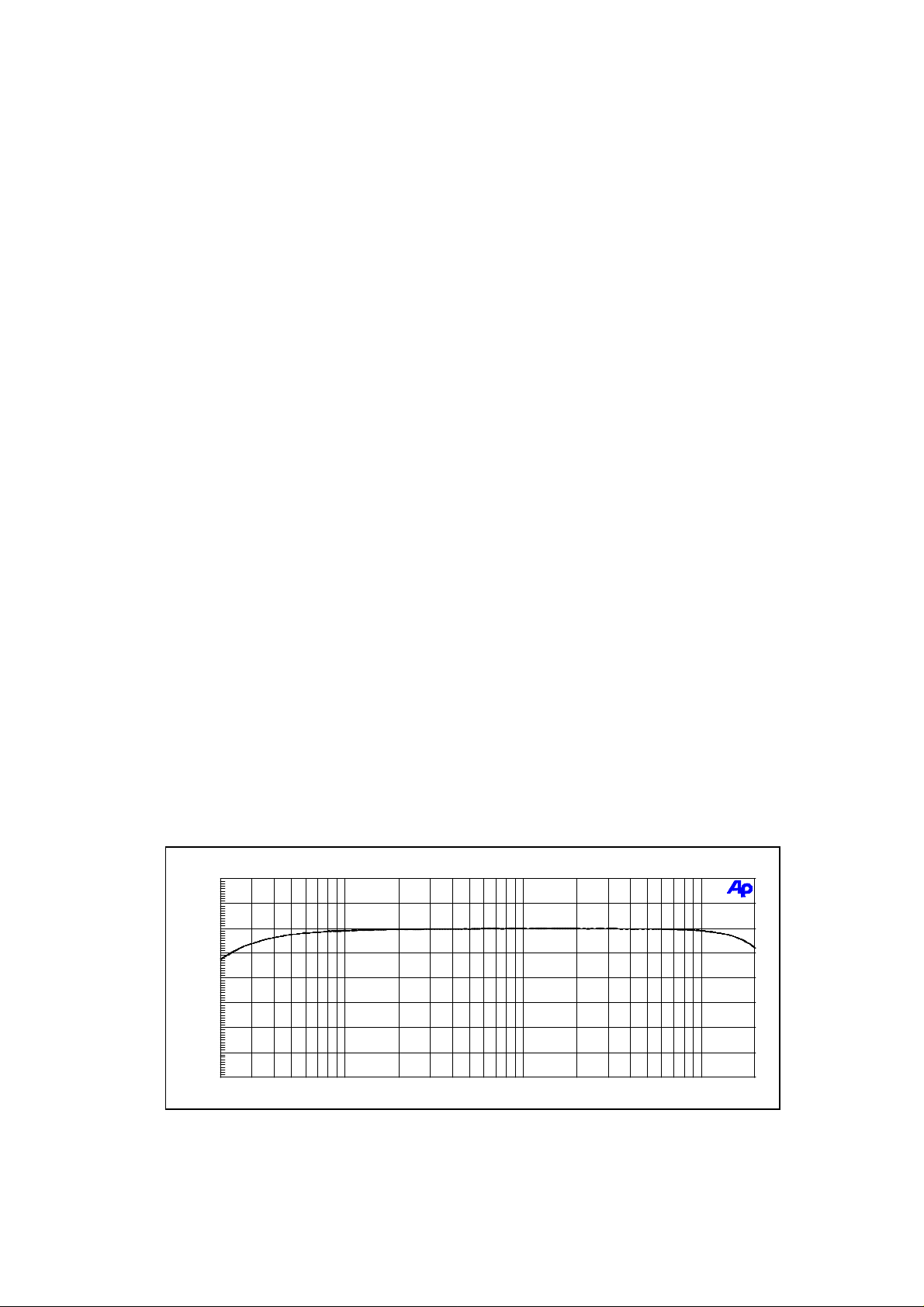
4. Frequency Response
4.1 Frequency Response [3] fig. 1 30 Hz ... 20 kHz - 0.5 dB
5. Crosstalk
5.1 Crosstalk Attenuation [3] > 80 dB
1
Page 9

6. Distortion
6.1 THD+N [4] fig. 2 , fig. 3 20 Hz ... 20 kHz < 0.01 % @ +10 dBu
7. Interference Voltages
7.1 Wide Band Noise Voltage [5] ≤ 50 µV = -84 dBu
7.2 Noise Voltage (CCIR 468-3) [6] ≤ 140 µV = -75 dBu
7.3 Noise Voltage (A-weighted) [7] ≤ 18 µV = -93 dBu
8. Retrofitting Input Transformers
Retrofitting input transformers NRS 90244 results in the change of the following values:
8.1 THD+N [4] figure 4 70 Hz ... 20 kHz < 0.01 % @ +10 dBu
THD+N [4] figure 4 20 Hz ... 20 kHz < 0.05 % @ +10 dBu
9. Other Specifications
9.1 Operation Temperature Range +5 ... +40 °C
9.2 Temperature Range During Storage And Shipment -40 ... +70 °C
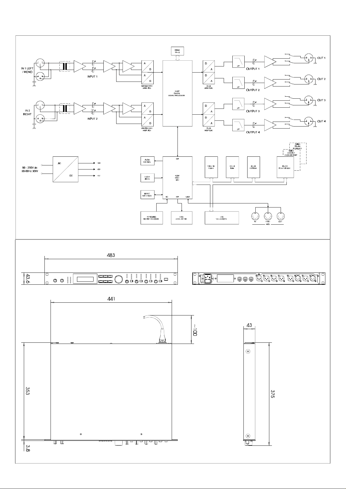
10. Dimensions And Weight
10.1 Dimensions W x H x D 19" (483 mm) x 1 HU (43,6 mm) x 374 mm
10.2 Installation Depth Without Connectors 356 mm
10.3 Installation Depth Incl. Connectors approx. 430 mm
10.4 Weight 5 kg
10.5 Weight with 2x NRS 90244 5.2 kg
11. Standards
11.1 Safety Class according to EN 60065 safety class I, grounded
11.2 Electrical Safety In Accordance To EN 60065 (VDE 0860) or IEC 65
UL, CSA
11.3 EMC In Accordance To EN 50081-1, EN 50082-1, EN 55022-B
12. Retrofiting-Kits
12.1 NRS 90244 input transformer for 1 input Order No. 112 757
12.2 NRS 90246 contact closure interface Order No. 112 766
12.3 NRS 90247 RS-485 interface Order No. 112 767
13. General
13.1 The following equipment had been used for measuring:
Digital Multi-Meter PM 2517 X Philips
System One Audio Precision
Oscilloscope 2465 A Tektronix
Regulation de-coupling transformer RT 5A Grundig
Watt-Meter (electronical) Dynacord
2
Page 10
13.2 Comments about measurements
04/09/99 12:28:14
Frequency response
- Unless differently stated, all measurement has been performed at 20°C ± 2°C
- All stated levels ± 1 dB
[1] all controls set to their clockwise margin
[2] Service program 'SINE WAVE OUT' , set a level of 0 dB,
Output voltage = approx. 8,9 V = +21 dBu = 0 dBr,
+ and - outputs summed via 10 kΩ / 0,1 % resistors, with VR301 ... VR601
adjusted for minimum levels U ≤ 87 mV = -19 dBu = -40 dBr
[3] measured with service program 'ORIGINAL THRU' , level 0 dB, all controls set to their
clockwise margin, input level +10 dBu
[4] measured with service program 'ORIGINAL THRU' , level 0 dB,
input controls at center position, output controls set to their clockwise margin
[5] measured with service program 'ORIGINAL THRU' , level 0 dB, all controls
set to their clockwise margin,
measurement via bandpass filter 22 Hz ... 22 kHz, weighting filter set to 20 kHz Lo-Pass,
Q-Peak, input terminated with 600 Ω
[6] measured with service program 'ORIGINAL THRU' , level 0 dB, all controls
set to their clockwise margin,
measurement via bandpass filter 22 Hz ... 22 kHz, weighting filter set to CCIR 468-3,
Q-Peak, input terminated with 600 Ω
[7] measured with service program 'ORIGINAL THRU' , level 0 dB, all controls
set to their clockwise margin,
measurement via bandpass filter 22 Hz ... 22 kHz, weighting filter set to 'A-weighting',
RMS, input terminated with 600 Ω
Figure 1 Frequency Response [dBr] [3]
3
Page 11
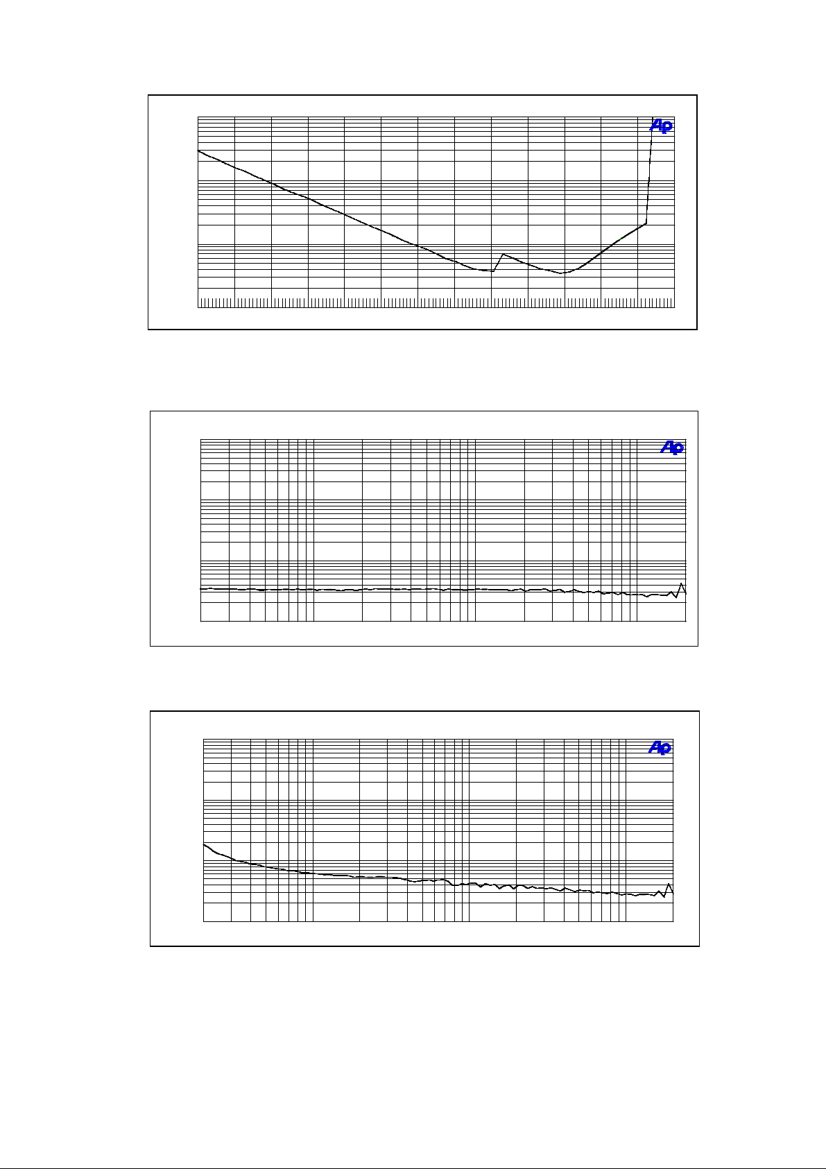
Figure 2 THD+N [%] as a function of the input level [dBu] [4] , f = 1 kHz
04/19/99 17:01:22
THD+N vs Level
04/20/99 08:53:11
THD+N vs Frequency
04/20/99 11:46:46
THD+N vs Frequency
Figure 3 THD+N [%] as a function of the frequency [Hz] [4] , input level = +10 dBu
Figure 4 THD+N [%] as a function of the frequency [Hz] [4] , input level = +10 dBu
with input transformer (NRS 90244) installed
4
Page 12

14. Specifications
Mains voltage 90 - 250 V AC / 50 - 60 Hz
Power consumption 20 watts
Safety class I
Inputs 2 x XLR IN, electronically balanced, transformer optional
available 2 x XLR OUT (Direct Out)
Input voltage (nominal) 1.55 V / + 6 dBu
Max. input voltage 24.5 V / + 30 dBu
Input impedance 20 kohms
Common mode rejection > 40 dB
AD-conversion 24-bit, Sigma-Delta, 128 times oversampling, linear phase
Outputs 4 x XLR OUT, electronically balanced
Output voltage (nominal) 1.55 V / + 6 dBu
Max. output voltage 8.7 V / + 21 dBu
Output impedance < 100 ohms
Min. load impedance 600 ohms
DA-conversion 24-bit, Sigma-Delta, 128 times oversampling
Frequency response 20 Hz - 20 kHz (- 0.5 dB)
S/N ratio 115 dB (typical)
Distortion without transformer < 0.01 %
Distortion with transformer < 0.05 %
Frequency crossovers 6, 12, 18, 24 dB/oct. slope;
Butterworth, Bessel, Linkwitz-Riley
Filters 26 parametric equalizers
Low-Shelving equalizer, LPN (Lowpass-Notch) switchable
Hi-Shelving equalizer, 6 / 12 dB slope switchable,
Lo-Cut filter (B-6 alignment switchable),
Hi-Cut filter, All-Pass filter
Compressor / limiter 4 digital compressors / limiters
Delay 3 master delays (2 ms - 900 ms)
4 channel delays (0 ms - 900 ms)
delay-increment 21 µsec.
Data format 24-bit linear AD / DA conversion, 48-bit processing
Sampling rate 48 kHz
MIDI IN / OUT / THRU Data Dump, Master / Slave operation/ Remote Control
Display 122 x 32 Dots, graphic LC-Display with
LED-background lighting
Dimensions 483 x 43.6 x 374 (W x H x D in mm), 19", 1 HU
Weight 5 kg / 11 lbs
Locking function protection against inadvertent operation via function-lock
Accessories / Options PA 1 plexiglas cover 1 HU
NRS 90244 Input transformer
NRS 90247 RS-485 interface
NRS 90246 Contact Closure interface
5
Page 13

15. Service Programs
The Dx 38 provides several onboard service programs that allow testing internal function blocks.
The service mode is entered by simultaneously pressing the ' EDIT ' and ' > ' keys while the unit is
powered on.
The display shows briefly: SERVICE MODE
Selecting the service programs in sequence is possible by using the SELECT keys or via the rotary
encoder. Pressing the ' RECALL ' key launches the previously selected program or, while a service
program is running, to cancel the test.
Switching the device off or by use of the < QUIT > command, the service mode is ceased.
Available Service Programs:
• µP-ROM TEST
• µP-RAM TEST
• EEPROM TEST
• KEY TEST
• ENCODER TEST
• LED TEST
• DISPLAY TEST
• RS232 TEST
• RS485 TEST
• CONTACT P TEST
• MIDI TEST
• DSP-RAM TEST
• HW-CONN TEST
• ORIGINAL THRU
• SINE WAVE OUT
• PINK NOISE
• WHITE NOISE
• A/D GAIN CALIB
• A/D GAIN RNG 1
• A/D GAIN RNG 2
• INITIALIZE MEM
• FLASH PROGRAM
• STATISTICS
• QUIT
µP-ROM TEST
The Flash-ROM (IC102 on the 80449 Digital Board) gets tested by calculating the checksum of
the memory contents. If no error has been detected, the display shows ' OK '. If a faulty condition
has been detected, the calculated checksum appears on the display.
µP-RAM TEST
The µP-RAM (IC103 on the 80449 Digital Board) is tested. If no error has been detected, the
display shows ' OK '. If a faulty condition has been detected, the corresponding address or
respectively the erroneously read data appear on the display.
6
Page 14

EEPROM TEST
The EEPROM (IC105 on the 80449 Digital Board) is tested. If no error has been detected, the
display shows ' OK '. If a faulty condition has been detected, the corresponding address or
respectively the erroneously read data appear on the display.
KEY TEST
The function of all keys gets tested. The function of the key that gets pressed appears on the
display. Testing is canceled by pressing the rotary encoder.
ENCODER TEST
The function of the rotary encoder gets tested. When turning the wheel, the direction (+/-) and
the amount of impulses is displayed.
LED TEST
All LEDs on the front of the appliance are checked. All LEDs are accessed in sequential order.
Upon ending the test, all LEDs light.
DISPLAY TEST
This program is meant for testing the LC-display and setting its contrast. Using the rotary
encoder lets you adjust the LCD-contrast in a range between -10 to +10.
After pressing any key, a graphic pattern appears on the display, which allows checking whether
all pixels are active.
RS232 TEST
The RS-232 interface gets tested by sending and reading back data. During this test, pins 2 and
3 of the RS-232 connector have to be bridged by using a special bridging-plug.
If no error has been detected, the display shows ' OK '. If a faulty condition has been detected,
the display shows whether the data was corrupted during the internal reading (in the UART, IC1)
or at the external bridging plug.
RS-485 TEST
The optional RS-485 interface gets tested by sending and reading back data.
If no error has been detected, the display shows ' OK '. If a faulty condition has been detected,
the display shows whether the data was corrupted during the internal reading (in the UART, IC1)
or at the external RS-485 driver (IC2).
CONTACT P TEST
The optional contact closure port is tested. Therefore the bit-pattern which is present at pins 1-8
is read and shown on the display. By connecting external contacts to ground potential, the pins
can be pulled to "0". The test is completed with OK when each contact had been closed at least
once.
MIDI TEST
The MIDI interface gets tested. Therefore you have to connect the MIDI IN and MIDI OUT
connectors with a MIDI-cable. If no error has been detected, the display shows ' OK '. Otherwise,
the display shows: FAIL (no receive).
DSP-RAM TEST
Here, the delay memory gets tested. The data and address busses from the DSP to the RAMs
(IC203 and IC204 on the 80449 Digital Board) are tested in sequential order. If no error has been
detected, the display shows ' OK '. If a faulty condition has been detected, the number of the
faulty data or address bus appears on the display.
HW-CONN TEST
This test checks internal status and control lines. Special hardware is necessary to perform this
test. It is not recommended to perform this test with the appliance being a standalone
unit. Instead, always use a testing-adapter.
7
Page 15

ORIGINAL THRU
Within this program, the incoming data is directly send to the outputs, without employing
additional signal processing. Output is carried out in a 2 in 2 configuration, i. e. input 1 is
assigned to the outputs 1 and 2, Input 2 is assigned to 3 and 4.
The rotary encoder lets you control the level in the range between 0 to -99 dB.
SINE WAVE OUT
This program tests the entire output signal path (DSP, D/A converters, output channels). After
starting the program, a 1 kHz sine signal is generated in the DSP, which is output to all 4
channels.
The default level setting is -24 dB. The rotary encoder lets you control the level in the range
between 0 to -99 dB.
PINK NOISE
"Pink noise" is generated in the DSP, which then is output to all 4 channels. The default level
setting is -24 dB. The rotary encoder allows controlling the level in the range between 0 and
-99 dB.
WHITE NOISE
"White noise" is generated in the DSP, which then is output to all 4 channels. The default level
setting is -24 dB. The rotary encoder allows controlling the level in the range between 0 and
-99 dB.
A/D GAIN CALIB
This program serves for calibrating the gain-ranging AD-converters. The difference in the levels
between high and low inputs at the ADC is automatically measured and stored.
For automatic calibration, a sine signal with approx. 0dBu / 1kHz has to be fed to both inputs.
Level differences are measured and displayed. Too high or too low signal levels are also
indicated on the display. CAUTION: The use of this program should be left to the
experienced and well-educated service technician. Inaccurate calibration can result in the
degradation of the dynamic range or even in erroneous functioning of the appliance.
A/D GAIN RNG 1
This program serves for precisely displaying and adjusting the level difference between the gainranging A/D converter's two channels of input 1. The value is indicated in dB and in hex-code. in
the degradation of the dynamic range or even in erroneous functioning of the appliance.
CAUTION: The use of this program should be left to the experienced and well-educated
service technician. Inaccurate calibration can result in the degradation of the dynamic
range or even in erroneous functioning of the appliance.
A/D GAIN RNG 2
This program serves for precisely displaying and adjusting the level difference between the gainranging A/D converter's two channels of input 2. The value is indicated in dB and in hex-code.
CAUTION: The use of this program should be left to the experienced and well-educated
service technician. Inaccurate calibration can result in the degradation of the dynamic
range or even in erroneous functioning of the appliance.
INITIALIZE MEM
This program erases all entries of the user preset memory U01 - U30 and re-sets the unit's
programming to the initial state (as shipped). The initialize function is ended with a software
reset. Upon re-start the appliance is set to the factory program F01.
CAUTION: To prevent the total loss of user-defined data, previously backing-up the
contents of the user preset memory, using the Dx 38 editor software, onto a PC or
notebook computer is strongly recommended.
8
Page 16

ENCODER TYPE
This program allows setting the appliance to the employed type of encoder. Changing the
encoder type is only necessary when older models with serial numbers up to 11228 (Dx 38) are
updated to a new operating system (V1.10 or newer). When shipped, the appliance is always
correctly factory-set, matching the employed encoder type.
STATISTICS
This program provides indication of how often the appliance has been switched on (Power on
count) and its hours of operation (Opr. Time).
QUIT
This command ceases the test mode. The appliance re-starts with the program that was active
before entering test mode.
Testing The µP-System During Power-On
During switching on the unit or performing a hardware reset, the indication of the status-LEDs D101
and D102 (located on the Digital PCB 80449) lets you localize a fault in the processor system.
The following happens in sequential order during a hardware reset of the Dx 38 CPU-system:
1. Hardware Reset → D101 lights D102 lights
2. CPU Start and Initialization
o. k. → D101 dimmed D102 lights
3. Checksum Test Bootload-ROM
fault → System 'hangs'
o. k. → D101 lights D102 dimmed
4. External RAM Test
fault → System 'hangs'
o. k. → D101 dimmed D102 dimmed
5. Checksum Test Application-ROM
fault → bootloader controls LEDs and RS232
D101 blinks with non-irq-task
D102 blinks with irq-task
o. k. → application starts and controls LEDs and RS232
D101 blinks with non-irq-task
D102 blinks with irq-task
9
Page 17

Page 18

IN 1 LEFT
/ MONO
IN 2
RIGHT
90 - 250V ac
50-60Hz 30W
1 2
3
1 2
3
1 2
3
1 2
3
AC
DC
INPUT 1
INPUT 2
+18V
-18V
+5V
A
D
A
D
GAINRANGING
24 BIT ADC
A
D
A
D
GAINRANGING
24 BIT ADC
AUDIO
CONTROL
CLOCK
48 kHz
DRAM
1M x 8
24 BIT
DIGITAL
SIGNAL PROCESSOR
SPI
16 BIT
HOST
CPU
D
D
DUAL
24 BIT DAC
D
D
DUAL
24 BIT DAC
128k x 16
FLASH
12
OUT 1
3
LPF
LPF
OUTPUT 1
12
OUT 2
3
A
A
OUTPUT 2
12
OUT 3
3
LPF
LPF
OUTPUT 3
12
OUT 4
3
A
A
OUTPUT 4
Option:
RS-485
INTERFACE
Option:
CONTACT
CLOSURE PORT
32k x 8
RAM
8k x 8
EEPROM
RS-232
PC INTERFACE
RESET
WATCHDOG
KEYBOARD
ROTARY ENCODER
SPI
LEDs
LEVEL METER
UART
LCD
122 x 32 DOTS
MIDI
OUTTHRUIN
I/O
Page 19

Page 20

Page 21

Page 22

Page 23

Page 24

Page 25

Page 26

Page 27

Page 28

Page 29

Page 30

Stücklisten - Bill of materials
170086
DX 38
Pos. Nr.
Best. Nr.
Zubehör
Accessories
Mechanische Teile
Metal work
Platinen
printed circuit boards
804488
PCBAR#DX 38
pcb assy 80448
Ref. No.
Z 020 345095 FUSS-GUMMI 12.7X 3.5 rubber foot
Z0050 356311 BEDIENUNGSANL. DX 38 owner's manual
Z0052 357771 BEDIENUNGSANL. DX 38 FRA. owner's manual french
Z0055 357755 PRESET LIST DX 38 list of presets
Z0060 300425 KABEL-NETZ 2.0 M 10A power cable Europe
Z0070 357653 * ZUBEHÖR: SOFTWARE DX 38 software dx38
Z0080 356958 KABEL-SCHNITTSTELLE cable interface
Part No. Bezeichnung Description
354617 KABEL-NETZ UL/CSA 15A/125V power cable US
337059 KNOPF-TASTE 12X7 SW 3.3 push button black 12x7
347430 TK 10X6 SW 2,8 push button black 10x6
356454 DK 11 SW/GR/SW A 6FL rotary knob
356272 DK 28 SW 6 rotary knob
356275 KAPPE 28 SW cap for rotary knob
356062 EINLEGEFOLIE DSP 244 mylar for display
356507 STECKER-KALTGERÄTE mains connector male
302581 SICHER T 800 MA 250V fuse 800 mA slow blow
356499 KRT. DSP 244 512X422X102 carton
357500 STYROPOR-EINLAGE DSP 244 carton filler
333375 SCHUTZHÜLLE 500X700X0,05 poly bag
357961 DAT.BLATT/EDS DX 38 eds dx38
356216 FB.DX 38 BED front panel dx38
356466 BLEND.DX38/DSP244 BED panel sub
356218 DEC.DX 38 BED cover chassis
old 357036 NETZTEIL-SCHALT BEARB.AUS power supply switching
new !! *1 357007 NETZTEIL-SCHALT switching power supply
CN101 345489 MESSERLST. 6POL connector male 6-pin
CN301 345489 MESSERLST. 6POL connector male 6-pin
CN501 345489 MESSERLST. 6POL connector male 6-pin
CN701 352198 MESSERLST. 48POL connector male 48-pin
CN702 348676 STIFTLEISTE 3POL MLSS connector male 3-pin
CN703 356589 STIFTLEISTE 26POL connector male 36-pin
C0101 356508 KO-KER 0.10MF 50V 20% cap ceramic 100nF
C0102 356508 KO-KER 0.10MF 50V 20% cap ceramic 100nF
C0103 301530 KO-KER 100.0PF 500V 10% cap ceramic 100pF
C0104 301530 KO-KER 100.0PF 500V 10% cap ceramic 100pF
C0105 301530 KO-KER 100.0PF 500V 10% cap ceramic 100pF
C0106 301530 KO-KER 100.0PF 500V 10% cap ceramic 100pF
C0107 335787 KO-KER 15.0PF 100V 2% cap ceramic 15pF
C0108 343530 KO-EL 47.000MF 50V cap electrolytic 47uF/50V
C0109 343530 KO-EL 47.000MF 50V cap electrolytic 47uF/50V
C0110 340988 KO-FOL 0.470MF 63V 5% cap mylar 470nF
Page 31

Pos. Nr.
Ref. No.
Best. Nr.
C0111 340988 KO-FOL 0.470MF 63V 5% cap mylar 470nF
C0112 301524 KO-KER 47.0PF 500V 10% cap ceramic 47pF
C0113 301524 KO-KER 47.0PF 500V 10% cap ceramic 47pF
C0114 327365 KO-EL 47.000MF 25V BIP cap electr. bip 47uF/25V
C0115 327365 KO-EL 47.000MF 25V BIP cap electr. bip 47uF/25V
C0116 326922 KO-FOL 1000.000PF 100V 5% cap mylar 1nF
C0117 301524 KO-KER 47.0PF 500V 10% cap ceramic 47pF
C0118 301524 KO-KER 47.0PF 500V 10% cap ceramic 47pF
C0119 327365 KO-EL 47.000MF 25V BIP cap electr. bip 47uF/25V
C0120 327365 KO-EL 47.000MF 25V BIP cap electr. bip 47uF/25V
C0121 326922 KO-FOL 1000.000PF 100V 5% cap mylar 1nF
C0122 340522 KO-EL 10.000MF 35V cap electrolytic 10uF/35
C0123 356508 KO-KER 0.10MF 50V 20% cap ceramic 100nF
C0124 340522 KO-EL 10.000MF 35V cap electrolytic 10uF/35
C0125 356508 KO-KER 0.10MF 50V 20% cap ceramic 100nF
C0126 329021 KO-KER 0.10MF 100V 20% cap ceramic 100nF
C0127 329021 KO-KER 0.10MF 100V 20% cap ceramic 100nF
C0128 329021 KO-KER 0.10MF 100V 20% cap ceramic 100nF
C0129 329021 KO-KER 0.10MF 100V 20% cap ceramic 100nF
C0130 329021 KO-KER 0.10MF 100V 20% cap ceramic 100nF
C0131 329021 KO-KER 0.10MF 100V 20% cap ceramic 100nF
C0132 329021 KO-KER 0.10MF 100V 20% cap ceramic 100nF
C0133 301472 KO-EL 10.000MF 63V cap electrolytic 10uF/63V
C0201 356508 KO-KER 0.10MF 50V 20% cap ceramic 100nF
C0202 356508 KO-KER 0.10MF 50V 20% cap ceramic 100nF
C0203 301530 KO-KER 100.0PF 500V 10% cap ceramic 100pF
C0204 301530 KO-KER 100.0PF 500V 10% cap ceramic 100pF
C0205 301530 KO-KER 100.0PF 500V 10% cap ceramic 100pF
C0206 301530 KO-KER 100.0PF 500V 10% cap ceramic 100pF
C0207 335787 KO-KER 15.0PF 100V 2% cap ceramic 15pF
C0208 343530 KO-EL 47.000MF 50V cap electrolytic 47uF/50V
C0209 343530 KO-EL 47.000MF 50V cap electrolytic 47uF/50V
C0210 340988 KO-FOL 0.470MF 63V 5% cap mylar 470nF
C0211 340988 KO-FOL 0.470MF 63V 5% cap mylar 470nF
C0212 301524 KO-KER 47.0PF 500V 10% cap ceramic 47pF
C0213 301524 KO-KER 47.0PF 500V 10% cap ceramic 47pF
C0214 327365 KO-EL 47.000MF 25V BIP cap electr. bip 47uF/25V
C0215 327365 KO-EL 47.000MF 25V BIP cap electr. bip 47uF/25V
C0216 326922 KO-FOL 1000.000PF 100V 5% cap mylar 1nF
C0217 301524 KO-KER 47.0PF 500V 10% cap ceramic 47pF
C0218 301524 KO-KER 47.0PF 500V 10% cap ceramic 47pF
C0219 327365 KO-EL 47.000MF 25V BIP cap electr. bip 47uF/25V
C0220 327365 KO-EL 47.000MF 25V BIP cap electr. bip 47uF/25V
C0221 326922 KO-FOL 1000.000PF 100V 5% cap mylar 1nF
C0222 340522 KO-EL 10.000MF 35V cap electrolytic 10uF/35
C0223 356508 KO-KER 0.10MF 50V 20% cap ceramic 100nF
C0224 340522 KO-EL 10.000MF 35V cap electrolytic 10uF/35
C0225 356508 KO-KER 0.10MF 50V 20% cap ceramic 100nF
C0226 329021 KO-KER 0.10MF 100V 20% cap ceramic 100nF
C0227 329021 KO-KER 0.10MF 100V 20% cap ceramic 100nF
C0228 329021 KO-KER 0.10MF 100V 20% cap ceramic 100nF
C0229 329021 KO-KER 0.10MF 100V 20% cap ceramic 100nF
C0230 329021 KO-KER 0.10MF 100V 20% cap ceramic 100nF
Part No. Bezeichnung Description
Page 32

Pos. Nr.
Ref. No.
Best. Nr.
C0231 329021 KO-KER 0.10MF 100V 20% cap ceramic 100nF
C0301 343532 KO-EL 100.000MF 25V cap electrolytic 100uF/25V
C0302 343532 KO-EL 100.000MF 25V cap electrolytic 100uF/25V
C0303 327568 KO-FOL 0.010MF 63V 5% cap mylar 10nF
C0304 327568 KO-FOL 0.010MF 63V 5% cap mylar 10nF
C0305 327568 KO-FOL 0.010MF 63V 5% cap mylar 10nF
C0306 327568 KO-FOL 0.010MF 63V 5% cap mylar 10nF
C0307 326924 KO-FOL 2200.000PF 100V 5% cap mylar 2200pF
C0308 326924 KO-FOL 2200.000PF 100V 5% cap mylar 2200pF
C0309 343530 KO-EL 47.000MF 50V cap electrolytic 47uF/50V
C0310 343530 KO-EL 47.000MF 50V cap electrolytic 47uF/50V
C0311 301530 KO-KER 100.0PF 500V 10% cap ceramic 100pF
C0312 301530 KO-KER 100.0PF 500V 10% cap ceramic 100pF
C0313 343530 KO-EL 47.000MF 50V cap electrolytic 47uF/50V
C0314 301530 KO-KER 100.0PF 500V 10% cap ceramic 100pF
C0315 301530 KO-KER 100.0PF 500V 10% cap ceramic 100pF
C0316 301530 KO-KER 100.0PF 500V 10% cap ceramic 100pF
C0317 301530 KO-KER 100.0PF 500V 10% cap ceramic 100pF
C0318 343533 KO-EL 220.000MF 25V cap electrolytic 220uF/25V
C0319 343533 KO-EL 220.000MF 25V cap electrolytic 220uF/25V
C0320 356508 KO-KER 0.10MF 50V 20% cap ceramic 100nF
C0350 340522 KO-EL 10.000MF 35V cap electrolytic 10uF/35
C0351 356508 KO-KER 0.10MF 50V 20% cap ceramic 100nF
C0352 340522 KO-EL 10.000MF 35V cap electrolytic 10uF/35
C0353 356508 KO-KER 0.10MF 50V 20% cap ceramic 100nF
C0354 356508 KO-KER 0.10MF 50V 20% cap ceramic 100nF
C0355 340522 KO-EL 10.000MF 35V cap electrolytic 10uF/35
C0356 356508 KO-KER 0.10MF 50V 20% cap ceramic 100nF
C0357 340522 KO-EL 10.000MF 35V cap electrolytic 10uF/35
C0358 301472 KO-EL 10.000MF 63V cap electrolytic 10uF/63V
C0359 301472 KO-EL 10.000MF 63V cap electrolytic 10uF/63V
C0360 329021 KO-KER 0.10MF 100V 20% cap ceramic 100nF
C0361 329021 KO-KER 0.10MF 100V 20% cap ceramic 100nF
C0362 329021 KO-KER 0.10MF 100V 20% cap ceramic 100nF
C0363 329021 KO-KER 0.10MF 100V 20% cap ceramic 100nF
C0364 329021 KO-KER 0.10MF 100V 20% cap ceramic 100nF
C0365 329021 KO-KER 0.10MF 100V 20% cap ceramic 100nF
C0366 329021 KO-KER 0.10MF 100V 20% cap ceramic 100nF
C0367 329021 KO-KER 0.10MF 100V 20% cap ceramic 100nF
C0368 329021 KO-KER 0.10MF 100V 20% cap ceramic 100nF
C0369 329021 KO-KER 0.10MF 100V 20% cap ceramic 100nF
C0401 343532 KO-EL 100.000MF 25V cap electrolytic 100uF/25V
C0402 343532 KO-EL 100.000MF 25V cap electrolytic 100uF/25V
C0403 327568 KO-FOL 0.010MF 63V 5% cap mylar 10nF
C0404 327568 KO-FOL 0.010MF 63V 5% cap mylar 10nF
C0405 327568 KO-FOL 0.010MF 63V 5% cap mylar 10nF
C0406 327568 KO-FOL 0.010MF 63V 5% cap mylar 10nF
C0407 326924 KO-FOL 2200.000PF 100V 5% cap mylar 2200pF
C0408 326924 KO-FOL 2200.000PF 100V 5% cap mylar 2200pF
C0409 343530 KO-EL 47.000MF 50V cap electrolytic 47uF/50V
C0410 343530 KO-EL 47.000MF 50V cap electrolytic 47uF/50V
C0411 301530 KO-KER 100.0PF 500V 10% cap ceramic 100pF
C0412 301530 KO-KER 100.0PF 500V 10% cap ceramic 100pF
Part No. Bezeichnung Description
Page 33

Pos. Nr.
Ref. No.
Best. Nr.
C0413 343530 KO-EL 47.000MF 50V cap electrolytic 47uF/50V
C0414 301530 KO-KER 100.0PF 500V 10% cap ceramic 100pF
C0415 301530 KO-KER 100.0PF 500V 10% cap ceramic 100pF
C0416 301530 KO-KER 100.0PF 500V 10% cap ceramic 100pF
C0417 301530 KO-KER 100.0PF 500V 10% cap ceramic 100pF
C0418 343533 KO-EL 220.000MF 25V cap electrolytic 220uF/25V
C0419 343533 KO-EL 220.000MF 25V cap electrolytic 220uF/25V
C0420 356508 KO-KER 0.10MF 50V 20% cap ceramic 100nF
C0501 343532 KO-EL 100.000MF 25V cap electrolytic 100uF/25V
C0502 343532 KO-EL 100.000MF 25V cap electrolytic 100uF/25V
C0503 327568 KO-FOL 0.010MF 63V 5% cap mylar 10nF
C0504 327568 KO-FOL 0.010MF 63V 5% cap mylar 10nF
C0505 327568 KO-FOL 0.010MF 63V 5% cap mylar 10nF
C0506 327568 KO-FOL 0.010MF 63V 5% cap mylar 10nF
C0507 326924 KO-FOL 2200.000PF 100V 5% cap mylar 2200pF
C0508 326924 KO-FOL 2200.000PF 100V 5% cap mylar 2200pF
C0509 343530 KO-EL 47.000MF 50V cap electrolytic 47uF/50V
C0510 343530 KO-EL 47.000MF 50V cap electrolytic 47uF/50V
C0511 301530 KO-KER 100.0PF 500V 10% cap ceramic 100pF
C0512 301530 KO-KER 100.0PF 500V 10% cap ceramic 100pF
C0513 343530 KO-EL 47.000MF 50V cap electrolytic 47uF/50V
C0514 301530 KO-KER 100.0PF 500V 10% cap ceramic 100pF
C0515 301530 KO-KER 100.0PF 500V 10% cap ceramic 100pF
C0516 301530 KO-KER 100.0PF 500V 10% cap ceramic 100pF
C0517 301530 KO-KER 100.0PF 500V 10% cap ceramic 100pF
C0518 343533 KO-EL 220.000MF 25V cap electrolytic 220uF/25V
C0519 343533 KO-EL 220.000MF 25V cap electrolytic 220uF/25V
C0520 356508 KO-KER 0.10MF 50V 20% cap ceramic 100nF
C0550 340522 KO-EL 10.000MF 35V cap electrolytic 10uF/35
C0551 356508 KO-KER 0.10MF 50V 20% cap ceramic 100nF
C0552 340522 KO-EL 10.000MF 35V cap electrolytic 10uF/35
C0553 356508 KO-KER 0.10MF 50V 20% cap ceramic 100nF
C0554 356508 KO-KER 0.10MF 50V 20% cap ceramic 100nF
C0555 340522 KO-EL 10.000MF 35V cap electrolytic 10uF/35
C0556 356508 KO-KER 0.10MF 50V 20% cap ceramic 100nF
C0557 340522 KO-EL 10.000MF 35V cap electrolytic 10uF/35
C0558 301472 KO-EL 10.000MF 63V cap electrolytic 10uF/63V
C0559 301472 KO-EL 10.000MF 63V cap electrolytic 10uF/63V
C0560 329021 KO-KER 0.10MF 100V 20% cap ceramic 100nF
C0561 329021 KO-KER 0.10MF 100V 20% cap ceramic 100nF
C0562 329021 KO-KER 0.10MF 100V 20% cap ceramic 100nF
C0563 329021 KO-KER 0.10MF 100V 20% cap ceramic 100nF
C0564 329021 KO-KER 0.10MF 100V 20% cap ceramic 100nF
C0565 329021 KO-KER 0.10MF 100V 20% cap ceramic 100nF
C0566 329021 KO-KER 0.10MF 100V 20% cap ceramic 100nF
C0567 329021 KO-KER 0.10MF 100V 20% cap ceramic 100nF
C0568 329021 KO-KER 0.10MF 100V 20% cap ceramic 100nF
C0569 329021 KO-KER 0.10MF 100V 20% cap ceramic 100nF
C0601 343532 KO-EL 100.000MF 25V cap electrolytic 100uF/25V
C0602 343532 KO-EL 100.000MF 25V cap electrolytic 100uF/25V
C0603 327568 KO-FOL 0.010MF 63V 5% cap mylar 10nF
C0604 327568 KO-FOL 0.010MF 63V 5% cap mylar 10nF
C0605 327568 KO-FOL 0.010MF 63V 5% cap mylar 10nF
Part No. Bezeichnung Description
Page 34

Pos. Nr.
Ref. No.
Best. Nr.
C0606 327568 KO-FOL 0.010MF 63V 5% cap mylar 10nF
C0607 326924 KO-FOL 2200.000PF 100V 5% cap mylar 2200pF
C0608 326924 KO-FOL 2200.000PF 100V 5% cap mylar 2200pF
C0609 343530 KO-EL 47.000MF 50V cap electrolytic 47uF/50V
C0610 343530 KO-EL 47.000MF 50V cap electrolytic 47uF/50V
C0611 301530 KO-KER 100.0PF 500V 10% cap ceramic 100pF
C0612 301530 KO-KER 100.0PF 500V 10% cap ceramic 100pF
C0613 343530 KO-EL 47.000MF 50V cap electrolytic 47uF/50V
C0614 301530 KO-KER 100.0PF 500V 10% cap ceramic 100pF
C0615 301530 KO-KER 100.0PF 500V 10% cap ceramic 100pF
C0616 301530 KO-KER 100.0PF 500V 10% cap ceramic 100pF
C0617 301530 KO-KER 100.0PF 500V 10% cap ceramic 100pF
C0618 343533 KO-EL 220.000MF 25V cap electrolytic 220uF/25V
C0619 343533 KO-EL 220.000MF 25V cap electrolytic 220uF/25V
C0620 356508 KO-KER 0.10MF 50V 20% cap ceramic 100nF
C0701 329021 KO-KER 0.10MF 100V 20% cap ceramic 100nF
C0702 329021 KO-KER 0.10MF 100V 20% cap ceramic 100nF
C0703 342923 KO-FOL 0.220MF 63V 5% cap mylar 220nF
C0704 342923 KO-FOL 0.220MF 63V 5% cap mylar 220nF
C0705 335909 KO-EL 220.000MF 50V cap electrolytic 220uF/50V
C0706 335909 KO-EL 220.000MF 50V cap electrolytic 220uF/50V
C0707 342937 KO-FOL 1.000MF 63V 5% cap mylar 1uF
C0708 329021 KO-KER 0.10MF 100V 20% cap ceramic 100nF
C0709 329021 KO-KER 0.10MF 100V 20% cap ceramic 100nF
C0710 329021 KO-KER 0.10MF 100V 20% cap ceramic 100nF
C0711 329021 KO-KER 0.10MF 100V 20% cap ceramic 100nF
C0712 340522 KO-EL 10.000MF 35V cap electrolytic 10uF/35
C0713 340522 KO-EL 10.000MF 35V cap electrolytic 10uF/35
C0714 356763 KO-EL 47.000MF 35V cap electrolytic 47uF/35
C0715 356763 KO-EL 47.000MF 35V cap electrolytic 47uF/35
C0716 301566 KO-KER 2200.0PF 100V 10% cap ceramic 2200pF
C0717 356763 KO-EL 47.000MF 35V cap electrolytic 47uF/35
C0718 356763 KO-EL 47.000MF 35V cap electrolytic 47uF/35
C0719 329021 KO-KER 0.10MF 100V 20% cap ceramic 100nF
C0720 329021 KO-KER 0.10MF 100V 20% cap ceramic 100nF
C0721 340522 KO-EL 10.000MF 35V cap electrolytic 10uF/35
C0722 356508 KO-KER 0.10MF 50V 20% cap ceramic 100nF
C0723 356508 KO-KER 0.10MF 50V 20% cap ceramic 100nF
C0724 356508 KO-KER 0.10MF 50V 20% cap ceramic 100nF
C0725 356508 KO-KER 0.10MF 50V 20% cap ceramic 100nF
C0726 356508 KO-KER 0.10MF 50V 20% cap ceramic 100nF
C0727 356508 KO-KER 0.10MF 50V 20% cap ceramic 100nF
C0728 356508 KO-KER 0.10MF 50V 20% cap ceramic 100nF
C0729 356508 KO-KER 0.10MF 50V 20% cap ceramic 100nF
C0730 356508 KO-KER 0.10MF 50V 20% cap ceramic 100nF
C0801 329021 KO-KER 0.10MF 100V 20% cap ceramic 100nF
C0804 329021 KO-KER 0.10MF 100V 20% cap ceramic 100nF
D0101 301297 DIODE BAT 85 diode BAT 85
D0102 301297 DIODE BAT 85 diode BAT 85
D0103 301297 DIODE BAT 85 diode BAT 85
D0104 301297 DIODE BAT 85 diode BAT 85
D0105 301297 DIODE BAT 85 diode BAT 85
D0106 301297 DIODE BAT 85 diode BAT 85
Part No. Bezeichnung Description
Page 35

Pos. Nr.
Ref. No.
Best. Nr.
D0107 301297 DIODE BAT 85 diode BAT 85
D0108 301297 DIODE BAT 85 diode BAT 85
D0110 301254 DIODE 1N 4148 AXIAL diode 1N 4148
D0111 301254 DIODE 1N 4148 AXIAL diode 1N 4148
D0112 301254 DIODE 1N 4148 AXIAL diode 1N 4148
D0201 301297 DIODE BAT 85 diode BAT 85
D0202 301297 DIODE BAT 85 diode BAT 85
D0203 301297 DIODE BAT 85 diode BAT 85
D0204 301297 DIODE BAT 85 diode BAT 85
D0205 301297 DIODE BAT 85 diode BAT 85
D0206 301297 DIODE BAT 85 diode BAT 85
D0207 301297 DIODE BAT 85 diode BAT 85
D0208 301297 DIODE BAT 85 diode BAT 85
D0210 301254 DIODE 1N 4148 AXIAL diode 1N 4148
D0211 301254 DIODE 1N 4148 AXIAL diode 1N 4148
D0301 301254 DIODE 1N 4148 AXIAL diode 1N 4148
D0401 301254 DIODE 1N 4148 AXIAL diode 1N 4148
D0501 301254 DIODE 1N 4148 AXIAL diode 1N 4148
D0601 301254 DIODE 1N 4148 AXIAL diode 1N 4148
D0701 352129 DIODE MUR 120 RL diode mur 120 rl
D0801 301254 DIODE 1N 4148 AXIAL diode 1N 4148
FL101 346765 KO-SO MTB 271 KB FILTER safety component
FL102 346765 KO-SO MTB 271 KB FILTER safety component
FL201 346765 KO-SO MTB 271 KB FILTER safety component
FL202 346765 KO-SO MTB 271 KB FILTER safety component
FL301 346765 KO-SO MTB 271 KB FILTER safety component
FL302 346765 KO-SO MTB 271 KB FILTER safety component
FL401 346765 KO-SO MTB 271 KB FILTER safety component
FL402 346765 KO-SO MTB 271 KB FILTER safety component
FL501 346765 KO-SO MTB 271 KB FILTER safety component
FL502 346765 KO-SO MTB 271 KB FILTER safety component
FL601 346765 KO-SO MTB 271 KB FILTER safety component
FL602 346765 KO-SO MTB 271 KB FILTER safety component
IC101 327197 IC NE 5532 P 2FACH OP IC NE 5532 N
IC102 327197 IC NE 5532 P 2FACH OP IC NE 5532 N
IC103 327197 IC NE 5532 P 2FACH OP IC NE 5532 N
IC104 327197 IC NE 5532 P 2FACH OP IC NE 5532 N
IC106 332984 IC LM 339 4FACH VCOMP IC LM 339
IC201 327197 IC NE 5532 P 2FACH OP IC NE 5532 N
IC202 327197 IC NE 5532 P 2FACH OP IC NE 5532 N
IC203 327197 IC NE 5532 P 2FACH OP IC NE 5532 N
IC204 327197 IC NE 5532 P 2FACH OP IC NE 5532 N
IC302 327197 IC NE 5532 P 2FACH OP IC NE 5532 N
IC303 327197 IC NE 5532 P 2FACH OP IC NE 5532 N
IC304 344864 IC NJM 4556 AD 2-FACH OP IC NJM 4556 D
IC402 327197 IC NE 5532 P 2FACH OP IC NE 5532 N
IC403 327197 IC NE 5532 P 2FACH OP IC NE 5532 N
IC404 344864 IC NJM 4556 AD 2-FACH OP IC NJM 4556 D
IC502 327197 IC NE 5532 P 2FACH OP IC NE 5532 N
IC503 327197 IC NE 5532 P 2FACH OP IC NE 5532 N
IC504 344864 IC NJM 4556 AD 2-FACH OP IC NJM 4556 D
IC602 327197 IC NE 5532 P 2FACH OP IC NE 5532 N
IC603 327197 IC NE 5532 P 2FACH OP IC NE 5532 N
Part No. Bezeichnung Description
Page 36

Pos. Nr.
Ref. No.
Best. Nr.
804568
PCB--*DX 38 N 3
pcb assy 80456
IC604 344864 IC NJM 4556 AD 2-FACH OP IC NJM 4556 D
IC701 357034 IC SPNG.REGL. LM 2940 CT-15 IC LM 2940 voltage regul.
IC702 357033 IC SPNG.REGL. LM 2990 T -15 IC LM 2990 voltage regul.
IC703 354201 IC SPNG.REGL. LM 2594N ADJ IC LM2594N voltage regul.
IC704 356764 IC SPNG.REGL. BA 05 T IC BA 05 voltage regul.
IC801 333739 IC PC 900 OPTOKOPPLER IC PC 900
IC802 333458 IC MC 74 HC 14 AN IC MC 74 HC 14
JS101 354555 BUCHSE-FL. XLR 3POL connector xlr female 3-pin
JS102 351816 STECKER-FL. XLR 3POL PRINTB xlr connector male
JS201 354555 BUCHSE-FL. XLR 3POL connector xlr female 3-pin
JS202 351816 STECKER-FL. XLR 3POL PRINTB xlr connector male
JS301 351816 STECKER-FL. XLR 3POL PRINTB xlr connector male
JS401 351816 STECKER-FL. XLR 3POL PRINTB xlr connector male
JS501 351816 STECKER-FL. XLR 3POL PRINTB xlr connector male
JS601 351816 STECKER-FL. XLR 3POL PRINTB xlr connector male
JS801 303093 BUCHSE-DIODE 5POL socket DIN 5-pole
JS802 303093 BUCHSE-DIODE 5POL socket DIN 5-pole
JS803 303093 BUCHSE-DIODE 5POL socket DIN 5-pole
L0701 354450 DROSSEL 150.00UH/0.70A coil 150uH
L0702 354450 DROSSEL 150.00UH/0.70A coil 150uH
L0703 335966 DROSSEL 47.00UH/0.45A coil 47 UH
L0704 354450 DROSSEL 150.00UH/0.70A coil 150uH
L0705 354202 DROSSEL 47.00UH/1.10A inductor 47uH/1.1A
L0801 339139 FERRITPERLE EXC-ELDR35C coil
L0802 339139 FERRITPERLE EXC-ELDR35C coil
L0803 339139 FERRITPERLE EXC-ELDR35C coil
L0804 339139 FERRITPERLE EXC-ELDR35C coil
L0805 339139 FERRITPERLE EXC-ELDR35C coil
L0806 339139 FERRITPERLE EXC-ELDR35C coil
Q0350 346764 TRANS BS 170 N-CHAN trans. BS 170
Q0351 301184 TRANS BC 550 C transistor BC 550 B
RL301 356761 RELAIS M4-12H relay m4-12h
RL401 356761 RELAIS M4-12H relay m4-12h
RL501 356761 RELAIS M4-12H relay m4-12h
RL601 356761 RELAIS M4-12H relay m4-12h
R0135 340299 WI-SI 2.20 OHM 0.30W 5% safety resistor 2.20 Ohm
R0235 340299 WI-SI 2.20 OHM 0.30W 5% safety resistor 2.20 Ohm
R0350 329215 WI-SI 10.00 OHM 0.30W 5% safety resistor 10 ohm
R0550 329215 WI-SI 10.00 OHM 0.30W 5% safety resistor 10 ohm
VR301 348487 WI-TRI 4.70 KOHM LIN pot trim 4.7 kohm lin
VR401 348487 WI-TRI 4.70 KOHM LIN pot trim 4.7 kohm lin
VR501 348487 WI-TRI 4.70 KOHM LIN pot trim 4.7 kohm lin
VR601 348487 WI-TRI 4.70 KOHM LIN pot trim 4.7 kohm lin
Part No. Bezeichnung Description
CN301 348676 STIFTLEISTE 3POL MLSS connector male 3-pin
CN302 356505 MESSERLST. 26POL MICS 26 connector male 26-pin
CN303 346759 MESSERLST. 18POL connector male 18-pin
CN304 345489 MESSERLST. 6POL connector male 6-pin
CN305 356742 FEDERLEISTE 48POL V42254-B2 connector female 48-pole
C0201 340988 KO-FOL 0.470MF 63V 5% cap mylar 470nF
C0202 340244 KO-FOL 0.330MF 63V 5% cap mylar 330nF
C0303 340522 KO-EL 10.000MF 35V cap electrolytic 10uF/35
Page 37

Pos. Nr.
Ref. No.
Best. Nr.
862468
PCBSB*DX 38
pcb assy 86246
862478
PCBSB*DX 38
pcb assy 86247
C0305 340522 KO-EL 10.000MF 35V cap electrolytic 10uF/35
C0306 340522 KO-EL 10.000MF 35V cap electrolytic 10uF/35
C0308 343532 KO-EL 100.000MF 25V cap electrolytic 100uF/25V
C0309 343532 KO-EL 100.000MF 25V cap electrolytic 100uF/25V
D0101 351469 LED RT 3MM LS 3369-EH led red
D0102 351469 LED RT 3MM LS 3369-EH led red
X0201 348962 QUARZ-OSZIL. 12.2880MHZ crystal 12.288 mhz
CN001 356505 MESSERLST. 26POL MICS 26 connector male 26-pin
CN002 356504 FEDERLEISTE 20POL SL-120-TT connector female 20-pole
CN003 345489 MESSERLST. 6POL connector male 6-pin
CN004 345489 MESSERLST. 6POL connector male 6-pin
CN005 345489 MESSERLST. 6POL connector male 6-pin
CN006 354851 STECKERLEISTE 2POL 11730 connector male 2-pin
D0001 354003 LED RT 3MM LOW CURRENT led red
D0002 354004 LED GN 3MM LOW CURRENT led green
D0003 354004 LED GN 3MM LOW CURRENT led green
D0004 354004 LED GN 3MM LOW CURRENT led green
D0005 354004 LED GN 3MM LOW CURRENT led green
D0006 354004 LED GN 3MM LOW CURRENT led green
D0007 354003 LED RT 3MM LOW CURRENT led red
D0008 354004 LED GN 3MM LOW CURRENT led green
D0009 354004 LED GN 3MM LOW CURRENT led green
D0010 354004 LED GN 3MM LOW CURRENT led green
D0011 354004 LED GN 3MM LOW CURRENT led green
D0012 354004 LED GN 3MM LOW CURRENT led green
LCD01 356588 DISPLAY LCD PS 12232LRU-BNN lcd display
S0001 346243 SCHALTER-TAST 2XUM switch momentary dpdt
S0002 346243 SCHALTER-TAST 2XUM switch momentary dpdt
S0003 346243 SCHALTER-TAST 2XUM switch momentary dpdt
S0004 346243 SCHALTER-TAST 2XUM switch momentary dpdt
S0005 349114 SCHALTER-NETZ mains switch
VR001 354889 P-DREH 10KOHM LIN B pot rotary 10k lin
VR002 354889 P-DREH 10KOHM LIN B pot rotary 10k lin
VR003 354889 P-DREH 10KOHM LIN B pot rotary 10k lin
VR004 354889 P-DREH 10KOHM LIN B pot rotary 10k lin
Part No. Bezeichnung Description
CN020 345489 MESSERLST. 6POL connector male 6-pin
CN021 346759 MESSERLST. 18POL connector male 18-pin
D0020 356501 LED RT 3MM L-934 LID led red
D0021 356503 LED GE 3MM L-934 LYD led yellow
D0022 356502 LED GN 3MM LOW CURRENT led green
D0023 356502 LED GN 3MM LOW CURRENT led green
D0024 356502 LED GN 3MM LOW CURRENT led green
D0025 356503 LED GE 3MM L-934 LYD led yellow
D0026 356503 LED GE 3MM L-934 LYD led yellow
D0027 356503 LED GE 3MM L-934 LYD led yellow
D0028 356501 LED RT 3MM L-934 LID led red
D0029 356503 LED GE 3MM L-934 LYD led yellow
D0030 356502 LED GN 3MM LOW CURRENT led green
D0031 356502 LED GN 3MM LOW CURRENT led green
Page 38

Pos. Nr.
Ref. No.
Best. Nr.
831138
PCBAR"DSP 244 N 6
pcb assy 83113
D0032 356502 LED GN 3MM LOW CURRENT led green
D0033 356503 LED GE 3MM L-934 LYD led yellow
D0034 356503 LED GE 3MM L-934 LYD led yellow
D0035 356503 LED GE 3MM L-934 LYD led yellow
D0036 356501 LED RT 3MM L-934 LID led red
D0037 356503 LED GE 3MM L-934 LYD led yellow
D0038 356502 LED GN 3MM LOW CURRENT led green
D0039 356502 LED GN 3MM LOW CURRENT led green
D0040 356502 LED GN 3MM LOW CURRENT led green
D0041 356503 LED GE 3MM L-934 LYD led yellow
D0042 356503 LED GE 3MM L-934 LYD led yellow
D0043 356503 LED GE 3MM L-934 LYD led yellow
D0044 356501 LED RT 3MM L-934 LID led red
D0045 356503 LED GE 3MM L-934 LYD led yellow
D0046 356502 LED GN 3MM LOW CURRENT led green
D0047 356502 LED GN 3MM LOW CURRENT led green
D0048 356502 LED GN 3MM LOW CURRENT led green
D0049 356503 LED GE 3MM L-934 LYD led yellow
D0050 356503 LED GE 3MM L-934 LYD led yellow
D0051 356503 LED GE 3MM L-934 LYD led yellow
D0052 356503 LED GE 3MM L-934 LYD led yellow
D0053 356503 LED GE 3MM L-934 LYD led yellow
D0054 356503 LED GE 3MM L-934 LYD led yellow
D0055 356503 LED GE 3MM L-934 LYD led yellow
D0056 336399 LED RT 3MM TLUR 4401 LED red 3mm
D0057 336399 LED RT 3MM TLUR 4401 LED red 3mm
D0058 336399 LED RT 3MM TLUR 4401 LED red 3mm
D0059 336399 LED RT 3MM TLUR 4401 LED red 3mm
S0020 348874 SCHALTER-TAST 1XEIN SW switch push momentary spst
S0021 348874 SCHALTER-TAST 1XEIN SW switch push momentary spst
S0022 348874 SCHALTER-TAST 1XEIN SW switch push momentary spst
S0023 348874 SCHALTER-TAST 1XEIN SW switch push momentary spst
S0024 348874 SCHALTER-TAST 1XEIN SW switch push momentary spst
S0025 348874 SCHALTER-TAST 1XEIN SW switch push momentary spst
S0026 354891 SCHALTER-INCREMENTALGEBER switch & encoder
new !! *1 357100 SCHALTER-INCREMENTALGEBER switch & encoder
VR020 354890 P-DREH 2X 10KOHM LOG SEMI K pot rotary 2x10k log (K)
VR021 354890 P-DREH 2X 10KOHM LOG SEMI K pot rotary 2x10k log (K)
Part No. Bezeichnung Description
CN001 356589 STIFTLEISTE 26POL connector male 36-pin
CN002 352115 BUCHSE-SUB-D 9POL d-sub connector 9-pin
C0001 301522 KO-KER 22.0PF 500V 10% cap ceramic 22pF
C0002 301522 KO-KER 22.0PF 500V 10% cap ceramic 22pF
C0003 329021 KO-KER 0.10MF 100V 20% cap ceramic 100nF
C0004 340520 KO-EL 1.000MF 50V cap electrolytic 1uF/50V
C0005 340520 KO-EL 1.000MF 50V cap electrolytic 1uF/50V
C0006 340520 KO-EL 1.000MF 50V cap electrolytic 1uF/50V
C0007 340520 KO-EL 1.000MF 50V cap electrolytic 1uF/50V
C0008 329021 KO-KER 0.10MF 100V 20% cap ceramic 100nF
C0009 329021 KO-KER 0.10MF 100V 20% cap ceramic 100nF
C0010 343532 KO-EL 100.000MF 25V cap electrolytic 100uF/25V
C0011 329021 KO-KER 0.10MF 100V 20% cap ceramic 100nF
Page 39

Pos. Nr.
Ref. No.
Best. Nr.
112766
NRS 90246
retrofit 90246
contact closure interface
831148
PCB DSP 244 N 6
pcb retrofit 90246
112767
NRS 90247
retrofit 90247
RS-485 interface
831158
PCBAR: DSP244
pcb retrofit 90247
FL001 346765 KO-SO MTB 271 KB FILTER safety component
FL002 346765 KO-SO MTB 271 KB FILTER safety component
IC002 352105 IC MAX 232 CPE IC MAX 232
IC003 331913 IC MC 74 HC 04 N IC MC 74 HC 04 N
X0001 354376 QUARZ 3.6864MHZ HC-49-U crystal 3.6864 mhz
00120 339842 FEDERLEISTE 6POL CE156- connector female 6-pole
00130 344861 FEDERLEISTE 3POL CE156- connector female 3-pole
357762 BLENDE-BED NRS 90246 panel retrofit 90246
CN001 356589 STIFTLEISTE 26POL connector male 36-pin
CN002 348707 STECKER-SUB-D 9POL PRINTB. connector sub-d 9-pin
C0001 329021 KO-KER 0.10MF 100V 20% cap ceramic 100nF
C0002 329021 KO-KER 0.10MF 100V 20% cap ceramic 100nF
C0003 329021 KO-KER 0.10MF 100V 20% cap ceramic 100nF
C0004 329021 KO-KER 0.10MF 100V 20% cap ceramic 100nF
C0005 329021 KO-KER 0.10MF 100V 20% cap ceramic 100nF
C0006 329021 KO-KER 0.10MF 100V 20% cap ceramic 100nF
C0007 329021 KO-KER 0.10MF 100V 20% cap ceramic 100nF
C0008 329021 KO-KER 0.10MF 100V 20% cap ceramic 100nF
C0009 329021 KO-KER 0.10MF 100V 20% cap ceramic 100nF
C0010 329021 KO-KER 0.10MF 100V 20% cap ceramic 100nF
C0011 329021 KO-KER 0.10MF 100V 20% cap ceramic 100nF
IC001 341636 IC SN 74 HC573 N IC SN 74 HC573 N
IC002 341636 IC SN 74 HC573 N IC SN 74 HC573 N
IC003 331920 IC MC 74 HC 00 N IC MC 74 HC 00 N
L0001 339139 FERRITPERLE EXC-ELDR35C coil
RN001 339686 DICKS-NETZW. SILT 09E 103J resistor netw RKL 9S 103J
RN002 339686 DICKS-NETZW. SILT 09E 103J resistor netw RKL 9S 103J
Part No. Bezeichnung Description
357761 BLENDE-BED NRS 90247 front panel retrofit 90247
CN001 356589 STIFTLEISTE 26POL connector male 36-pin
C0001 301522 KO-KER 22.0PF 500V 10% cap ceramic 22pF
C0002 301522 KO-KER 22.0PF 500V 10% cap ceramic 22pF
C0003 329021 KO-KER 0.10MF 100V 20% cap ceramic 100nF
C0004 329021 KO-KER 0.10MF 100V 20% cap ceramic 100nF
C0005 329021 KO-KER 0.10MF 100V 20% cap ceramic 100nF
C0006 343532 KO-EL 100.000MF 25V cap electrolytic 100uF/25V
FL001 346765 KO-SO MTB 271 KB FILTER safety component
FL002 346765 KO-SO MTB 271 KB FILTER safety component
IC002 354175 IC SN 75176 BP RS 485 IC SN 75176
IC003 331913 IC MC 74 HC 04 N IC MC 74 HC 04 N
Page 40

Pos. Nr.
Ref. No.
Best. Nr.
JS001 354555 BUCHSE-FL. XLR 3POL connector xlr female 3-pole
JS002 351816 STECKER-FL. XLR 3POL PRINTB xlr connector male 3-pin
X0001 354376 QUARZ 3.6864MHZ HC-49-U crystal 3.6864 mhz
Part No. Bezeichnung Description
Notes:
*1 please see service informations
Page 41

Stücklisten - Bill of materials
112767
NRS 90247 RS-485 INTERFACE
retrofit 90247
Pos. Nr.
Best. Nr.
Zubehör
Accessories
Mechanische Teile
Metal work
Platinen
Printed circuit boards
831158
PCBAR:DSP 244 N 6
pcb assy retrofit 90247
Ref. No.
CN001 356589 STIFTLEISTE 26POL connector male 36-pin
C0001 301522 KO-KER 22.0PF 500V 10% cap ceramic 22pF
C0002 301522 KO-KER 22.0PF 500V 10% cap ceramic 22pF
C0003 329021 KO-KER 0.10MF 100V 20% cap ceramic 100nF
C0004 329021 KO-KER 0.10MF 100V 20% cap ceramic 100nF
C0005 329021 KO-KER 0.10MF 100V 20% cap ceramic 100nF
C0006 343532 KO-EL 100.000MF 25V cap electrolytic 100uF/25V
C0007 340523 KO-EL 22.000MF 16V cap electrolytic 22uF/16V
C0008 329021 KO-KER 0.10MF 100V 20% cap ceramic 100nF
C0009 329021 KO-KER 0.10MF 100V 20% cap ceramic 100nF
C0010 329021 KO-KER 0.10MF 100V 20% cap ceramic 100nF
C0011 329021 KO-KER 0.10MF 100V 20% cap ceramic 100nF
FL001 346765 KO-SO MTB 271 KB FILTER safety component
FL002 346765 KO-SO MTB 271 KB FILTER safety component
IC002 331937 IC MC 74 HC 86 N IC MC 74 HC 86 N
IC004 354486 IC MAX 1480 BCPI IC MAX 1480
JS001 354555 BUCHSE-FL. XLR 3POL xlr connector female 3-pole
JS002 351816 STECKER-FL. XLR 3POL PRINTB xlr connector male 3-pin
X0001 354376 QUARZ 3.6864MHZ HC-49-U crystal 3.6864 mhz
Part. No. Bezeichnung Description
334989 SCHRGEWF C M3 X 6-ST-H screw M3x6
336245 KRT. L 2100 160X88X64 carton
347529 SCHUTZBEUTEL 127X305 poly bag
357761 BLENDE-BED NRS 90247 front panel retrofit 90247
Page 42

Service Information January 2000
Part No. 357007
Replacing the power supply board on DX 38
The switching Power supply board has been changed to a new one with part number 357007.
If the seria lnumber on your Dx38 is lower than 11099, you have to replace the old cable
harness by the provided cable harness (see drawing).
By checking the colours of the cables you can see, if there is the old or the new cable harness
built in.
80448
80449
blue red black
orange
grey
red ora
nge
greyblackblu
e
PSU
Page 43

Service Information February 2000
Replacing the Data-Encoder on DX 38
If you have to replace the data-encoder, you have to use the old one ( part-# 354891 ) as long
the serial number of your unit is below 11229.
All units with serial numbers 11229 and higher use the new encoder ( part-# 357100 ).
In case you want to use the new encoder on units with serial numbers below 11229 you have
to replace the complete front pcb: #86247 and to update the software to enable the new
encoder.
The current firmware version can be downloaded from our website::
www.electro-voice.de
To enable the new encoder you have to go to the service mode of the DX38:
- Press the SELECT-button to the right side and the EDIT-button simultaneously while
switching power on.
- The unit will start in SERVICE MODE
- Step through test menu with the SELECT button until you reach “ENCODER TYPE“.
- Push RECALL, the unit will show „STEPS/DETEND 2“
- Change with encoder to „STEPS/DETEND 1“
- Press RECALL again, then you can switch off the unit
- Your unit has stored the usage of the new encoder
Wrong encoder behavior
In some cases, especially on units which have a serial number below 10060 there could be a
problem when upgrading to a firmware revision higher than 1.02.
If the encoder reacts wrong while turning and takes two steps instead of one, use the above
service procedure and set the ENCODER TYPE to „STEP/DETEND 2“
Warning:
Never use any other service program on the unit !
 Loading...