

Page 1
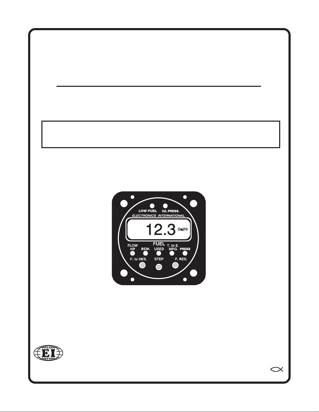
Primary Fuel Flow/PressurePrimary Fuel Flow/Pressure
Primary Fuel Flow/Pressure
Primary Fuel Flow/PressurePrimary Fuel Flow/Pressure
(FP-5-LxxHyy and FP-5L-LxxHyy)(FP-5-LxxHyy and FP-5L-LxxHyy)
(FP-5-LxxHyy and FP-5L-LxxHyy)
(FP-5-LxxHyy and FP-5L-LxxHyy)(FP-5-LxxHyy and FP-5L-LxxHyy)
Operating InstructionsOperating Instructions
Operating Instructions
Operating InstructionsOperating Instructions
OI 0505931P
You must read this manual before installing or operating the instrument. This
manual contains warranty and other information that may affect your decision
to install this product and/or the safety of your aircraft.
2/17/05
Electronics International Inc.Electronics International Inc.
Electronics International Inc.
Electronics International Inc.Electronics International Inc.
63296 Powell Butte Hwy • Bend, OR 97701 • (541) 318-6060 • www.Buy-EI.com
®®
®
®®
Page 2

Primary FP-5-LxxHyy and FP-5L-LxxHyy
Important NoticeImportant Notice
Important Notice
Important NoticeImportant Notice
********** Must Read ******************** Must Read **********
********** Must Read **********
********** Must Read ******************** Must Read **********
If you think it is not important to read this manual, you're wrong!If you think it is not important to read this manual, you're wrong!
If you think it is not important to read this manual, you're wrong!
If you think it is not important to read this manual, you're wrong!If you think it is not important to read this manual, you're wrong!
contains important information that may affect the safety of your aircraft.contains important information that may affect the safety of your aircraft.
contains important information that may affect the safety of your aircraft.
contains important information that may affect the safety of your aircraft.contains important information that may affect the safety of your aircraft.
Read the Warranty / AgreementRead the Warranty / Agreement
Read the Warranty / Agreement. There is information in the Warranty / Agreement that may alter
Read the Warranty / AgreementRead the Warranty / Agreement
your decision to install this product.
install this productinstall this product
install this product. This product may be returned for a refund. Contact Electronics International inc. for
install this productinstall this product
details.
The fuel remaining displayed by the FP-5 is not a measurement of the fuel in the tanks. It is an
amount calculated from the starting fuel level you programmed into the FP-5, minus the fuel used while the
engine was running. When properly calibrated, the FP-5 can accurately measure the fuel used. It is im-
perative the pilot verify the calibration of the FP-5 over many tanks of fuel before using the "REM"
and/or "USED" Modes as an indication of the fuel in the tanks or fuel used. Even after verifying the
calibration of the FP-5 it should never be used as the primary indicator of fuel quantity in the tanks.
It is important the pilot visually check/measure the fuel quantity for each tank before takeoff and
cross-check these readings against the Fuel Level Gauges and the FP-5. The FP-5 reminds you to do
this by blinking the “REM” LED and displaying the current fuel remaining in the tanks each time the
aircraft power is turned on. Also, it is important the pilot use preflight and flight planning techniques,
in accordance with the FAR's, which will help insure the proper amount of fuel for the intended
flight is on board the aircraft before takeoff.
While in flight the FP-5 readings should only be used to crosscheck fuel level gauges, calculations
of the fuel onboard from flow rates specified in the specification for your aircraft and calculations of
the fuel onboard from flow rates that you measured from previous flights. The use of the FP-5 does
not eliminate or reduce the necessity for the pilot to use good flight planning, preflight and in-flight
techniques for managing fuel. If you are not familiar with these techniques, contact the FAA to
acquire proper training.
If you do not accept the terms of the Warranty / Agreement, do notIf you do not accept the terms of the Warranty / Agreement, do not
If you do not accept the terms of the Warranty / Agreement, do not
If you do not accept the terms of the Warranty / Agreement, do notIf you do not accept the terms of the Warranty / Agreement, do not
This manual This manual
This manual
This manual This manual
Before leaning your engine you must verify your horsepower is correct with engine operation
charts from the engine and/or aircraft manufacturer to insure you do not cause detonation and
engine damage.
It is possible for any instrument to fail thereby displaying inaccurate high, low or jumpy readings.
Therefore, you must be able to recognize an instrument failure and you must be proficient in operating your
aircraft safely in spite of an instrument failure. If you do not have this knowledge, contact the FAA or a
local flight instructor for training. Also, the ability for this product to detect a problem is directly related to
the pilots ability to program proper limits and the pilots interpretation and observation skills.
The pilot
to operate the aircraft that does not know the operation of this product.
in the aircraft at all times.in the aircraft at all times.
in the aircraft at all times.
in the aircraft at all times.in the aircraft at all times.
must must
must understand the operation of this product before flying the aircraft. Do not allow anyone
must must
A copy of this manual must be keptA copy of this manual must be kept
A copy of this manual must be kept
A copy of this manual must be keptA copy of this manual must be kept
Page 3

Contents
WW
arranty ...................................................................................arranty ...................................................................................
W
arranty ...................................................................................
WW
arranty ...................................................................................arranty ...................................................................................
22
2
22
System Description: ................................................................System Description: ................................................................
System Description: ................................................................
System Description: ................................................................System Description: ................................................................
DisplayDisplay
Display
DisplayDisplay
1. Digital LCD Display and LED Display Mode Indicators: ---------------------------------- 4
2. Low Fuel Warning LED: ------------------------------------------------------------------------ 4
3. H/L PRESS Warning LED: ------------------------------------------------------------------- 5
4. Power-Up: ---------------------------------------------------------------------------------------- 5
Display Modes and Operating Features: .......................Display Modes and Operating Features: .......................
Display Modes and Operating Features: .......................
Display Modes and Operating Features: .......................Display Modes and Operating Features: .......................
1. “FLOW / HP” Display Mode: ---------------------------------------------------------------- 6
2. “REM” (Remaining) Display Mode: -------------------------------------------------------- 7
3. Auto Calibrate Mode: --------------------------------------------------------------------------- 8
4. Add Fuel: ----------------------------------------------------------------------------------------- 9
5. “USED” Display Mode: ----------------------------------------------------------------------- 10
6. “T. to E. / MPG" (Time to Empty / Miles per Gallon) Display Mode: ---------------- 11
7. “PRESS” (Fuel Pressure) Display Mode: -------------------------------------------------- 11
8. “F. to D. (Fuel to Destination) Display Mode (FP-5L only): --------------------------- 12
9. “F. Reserve (Fuel Reserve) Display Mode (FP-5L only): ------------------------------- 12
, W, W
arning LEDs, and Alarms: ......................................arning LEDs, and Alarms: ......................................
, W
arning LEDs, and Alarms: ......................................
, W, W
arning LEDs, and Alarms: ......................................arning LEDs, and Alarms: ......................................
33
3
33
44
4
44
55
5
55
Pilot-Programmable Settings: ........................................ 12Pilot-Programmable Settings: ........................................ 12
Pilot-Programmable Settings: ........................................ 12
Pilot-Programmable Settings: ........................................ 12Pilot-Programmable Settings: ........................................ 12
1. Setting the display for "Gal," "br Gal," "Lbs" or "Ltr" in the Flow Display Mode: ----- 13
Add Fuel and Auto Calibrate the K Factor: --------------------------------------------------- 13
2.
3. Setting the Two
4. Setting the Time to Empty Alarm and the Reoccurring Fuel Used Alarm in the
"T. to E." Display Mode: ----------------------------------------------------------------------- 15
Power-Up Programmable Settings: ................................ 16Power-Up Programmable Settings: ................................ 16
Power-Up Programmable Settings: ................................ 16
Power-Up Programmable Settings: ................................ 16Power-Up Programmable Settings: ................................ 16
1&2. 1st and 2nd Full Fuel Levels: ------------------------------------------------------------- 16
3. K Factor: ------------------------------------------------------------------------------------- 16
4. Filter: ----------------------------------------------------------------------------------------- 17
5. Display Update Time: --------------------------------------------------------------------- 17
6. Fuel Flow at 75% Power (rich mixture) Setting: -------------------------------------- 18
9. GPS Receive Format (FP-5L only): ------------------------------------------------------ 18
10. GPS Transmit Format (FP-5L only): --------------------------------------------------- 19
11. Scan Rate: ------------------------ ----------------------------------------------------------- 19
Specifications and Operating Features ......................... 20Specifications and Operating Features ......................... 20
Specifications and Operating Features ......................... 20
Specifications and Operating Features ......................... 20Specifications and Operating Features ......................... 20
Low Fuel Alarms in the "Used" Display Mode: --------------------------- 13
Page 4

WW
arranty / Agreementarranty / Agreement
W
arranty / Agreement
WW
arranty / Agreementarranty / Agreement
Electronics International Inc. (E.I. inc.) warrants this instrument and system components to be free from
defects in materials and workmanship for a period of one year from the user invoice date.
and Pressure Transducers are NOT covered under this warrantyand Pressure Transducers are NOT covered under this warranty
and Pressure Transducers are NOT covered under this warranty. They are covered by the original
and Pressure Transducers are NOT covered under this warrantyand Pressure Transducers are NOT covered under this warranty
equipment manufacturer. Electronics International Inc. will repair or replace any item, at its sole discretion, covered under the terms of this Warranty provided the item is returned to the factory prepaid.
1. This Warranty shall not apply to any product that has been repaired or altered by any person other
than Electronics International Inc., or that has been subjected to misuse, accident, incorrect wiring,
negligence, improper or unprofessional assembly or improper installation by any person.
does not cover any reimbursement for any person’s time for installation, removal, assembly or repair.does not cover any reimbursement for any person’s time for installation, removal, assembly or repair.
does not cover any reimbursement for any person’s time for installation, removal, assembly or repair.
does not cover any reimbursement for any person’s time for installation, removal, assembly or repair.does not cover any reimbursement for any person’s time for installation, removal, assembly or repair.
Electronics International retains the right to determine the reason or cause for warranty repair.
2. This Warranty does not extend to any machine, vehicle, boat, aircraft or any other device to which
the Electronics International Inc. product may be connected, attached, interconnected or used in conjunction with in any way.
3. The obligation assumed by Electronics International Inc. under this Warranty is limited to repair,
replacement or refund of the product, at the sole discretion of Electronics International Inc.
Fuel FlowFuel Flow
Fuel Flow
Fuel FlowFuel Flow
This warrantyThis warranty
This warranty
This warrantyThis warranty
4. Electronics International Inc. is not liable for expenses incurred by the customer or installer due to
factory updates, modifications, improvements, upgrades, changes, or any other alterations to the product
that may affect the form, fit, function or operation of the product.
5. Personal injury or property damage due to misinterpretation or lack of understanding of this product is solely
the pilot's responsibility. The pilot
not allow anyone to operate the aircraft that does not know the operation of this product. Keep the Operating
Manual in the aircraft at all times.
6. E. I. Inc. is not responsible for shipping charges or damages incurred under this Warranty.
7. No representative is authorized to assume any other liability for Electronics International Inc. in
connection with the sale of Electronics International Inc. products.
If you do not agree to and accept the terms of this Warranty, you may return the product for aIf you do not agree to and accept the terms of this Warranty, you may return the product for a
8.
If you do not agree to and accept the terms of this Warranty, you may return the product for a
If you do not agree to and accept the terms of this Warranty, you may return the product for aIf you do not agree to and accept the terms of this Warranty, you may return the product for a
refund.refund.
refund.
refund.refund.
This Warranty is made only to the original user.
WARRANTIES OR OBLIGATIONS: EXPRESS OR IMPLIED. MANUFACTURER EXPRESSLYWARRANTIES OR OBLIGATIONS: EXPRESS OR IMPLIED. MANUFACTURER EXPRESSLY
WARRANTIES OR OBLIGATIONS: EXPRESS OR IMPLIED. MANUFACTURER EXPRESSLY
WARRANTIES OR OBLIGATIONS: EXPRESS OR IMPLIED. MANUFACTURER EXPRESSLYWARRANTIES OR OBLIGATIONS: EXPRESS OR IMPLIED. MANUFACTURER EXPRESSLY
DISCLAIMS ALL IMPLIED WARRANTIES OF MERCHANTABILITY OR FITNESS FOR ADISCLAIMS ALL IMPLIED WARRANTIES OF MERCHANTABILITY OR FITNESS FOR A
DISCLAIMS ALL IMPLIED WARRANTIES OF MERCHANTABILITY OR FITNESS FOR A
DISCLAIMS ALL IMPLIED WARRANTIES OF MERCHANTABILITY OR FITNESS FOR ADISCLAIMS ALL IMPLIED WARRANTIES OF MERCHANTABILITY OR FITNESS FOR A
PARTICULAR PURPOSE. PURCHASER AGREES THAT IN NO EVENT SHALL MANUFAC-PARTICULAR PURPOSE. PURCHASER AGREES THAT IN NO EVENT SHALL MANUFAC-
PARTICULAR PURPOSE. PURCHASER AGREES THAT IN NO EVENT SHALL MANUFAC-
PARTICULAR PURPOSE. PURCHASER AGREES THAT IN NO EVENT SHALL MANUFAC-PARTICULAR PURPOSE. PURCHASER AGREES THAT IN NO EVENT SHALL MANUFACTURER BE LIABLE FOR SPECIAL, INCIDENTAL OR CONSEQUENTIAL DAMAGES, IN-TURER BE LIABLE FOR SPECIAL, INCIDENTAL OR CONSEQUENTIAL DAMAGES, IN-
TURER BE LIABLE FOR SPECIAL, INCIDENTAL OR CONSEQUENTIAL DAMAGES, IN-
TURER BE LIABLE FOR SPECIAL, INCIDENTAL OR CONSEQUENTIAL DAMAGES, IN-TURER BE LIABLE FOR SPECIAL, INCIDENTAL OR CONSEQUENTIAL DAMAGES, INCLUDING LOST PROFITS OR LOSS OF USE OR OTHER ECONOMIC LOSS. EXCEPT ASCLUDING LOST PROFITS OR LOSS OF USE OR OTHER ECONOMIC LOSS. EXCEPT AS
CLUDING LOST PROFITS OR LOSS OF USE OR OTHER ECONOMIC LOSS. EXCEPT AS
CLUDING LOST PROFITS OR LOSS OF USE OR OTHER ECONOMIC LOSS. EXCEPT ASCLUDING LOST PROFITS OR LOSS OF USE OR OTHER ECONOMIC LOSS. EXCEPT AS
EXPRESSLY PROVIDED HEREIN, MANUFACTURER DISCLAIMS ALL OTHER LIABILITYEXPRESSLY PROVIDED HEREIN, MANUFACTURER DISCLAIMS ALL OTHER LIABILITY
EXPRESSLY PROVIDED HEREIN, MANUFACTURER DISCLAIMS ALL OTHER LIABILITY
EXPRESSLY PROVIDED HEREIN, MANUFACTURER DISCLAIMS ALL OTHER LIABILITYEXPRESSLY PROVIDED HEREIN, MANUFACTURER DISCLAIMS ALL OTHER LIABILITY
TO PURCHASER OR ANY OTHER PERSON IN CONNECTION WITH THE USE OR PERFOR-TO PURCHASER OR ANY OTHER PERSON IN CONNECTION WITH THE USE OR PERFOR-
TO PURCHASER OR ANY OTHER PERSON IN CONNECTION WITH THE USE OR PERFOR-
TO PURCHASER OR ANY OTHER PERSON IN CONNECTION WITH THE USE OR PERFOR-TO PURCHASER OR ANY OTHER PERSON IN CONNECTION WITH THE USE OR PERFORMANCE OF MANUFACTURER’S PRODUCTS, INCLUDING SPECIFICALLY LIABILITY INMANCE OF MANUFACTURER’S PRODUCTS, INCLUDING SPECIFICALLY LIABILITY IN
MANCE OF MANUFACTURER’S PRODUCTS, INCLUDING SPECIFICALLY LIABILITY IN
MANCE OF MANUFACTURER’S PRODUCTS, INCLUDING SPECIFICALLY LIABILITY INMANCE OF MANUFACTURER’S PRODUCTS, INCLUDING SPECIFICALLY LIABILITY IN
TORT.TORT.
TORT.
TORT.TORT.
must must
must understand the operation of this product before flying the aircraft. Do
must must
THIS WARRANTY IS IN LIEU OF ALL OTHERTHIS WARRANTY IS IN LIEU OF ALL OTHER
THIS WARRANTY IS IN LIEU OF ALL OTHER
THIS WARRANTY IS IN LIEU OF ALL OTHERTHIS WARRANTY IS IN LIEU OF ALL OTHER
2
Page 5
Primary FP-5-LxxHyy and FP-5L-LxxHyy
Operating Instructions
System Description:System Description:
System Description:
System Description:System Description:
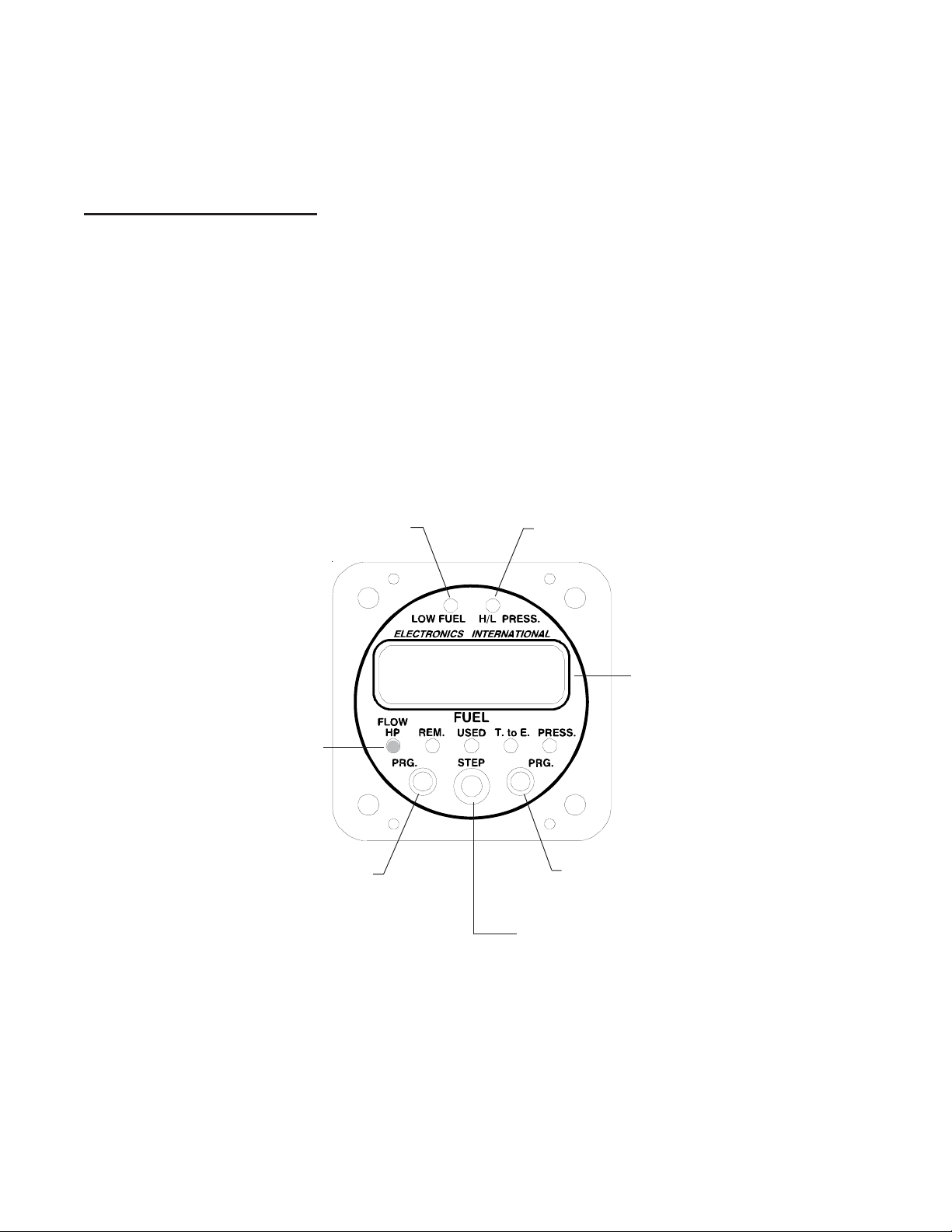
The Primary FP-5-LxxHyy and Primary FP-5L-LxxHyy are models of a fuel flow computer instrument
packaged in a 2.5" by 2.5" by 3.65" depth case. Each of the instruments connects to a fuel flow transducer and a
fuel pressure transducer which are mounted in the engine cowling area.
The fuel flow transducer is mounted in the fuel line going to the carburetor (or flow divider on an injected
engine). If the rotor in the flow transducer becomes blocked, it will not reduce the flow of fuel to the engine. The
FP-5(L) instrument connects to the transducers via a wire harness. The instrument and transducers employ
connectors so they may be removed safely and quickly from the aircraft.
The FP-5 and FP-5L each have seven display modes: Fuel Flow, Horsepower, Fuel Remaining, Fuel Used
Since Fill Up, Fuel Used for the Flight, Time to Empty, and Fuel Pressure. The FP-5L has all the features of the
FP-5, with four additional display modes: Nautical Miles per Gal, Statute Miles per Gal, Fuel to Destination and
Fuel Reserve.
Low Fuel Warning LED
High/Low Fuel Pressure Warning LED
Gal/Hr
LCD Display
12.3
Display Mode Indicator LEDs
Left Program Button
(Fuel to Destination on the FP-5L)
In addition to these seven display modes both units have the following pilot programmable settings (used to set
up the display and alarms): Display in Gallons, British (Imperial) Gallons, Pounds or Liters; Fuel Remaining; Auto
Calibrate the K Factor; two Low Fuel Alarms; Time to Empty Alarm; Reoccurring Fuel Used Alarm. Also, both
units have Power-Up Programmable Settings that are used to configure the instrument for your personal preferences, aircraft and engine. Although the FP-5 and FP-5L are simple to operate, the pilot programmable settings
make them very effective and sophisticated fuel management systems.
Right Program Button
(Fuel Reserve on the FP-5L)
Step Switch (selects modes)
Note: After the FP-5(L) has been installed in an aircraft it should be programmed initially as described in the
"Power-Up Programming" section of this Manual.
3
Page 6
Displays , WDisplays , W
Displays , W
Displays , WDisplays , W
1. Digital LCD Display and LED Display Mode Indicators:
If the digital LCD display backlight has been permanently powered up (as recommended), the display will be
easier to see during low ambient light conditions and at night. In direct sunlight the digital LCD display is easy to
see.
During night operation the green LED Display Mode Indicators may be too bright. If the LED Dimming
Line on the FP-5(L) is connected to your panel light rheostat, turning the rheostat up will dim the LEDs. If the
LED Dimming Line is connected to E.I.'s CP-1 (LED Intensity Control Pot), the Pot will control the LED intensity, independent of other instrument lights. The two red Warning LEDs will always be displayed at full intensity.
2. Low Fuel Warning LED:
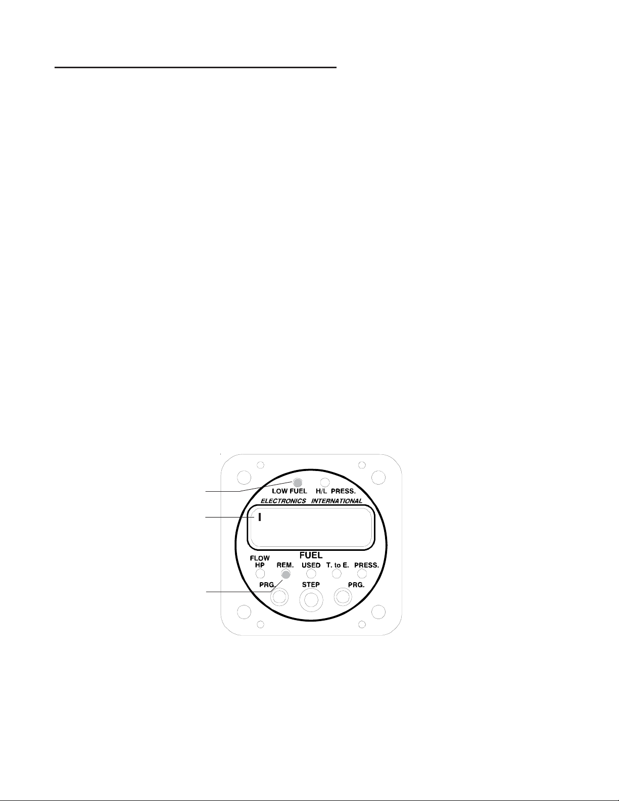
There are four pilot-programmable alarms that will blink the red Low Fuel Warning LED when violated.
The following describes how each alarm affects the Low Fuel Warning LED:
A. First Low Fuel Alarm: This alarm should be set as a reminder (example: 1/3 tank level). When the
Alarm Limit is violated the red Low Fuel Warning LED will start to blink. Pushing any button or
switch will stop the blinking and turn off the Warning LED. Also, a bar in the upper left corner of
the display will be shown when displaying “REM”.
arning LEDs and Alarms:arning LEDs and Alarms:
arning LEDs and Alarms:
arning LEDs and Alarms:arning LEDs and Alarms:
B. Second Low Fuel Alarm: This alarm should be set as a warning (example: 5 gallons). When the
Alarm Limit is violated the red Low Fuel Warning LED will start to blink. Pushing any button or
switch will stop the blinking and the LED will go solid red. Also, a bar in the lower left corner of
the display will be shown when displaying “REM”.
C. Time to Empty Alarm: This alarm may be set for a time to empty value (example: 1 hour). When
Note: In this example, the First
Low Fuel Limit was set to 12.0
Low Fuel Warning LED
(blinking)
Upper Bar Showing
Gal
Gallons. The blinking Low Fuel
Warning LED indicates that the
limit was violated.
11.9
Mode: "REM."
the fuel flow and fuel remaining results in less than one hour of fuel on board (as per example) the
Alarm Limit is violated and the red Low Fuel Warning LED will start to blink. Pushing any button or
switch will stop the blinking and turn off the Warning LED. Also, a bar in the upper left corner of the
display will be shown when displaying "T.toE."
4
Page 7

D. Reoccurring Fuel Used Alarm: This alarm may be set for a fuel used value (example: 10 Gal). If
the alarm was activated with 40 gallons of fuel remaining, there will be an alarm at 30, 20 and 10
gallons of fuel remaining in the tank. This feature reminds you to switch tanks for balancing the
wings (based on weight, not time) or it may be used to remind you to check your fuel levels at set
intervals. When the Alarm Limit is violated the red Low Fuel Warning LED will start to blink.
Pushing any button or switch will stop the blinking and turn off the Warning LED.
Note: See the "Pilot Programmable Modes" section of this manual to set the alarms.
3. H/L Pressure Warning LED:
The factory set High and Low Alarm Limits will blink the red "H/L PRESS" Warning LED when violated.
The limits were set when the instrument was shipped from the factory. The limits were set according to the
customer supplied high and low limits from their POH or AFM. Pushing any button or switch will cause the LED
to stop blinking and become solid red. If the High Limit is violated, a bar in the upper left corner of the display will
be shown when displaying “PRESS" If the Low Limit is violated, a bar in the lower left corner of the display will
be shown when displaying “PRESS”.
4. Power-Up:
When the aircraft master switch is turned on, the FP-5(L) will perform a self-diagnostics test and flash the
red warning LEDs. This allows you to check the Warning LEDs for proper operation.
After power-up, the FP-5(L) will blink the "REM" (Fuel Remaining) LED, and display the fuel remaining in
the tank(s). The “REM” LED will continue to blink until any button or switch is pushed. The blinking “REM”
LED is intended as a reminder to update the FP-5(L) if you’ve added fuel to the aircraft since your last flight (see
“REM” Display Mode).
Display Modes and Operating Features:Display Modes and Operating Features:
Display Modes and Operating Features:
Display Modes and Operating Features:Display Modes and Operating Features:
The following chart is an overview of the Display Modes and Pilot Programmable Settings available.
Main Display
(select with
"STEP" Switch)
Alternate Display
(tap either " P RG"
button)
Pilot
Programmable
Settings
(push both "PRG"
buttons)
Di splay Mode
FLOW
HP REM USED
Fuel Flow
(17.3 gal/Hr)
Horsepower
(HP75)
Set FP-5(L)
to Display in
Gal, Br Gal,
Lbs or Lt rs .
%
Fuel Remaining
(23.7 gal)
Add Fuel
("Add")
Auto Calibrate
the K Factor
("AUTO")
(indicated by a green LED)
T. t o E .
MPG PRESS
Fuel Used
since Fill Up
(16.3 gal)
Fuel Used for
the F light
(F 7.2 gal)
Set the First
Low F ue l
Alarm
(High Ba r )
Set the
Second Low
Fuel Alarm
(Low Bar)
Time t o E m pt y
(1:22)
(FP-5L only)
Nautical Miles
per Gallon
(n 9.3)
(FP-5L only)
Statute Miles
per Gallon
( 10.7)
Set the Time to
Empty Alarm
(High Bar)
Set the
Reoccurring Fuel
Used Alarm
(Low Bar)
Fuel
Pressure
5
Page 8
1. “FLOW / HP” Display Modes:
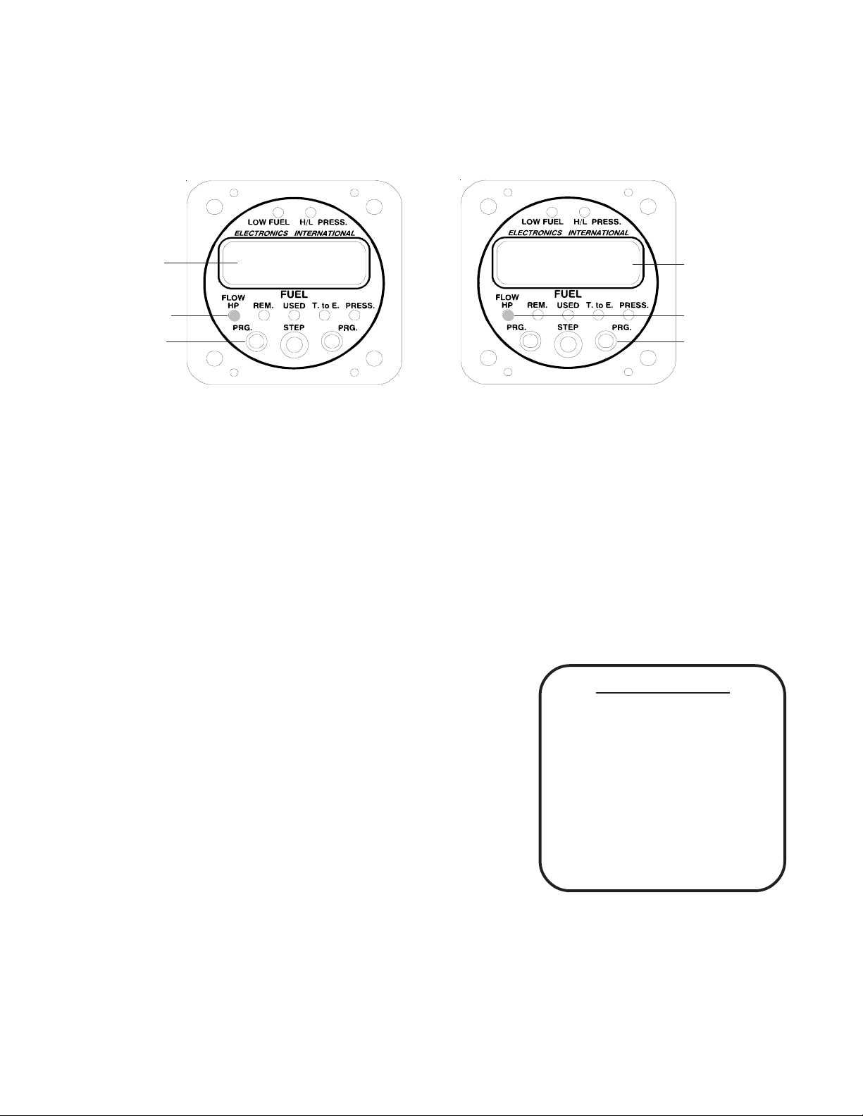
By pushing the mode select switch to the right or left, you can select the various display modes. When in the
"Flow / HP" mode, tapping either "PRG" button will cause the display to toggle between displaying Fuel Flow and
percentage of Horsepower. When displaying Horsepower, "HP" will be shown at the left of the display.
Flow Displayed
Flow / HP Mode
Tap either Prg
Button to toggle
between the two
displays.
12.3
Gal/Hr
HP75
75% Horsepower
Displayed.
Flow / HP Mode
Tap either Prg
Button to toggle
between the two
displays.
When displaying Fuel Flow, the FP-5(L) will operate as follows:
A. When set to display in Gallons the display will read in .1 Gal/Hr increments up to 199.9 Gal/Hr.
B. When set to display in Imperial Gallons the display will read in .1 Gal/Hr increments up to 162.0 Gal/
Hr.
C. When set to display in Pounds the display will read in 1 Lb/Hr increments up to 1199 Lbs/Hr.
D. When set to display in Liters the display will read in 1 Ltr/Hr increments up to 749 Ltrs/Hr.
Special algorithms in the microprocessor are used to insure a quick response and a stable display. Also, there
are two programmable filter settings that will affect the stability and response of the fuel flow readings (see the
“Power-up Programmable Settings” section of this manual).
The accuracy of the displayed fuel flow is affected by the value of the
K Factor. The K Factor sets the calibration of the instrument to match
the flow transducer and the variations in the installation. The K Factor
may be changed by entering the "Power-up Programming Mode" or it
can be changed automatically by entering the "Auto Calibration Mode."
When displaying % Horsepower, the FP-5(L) will operate as
follows:
A. Horsepower is calculated from fuel specifics (as is done
on engine dyno's) which takes into account manifold
pressure, RPM, altitude and OAT. Almost all spark ignition combustion engines have a fuel specific
of approximately .10 gallons per H.P. per hour at full rich mixture. The "Power-Up Programming
Mode" allows you to calibrate the FP-5(L) to match your engine at a full rich mixture.
B. As you lean for max power (100° to 150°F rich of peak EGT) you may see a 5% to 8% drop in the
6
What is a K Factor:
Each flow transducer outputs a
different number of electical pulses
for each gallon of fuel that flows
through it. This value is called the
K Factor. The FT-60 has a K
Factor of approximately 68,000
pulses per gallon. The installation
and the type of engine (carbureted
or injected) can affect the K Factor.
Page 9

displayed horsepower when you should see an approximately 3% increase in horsepower. Therefore, only display "HP" when your engine is running at full rich mixture settings.
C. The FP-5(L) was designed to display in % Horsepower (1% resolution). It is possible to calibrate the
FP-5(L) to display in raw horsepower. See the "Power-Up Programming Mode."
Warning: You should never lean your engine with power settings over the factory recommended
level (generally 65% to 75% power). Leaning with high power settings can cause detonation. Always verify
your power level with engine charts before leaning. As you lean past maximum horsepower (100°F to 150°F rich
of peak EGT) your engine will lose power and the FP-5(L) will show this.
2. “REM” (Remaining) Display Mode:
In the “REM” (Fuel Remaining) Display Mode, the FP-5(L) will display
the fuel in the aircraft tanks as follows:
A. When set to display in Gallons the display will read in .1 Gal
increments up to 99.9 Gals. and 1 Gal increments from 100 to
999 Gals.
B. When set to display in Imperial Gallons the display will read in
.1 Gal increments up to 99.9 Gals. and 1 Gal increments from
100 to 811 Gals.
25.3
Gal
C. When set to display in Pounds the display will read in 1 Lb
increments up to 1999 Lbs.
D. When set to display in Liters the display will read in 1 Ltr increments up to 1999 Ltrs.
If the First Low Fuel Limit has been violated, a bar in the upper left corner of the display will be shown when
this mode is selected. If the Second Low Fuel Limit has been violated, a bar in the lower left corner of the display
will be shown when this mode is selected. See the "Pilot Programmable Settings" section of this manual to set the
two Low Fuel Limits.
Warning: The fuel remaining displayed by the FP-5(L) is not a measurement of the fuel in the tanks.
It is an amount calculated from the starting fuel level you programmed into the FP-5, minus the fuel used while the
engine was running. When properly calibrated, the FP-5(L) can accurately measure the fuel used. It is impera-
tive the pilot verify the calibration of the FP-5(L) over many tanks of fuel before using the "REM" and/
or "USED" Modes as an indication of the fuel in the tanks or fuel used. Even after verifying the
calibration of the FP-5(L) it should never be used as the primary indicator of fuel quantity in the tanks.
It is important the pilot visually check/measure the fuel quantity for each tank before takeoff and crosscheck these readings against the fuel level gauges and the FP-5. The FP-5(L) reminds you to do this by
blinking the “REM” LED and displaying the current fuel remaining in the tanks each time the aircraft power is
turned on. Also, it is important the pilot use preflight and flight planning techniques, in accordance with
the FARs, which will help insure the proper amount of fuel is on board the aircraft before takeoff.
7
Page 10

While in flight the FP-5(L) readings should only be used to cross-check the fuel level gauges, calculations of the fuel on board from flow rates specified in the specification for your aircraft and calculations
of the fuel on board from flow rates that you measured from previous flights. The use of the FP-5(L)
does not eliminate or reduce the necessity for the pilot to use good flight planning, preflight and inflight techniques for managing fuel. If you are not familiar with these techniques, contact the FAA to
acquire proper training.
3. Auto Calibrate Mode:
If you find the FP-5(L) is not displaying the Fuel Remaining in the tank(s) or Fuel Used Since Fill Up accurately, you can enter the "Auto Calibrate Mode" and have the FP-5(L) automatically calibrate the K Factor. This
should be done when you have used more than 1/2 tank of fuel and you have just filled the tank(s) with fuel.
Example:
* You start your flight with full tank(s) and go fly.
* You land and pull up to the pumps, taking on 30.0 gallons of fuel.
* The FP-5(L) indicates you used 26.9 gallons since fill up, indicating a 3.1 gallon error.
* You enter the "Auto Calibrate Mode" (as described below) and change the display from 26.9 to 30.0
(pump reading).
* When you exit the "Auto Calibrate Mode" the New K Factor is displayed for 3 seconds.
Note: If you want the FP-5(L) to automatically calibrate the K Factor, you must enter the "Auto Calibrate Mode"
before entering the "Add Fuel Mode." When you exit the "Add Fuel Mode" the "Fuel Used Since Fill Up" will be
cleared and the FP-5(L) will not be able to calculate the new K Factor.
Note: When calibrating the K Factor it is important to fill the tank(s) to same level each time (which is not
always easy). Some variables are: 1. How level the wings are during refueling. 2. The affects of any crossover
tubes. 3. The ability of the line attendant to fill the tank to the same mark. 4. The shape of the tank and the
dihedral of the wings.
Normally you will only need to calibrate the K Factor during the first three or four tanks of fuel after the
initial installation. The FP-5(L) uses a progressive algorithm to calibrate the K Factor and to keep the instrument
from hunting for the correct K Factor. To enter the "Auto
Calibrate Mode", perform the following steps:
A. Select the “REM” display mode.
B. Momentarily push both "PRG" buttons at the
same time. The display will blink “Add."
Blinking Display
AUto
C. While pushing and holding the left "PRG"
button, push the "STEP" Switch right or left to
display "Auto."
8
SS
Step Switch Toggles
SS
the display between
"Add" and "Auto."
Page 11

D. Tap either one of the “PRG” buttons and the FP-5(L) will display the "Fuel Used Since Fill Up"
according to its current calibration. The blinking left digit indicates that you may program this digit.
E. Program the display to show the fuel you actually used as indicated by
the fuel pump as follows:
Select a Digit - The Right and Left “PRG” buttons move the blinking
a)
digit to the right or to the left.
b) Advance a Digits Count - Moving the "STEP Switch" to the right will increase the blinking digits
count by one and moving the "STEP Switch" to the left will decrease the blinking digits count by
one. After the blinking digit reaches 9 it will reset to 0.
c) To Exit - To exit the "Auto Calibration Mode", momentarily push both “PRG” buttons at the
same time. The new K Factor will be displayed for 3 seconds and the display will return to
blinking "Add." Most of the time you will want to enter the "Add Fuel Mode" after you have
performed an auto calibration (see "Add Fuel").
Note: After exiting the "Auto Calibrate Mode", the "Fuel Used Since Fill Up", "Fuel Used for the Flight" and the
"Fuel Remaining" values will be reset to 0.
4. Add Fuel:
If you have added fuel to the aircraft but have not filled the tanks, set the FP-5(L) "REM" value for the
fuel remaining shown on the FP-5, plus the fuel added to the tank(s) as shown on the fuel pump. If you have filled
the tank(s), set the FP-5(L) "REM" value for the total fuel in the tanks. There are two pre-programmed full fuel
levels you may recall automatically. It is important to verify the fuel levels in the tanks before takeoff.
Blinking Digit
Gal
26.9
To change the Fuel Remaining shown on the FP-5(L), perform the following steps:
A. Select the “REM” display mode (this
mode is displayed during power-up).
B. Momentarily push both "PRG" buttons at
the same time. The display will blink
"Add."
C. Push either one of the “PRG” buttons.
The display will show the current fuel
remaining. The blinking left digit indicates that you may program this digit
first.
D. Set the Fuel Remaining Level using the following procedure (if you have topped off the tank, see step
"c)" below):
a) Select a Digit - The Right and Left “PRG” buttons move the blinking digit to the right or to the
left.
b) Increase or Decrease a Digits Count - Moving the "STEP Switch" to the right will increase the
blinking digits count and moving it to the left will decrease the blinking digits count.
Blinking Digit (0)
"Prg." buttons select
the blinking digit.
Step Switch increases
or decreases the value
of the blinking digit.
9
026
Gal
Page 12
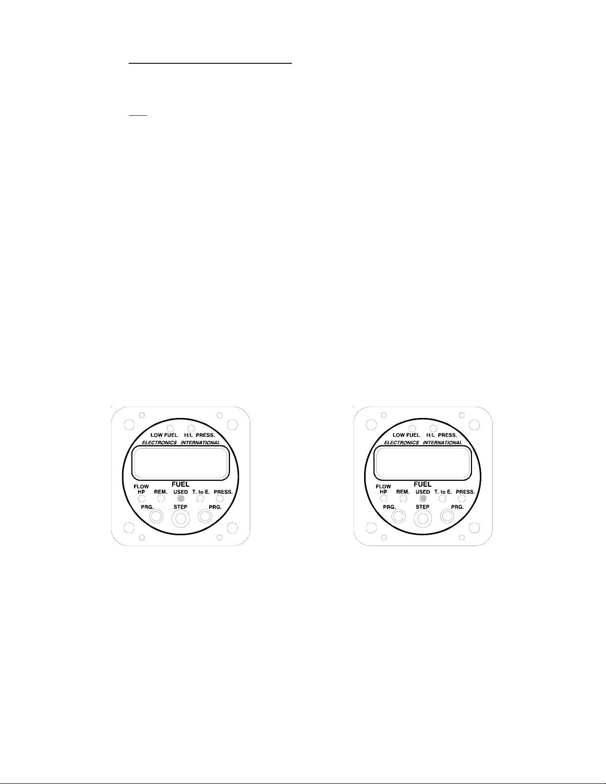
c) Call up a pre-programmed Fuel Level - If you push and hold the left "PRG" button, the display
will cycle between the two pre-programmed fuel levels (set during Power-Up Programming) and
the current fuel level every two seconds.
d)
Exit - To exit the "Add Fuel Mode", momentarily push both “PRG” buttons at the same time.
The programmed value will be stored in memory and no internal batteries or external power are
required to store this information for life.
Fuel Remaining is one of the most important calculations the FP-5(L) can provide. The differences between
the flow transducers, elbows, fittings, pipe sizes, hoses and routing methods used during installation for any fuel
flow instrument can cause the flow transducer to output different electrical pulses per gallon (called K Factor)
than when it was tested at the factory. To insure accuracy, which is essential, the FP-5(L) provides a pilotprogrammable K Factor to correct for these differences. Initially, the FP-5(L)'s K Factor is set to a value which is
marked on a tag supplied with the flow transducer. At each fill up the K factor may be changed using the "Auto
Calibrate Mode" or the K Factor may be manually changed in the Power-up Programming.
5. “USED” Display Mode:
In the “USED” Display Mode, the FP-5(L) will display the "Fuel Used Since Fill Up." By tapping either
"PRG" button the display will toggle between "Fuel Used Since Fill Up" and "Fuel Used for the Flight" (displayed
with a "F" in the front of the value). The Fuel Used for the Flight is measured from the time the aircraft's electrical power was turned on. If the electrical power is turned off, the Fuel Used for the Flight will reset to "000." The
"Fuel Used Since Fill Up" is held in permanent memory and reset to "000" when you enter the "Add Fuel" or "Auto
Calibrate" modes.
Note: Tap either "Prg" Button to toggle between the two displays.
Gal
22.8
"Fuel Used Since Fill Up" Displayed
The "Fuel Used Since Fill Up" and the "Fuel Used for the Flight" is displayed as follows:
A. When set to display in Gallons the display will read in .1 Gal increments up to 99.9 Gals and 1 Gal
increments up to 999 Gals.
B. When set to display in Imperial Gallons the display will read in .1 Gal increments up to 99.9 Gals and
1 Gal increments up to 811 Gals.
"Fuel Used for the Flight" Displayed
F 8.7
Gal
C. When set to display in Pounds the display will read in 1 Lb increments up to 1999 Lbs.
10
Page 13
D. When set to display in Liters the display will read in 1 Ltr increments up to 1999 Ltrs.
The K Factor programmed into the FP-5(L) will affect the fuel used. See the “Pilot-Programmable Modes”
section in this manual for further details.
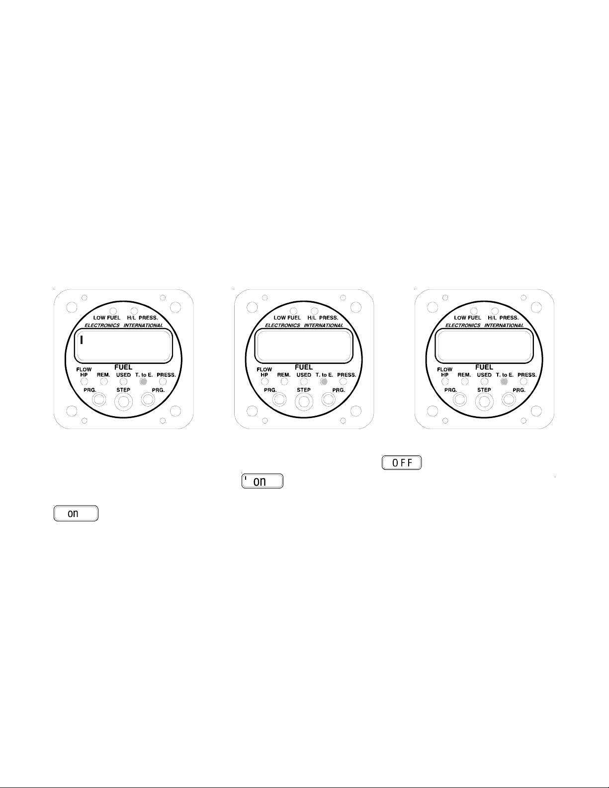
6. “T. to E. / MPG” (Time to Empty / Miles per Gallon) Display Mode:
"Time to Empty" is calculated by dividing "Fuel Remaining" by "Fuel Flow". The value is displayed in hours
and minutes up to 19 hours and 59 minutes. By tapping either "PRG" button, the FP-5L can be toggle between
"Time to Empty", "Nautical Miles per Gallon" (shown with a "n" in the left of the display) and "Statute Miles per
Gallon."
If the programmable Low "T. to E." Limit has been violated (as shown in the left display below), a bar in the
upper left corner of the display will be shown when displaying Time to Empty. See the "Pilot Programmable
Settings" section of this manual to set the Time to Empty Limit.
Note: Tap either "PRG" button to toggle between the different displays.
1:22 n 9.3 10.7
Time to Empty Displayed
If the FP-5L is not receiving data from a GPS, the display will show " ." If a signal is present but the
baud rate is wrong, the display will show "
If the baud rate is correct but the ground speed and distance to waypoint is not available, the display will show "
." To set up the FP-5(L) to receive GPS data, see the "Power-Up Programmable Settings" sections of
this manual.
7. “PRESS” (Fuel Pressure) Display Mode:
The "PRESS" mode, the FP-5(L) will display fuel pressure in .2 PSI increments from .5 to 999.9 PSI. Readings below .5 PSI will be displayed as "000".
If the factory set High Fuel Pressure Limit is violated, a bar will appear in the upper left corner of the LCD
display in the “PRESS” mode, and the H/L PRESS Warning LED will blink. If the factory set Low Fuel Pressure
Limit is violated, a bar will appear in the lower left corner of the LCD display in the “PRESS” mode, and the H/L
PRESS Warning LED will blink.
Nautical Miles per Gallon Displayed Statute Miles per Gallon Displayed
" (note the tick mark in the upper left corner of the display).
11
Page 14
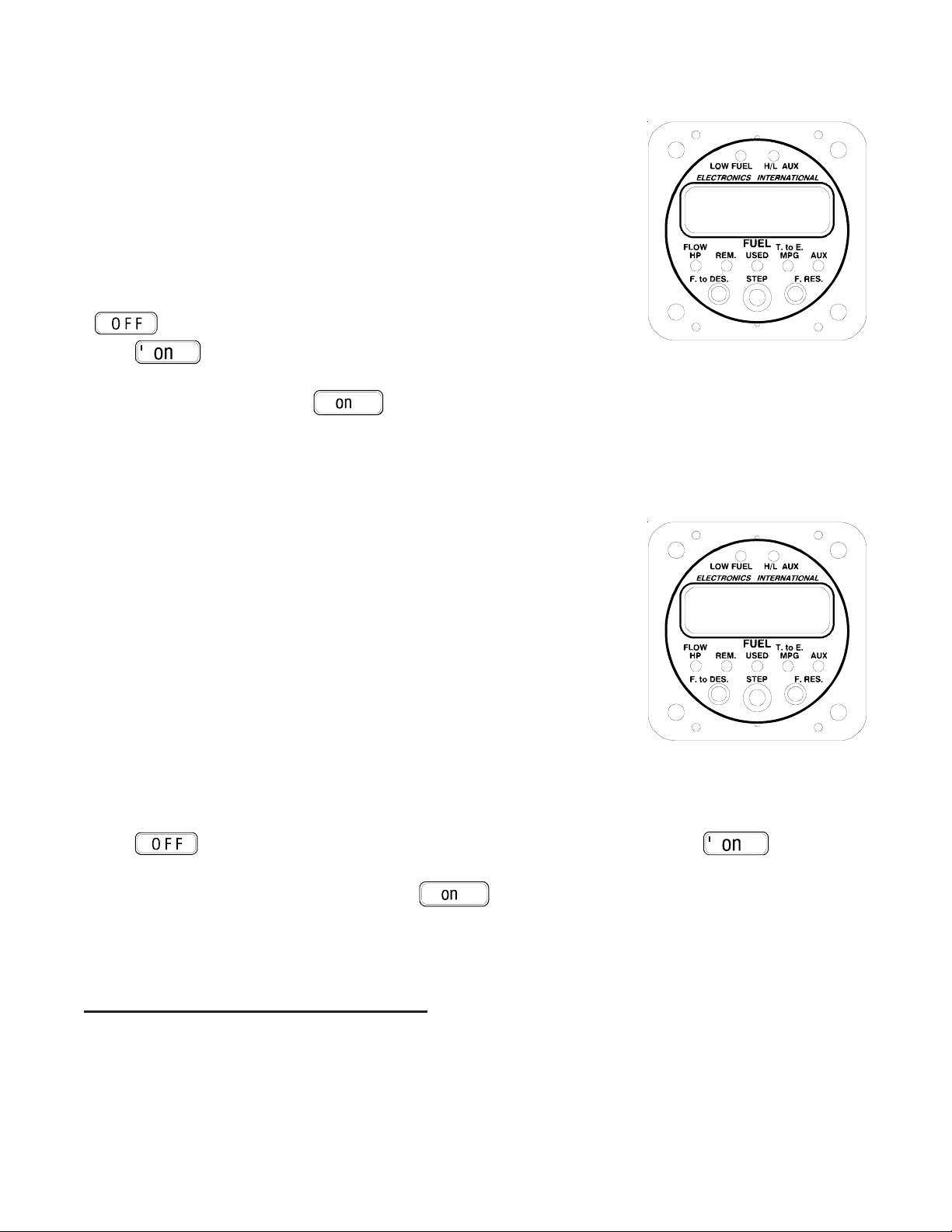
8. “F. to D. (Fuel to Destination) Display Mode (FP-5L only):
When the left button ("F. to DES") is pushed the FP-5L will read the serial
data from your GPS unit and compute the Fuel to Destination (next waypoint)
for the current conditions: Fuel Flow, Fuel Remaining, Ground Speed and
Distance to Destination. This process will take from one to three seconds
depending on the update time of your GPS unit. If the fuel required to reach
the waypoint is more than the fuel remaining as shown on the FP-5L, the "Low
Fuel Warning" LED will come on.
If the FP-5L is not receiving data from a GPS, the display will show
"
." If a signal is present but the baud rate is wrong, the display will
Gal
14.4
show "
If the baud rate is correct but the ground speed and distance to way point is not
available, the display will show "
GPS data, see the "Power-Up Programmable Settings" sections of this manual. Once speed and distance data
have been received, the Fuel to Destination (next waypoint) will be computed instantly and displayed on the FP5L.
9. “F. Reserve (Fuel Reserve) Display Mode (FP-5L only):
When the right button ("F. RES") is pushed the FP-5L will read the serial
data from your GPS unit and compute the Fuel Reserve for the current conditions: Fuel Flow, Fuel Remaining, Ground Speed and Distance to Destination.
The Fuel Reserve is the fuel you will have in your tank once you reach your
destination (next waypoint) programmed on the GPS unit (Fuel Reserve = Fuel
Remaining - Fuel to Destination). If the fuel required to reach the waypoint is
more than the fuel remaining as shown on the FP-5L, the Low Fuel Warning
LED will come on and the Fuel Reserve will be displayed as a negative number
(i.e., " -3" would mean you are 3 gallons short of reaching your destination).
When the "F. RES" button is pushed it will take from one to two sec-
onds, depending on the update time of your GPS unit, to read and compute the
serial data. If the FP-5L is not receiving data from a GPS, the display will
show "
tick mark in the upper left corner of the display). If the baud rate is correct but the ground speed and distance to
" (note the tick mark in the upper left corner of the display).
." To set up the FP-5L to receive
Distance = 180nm
Speed = 150n/hr
Fuel Flow = 12.0 Gal/Hr
Gal
3.9
Distance = 180nm
Speed = 150n/hr
Fuel Flow = 12.0 Gal/Hr
Fuel Rem. = 18.3
." If a signal is present but the baud rate is wrong, the display will show " " (note the
waypoint is not available, the display will show "
FP-5L to receive GPS data, see the "Power-Up Programmable Settings" sections of this manual. Once speed and
distance data have been received, Fuel Reserve will be computed instantly and displayed on the FP-5L.
Pilot-Programmable Settings:Pilot-Programmable Settings:
Pilot-Programmable Settings:
Pilot-Programmable Settings:Pilot-Programmable Settings:
The FP-5(L) has seven Pilot Programmable Settings. These programmable settings are what make the FP5(L) versatile, accurate and so effective at managing fuel. Most of these programmable settings need to be set
only once to match your engine and desired warning levels. The following chart is an overview of the Display
Modes and Pilot Programmable Settings available.
." To set up the
12
Page 15

Di spl ay Mode
(indicated by a green LED)
Main Display
(select w ith
"STEP" Switch)
Al t ern at e D i spl ay
(tap either " PRG"
button)
Pilot
Programmable
Settings
(push both " PRG"
buttons)
FLOW
HP REM USED
Fuel Flow
(17.3 gal/Hr)
%
Horsepower
(HP75)
Set FP-5(L)
t o D isp lay in
Gal, Br Ga l,
Lbs o r Lt rs .
F u e l R ema inin g
(23.7 gal)
Add Fuel
("Add")
Auto Ca lib ra te
the K F ac tor
("AU T O")
Fuel Used
since Fill Up
(16.3 gal)
Fuel Used for
the Flight
(F 7.2 gal)
Se t the First
Low Fue l
Alarm
(High Bar)
Se t the
Second Low
Fuel Alarm
(Low Bar)
T. t o E .
MPG PRESS
Time t o E m pt y
(1:22)
(FP-5L only)
Naut ica l M iles
per Gallon
(n 9.3)
(FP-5L only)
Statute Miles
per Gallon
( 10.7)
Se t the Time to
Empty Alar m
(High Bar)
Se t the
Reoccurring Fuel
Used Alarm
(Low Bar)
Fuel
Pressure
Although programming may be new to some of you, programming the FP-5(L) is simple. After a few tries,
you should have the hang of it. No matter which buttons you push or parameter you set you cannot hurt the
FP-5(L) and any parameter can be reset.
1. Setting the display for
In the "FLOW" Display Mode the FP-5(L) may be set to display Fuel Flow, Fuel Remaining and Fuel Used in
Gallons, British (Imperial) Gallons, Pounds or Liters.
To program the display, perform the following steps:
A. Select the “FLOW” Display Mode.
B. Momentarily push both “PRG” buttons. Either “Gal", "br Gal",
"Lbs" or “Ltr” will be shown in the display. You are ready to
program the FP-5(L) to display in Gallons, British (Imperial)
gallons, Pounds or Liters.
“Gal”, "br Gal", “Lbs” or "Ltr" in the "Flow" Display Mode:
13
g
Gal
AL
Page 16

C. Set the Display using the following procedure:
To change the display to "Gal", "br Gal", "Lbs" or "Ltr" - Moving the Mode Select Switch to the
a)
left while pushing the left program button will alternate the display between "Gal", "br Gal", "Lbs"
and "Ltr".
b) To Exit - To exit the Pilot Programming Settings for the "FLOW" Display Mode, momentarily
push both “PRG” buttons at the same time. The programmed values will be stored in memory
and internal batteries or external power are not required to store this information for life.
2. Add Fuel and Auto Calibrate the K Factor:
This procedure was described previously in the “Display Modes and Operating Features” section of this
manual.
3. Setting the Two Low Fuel Alarms in the "Used" Display Mode:
In the "USED" Display Mode the following alarms may be set:
First Low Fuel Alarm - The First Low Fuel Alarm may be programmed to blink the "Low Fuel Warning"
LED when the fuel remaining reaches your programmed set point. Pushing any button or switch will turn off
the blinking LED. This limit is intended as a reminder. It may be set to remind you to switch tanks or when a
specified amount of fuel remaining in the tanks has been reached. A good point to use in setting this alarm is
at the 1/2 fuel remaining level. In the “REM” Display Mode a bar in the upper left corner of the display will
be shown when the 1st Low Fuel Alarm Limit has been violated. Programming this alarm to “000” disables
the alarm.
Second Low Fuel Alarm - The Second Low Fuel alarm may be programmed to blink the "Low Fuel Warn-
ing" LED when the fuel remaining reaches your programmed setpoint. Pushing any button or switch will stop
the blinking but the Low Fuel Warning LED will stay on. This limit is intended as an emergency warn-
ing. It should be set to the lowest acceptable or safe fuel level in the tanks. A good point to use in setting
this alarm is 30 minutes’ worth of fuel (at cruise) for a VFR pilot or 45 minutes for an IFR pilot. In the
“REM” display mode a bar in the lower left corner of the display will be shown when the Second Low Fuel
Alarm Limit has been violated. Programming this alarm to “000” disables the alarm.
To program the First and Second Low Fuel Alarm Limits, perform the following steps:
A. Select the “USED” Display Mode.
B. Momentarily push both “PRG” buttons. A bar will appear in the
upper left corner of the display and the left digit will be blinking.
You are ready to program the 1st Low Fuel Alarm Limit.
C. Set the 1st and 2nd Low Fuel Alarm Limits using the following
procedure:
a) Select a Digit - The Right and Left “PRG” buttons move the
blinking digit to the right or to the left.
14
Blinking Digit (0)
Gal
015
Page 17
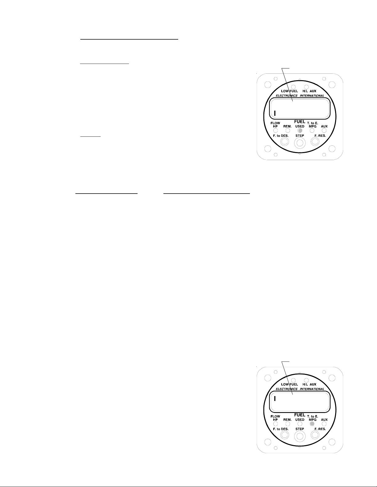
b) Increase or Decrease a Digits Count - Moving the "STEP" Switch to the right will increase the
blinking digits count and moving it to the left will decrease the blinking digits count.
c) Change Functions - The display will toggle between the First
and Second Low Fuel Alarm Limits by pushing the Right
"PRG" button with the right digit blinking or by pushing the
Left "PRG" button with the left digit blinking. The First Low
Fuel Alarm Limit is always displayed with a bar in the upper
left corner of the display and the Second Low Fuel Alarm
Limit is always displayed with a bar in the lower left corner of
the display.
d)
To Exit - To exit the Pilot Programming Settings for the
"USED" Display Mode, momentarily push both “PRG” buttons
at the same time. The programmed values will be stored in
memory and no internal batteries or external power are
required to store this information for life.
4. Setting the Time to Empty Alarm and the Reoccurring Fuel Used Alarm in the "T. to E." Display
Mode:
Blinking Digit (0)
008
Gal
In the “T. to E.” display mode the following alarms may be set:
Time to Empty Alarm - The Time to Empty Alarm may be programmed to blink the Low Fuel Warning
LED when the Time to Empty calculated by the FP-5(L) reaches your programmed setpoint. Pushing any
button or switch will turn off the blinking LED. This limit may be set to remind you to switch tanks or when a
specified Time to Empty has been reached. In the “T. to E.” Display Mode a bar in the upper left corner of
the display will be shown when this limit has been violated. Programming this alarm to “0:00” disables the
alarm.
Reoccurring Fuel Used Alarm - The Reoccurring Fuel Used Alarm may be programmed to blink the Low
Fuel Warning LED each time the fuel used reaches the programmed limit. Example: You have 40 gallons of
fuel on board. You set the Reoccurring Alarm to 5 gallons. You will get an alarm every 5 gallons of fuel
used (i.e., when your fuel levels reaches 35, 30, 25, 20, etc. gallons). Pushing any button or switch will turn
off the blinking LED. This limit may be set to remind you to switch tanks or to check your fuel levels at
specified fuel levels. Programming this alarm to “000” disables the alarm.
To program the Time to Empty and Reoccurring Alarms, perform the following steps:
A. Select the “T. to E.” Display Mode.
B. Momentarily push both “PRG” buttons. A bar will appear in the
upper left corner of the display and the left digit will be blinking.
You are ready to program the Time to Empty Alarm limit.
Blinking Digit
C. Set the Time to Empty and Reoccurring Alarm limits using the
following procedure:
15
1:00
Page 18
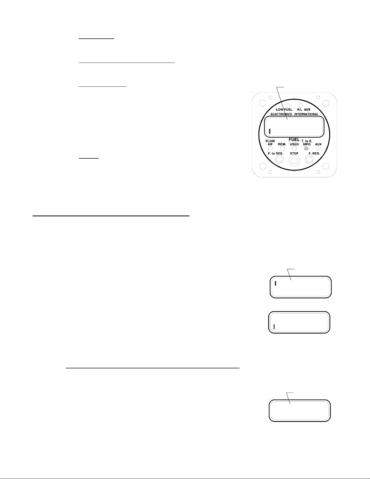
a) Select a Digit - The Right and Left “PRG” buttons move the blinking digit to the right or to the
left.
b) Increase or Decrease a Digits Count - Moving the "STEP Switch" to the right will increase the
blinking digits count and moving it to the left will decrease the blinking digits count.
c)
Change Functions - The display will toggle between the Time
to Empty Alarm limit and the Reoccurring Alarm limit by
pushing the Right "PRG" button with the right digit blinking or
by pushing the Left "PRG" button with the left digit blinking.
The Time to Empty Alarm limit is always displayed with a bar
in the upper left corner of the display and the Reoccurring
Alarm limit is always displayed with a bar in the lower left
corner of the display.
To Exit - To exit the Pilot Programming Settings for the
d)
"T. to E." Display Mode, momentarily push both “PRG”
buttons at the same time. The programmed values will be
stored in memory and no internal batteries or external power
are required to store this information for life.
Blinking Digit
Gal
005
Power-Up Programmable Settings:Power-Up Programmable Settings:
Power-Up Programmable Settings:
Power-Up Programmable Settings:Power-Up Programmable Settings:
The FP-5(L) has nine Power-Up Programmable Settings and the FP-5L has two additional settings. These
programmable settings need to be set only once to configure the instrument to your aircraft, engine and personal
preference. The following settings are available:
1&2. First and Second Full Fuel Levels:
There are two Full Fuel Levels that may be set in the FP-5(L). When adding fuel
to the FP-5(L), the First and Second programmed Full Fuel Levels may be retrieved
automatically. The First Full Fuel Level will be displayed with a bar in the upper left
corner of the display. The Second Full Fuel Level will be displayed with a bar in the
lower left corner of the display.
Blinking Digit
Gal
050
Gal
060
3. K Factor:
The K Factor represents the number of electrical pulses per gallon the FP-5(L) receives from the flow
transducer. Changing the K Factor changes the accuracy of the FP-5(L). Initially, the K Factor should be
set to the value listed for the specific flow transducer. If the flow transducer came from the factory as a package,
the proper K Factor would have been set in the instrument.
Example: Value listed 68,000 (68,000 pulses per gallon measured on the
bench). Set the K Factor on the FP-5(L) for the first three digits
of the K Factor listed (680).
16
Blinking Digit
680
Page 19

The differences between the elbows, fittings, pipe sizes, hoses and routing methods used during installation
and the fuel pressure for your aircraft can, for any fuel flow gauge, cause the flow transducer to output a
different number of electrical pulses per gallon (K Factor) than when it was tested on the bench. To correct
for any errors in the K Factor, keep track of the Actual Fuel Used (fuel required to bring the tanks back to
full) and compare this with the FP-5(L) Fuel Used (Full Tank Level minus Fuel Remaining as displayed on the
FP-5(L)). If your error is less than 3 gallons for a single tank, you should average the error over 3 tanks of
fuel. Use the following formula to correct the K Factor:
(FP-5(L) Fuel Used) x (Current K Factor)
New K Factor = -----------------------------------------------------
Actual Fuel Used
Note: The K Factor can be automatically corrected by using the "Auto Calibrate" Mode (see the Display
Modes and Operation Features section of this manual).
Note: When refueling an aircraft fuel tank, it is not easy to fill the tanks to exactly the same level each time.
Some variables are: 1. How level the wings are during refueling. 2. The affects of any crossover tubes.
3. The ability of the line attendant to fill the tank to the same mark. Also, the shape of the tank and the
dihedral of the wings can aggravate the situation.
Note: K Factor settings below 580 will cause the display resolution to increase above .1 Gal/Hr. when used
with a Display Update Time setting of "UP2." K Factors below 180 will cause the display resolution to
increase above .1 Gal/Hr. when used with a Display Update Time setting of "UP1." The FT-90 Flow Trans-
ducer has a K Factor around 198.
4. Filter:
There are two filters used by the FP-5(L) to remove fluctuation or jump in the fuel
flow readings. Selecting either filter will not affect the accuracy of the FP-5(L). Use
filter “F 1” for most fuel-injected engines. This filter has the fastest response time
(eight times faster than other flow gauges). Use filter “F 2” for most carbureted
engines. This filter has a slightly slower response time than F1 (still faster than other
flow gauges) but will take out any fluctuation or jump you may have seen using the F1
filter.
5. Display Update Time:
The Display Update Time may be set to "UP2" or "UP1." An "UP2" setting
causes the display to update two times per second and a .1 Gal/Hr. resolution can be
maintained for K Factors from 580 to 1999. A "UP1" setting causes the display to
update once per second and a .1 Gal/Hr. resolution can be maintained for K Factors
from 180 to 999. When using the FT-60 Flow Transducer use the "UP2" setting. When
using the FT-90 Flow Transducer use the "UP1" setting if .1 Gal/Hr. resolution is
required, otherwise a "UP2" setting would be preferred.
Blinking Digit
F 1
Blinking Digit
UP2
17
Page 20

6. Fuel Flow at 75% Power (rich mixture) Setting:
This setting calibrates the % Horsepower Display Mode to your engine. This
procedure should be done after your have verified the calibration of the FP-5(L).
Changing the K Factor on the FP-5(L) will change the displayed Fuel Flow and the
displayed % Horsepower.
Fly your aircraft at cruise altitude (or, if necessary, at lower altitude where you can achieve 75% power) with
a rich mixture. Refer to operating charts from your aircraft or engine manufacturer to determine your power
setting. Record the fuel flow displayed on the FP-5(L) at 75% power (rich mixture). For this setting, program the
recorded fuel flow into the FP-5(L). When displaying the Fuel Flow at 75% Power a "r" will be displayed in the
lower left corner of the display.
The FP-5(L) can be set up to display raw horsepower by using the following procedure:
A. Record the Fuel Flow at 75% Power as described above. This value will be designated FF@75%
rich.
B. Program the Fuel Flow Setting in the FP-5(L) using the following formula:
FF@75% rich x 75
Fuel Flow Setting = ---------------------------------------------------------------
HPmax (max horsepower of your engine) x .75
Blinking Digit
Gal/Hr
r 17.0
Note: For most spark ignition piston engines this fuel flow setting will be around 7.0 gallons/hr.
7. GPS Receive Format (FP-5L only):
The GPS Receive Format configures the FP-5L to receive data from a GPS. The data received is used to
calculate fuel to destination, fuel reserve and miles per gallon. If the FP-5L is not receiving data from a GPS, the
display will show " OFF" (the GPS receive wire may be open or connected to the wrong pin on the GPS). If a
signal is present but the baud rate is wrong, the display will show " 'on" (note the tick mark in the upper left corner
of the display). Check the following settings and check that the GPS receive wire is connected to the proper pin
on the GPS. If the baud rate is correct but the ground speed and distance data to waypoint are not available, the
display will show " on" (verify that the GPS is receiving satellites, the GPS output port is configured properly and a
waypoint has been set).
The GPS Receive Format may be set for the following:
" In1" - Receives moving map data at 9600 baud. All panel mount GPS
units we know of output this format. This format enables the FP-5L
GPS output port.
Blinking Digit
In1
" In2" - Receives data from a Northstar unit at 1200 baud. Some newer
Northstar units output moving map data (use " In1").
" In3" - Receives NMEA data from most hand held GPS units at 4800 baud.
18
Page 21

8. GPS Transmit Format (FP-5L only):
The GPS Transmit Format configures the FP-5L to transmit data to a GPS. The data transmitted may or
may not be used by your GPS (check your GPS Operating Manual). The FP-5L GPS output port will only be
enabled when the GPS Receive Format has been set to " In1." For all transmit formats the baud rate is
9600.
The GPS Transmit Format may be set for the following:
" Ot0" - Disables the output port. If your GPS is not going to use the FP-5L
transmitted data, set the GPS Transmit Format to " Ot0."
" Ot1" - Outputs the older Shadin fuel flow data. Works with many older
Arnav, King and newer Garmin GPS units.
" Ot2" - Outputs the Shadin fuel flow sentence. Works with Garmin and many other units.
" Ot3" - Outputs a modified Shadin Fuel/Airdata sentence. Works with many UPS GPS units.
9. Scan Rate:
The Scan Rate (the time the FP-5(L) takes to switch between display modes) can
be set from 0 to 9 seconds. A "0" setting disables the scan feature. When displaying
the Scan Rate "Sn" will be shown in the left of the display.
To program the Power-up Programmable Settings, perform the following steps:
A. Turn the aircraft electrical power off, push both “PRG” buttons, and hold them in.
Blinking Digit
Ot1
Blinking Digit
Sn3
B. Turn the aircraft electrical power on, wait two seconds, then release the “PRG” buttons. At this
point, the far left digit should be blinking and there should be a bar in the upper left corner of the
display. All the green display mode LEDs should be off. If this is not the case, go back to step A.
The 1st Full Fuel Level is being displayed and you are now ready to program the Power-up Programmable Setting that were described above.
a)
Select a Digit - The Right and Left “PRG” buttons move the blinking digit to the right or to the
left.
b) Advance a Digits Count - Moving the Mode Select Switch to the right will increase the blinking
digits count by one or to the left to decrease a blinking digits count by one. After the blinking digit
reaches 9 it will reset to 0.
c) Change Functions - The display will toggle between the Power-up Programmable Settings
described above by pushing the Right "PRG" button with the right digit blinking (advances to the
next function) or by pushing the Left "PRG" button with the left digit blinking (returns to the last
function). For each function the display will appear as described above.
d) To Exit - To exit the Power-up Programming Mode, momentarily push both “PRG” buttons at
the same time. The programmed values will be stored in memory and no internal batteries or
external power are required to store this information for life.
19
Page 22

Specifications and Operating Features
Model:
FP-5-LxxHyy and FP-5L-LxxHyy (Primary Fuel Flow/Pressure Instrument)
Case Dimensions:
2.5" x 2.5" x 3.65" depth, 2 1/4" Bezel.
Weight:
Instrument Only: 11 Oz.
Flow Transducer FT-60 or FT-90: 6 Oz.
Fuel Pressure Transducer PT-100GA: 2 Oz.
Environmental:
Meets TSO C44a/C47
Power Requirements:
7.5 to 35 Volts, 1/10 Amp.
Green Display Mode Indicator LEDs:
The intensity of these LEDs is controlled by the dimming wire. 12 or 24 volts on this wire will dim the LEDs
for night operation.
Red Low Fuel Warning LED:
This LED will blink any time the programmed First or Second Low Fuel limit, Time to Empty Limit or Reoc-
curring Alarm is violated. The Low Fuel Warning LED is always displayed at full intensity and will flash on
power-up.
Red H/L PRESS Warning LED:
This LED will blink any time the factory programmed High or Low Pressure limit is violated. The H/L
PRESS Warning LED is always displayed at full intensity and will flash on power-up.
Digital Display:
LCD (viewable in direct sunlight), with 12 and 24 volt backlight control wires for night operation. Displays
"8888" on power up.
External Warning Control Line:
Grounds when any Red Warning LED is on or blinking. Current should be limited to 2/10 amp.
Accuracy:
Flow: 2% o r better in accordance with TSO C44a.
Pressure: 2% in accordance with TSO.
Resolution:
Fuel Flow: .1 Gal. o r 1 L b . o r 1 L t r .
Fuel Remaining: .1 Gal. up to 99.9 Gal or 1 Lb. or 1 Ltr.
Fuel Used: .1 Gal. up to 99.9 Gal or 1 Lb. or 1 Ltr.
Time to Empty: 1 minute
Fuel Pressure: .2 PSI (with PT-100GA)
20
Page 23

Max Displayed Range (Unit Only):
Fuel Flow: 199.9 Gals/Hr or 162.0 br Gal/Hr or 1199 Lbs/Hr or 749 Ltr/Hr.
Fuel Remaining: 999 Gals. or 811 br Gal. or 1999 Lbs. or 1999 Ltr.
Fuel Used: 999 Gals. or 811 br Gal. or 1999 Lbs. or 1999 Ltr.
Time to Empty: 19 hours 59 minutes
Fuel Pressure: .5 to 199.8 PSI (Readings below .5 PSI will be displayed as 00.0 PSI)
RS-232/422 Input Ports (FP-5L-LxxHyy Only):
Single Line Receive Method: RS-232C or RS-423
Dual Line Receive Method: RS-422 or RS-485 (with 120 ohm external resistor)
Protocol: 1 Start bit, 8 Data bits, 1 Stop bit.
Baud Rate: 1200, 4800, 9600
Receive Format: Moving Map, Northstar or NEMA.
RS-232/422 Output Port (FP-5L-LxxHyy Only):
Transmit Method: RS-232C Single Line.
Protocol: 1 Start bit, 8 Data bits, 1 Stop bit.
Baud Rate: 9600 (Receive Format must be set to Moving Map).
Transmit Format: King KLN88, Garmin, or UPS.
Fuel Flow Transducer, Standard (FT-60):
Range: 0.6 to 70+ GPH
Linearity: 1% over an engines normal operating range.
K Factor: Approx. 68,000
Pressure Drop: 0.5 PSI at 28 GPH
2.0 PSI at 56 GPH
Working Press: 1000 PSI
Min. Burst Press: 4000 PSI
Temp. Range: -65'C to 125'C
Fuel Ports: 1/4" Female NPT
Fuel Flow Transducer, Special (FT-90):
Range: 2 to 125+ GPH
K Factor: Approx. 33,800
Pressure Drop: 0.5 PSI at 63 GPH
2.0 PSI at 127 GPH
Working Press: 1000 PSI
Min. Burst Press: 4000 PSI
Temp. Range: -65'C to 125'C
Fuel Ports: 1/4" Female NPT
Fuel Pressure Transducer (PT-100GA):
Range: 0 to 100 PSI
Over Press: 300 PSI without damage.
Min. Burst Press: 500 PSI
Temp. Range: -40'C to 125'C
Material: 303 Stainless Steel
Press. Port: 1/4" Male NPT
Fuel Flow Transducer, FT-180 (Black Cube):
Range: 2 to 250+ GPH
K Factor: Approx. 22,700
Pressure Drop: 0.5 PSI at 88 GPH
2.0 PSI at 176 GPH
Working Press: 1000 PSI
Min. Burst Press: 4000 PSI
Temp. Range: -65 to 125'C
Fuel Ports: 1/4" Female NPT with #8
Female Flare Fitting
21
 Loading...