

Page 1
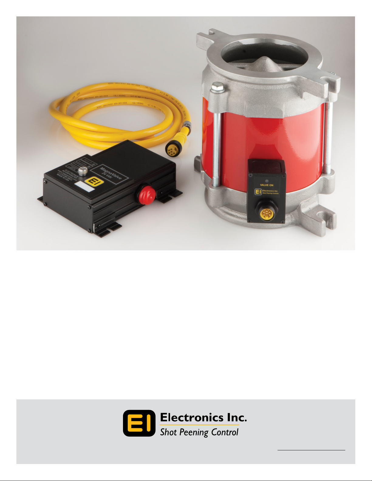
WM 3000-24 MagnaValve®
Instruction Manual
56790 Magnetic Drive, Mishawaka, Indiana 46545 USA • 1-800-832-5653 or (574)256-5001 • www.electronics-inc.com
Rev2/13
Page 2

Table of Contents
Product Overview and Principle of Operation ...........................................................................3
Installation .................................................................................................................................................. 4
Adjustments ..............................................................................................................................................4
Operation - MagnaValve ...................................................................................................................... 4
Operation - Remote Valve Driver ..................................................................................................... 5
Specifications ............................................................................................................................................ 6
Dimensions ................................................................................................................................................ 7
Remote Valve Driver Cable Connection ........................................................................................ 8
AC-24 Controller Cable Connection ...............................................................................................8
Troubleshooting ......................................................................................................................................9
Maintenance ............................................................................................................................................10
Spare Parts List ........................................................................................................................................10
Warranty ....................................................................................................................................................10
Contacting Electronics Inc.................................................................................................................10
Read this manual completely before installing the MagnaValve.
WARNING!
The MagnaValve emits magnetic elds and can be harmful to pacemaker wearers.
2
Page 3

Product Overview and
Principle of Operation
MagnaValve® Description
The MagnaValve® WM 3000-24 is a normally closed valve that regulates the ow
of steel shot or grit in wheel-blast machines for blast cleaning applications. It is a
powerful valve with a ow rate capacity of up to 3,000 lb/min (1,361 kg/min) for
wheels up to 125 hp. The Remote Valve Driver for the MagnaValve comes with a 6-ft
cable for installation in the customer’s electrical panel, making it an ideal valve for
blast machines in high-temperature environments.
The MagnaValve reduces media usage, energy costs, machine downtime, and wear
and tear on equipment.
How It Works
The MagnaValve’s maintenance-free construction includes a rare earth permanent
magnet for normally closed operation and an electromagnet for controlling shot ow
rates. With power applied, the magnetic eld is neutralized and shot is allowed to
ow through the valve. When no power is applied to the MagnaValve, the permanent
magnet stops all ow. If the power is interrupted for any reason, the permanent
magnet securely holds the shot.
The MagnaValve is factory tested and results are supplied upon request.
MagnaValve Controllers for Closed-Loop Operation
For an “automatic” closed-loop operation, an Electronics Inc. AC-24 Controller will
detect the current load on the wheel motor and regulate the ow of media to the
WM 3000-24. The WM 3000-24 MagnaValve, with the AC-24 Controller, provides
reliable, repetitive, and consistent media ow rates for blast cleaning applications.
The MagnaValve system makes it easy to document ow rates and establish or repeat
a good set-up.
AC-24 Controller Data Sheet
http://www.electronics-inc.com/uploads/AC-24Controller(1).pdf
AC-24 Controller Instruction Manual
http://www.electronics-inc.com/data_sheets_and_instruction_manuals_for_wheel_blast_machine_products2.html
3
Page 4

Installation
MagnaValve
The MagnaValve must be mounted in a vertical position with an adequate supply of
media above it.
Remote Valve Driver
The Remote Valve Driver should be mounted in an electrical panel that conforms to
the temperature range of 50˚- 120˚ F (10˚- 49˚ C).
Adjustments
MagnaValve
No adjustments are required or recommended. The valve has been tested at the
factory prior to shipment.
Remote Valve Driver
Adjustments to the Remote Valve Driver can be made from the front of the driver;
however, the factory settings should not be changed. The output signal is 10 Vdc. See
page 5 for additional information on the Remote Valve Driver.
Operation
MagnaValve
Signals used to operate the MagnaValve originate at the AC-24 Controller. There are
three conditions necessary for correct operation.
1) Power. 24 Vdc power must be continuously applied to the valve. The valve
requires 2 Amps for operation and a power supply rated at 50 Va. The voltage
should be 24 ±2 Vdc.
2) Enable Signal. The 24 Vdc Enable Signal is used to activate the valve.
3) Input Signal. The analog 0 -10 Vdc input signal must be above 0.25 Vdc as a
minimum ow command signal.
AC-24 Controller Operation
Please download the AC-24 Instruction Manual
http://www.electronics-inc.com/data_sheets_and_instruction_manuals_for_wheel_blast_machine_products2.html
4
Page 5

Operation
Remote Valve Driver
Valve Driver Panel (behind the cover plate)
The large knurled screw on the front cover of the Remote Valve Driver can be removed to gain
access to the factory adjustments. Please refer all adjustments to qualied personnel.
Diagnostic LEDs*
Valve On. Indicates when power is being sent to the MagnaValve’s electromagnet. When the
LED is on, the valve is on for full capacity ow rate. When the LED is o, the MagnaValve’s
permanent magnet has stopped the media ow. When the LED is blinking, the shot ow is
being regulated.
è
é
Valve Pulse
Rate at which the valve dispenses shot. The Valve Pulse
is factory set to match the best ow characteristics of
the media (cast steel or cut wire). The typical operation
rate is 8 Hertz.
*Diagnostic LEDs
ç
Test Connector
Provides access to
diagnostic voltages.
• 0 - 10 Vdc input
• 24 Vdc “Enable” input
• 6 - 20 Hertz pulse rate
• 0 Vdc common
Vin > 0.25 Vdc. Indicates that an analog signal input greater than 0.25 Vdc has been received.
When this LED is o, no media ow is allowed. The input signal range is 0 -10 Vdc. At 10 Vdc,
the MagnaValve will open to full capacity. The relationship between the 0 -10 Vdc input signal
and actual ow rate is non-linear.
24 Vdc Enable. Indicates that the 24 Vdc Enable Signal has been received. When the LED is
o, the MagnaValve is inhibited and no shot will ow. This feature is provided as an on-o
action so the 0-10 Vdc input signal does not have to be disabled or removed.
24 Vdc Power. Indicates that 24 Vdc is available to operate the electromagnet for media ow.
It should always be available and able to supply 2 Amps.
All four LEDs must be on in order to have media ow.
5
Page 6

Specifcations
MagnaValve
Power +24 Vdc @ 2A (50 VA)
Media Steel Shot and Grit
Weight 32 lb (14.5 kg)
Mode Normally Closed
Temperature Range Valve: 50˚- 230˚ F (10˚-110˚ C)
Signal Input 0 - 10 Vdc
Flow Output 0 - 3,000 lb/min (0 - 1,361 kg/min)*
Display LEDs Valve On
0 - 10 Vdc Command Input Available
24 V Flow Enable
+24 Vdc Power
Cable: 2 Conductor shielded 18 AWG or equivalent.
Connect shield at control only.
* Flow rate based on S230 cast steel shot
Remote Valve Driver
Temperature Range 50˚- 120˚ F (10˚- 49˚ C)
6
Page 7

.91”
.91”
(23 mm)
9.30”
(236 mm)
4.50”
(114 mm)
1.50”
(38 mm)
1.50”
(38 mm)
.56”
(14 mm)
10.00”
(254 mm)
9.00”
(229 mm)
2.87”
(73 mm)
4.29”
(109 mm)
7.13”
(181 mm)
5.00”
(127 mm)
(23 mm)
Dimensions
7.13”
(181 mm)
10.00”
(254 mm)
9.00”
(229 mm)
5.00”
(127 mm)
9.30”
(236 mm)
1.50”
(38 mm)
For stability, the MagnaValve should be located as close as possible (within at least 3 ft / 1 m) to the blast machine wheel.
6.50”
(165 mm)
4.75”
(121 mm)
1.50”
(38 mm)
4.50”
(114 mm)
5.54” (141 mm)
5.00” (127 mm)
4.25”
(108 mm)
(14 mm)
.56”
2.87”
(73 mm)
Panel spacing for the Remote Valve Driver: 5” on cable side, 0.5” on top and bottom.
4.29”
(109 mm)
7
Page 8

Remote Valve Driver Cable Connection
The Remote Valve Driver should be installed in customer’s electrical panel. The 6-pin plug and cable wires connect
to customer’s wiring per the following:
Black Customer Power Supply in control panel - Power bus common 0 Vdc
Red Customer Power Supply in control panel - Power bus hot +24 Vdc
Blue 24 Vdc Enable Input - connect to AC-24 Controller Screw terminal #9, Enable Output
Orange 0-10 Vdc Flow Command Input - connect to AC-24 Controller Screw terminal #8, Flow Command Output
Green MagnaValve power signal - connect to valve driver, Green only
White MagnaValve power signal - connect to valve driver, White only
AC-24 Controller Cable Connection
WM 3000-24
Locate valve within
3 ft/1 m of wheel
feedspout media inlet
Cable #1- Wiring from
the MagnaValve to the
Remote Valve Driver
should be in a private
conduit (no adjacent
motor leads, etc).
Use 18AWG or larger
wire size for runs over
30 ft (10 m). A six-foot
cable and plug are
supplied with the
MagnaValve and only
the green and white
wires need to be
connected. Ignore the
other wires in the cable.
White
Green
Cable #1
24 Vdc
0 Vdc
Enable Input Enable Output
Flow Command
Input
REMOTE
VALVE DRIVER
Valve driver module
located in customer
electrical control panel
Cable #2 - Use only
four wires in Cable #2:
Connect the Red and
Black wires to 24 Vdc
power and the Blue
and Orange wires to
AC-24 Controller.
Do not use White or
Green wires in this
cable.
Red
Black
Blue
Orange
Cable #2
9
8
AC-24 CONTROLLER
Flow Command
Output
19
11
18
24 Vdc
0 Vdc
2
4
7
Shunt
0.05 Ω
5
Remote Setpoint
(if used)
Recorder output
(if used)
Remote Enable
(if used)
100:5 Current Transformer
Pass one loop through
center 0-100 Amps
current transformer.
0-100 Amps Input
0-5 Amps Output
Customer
Power
Supply
}
8
Page 9

Troubleshooting
If all of the LEDs are on but there is no media ow, please check the following:
1) Is the mechanical valve above the MagnaValve fully open?
2) Is media available from the hopper?
3) Is there a blockage above or below the MagnaValve?
4) Is the magnetic eld completely cancelled when the “Valve On” LED is on? Check this by
removing the valve from the machine and applying the proper signals for 100% ow. Did all
of the shot fall from the valve?
If the problem can’t be identied or if you detect a problem with the magnetic eld,
contact Electronics Inc. Please have the following information ready.
1) Number of valves on the machine ___________________________________
2) Controller model _________________________________________________
3) Valve model _____________________________________________________
4) Media type o cast steel o cut wire o grit o other ___________________
5) Media size ______________________________________________________
6) Wheel size (hp) ___________________________________________________
7) Desired wheel amperage (Amps) ____________________________________
8) Cycle time ______________________________________________________
9) Time between cycles ______________________________________________
10) Where is the shut-o valve? o above the MagnaValve o below the MagnaValve
Make note of LED indicators on the MagnaValve:
How do the MagnaValve LED indicators react during the blast cycle?
__________________________________________________________________________
Make note of LED indicators on the AC-24 Controller (if used):
How do the AC-24 Controller LED indicators react during the blast cycle?
__________________________________________________________________________
Does the AC-24 Controller display read “idle amps” at the end of the blast cycle? o yes o no
Electronics Inc.
Telephone: (574) 256-5001 or 1-800-832-5653 (USA and Canada)
Fax: (574) 256-5222
9
Page 10

Maintenance
The MagnaValve has no moving parts and is thereby maintenance free.
Spare Parts List
The MagnaValve has no moving parts to replace.
Warranty
Two-year warranty
Contacting Electronics Inc.
Electronics Inc.
56790 Magnetic Drive
Mishawaka, Indiana 46545 USA
Telephone: (574) 256-5001 or 1-800-832-5653 (USA and Canada)
Fax: (574) 256-5222
Email: sales@electronics-inc.com
Website: www.electronics-inc.com
Electronics Inc. makes no representations or warranties, either expressed
or implied, with respect to the contents of this publication or the products
that it describes, and specically disclaims any implied warranties of
merchantability or tness for any particular purpose. Electronics Inc. reserves
the right to revise this publication and to make changes and improvements to
the products described in this publication without the obligation of Electronics
Inc. to notify any person or organization of such revisions,
changes or improvements.
10
 Loading...