

Page 1
S1004911
Ultimate Engine Analyzer
(US-8A)
Operating and Installation Instructions
OI072491 and II072091
7/20/89
Rev. B: 2/1/93 *
You must read this manual before installing or operating the instrument. This
manual contains warranty and other information that may affect your decision
to install this product and/or the safety of your aircraft.
S/N:
Electronics International Inc. ®
63296 Powell Butte Hwy Bend, OR 97701 (541) 318-6060 Buy-EI.com
Page 2
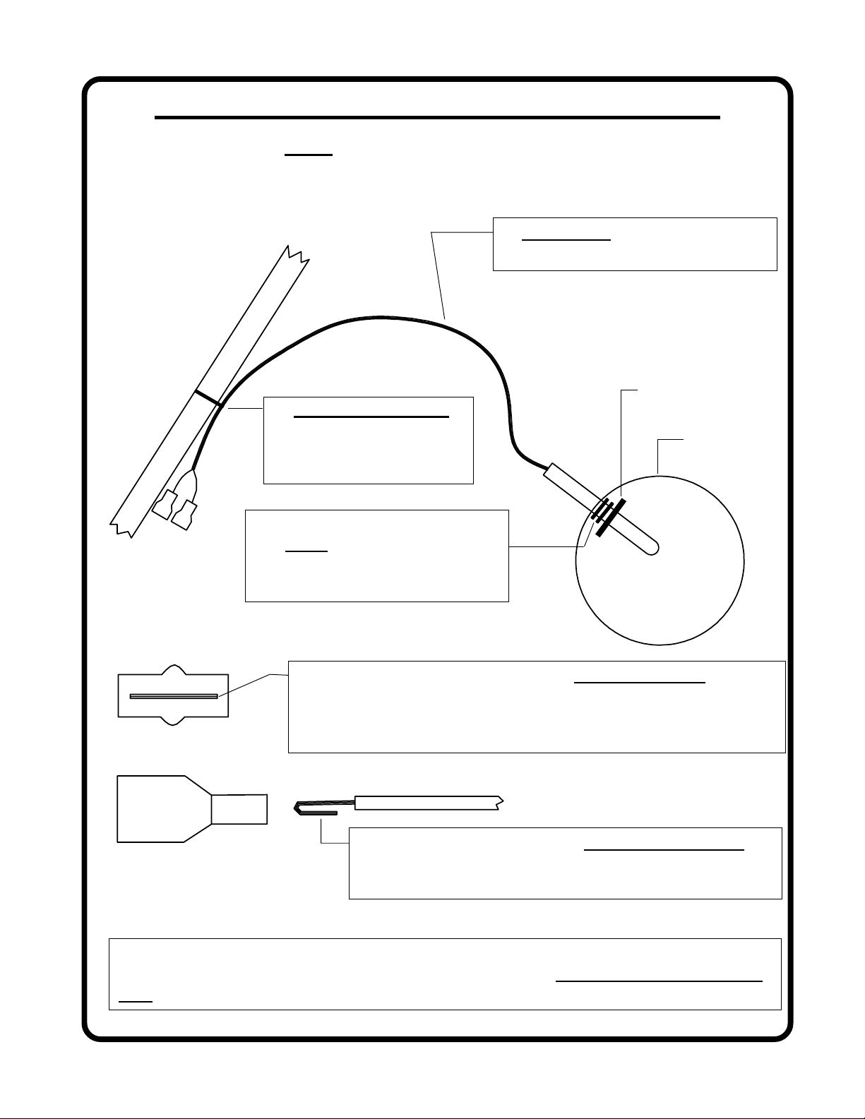
All steps must be read before installing a probe.
F
1. Leave slack in the cable to allow
for engine movement and vibration.
S.S. Washer.
2. Do Not Overtighten.
Over time, tight wire
wraps will cause the wire
to break.
Hose Clamp.
E
Male Conn.
3. Both clip rings must be on
the inside of the hose clamp.
The rubber band is used to hold
the washer on during shipping.
4. The tab inside the male connector must be centered (not
bent up or down) to mate properly. Check each connector
before installation. Two drops of oil on the connector will
protect it from corrosion for many years.
5. If you remove a connector, double over the wire
before installing it into a new connector. Each connector must be double crimped very tightly.
6. If connectors have been disconnected several times the female connector may become
loose. If this happens use a pair of needle nose pliers to retighten the female recep-
tacle then mate the connectors.
Page 3

Important Notice
***** MUST READ *****
If you think it is not important to read this manual, you're wrong! This manual
contains important installation information that may affect the safety of your aircraft, delay your installation or affect the operation of your instrument. You
read this manual prior to installing your instrument. Any deviation from these
installation instructions is the sole responsibility of the installer/pilot and may
render the STC invalid.
Read the Warranty / Agreement. There is information in the Warranty / Agreement that may alter
your decision to install this product. If you do not accept the terms of the Warranty / Agreement, do not
install this product. This product may be returned for a refund. Contact Electronics International inc. for
details.
Check that the instrument make and model marked on the side of the instrument and on the invoice are
correct before starting the installation.
Must
It is possible for any instrument to fail thereby displaying inaccurate high, low or jumpy readings.
Therefore, you must be able to recognize an instrument failure and you must be proficient in operating your
aircraft safely in spite of an instrument failure. If you do not have this knowledge, contact the FAA or a
local flight instructor for training.
The pilot
to operate the aircraft that does not know the operation of this product. Keep the Operating Manual in the
aircraft at all times.
must understand the operation of this product before flying the aircraft. Do not allow anyone
Page 4

Contents
Warranty ---------------------------------------------------------------------------- 2
Operating Information: ----------------------------------------------------------- 3
Introduction ------------------------------------------------------------------------------------- 3
Features ------------------------------------------------------------------------------------------ 3
Programming ------------------------------------------------------------------------------------ 6
Selecting The Proper Limits ------------------------------------------------------------------ 10
Operating The Ultimate Analyzer in Your Aircraft --------------------------------------- 15
Installation Instructions: ---------------------------------------------------------- 18
1. Important Information and Initial Check Out ---------------------------------------------- 18
2. CHT Probe Installation ------------------------------------------------------------------- 18.5
3. EGT Probe Installation ------------------------------------------------------------------- 19
4. TIT Probe Installation -------------------------------------------------------------------- 19
5. Oil Temperature Probe Installation ----------------------------------------------------- 19
6. Carb. Temp. Probe Installation ---------------------------------------------------------- 20
7. OAT Probe Installation -------------------------------------------------------------------- 20
8. Add any Aditional Cables and Mark each Cable ------------------------------------------- 20
9. Route The Circular Connector ------------------------------------------------------------ 21
10. Route Each Extension Cable ------------------------------------------------------------- 21
11. Hook Up Connecting Wires -------------------------------------------------------------- 23
12. Instrument Installation -------------------------------------------------------------------- 23
13. System Ground Test ----------------------------------------------------------------------- 24
Wiring Diagrams ------------------------------------------------------------------ 25
Troubleshooting Suggestions ---------------------------------------------------- 28
Specifications and Operating Features ----------------------------------------- 30
Appendix A - Adding a Channel to the US-8A -------------------------------- 32
Appendix B - US-8A Circular Connectors ------------------------------------- 33
STC Information ------------------------------------------------------------------ 34
1
Page 5

Warranty / Agreement
Electronics International Inc. warrants this instrument and system components to be free from defects in
materials and workmanship for a period of one year from the user invoice date. Electronics International Inc. will repair or replace any item under the terms of this Warranty provided the item is returned
to the factory prepaid.
1. This Warranty shall not apply to any product that has been repaired or altered by any person other
than Electronics International Inc., or that has been subjected to misuse, accident, incorrect wiring,
negligence, improper or unprofessional assembly or improper installation by any person. This warranty
does not cover any reimbursement for any persons time for installation, removal, assembly or repair.
Electronics International retains the right to determine the reason or cause for warranty repair.
2. This warranty does not extend to any machine, vehicle, boat, aircraft or any other device to which the
Electronics International Inc. product may be connected, attached, interconnected or used in conjunction
with in any way.
3. The obligation assumed by Electronics International Inc. under this warranty is limited to repair,
replacement or refund of the product, at the sole discretion of Electronics International Inc.
4. Electronics International Inc. is not liable for expenses incurred by the customer or installer due to
factory updates, modifications, improvements, upgrades, changes, or any other alterations to the product
that may affect the form, fit, function or operation of the product.
5. Personal injury or property damage do to misinterpretation or lack of understanding this product is solely the
pilots responsibility. The pilot must understand the operation of this product before flying the aircraft. Do not
allow anyone to operate the aircraft that does not know the operation of this product. Keep the Operating Manual
in the aircraft at all times.
6. E. I. Inc. is not responsible for shipping charges or damages incurred under this Warranty.
7. No representative is authorized to assume any other liability for Electronics International Inc. in
connection with the sale of Electronics International Inc. products.
8. If you do not agree to and accept the terms of this warranty, you may return the product for a
refund.
This Warranty is made only to the original user. THIS WARRANTY IS IN LIEU OF ALL OTHER
WARRANTIES OR OBLIGATIONS: EXPRESS OR IMPLIED. MANUFACTURER EXPRESSLY
DISCLAIMS ALL IMPLIED WARRANTIES OF MERCHANTABILITY OR FITNESS FOR A
PARTICULAR PURPOSE. PURCHASER AGREES THAT IN NO EVENT SHALL MANUFACTURER BE LIABLE FOR SPECIAL, INCIDENTAL OR CONSEQUENTIAL DAMAGES, INCLUDING LOST PROFITS OR LOSS OF USE OR OTHER ECONOMIC LOSS. EXCEPT AS
EXPRESSLY PROVIDED HEREIN, MANUFACTURER DISCLAIMS ALL OTHER LIABILITY
TO PURCHASER OR ANY OTHER PERSON IN CONNECTION WITH THE USE OR PERFORMANCE OF MANUFACTURERS PRODUCTS, INCLUDING SPECIFICALLY LIABILITY IN
TORT.
2
Page 6
US-8A
S1004911
OPERATING INFORMATION
OI 072491
Rev. A 10/04/91
Introduction
The Ultimate Analyzer is one of the most sophisticated diagnostic tools you can buy for your aircraft. You can
learn the basic operation of this unit in the first few minutes of hands-on operation. Although the Ultimate
Analyzer is simple to operate, its capabilities are numerous. This manual covers the operation of the Ultimate
Analyzer in the following four sections:
1. Features - Describes the operating features of the Ultimate Analyzer.
2. Programming - Describes how to program the Ultimate Analyzer.
3. Selecting the Proper Limits - Describes how to select the limits that should be programmed into the
Ultimate Analyzer.
4. Operating the Ultimate Analyzer in Your Aircraft - Describes how to operate the Ultimate Analyzer
for the different phases of a flight (taxi, run-up, takeoff, climb, cruise and descent).
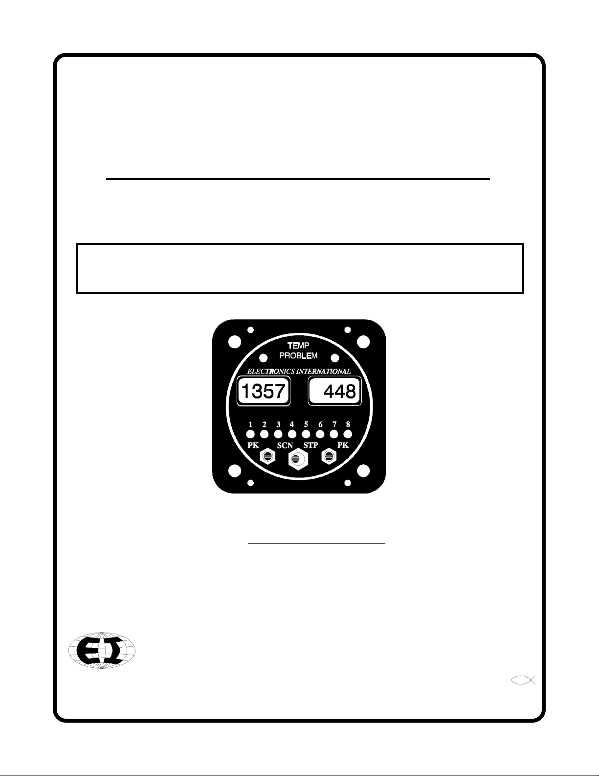
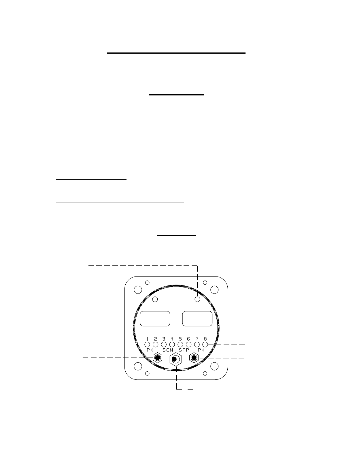
Temperature Problem
Warning Lights
Left Display Window
Left Peak
Locate Switch
Features
Temp Prob
1473
482
Mode Selector Switch:
Left Position = Scan Mode
Center Position = Manual Mode
Right Position = Step
3
Right Display Window
Channel
Indicators (8ea.)
Right Peak
Locate Switch
Page 7

Operating Information
1. Multi-Function Capability:
The Ultimate Analyzer has up to 16-channel capability, 8 for each of the displays. For a 6-cylinder single
engine aircraft, the first 6 channels on the left display should be used for EGT and the first 6 channels on the
right display should be used for CHT. For a twin-engine aircraft the first 6 channels should be left EGT and
right EGT. These channels are designated as analyzer channels. The Peak Locate, Hottest Cylinder Indicator and Differential Warning features are only functional on the analyzer channels. The number of analyzer
channels is independently programmable from 1 to 8 for each display. The High-Temp and Low-Temp
features are functional on all channels and may be used to measure any temperature (TIT, Oil, EGT, CHT,
OAT, Carb, Induction Air, Cabin Air, Cowling Air, Intercooler, Water, etc.).
2. Mode Select Switch:
A) Manual Mode - With the Mode Select Switch in the center position, the Ultimate Analyzer will display
the temperatures on the channel designated by the green Channel Indicators. No other channels are being
monitored at this time. In the Manual Mode the Shock-Cooling and High-Temp warning features are enabled
for only the channel displayed. The Low-Temp and Differential warning features are disabled so you may
operate the aircraft at idle and taxi without getting warning lights.
Features
B) Step Position - Each time the Mode Select Switch is pressed to the right, the Ultimate Analyzer will
advance to the next channel. When this switch is released, it will return to the center position (Manual
Mode). The Ultimate Analyzer can be programmed from the front panel to step through 2 to 8 channels.
C) Scan Mode - In the Scan Mode, the Ultimate Analyzer will scan through the channels, automatically
analyzing your engine. When the unit is first placed into the Scan Mode, it will switch to Channel One to
start its scan. This is done to establish a reference for the automatic engine analysis features.
In the Scan Mode the High-Limits, Low-Limits, and Differential warning features are enabled. The ShockCooling feature is disabled (Shock-Cooling is only a problem during descents).
The Ultimate Analyzer may be placed in the Scan Mode during run up, takeoff, climb or cruise, as long as
the engine temperatures are increasing or stable and above the programmed lower limits. This unique
operating characteristic allows the Ultimate Analyzer to stand watch over your engine during most phases of
a flight. But if the engine temperatures are decreasing (which would occur on a descent) or low (which
would occur at idle, the Ultimate Analyzer should be placed into the Manual Mode of operation to eliminate
any false Low or Differential Condition problems it may find and to enable the automatic Shock-Cooling
detection feature.
3. Peak Locate Switch:
There are two Peak Locate Switches, one for the left display and one for the right. The Peak Locate feature
may be used in the Manual or Scan Mode of operation. Its purpose is to eliminate all of the mental calcula-
4
Page 8

tions and time to find the hottest cylinder. This can be a real asset in leaning or locating a possible problem.
When used for EGT leaning, it should be noted that the leanest cylinder is not always the hottest; but it is the
cylinder you want to start your leaning process on. Precision leaning will then be done to 1'F and the
Cylinder will be verified. Leaning will be covered later in this manual.
A) Manual Mode - To find the hottest analyzer cylinder in the Manual Mode, press the Peak button. The
Ultimate Analyzer will automatically switch to Channel One and start a fast scan (one second per channel).
It will only scan through the analyzer channels and jump to the hottest channel when done.
B) Scan Mode - You may also use the Peak Locate feature in the Scan Mode. The Ultimate Analyzer will
operate the same as in the Manual Mode. After it has found the hottest analyzer channel it will continue
scanning at the programmed scan rate.
4. Hottest Cylinder Indicator:
In the Scan Mode only, the Ultimate Analyzer will light a bar high in the left hand corner of the display any
time it is displaying the hottest analyzer cylinder. This feature allows you to determine if the leanest cylinder
has changed. If this happens, you may need to readjust your mixture.
FeaturesOperating Information
Leanest
5. Temp Prob Warning Lights (Automatic Engine Analysis):
A) High-Temp Problem (Scan and Manual Modes) - If the temperature being displayed exceeds the
programmed limit, the Temp Prob warning light over the appropriate display will come on. Also, there
will be a bar high in the left hand corner of the display. If you are in the scan mode, the scan will stop on the
problem channel.
B) Low-Temp Problem (Scan Mode only) - If the temperature being displayed is less than the programmed
Low Limit, the Temp Prob warning light over the appropriate display will come on. Also, there will be a
bar low in the left hand corner of the display and the scan will stop on the problem channel.
C) Differential Temp Problem (Scan Mode only) - Any time the temperature difference between the
hottest and coldest channel exceeds the programmed differential limit the Temp Prob warning light over
the appropriate display will come on. Also, the high and low bar in the left hand corner of the display will
alternately blink and the Ultimate Analyzer will stop on the coldest cylinder. In this case, the problem may
be the coldest cylinder or it may be the hottest cylinder. By comparing temperatures with adjacent cylinders
the problem cylinder will become apparent. To quickly find the hottest cylinder, press the PK button on
the front panel.
D) Shock-Cooling Temp Problem (Manual Mode only) - Any time you are on a channel on which the High
Limit has been programmed between 300F and 600F (this indicates a CHT channel) and the temperature
being monitored is between 300F and 600F (this is the critical range of cylinder head temperatures) and the
temperature is decreasing faster than the programmed limit, the appropriate Temp Prob warning light will
blink.
5
Page 9

Operating Information
NOTE: The Ultimate Analyzer will stop on the first channel on which it finds a problem and light the
appropriate Temp Prob warning light. If the problem corrects itself, the Temp Prob warning light will go
out and the Ultimate Analyzer will continue its scan.
6. Back Light and Green Channel Indicator Intensity:
The Ultimate Analyzer comes with 12 and 24 volt digital display back light control lines. The digital display
should be backlit all the time. This will allow it to be easily viewed in dim light. The digital display is best
viewed in high ambient light or direct sunlight.
Also provided is a Green Channel Indicator Intensity Control Line. If this line is connected to your Panel
Light Rheostat, the Green Channel Indicators intensity can be controlled for night operation. As the Panel
Light Rheostat is turned up the Green Channel Indicators will dim. If you find the Green Channel Indicators
to be too bright during daytime operation, turn the Panel Light Rheostat up slightly to control the intensity of
the Green Channel Indicators to suit your requirements.
Features
Programming
Although programming may be new to some of you, programming the Ultimate Analyzer is simple. After a
few tries, you should have the hang of it. No matter which buttons you push or limits you set you cannot hurt
the Ultimate Analyzer and any limit can be reset.
Your objective is to set the limits on the Ultimate Analyzer just outside the normal operating temperatures for
each measured parameter (see Selecting the Proper Limits section of this manual). The 36 programmable
limits allow you to characterize the Ultimate Analyzer to your engine. That means trend analysis and problem detection is done automatically every 16 seconds and you are alerted as soon as a problem starts to occur
(i.e., if an engine temperature starts to drift high or low from its normal operating temperature range it will be
detected by a High, Low or Differential limit). This is a far better method of trend analysis than pouring over
pages of data every six months.
The golden rule for setting the limits on the Ultimate Analyzer is No Red Light During Take-Off, Climb or
Cruise. The following sections will describe how to program the Ultimate Analyzer.
1. Manual Programming Mode:
There are two programming modes: Manual and Scan. In the Manual Mode you can program the High
Limits, Low Limits, Differential Limits and Shock-Cooling Limits for both the left and right displays.
Before setting your limits it may be helpful to read the Selecting the Proper Limits section of this manual
to get an idea where the limit should be set.
6
Page 10
Operating Information
To enter the Manual Programming Mode, select the channel you would like to program using the Stp
position on the Mode Selector Switch. Then with the Mode Selector Switch in the center position, push both
Pk buttons at the same time. This will put you in the Manual Programming Mode displaying the High
Limit for the channel you selected.
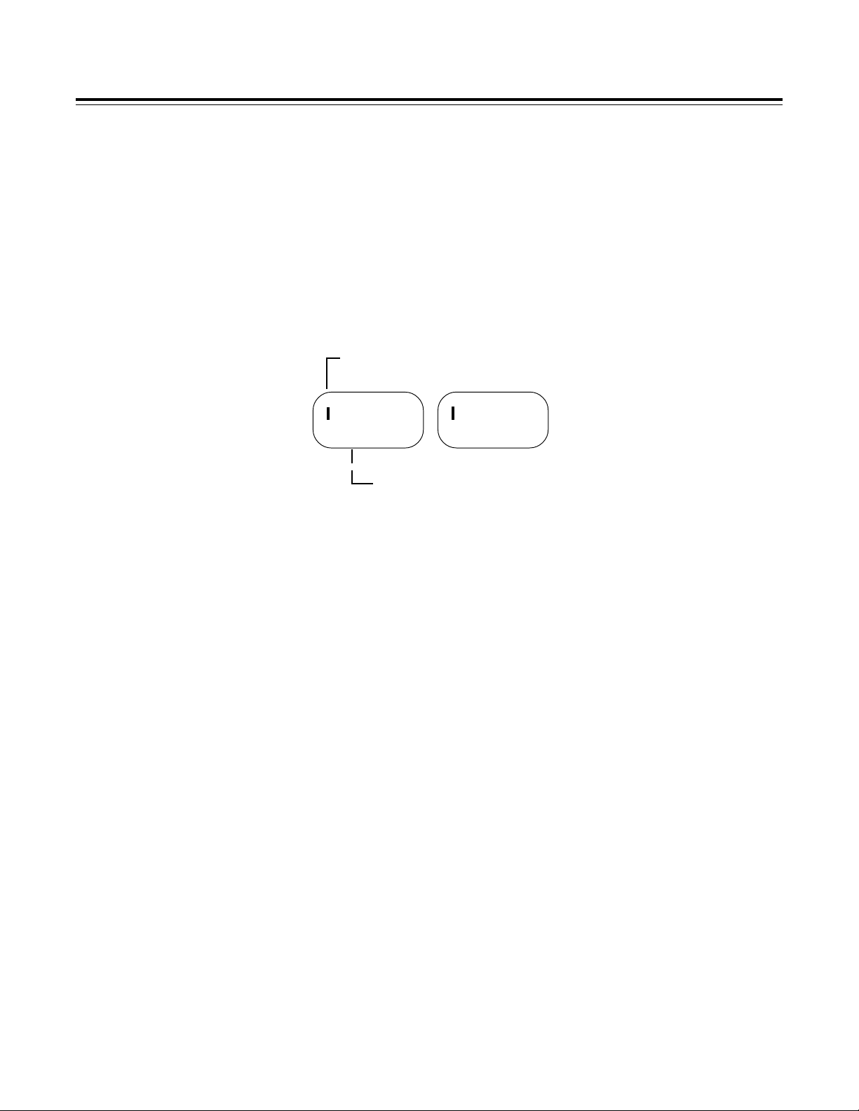
A) Programming a High Limit - There will be a bar in the upper far left corner of the left and right Display
Windows. This high bar indicates you are programming the High Limit. The digit blinking is the only digit
you can program at this time.
High
Bar
Programming
1650
Blinking Digit
1) Select a Digit - The left and right Peak Locate Switches can be used to select the desired digit you
would like to program. Push the right button to select the next digit to the right of the one currently
blinking. Push the left button to select the next digit to the left of the one currently blinking. In this
same manner you can select a digit in the left or right window.
2) Advance a Digits Count - Use the Step Position on the Mode Selector Switch to advance the
blinking digit to the desired limit you would like. When the digit is advanced past 9 (19 for the far left
digit) it will reset to 0. Programming all digits to 0000 will disable the High Limit.
3) Changing Functions - If you are done programming the High Limits for this channel and would
like to program the Low limits, place the Mode Selector Switch in the Scan position. In this manner the
Mode Selector Switch will call up the different functions in the following sequence:
High Limit (set on each channel).
Low Limit (set on each channel).
Differential Limit (set once, shows up on all channels).
1650
Shock-Cooling Limit (set once, shows up on all channels).
4) Leaving the Programming Mode - You may leave the programming mode at any time by pushing
both Peak Buttons at the same time. When this is done, the programmed information is stored in an
EEPROM memory for life, unless you program in new limits. The Ultimate Analyzer does not use any
internal batteries and the information will not be lost if the unit is disconnected from power or removed
from the aircraft.
7
Page 11

ProgrammingOperating Information
B) Programming the Low Limit - If you have selected the Low Limit to be programmed there will be a bar
low in the far left hand corner of the left and right Display Windows. This bar indicates you are programming the Low Limit. The Low Limit may be programmed as shown in steps A-1 and A-2.
To move from programming the Low Limit to programming the Differential Limit, place the Mode Selector
Switch in the Scn position once again. If the Differential limits and Shock-Cooling limits have already
been set, you may want to leave the programming mode at this time (see step A-4). Differential and ShockCooling Limits will show up on each channel even though they only need to be programmed one time.
C) Programming the Differential Limit - There will be NO bars in the far left hand corner of the left and
right Display Windows. This indicates you are programming the Differential Limit. The Differential Limit
sets the maximum allowed difference between the hottest cylinder and the coolest cylinder for the analyzer
channels only. Analyzer channels would be EGTs or CHTs and always start with channel one. There is
only one Differential Limit for each Display Window. This limit can be set on any channel but only needs to
be set once. The Differential Limit may be programmed as shown in steps A-1 and A-2.
To program the Shock-Cooling Limit, place the Mode Selector Switch in the Scan position once again.
D) Programming the Shock-Cooling Limit - The Shock-Cooling limit will be preceded by an Sc in the
left and right Display Windows. The limit is displayed in seconds per one degree change. The ShockCooling Limit may be programmed as shown in steps A-1 and A-2.
Sc3
Blinking Digit
To program the High Limit, place the Mode Selector Switch in the Scan position once again and go to step A.
Every time you go to the Scan position you will be selecting the programmable limits as follows:
High Limit (set on each channel).
Low Limit (set on each channel).
Differential Limit (set once, shows up on all channels).
Shock-Cooling Limit (set once, shows up on all channels).
Sc3
To leave the programming mode, see step A-4.
8
Page 12

ProgrammingOperating Information
2. Scan Programming Mode:
There are two programming modes: Manual and Scan. In the Scan Mode you can program the following
functions in the sequence listed below:
Scan Rate.
Last Channel to be scanned.
Analyzer Channels (6 EGTs, 6 CHTs, etc).
To enter the Scan Programming Mode, place the Mode Selector Switch in the Scan position and push both
Peak buttons at the same time. It does not matter which channel is being displayed when you do this.
A) Programming the Scan Rate - In the left display will be the letters Scn, indicating you are programming the Scan Rate. In the right display will be the Scan Rate displayed in seconds. This number indicates
the time the Ultimate Analyzer will display a channel before stepping to the next channel. The Scan Rate
may be programmed from 2 to 9 seconds per channel by using the Stp Position on the Mode Selector
Switch.
Scn 002
To program the Last Channel to be scanned, place the Mode Selector Switch in the Scn Position once
again.
B) Programming the Last Channel - In the left display will be the letters Ch, indicating you are programming the Last Channel to be used. In the right display will be the last channel the Ultimate Analyzer will
display before resetting to channel one. The Last Channel may be set by using the Step Position on the Mode
Selector Switch.
Ch
To program the Analyzer Channels, place the Mode Selector Switch in the Scan Position once again.
C) Programming the Analyzer Channels - In the left and right display will be 1-?, indicating you are
programming the Analyzer Channels. The "?" will be a number between 1 and 8 and is programmable. If
you have a 6-cylinder engine and have the left display channels 1 through 6 connected to EGTs and the right
display channels 1 through 6 connected to CHTs, you would program the left and right display for 1-6 (a
008
9
Page 13

Operating Information
4-cylinder engine would be programmed for 1-4). This would set up the first six channels to be analyzed
against the Differential Limit and these channels are the only ones looked at when the Peak Button is pressed.
Channels 7 and 8 may be used for any other temperature measurement without interfering with the Differential or Peak Locate features.
Selecting the Proper Limits
1-6
Blinking Digit
To program the Analyzer Channels use the Step position on the Mode Selector Switch to advance the count.
The Peak Buttons may be used to select the left or right digit. To leave the programming mode, press both
Peak Buttons at the same time.
1-6
Selecting the Proper Limits
Your objective is to set the limits on the Ultimate Analyzer just outside the normal operating temperatures for
each measured parameter. The 36 programmable limits allow you to personalize the Ultimate Analyzer to your
engine. That means trend analysis and problem detection is done automatically every 16 seconds and you are
alerted as soon as a problem starts to occur (i.e., if an engine temperature starts to drift high or low from its
normal operating temperature range it will be detected by a High, Low or Differential limit).
The golden rule for setting the limits on the Ultimate Analyzer is No Red Light During Take-Off, Climb or
Cruise. Some General Limits that provide a good starting point for most aircraft are given below:
EGT High Limits ------ -------- 1550F
EGT Lower Limits ------------ 1100F
TIT High Limit ----------------- 1650F
TIT Lower Limit --------------- 1100F
CHT High Limits -------------- 430F
CHT Lower Limits ------------ 150F
Oil High Limit ----------------- 220F
Oil Lower Limit ---------------- 50F
OAT High and Low Limit --- 000 (Limits disabled)
Carb Temp High Limit -------- 150F
Carb Temp Lower Limit ------ 37F
10
Page 14

Selecting the Proper LimitsOperating Information
These limits are only a starting point. More specific information on how to select the proper temperature limits
for your engine is provided below.
1. EGTs:
The Exhaust Gas Temperatures are directly related to your engines ability to produce power. If any cylinder
has a problem producing power (fouled plug, burned or stuck valve, broken ring, intake leak, plugged
injector, timing problem, bad mag, etc.) the EGTs for that cylinder will be abnormally high or low depending on the problem. Each cylinder on your engine operates differently and has a normal operating temperature of its own. The Ultimate Analyzer is capable of being programmed to match each cylinder on your
engine. When selecting the following limits, it is assumed your engine currently does not have a problem
and is operating properly.
A) Selecting the High EGT Limits: At 75% power, lean your engine to peak EGT. Record the EGT
readings for each cylinder. Program the High Limit for each cylinder 40F above the recorded readings for
that cylinder. This is only a recommended limit. As you get to know your engines normal operating
temperatures you may want to adjust these limits accordingly.
B) Selecting the Lower EGT Limits: Set your aircraft up in a normal low cruise power condition. Adjust
the mixture full rich and wait for the EGTs to stabilize. Once the EGTs have stabilized, record the EGT
readings for each cylinder. Program the Lower Limit for each cylinder 40F below the recorded readings for
that cylinder. This is only a recommended limit. As you get to know your engines normal operating
temperatures you may want to adjust these limits accordingly.
C) Selecting the EGT Differential Limit: Your engines EGTs will vary for different power, altitude and
mixture settings. To further enhance the Ultimate Analyzers ability to detect a problem, set your aircraft up
in a normal cruise power condition. Lean your engine and wait for the EGT temperatures to stabilize.
Record the EGTs for each cylinder. Set the Differential Limit for 40F higher than the difference between
the hottest and coldest EGT readings (i.e., Hottest EGT - Coldest EGT + 40F = Setting). This is only a
recommended limit. As you get to know your engines normal operating temperatures you may want to
adjust this limit accordingly.
2. TIT:
Running your engine with turbine inlet temperatures (TIT) above 1650F can cause hairline thermal stress
cracks in the turbine housing. Also, it can cause detonation and preignition, which will lead to burned
valves, bent valve stems, broken rings and cracked exhaust systems. Controlling your TIT temperatures is
essential for turbo-charged aircraft.
The Ultimate Analyzer will continuously monitor your TIT in the scan mode. If the TIT exceeds 1650F, the
Ultimate Analyzer will stop and light a bright red warning light over the display, immediately alerting the
11
Page 15

Operating Information
pilot of an over-temperature condition. This is an important feature for turbo-charged aircraft since turbine
inlet temperatures can easily creep above limit after a change in power or mixture settings.
Another advantage of the Ultimate Analyzer over conventional gauges is its extreme accuracy and linearity.
This assures you of accurate TIT readings.
Turbine housing life is also affected by sudden changes in temperature. Thermal shock can occur during
abrupt changes in the mixture or power settings. Make gentle changes in the mixture and power settings
when transitioning from a higher TIT to a lower temperature. The Ultimate Analyzers 1F resolution will
help in assuring that the proper transitioning of the TIT is taking place.
A) Selecting the High TIT Limit: At 75% power, lean your engine to peak TIT. Allow the TIT
temperature to stabilize. Set your High TIT Limit for 40F above this temperature. Do not exceed the
maximum limit allowed for your aircraft. For most aircraft this limit will be 1650F.
B) Selecting the Lower TIT Limit: Set your aircraft up in a normal low cruise power condition.
Adjust the mixture full rich and wait for the TIT to stabilize. Program the Lower TIT Limit 40F below
this temperature.
Selecting the Proper Limits
3. CHTs:
The Ultimate Analyzer helps you protect your engine against the threat of excessive heat. Most general
aviation aircraft take the CHT off the hottest cylinder determined by extensive flight tests. Minimum inflight CHT should be 150F, and maximum in most direct drive normally aspirated Avco Lycoming engines
is 500F. Some of the higher powered, more complex engines have a limit of 475F. Although these are
minimum and maximum limits, the pilot should operate the engine at more reasonable temperatures in order
to achieve the expected overhaul life of the powerplant. It would be normal during all-year operations in
climb and cruise to see head temperatures in the range of 350F to 435F.
Sudden cooling of the CHT (known as Shock-Cooling) is a problem that is common with aircraft engines.
This is caused by fast descents with little or no power and rich mixtures. This may result in bent pushrods
due to exhaust valves sticking, burned valves, spark plug fouling, broken piston rings, cracked cylinders at
the spark plug and valve ports and warped exhaust valves. To avoid these problems, do not allow the CHT to
cool more rapidly than 1F every 3 seconds during in-flight operation. The Ultimate Analyzer will automatically detect a Shock-Cooling condition in the normal mode of operation for the cylinder being displayed.
When it detects a CHT descending too rapidly the red light over the CHT display will blink.
During climbs, the cylinder head temperatures will rise rapidly until the heat absorbed by the combustion
walls is dissipated out the engines cooling fins. At this point, the CHT will stabilize. Any change in
throttle, mixture, cowl, OAT or airspeed will affect the CHT and the rate at which it will change. Since rate
and trend information can be interpreted easily on the Ultimate Analyzers digital display, changing any one
of these parameters to stabilize, slow or reduce the CHT is possible with almost immediate results.
12
Page 16

Selecting the Proper LimitsOperating Information
The Cylinder Head Temperatures are related to your engines ability to produce power. If any cylinder has a
problem producing power (fouled plug, burned or stuck valve, broken ring, intake leak, plugged injector,
timing problem, bad mag, etc.) the CHT for that cylinder will be abnormally high or low depending on the
extent of the problem. Each cylinder on your engine operates differently and has a normal operating temperature of its own. The Ultimate Analyzer is capable of being programmed to match each cylinder on your
engine. When selecting the following limits, it is assumed your engine currently does not have a problem
and is operating properly.
A) Selecting the High CHT Limits: On a hot day with your engine set to 75% power, lean your
engine to peak EGT. Record the CHT readings for each cylinder with the cowl flaps closed. Program
the High Limit for each cylinder 40F above the recorded reading for that cylinder.
Some aircraft reach the highest CHT temperatures during a long full throttle climb. If this is the case for
your aircraft, record the highest CHT readings for each cylinder during a long climb. Program the High
Limit for each cylinder 40F above the recorded reading for that cylinder.
This High CHT Limit should not be set higher than the maximum limit allowed for your aircraft.
B) Selecting the Lower CHT Limits: The CHT Low Limits should be set to 150F. Operating your
aircraft with CHTs below 150F is not recommended. The large difference between the combustion
temperatures and low CHT temperatures can cause engine damage. Setting the CHTs to this low limit
allows you to place the Ultimate Analyzer in the Scan Mode during take-off without getting any warning lights. That way the Ultimate Analyzer can start analyzing your engine during the take-off roll.
C) Selecting the Shock-Cooling Limit: Lycoming recommends your CHTs do not decrease more
than 1F in 3 seconds. It has been E.I.s experience this is a good number. Set your Shock-Cooling
Rate to 3 seconds for a 1F change.
4. Oil Temperature:
As the oil passes through the engine, it is heated. It then passes through the oil cooler and reaches a stable
temperature, depending on internal engine temperatures, oil flow (pressure, etc.) and oil cooler efficiency
(airspeed, etc.). A change in any of these parameters will cause the oil temperature to increase or decrease.
With the 1F resolution of the Ultimate Analyzer, oil temperature changes can be detected at a glance. This
allows the pilot to diagnose many problems that may never be noticed with a less sensitive gauge. Also, with
the 1F resolution of the Ultimate Analyzer some of our customers are attempting to detect excessive wear in
the engine bearings.
Maintaining your oil temperatures within operating limits is essential. If the oil exceeds its maximum
operating temperature or if it is operated at excessively high temperatures for a long period of time, the oil
will break down and it will not possess the necessary lubricating properties to protect your engine. The
formula for long engine life is to change your oil at regular intervals and watch your oil temperatures with an
accurate gauge that can give you rate and trend information at a glance.
13
Page 17

Operating Information
A) Selecting the High Oil Limit: On a hot day with your engine set at 75% power, lean your engine
to peak EGT. Record the Oil Temperature reading with the cowl flaps closed. Program the High Limit
for 20F above the recorded reading.
Some aircraft reach the highest Oil Temperature during a long full throttle climb. If this is the case for
your aircraft, record the highest Oil Temperature reading during a long climb. Program the High Limit
for 20F above the recorded reading.
This Oil Temperature Limit should not be set higher than the maximum limit allowed for your aircraft.
B) Selecting the Lower Oil Limit: At cold temperatures the viscosity of oil increases. Although
synthetic oils will operate at relatively cold temperatures, most oils will not flow well below 50F. Set
the Lower Oil Limit to the minimum allowed operating temperature limit for your aircraft.
Selecting the Proper Limits
5. Outside Air Temperature:
The Ultimate Analyzer has two features that make it a valuable tool when measuring outside air temperatures. The first of these features is its superior accuracy and linearity over conventional gauges. Outside air
temperatures have a big affect on your aircrafts ability to lift and on engine horsepower. Accurate OAT
readings are essential if you are looking for maximum performance from your aircraft.
The second valuable feature is the Ultimate Analyzers ability to detect small temperature changes (1F).
This gives the pilot rate and trend information (in what direction and how fast the temperatures are changing)
at a glance. This is valuable for detecting changing atmospheric conditions and avoiding thunderstorms and
icing conditions. It can also help in warm weather to find cooler flying conditions.
Selecting the Higher and Lower OAT limits: If the Higher or Lower OAT Limits are exceeded, the scan
will stop and the appropriate Temp Prob light will come on. For this reason you may want to disable the
Higher and Lower OAT Limits (program them for 000).
6. Carburetor Temperature:
Venturi affect and atomization of fuel can cause temperatures in the carburetor to drop 25F or more. When
the atmospheric conditions are right, this temperature drop will cause icing in the carburetor. As icing starts
to form, the Ultimate Analyzer will display a temperature near 32F. To avoid carburetor icing, apply partial
carburetor heat to bring the carb temp between 39F and 49F. Outside air temperatures below 10F will not
cause carb icing due to the lack of moisture in the air.
A) Selecting the High Carb Temp Limit: The High Carb Temp Limit can be used as a fire detector or
detonation deterrent. If the Carb Temp exceeds 150F for many aircraft the engine can detonate at high
throttle settings.
14
Page 18

Operating Information
It is not uncommon for an aircraft engine to backfire on start. This is especially true when the battery is
low. If this happens and a fire starts in the carburetor, it can cause extensive damage before the problem
is noticed. The Ultimate Analyzer can detect this problem almost immediately.
Set the High Carb Temp Limit for 150F. This is only a recommended limit. As you get to know your
engines normal operating temperatures you may want to adjust this limit accordingly.
B) Selecting the Lower Carb Temp Limit: You may want to set the Lower Carb Temp Limit for
37F. This is just above the temperature where ice will form. There is, however, a disadvantage to
setting the Low Limit for 37F. If you fly in very cold weather where ice cannot form, the Ultimate
Analyzer will show a Temp Prob and the automatic scan will stop until the Carb Temp is increased
above 37F. If this is the case, you may want to use partial carb heat or disable the Lower Carb Temp
Limit. Setting a limit to 0000 disables that limit.
Operating the Ultimate Analyzer in Your Aircraft
Operating the Ultimate Analyzer in Your Aircraft
1. Taxi:
During taxi most of your engine temperatures will be below the Lower Temperature Limits. Therefore, to
avoid any red Temp Prob lights, operate the Ultimate Analyzer in the Manual Mode. In the Manual
Operating Mode the Lower and Differential Limits are disabled.
2. Run Up:
During run up you may want to look at each of your engine temperatures by stepping the Ultimate Analyzer
through the channels manually. If you want the Ultimate Analyzer to diagnose your engine automatically,
place the Ultimate Analyzer in the Scan Operating Mode. A situation you may encounter by scanning during
run up is that some of the engine temperatures (such as EGTs) may not exceed their Lower Temperature
Limits. If this is the case, you may want to check your engine using the Manual Mode or program the Lower
Temperature Limits to accommodate scanning at run up.
3. Takeoff:
Place the Ultimate Analyzer in the Scan Operating Mode during takeoff. For the first few seconds of the
takeoff roll you may get a red Temp Prob light until the engine temperatures exceed their Lower Temperature Limits. The Ultimate Analyzer will automatically diagnose your engine during takeoff. A red Temp
Prob light will alert you if the Ultimate Analyzer detects a problem during takeoff.
15
Page 19

Operating Information
For the Ultimate Analyzer to diagnose problems it is important the limits be set properly. The golden rule for
setting the limits on the Ultimate Analyzer is
engine is operating properly and youre getting a red light, see Selecting the Proper Limits section of this
manual.
Operating the Ultimate Analyzer in Your Aircraft
No Red Light During Take-Off, Climb or Cruise. If your
4. Climb:
Leave the Ultimate Analyzer in the scan operating mode during the entire climb. The Ultimate Analyzer will
automatically diagnose your engine during the climb. A red Temp Prob light will alert you if the Ultimate
Analyzer detects a problem. One situation that may occur on non-turbo charged aircraft during a climb is a
low EGT warning. As the aircraft climbs the air gets thinner and the engine will run richer. When this
happens the EGT temperatures will drop and may violate the Lower EGT Limit. Many Ultimate Analyzer
pilots look for this warning to enable them to properly lean during the climb. If you use this method,
allow the EGT temperatures to exceed 1300F for throttle settings above 75% power. Refer to the engine
and aircraft operator's manual for proper leaning information for your aircraft.
do not
5. Cruise:
In cruise you will want to lean your engine. A rich running engine wastes fuel needlessly and tends to run on
the rough side, thereby creating vibration, which causes deterioration of engine accessories and engine
mounts. Also, proper leaning at cruise and during descent means less spark plug fouling, longer life for the
plugs, reduced maintenance costs and a considerable fuel savings. Furthermore, good leaning techniques
result in cleaner combustion chambers with fewer lead salt deposits on the pistons and exhaust valves. Under
certain conditions, these deposits invite preignition and higher maintenance costs. Proper leaning at cruise
during cool or cold weather aids in raising engine and oil temperatures to desirable minimums in order to
evaporate the water and acids out of the oil. Water and acids attack the insides of an engine, causing rust and
corrosion.
To properly lean your engine perform the following steps:
A) Rough Leaning: Set the Ultimate Analyzer in the Manual Operating Mode and push the Peak
button below the EGT display. This feature only functions if you are set up to monitor all of your
EGT's. Adjust the mixture control from the full rich position to a leaner setting that results in a slight
drop in engine RPM or to a setting near lean, as dictated by experience. The mixture control should be
left at this setting until the EGTs stabilize. It will take about 20 seconds for the temperatures to stabilize within 1`F. This lag is due to the combustion walls and piston domes increasing in temperature and,
therefore, affecting the combustion and exhaust gas temperatures. To correctly lean an engine you must
wait for the engine to thermally stabilize. Less sensitive gauges will not pick up these subtle changes,
which are important in leaning and diagnosing problems.
B) Precision Leaning: Again press the Peak button on the Ultimate Analyzer to find the hottest EGT
cylinder. This cylinder may be different than the one you started with. This is the cylinder on which
16
Page 20

Operating Information
you should perform your precision leaning. Again, start leaning, only this time making very small
adjustments and wait 3 to 5 seconds between adjustments. As you approach peak the exhaust gas
temperature will rise much slower until it starts to decrease. When this happens you have reached peak
EGT. The 1`F resolution of the digital display will be invaluable in helping you precisely detect peak
EGT.
C) Finding The Cylinder That Peaks First: For most engines step B (Precision Leaning) will result in
a properly leaned engine. If you find this to be the case with your engine, this step will not be necessary. But if you want to verify you have leaned to the cylinder that peaks first and your engine is
operating properly, perform the following with the cylinder found in step B at peak EGT. Slightly
enrich the mixture and quickly step through each cylinder. Any cylinder that shows a rising temperature
is a leaner cylinder. Check that this cylinder does not rise more than 15F before it starts decreasing in
temperature. If a cylinder rises more than 15F it may have a problem. See our Pilots Manual for
Diagnosing Engine Problems for more information.
The Ultimate Analyzers unique stable display allows you to precisely lean to peak EGT or to a specific
temperature below peak for most engines. Peak EGT with a float-type carbureted engine is frequently a
vague point because of the fuel/air distribution problems in these lower horsepower engines. As a result,
these engines tend to operate smoother at 25F on the rich side of peak EGT. The fuel-injected engines will
provide a more precise peak. Most engines normally operate within an EGT range of 1200F to 1600F at
cruise power.
Operating the Ultimate Analyzer in Your Aircraft
Some engine manufacturers allow leaning to peak EGT at 75% power and below on their direct drive normally aspirated engines. For your engine, check the engine manufacturers recommended procedures. It is
not recommended to lean for peak EGT above 75% power settings. The richer mixture is needed to cool the
combustion temperatures and keep the anti-knock capability of the fuel high enough to prevent detonation
from occurring at the higher power settings.
After leaning place the Ultimate Analyzer in the Scn Operating Mode. The Ultimate Analyzer will automatically and continuously diagnose your engine during the entire cruise portion of your flight. A red Temp
Prob light will alert you if the Ultimate Analyzer detects a problem with your engine.
6. Descent:
During a long gradual descent the Ultimate Analyzer may be left in the Scan Operating Mode, but when the
mixture or throttle control is changed, the engine temperatures will drop and the Ultimate Analyzer will see
this as a problem. Therefore, during this phase of the descent place the Ultimate Analyzer in the Manual
Operating Mode and select one of the front cylinders. In the Manual Operating Mode the Shock-Cooling
feature is enabled and the red Temp Prob light will blink if a shock-cooling condition is detected.
The versatility of the Ultimate Analyzers 36 programmable limits and 1F resolution makes the Ultimate
Analyzer the most sophisticated diagnostic tool you can buy for your aircraft. It is capable of detecting
dozens of common engine problems. Setting the proper limits and personalizing the Ultimate Analyzer to
your engine is in your hands.
17
Page 21

US-8A
S1003911
INSTALLATION INSTRUCTIONS
II 072091
Rev. A 10/4/91
You should have no trouble installing the Ultimate Analyzer in your aircraft. The instrument, probes and cables
simply plug together to make hookup easy. Probe and instrument installation is standard and straightforward.
The Ultimate Analyzer does not require any programming before installation. Also, it does not use any internal
batteries, so once installed the US-8A does not have to be removed. If you run into trouble or have a question,
please call (503) 628-9113 and we will be glad to help.
Read step #1 then perform only the remaining steps that apply to your configuration:
1. Important Information and Initial Check Out:
1. The installer and aircraft owner must read the Warranty before starting the installation. There is
information in the Warranty that may alter your decision to install this instrument. If you do not accept
the terms of the Warranty, do not install this instrument.
2. If you are not an FAA Certified Aircraft Mechanic familiar with the issues of installing aircraft EGT/
CHT instruments, Do Not attempt to install this instrument. The installer should use current aircraft
standards and practices to install this instrument (refer to AC 43.13).
3. Check that any necessary FAA Approvals (STC's, etc.) are available for your aircraft before starting
the installation. An E.I. dealer should have a copy of the current AML. Resolve any issues you may
have before starting the installation.
4. Read the entire Installation Instructions and resolve any issues you may have before starting the installation. This may eliminate any delays once the installation is started.
5. Inspect the contents of this package prior to installation. Look for the following items:
A) Proper instrument (US-8A-6 for a six-cylinder engine, US-8A-4 for a four-cylinder engine).
B) Correct length and number of extension cables (one for each probe).
C) Correct number and type of probes.
If you did not receive the proper instrument, probes, cables or hardware for your installation, contact
either the dealer you purchased the instrument from or Electronics International Inc. for assistance. In
most cases E.I. can exchange parts at no cost. Please have the purchase date, dealer name and serial
number of the unit available when you call.
18
Page 22

Installation Instructions 1. Important Information and Initial Check Out
6. Before starting the installation make sure the unit will fit in the location you intend to install it without
obstructing the operation of any controls.
7. If this instrument is to replace an existing unit in the aircraft, it is the installer's responsibility to move or
replace any existing instruments or components in accordance with FAA approved methods and procedures. The following Installation Instructions do not cover moving or the removal of any existing instruments or components.
2. CHT Probe Installation:
A single CHT probe should be placed on the hottest cylinder. In a 6-cylinder engine this would be one of the
center cylinders. On a 4-cylinder engine this would be one of the back cylinders.
If a second CHT probe is to be installed it should be placed on one of the front unobstructed cylinders. This
will allow the US-8A to detect shock-cooling automatically.
Most engines have a port just below the lower spark plug for the CHT probe.
CHT probe in one of the cylinders, do not remove it. The US-8A is not STC'd as a primary replacement
instrument. Select another cylinder for your probe. If youre putting a CHT probe on every cylinder use our
P-102 Gasket CHT Probe for your primary cylinder.
If your engine has a primary
18.5
Page 23

Installation Instructions
EGT Probe Installation:
3.
A single EGT probe should be installed in the exhaust stack of the leanest cylinder. Each engine has its own
characteristics and the leanest cylinder can be different from aircraft to aircraft. As a general rule, the leanest
cylinder is one of the back cylinders on a carbureted engine and one of the center cylinders on a fuel-injected
engine.
Look at each exhaust stack and determine the best location at which all of the EGT probes can be mounted at
the same distance down from the exhaust ports. The ideal location is 1 1/2", but ease of installation should
prevail. Drill a 13/64" diameter hole in each exhaust stack. Insert the probe and tighten the hose clamp. As
the hose clamp is heated and cooled, it will become loose as it conforms to the exhaust stack. After the first
10 hours of operation, each hose clamp should be retightened.
IMPORTANT NOTE: For Cessna 210s or any aircraft using a slip joint in the exhaust system, install the
EGT probes ABOVE OR BELOW THE SLIP JOINT. Installing a EGT probe in the slip joint can damage
the probe.
3. EGT Probe Installation
4. TIT Probe Installation:
If you currently have a TIT gauge mounted in the aircraft it may be a primary engine instrument. If this is
the case you will need to install a secondary TIT probe. The TIT probe should be installed on the inlet of the
Turbo-charger one to two inches before the Turbo-charger flange. Drill a 13/64" diameter hole in the exhaust stack. Insert the probe and tighten the hose clamp. As the hose clamp is heated and cooled, it will
become loose as it conforms to the exhaust stack. After the first 10 hours of operation, each hose clamp
should be retightened.
5. OIL Temperature Probe Installation:
Sometimes finding a location for a secondary oil temperature probe can be a problem. The P-120, P-100 and
P-128 are all sealed probes appropriate for measuring oil temperature. See the "Probes" section of the price
sheet for dimension information.
LYCOMING
IO 320, IO 360 and IO 540
Remove the 5/8" - 18 plug located on the rear engine accessory case above and forward of the oil filter
adaptor or oil screen as applicable. Install E.I.s P-120 Oil Probe with a new oil seal and torque to
Lycomings specifications. Check for oil leaks after the first flight.
19
Page 24

Installation Instructions
All Other Engines
Equipped with a 5/8"-18 Oil Drain Plug
Remove the 5/8" - 18 oil drain plug located on the bottom of the engine. Install E.I.s P-120 Oil Probe with a
new oil seal and torque to specifications.
Check for oil leaks after the first flight.
5. Oil Temperature Probe Installation
6. Carb Temp Probe Installation:
Remove the threaded plug located in the carburetor housing just below the throttle valve. Install the Carburetor Temperature Probe in this hole using a lock washer. Care should be taken not to over-tighten the probe
and strip the threads in the carburetor housing.
NOTE: A Carb Temp Probe should be connected to a precision channel on the Ultimate Analyzer. That
would be channel 5 or 6 on a US-8A-4 or channel 7 or 8 on a US-8A-6. A three to four degree F error can
occur in some instances if the Carburetor Probe is not connected to a precision channel.
7. OAT Probe Installation:
Mount the OAT Probe in an appropriate location on the aircraft, using the hardware supplied. The OAT
Probe is sensitive to air temperature changes. For this reason, do not mount the OAT probe in the path of the
cowl or engine exiting air (i.e., on the belly of the aircraft). Other than this consideration the OAT Probe
may be mounted in an air intake vent, on the side of the cowling or anywhere else on the aircraft.
NOTE: An OAT probe should be connected to a precision channel on the Ultimate Analyzer. That would be
channel 5 or 6 on a US-8A-4 or channel 7 or 8 on a US-8A-6. A three to four degree F error can occur in
some instances if the OAT Probe is not connected to a precision channel.
8. Add any Aditional Cables and Mark each Cable :
In the installation kit there are two identical pre-wired Extension Cable Harnesses. One end has a Circular
Connector and the other end has red Slip-on Connectors on the individual extension cables (see the Wiring
Diagram at the back of this manual). The harnesses have been wire for only the EGT and CHT channels.
One of these harnesses is to be used for the 8 channels on the right display and the other is to be used for the
8 channels on the left display. The harnesses are identical and may be used for either display. The ends of
each of the extension cables in the harness has a piece of yellow heat shrink marked with its channel number.
Mark the Circular Connector that will be connected to the right and left display.
Any channel used to measure a temperature other than EGT or CHT (TIT, OAT, Carb Temp, etc.) will have
a type K thermocouple extension cable lose in the kit. Plug any additional extension cables into the appropriate pins of the Circular Connector (see "Appendix A" at the back of this manual).
20
Page 25

Installation Instructions
Mark each of the appropriate extension cables (on the yellow heat shrink) with the function for which it is to
be used (i.e., CHT, EGT, OAT, EGT R., EGT L., etc). An ink pen or marker works well.
E.I. recommends you use the left display starting with channel number 1 for your EGTs and the right display
for your CHTs. On a twin-engine aircraft the left display should be used for the left engine and the right
display for the right engine (see sample wiring diagrams).
Note 1: Any channel will accept any one of E.I.s probes.
Note 2: Some temperatures require a yellow Precision Connector (OAT, Carb Temp). Match these cables
with the appropriate probes and plug them into a precision channel.
Note 3: The wire harnesses for a twin-engine aircraft will arrive with the red Slip-on Connectors removed.
The connectors are left off to facilitate installation. Slip-on Connectors are supplied in the accessory kit and
will be installed in step 10.
Note 4: If a cable needs to be removed from a connector, you must use an extraction tool. This tool may be
purchased from E.I.
8. Mark Each Extension Cable
9. Route the Circular Connectors:
Do not continue with this step unless each Extension Cable has been marked as described in step 8.
Starting from under the instrument panel, route the Circular Connectors on both Extension Cable Harnesses
and on the Connecting Wire Harness up to the instrument mounting location (see the Wiring Diagram at the
back of this manual). Place the Circular Connectors 9 inches back from the front panel. Tie wrap the
harnesses in place approximately one foot back from the Circular Connectors. This will allow the harnesses
to be flexible and accommodate varying lengths in instrument wires.
10. Route Each Extension Cable:
Starting from under the instrument panel, route each Extension Cable to its appropriate probe. If new
connectors are to be installed on the ends of the cables, you may want to pull any excess cable length through
the fire wall and cut it off at this time. However, it is recommended you leave some extra wire length under
the instrument panel for later modifications. You may cut any or all cables to any length without any affect
to the accuracy of the instrument. The Extension Cables and probe wires are made of type K thermocouple
wire that must not be substituted or extended with regular copper wire. Also, it is important these wires not
be kinked (i.e., do not bend the wires on a radius less than 1 inch).
Attach the appropriate connectors to the ends of each of the Extension Cables as described below:
21
Page 26

Installation Instructions
Red Slip-on Connectors
A) Strip the over braid back 3 1/2". Be careful not to nick the wires.
B) Shrink a piece of 1" heat shrink over the cut portion of the over braid.
C) Split the two wires back 3". Be careful not to nick the wires.
D) Strip each wire and double the wires over. These wires must be doubled over.
E) Place a male connector on the red wire and a female connector on the yellow wire. Double crimp these
connectors.
source of problems.
A good crimp is very important. Poor crimps will cause jumpy readings and are the biggest
Red Slip-on Connector
10. Route Each Extension Cable
Male Connector
Keep the tab straight.
Yellow Precision Connector
A) Strip the over braid back 1". Be careful not to nick the wires. Shrink a piece of 1" heat shrink over the
cut portion of the over braid.
B) Remove the yellow cap on the Precision Female Connector.
C) Strip the insulation from the wires back 1/2".
D) Connect the yellow lead of the Extension Cable to the terminal marked + and the red lead to the other
terminal.
The insulation on these wires should almost touch the mounting screws. Replace the yellow cap
Double Crimp
Double the wires.
22
Page 27

Installation Instructions
on the Female Precision Connector. Be careful not to overtighten any screws or twist the wires when installing the connector.
Yellow Precision Connector
Plug each probe into its associated Extension Cable. Be sure the connectors mate properly. When tie
wrapping these cables down, be sure there is no strain or pull on the cable against the probe or connectors.
Dress each cable up to the instrument keeping them away from any hot areas such as exhaust stacks, cylinder
heads, etc.
10. Route Each Extension Cable
Red Wire
Yellow Wire
Tie off any excess cable under the instrument panel.
travel of any controls.
Be sure these cables do not obstruct the freedom of
11. Hook Up Connecting Wires:
Connect the red wire in the Connecting Wire Harness to the 12 or 24 volt bus via a 1 amp fuse or circuit
breaker (see the Wiring Diagram at the back of this manual). Connect the black wire to ground. Connect the
white/brown to the 12V bus (leave it open for a 24V system). Connect the white/red wire to the 24V bus
(connect it to ground for a 12V system). Connect the white/orange wire to the Panel Light Rheostat.
Tie off any excess cable under the instrument panel. Be sure these cables do not obstruct the freedom of
travel of any controls.
12. Instrument Installation:
Install the instrument from behind the instrument panel using 6 x 32 screws supplied in the accessory kit.
DO NOT USE SCREWS LONGER THAN 1/2".
If this instrument is to be mounted directly under a speaker you will need to install a magnetic shield. This
is a U shaped piece of steel sheet metal. Contact E.I. Inc. for details.
23
Page 28

Installation Instructions 12. Instrument Installation
Connect all the Circular Connectors to the Ultimate Analyzer in the following manner:
A) Push the two mating connectors together and twist them until they snap into position.
B) Turn the locking ring on the instrument connector clockwise (1 1/2 turns) until it locks into posi-
tion.
13. System Ground Test:
A) Turn the master switch on and look for a near ambient temperature reading on each channel. If the
instrument does not power-up (display a reading), check the power and ground leads (red and black leads)
for an open, loose or poor connection.
If you suspect any channel is not receiving a signal remove the probe from the engine (leaving it connected
to the Extension Cable) and apply a temperature to it. Look for an increase in reading on the display for that
channel. Check the other channels for an increase in reading. You may have connected the probe to the
wrong Extension Cable. If the reading is decreasing, your may have reversed the connectors on the Extension Cable leads (the yellow wire on the probe must connect to the yellow wire on the Extension Cable).
B) Start the engine and check each channel for a proper reading. On the ground EGTs will read around
900F and CHTs will read around 200F. If you suspect any channel is not receiving a signal properly, see
step A of the Troubleshooting section of this manual.
C) If programming is required, see the Operating Instructions of this manual. The initial factory programmed settings on each display are as follows:
1. 8 High Limits -------------- 1650F
2. 8 Low Limits -------------- 0000F
3. 1 Diff. Limit ---------------- 200F
4. 1 Shock-Cooling Rate ---- 3 Seconds/F
5. Scan Rate ------------------- 2 Seconds per Channel
6. Last Channel Scanned ---- 8
7. Analyzer Channels -------- 1-6
Any one of these 40 programmable limits may be changed from the front panel at any time.
24
Page 29

Connects to:
R. Probe #1.
R. Probe #2.
Channel marked
on ext. cable.
1
2
US-8A
Wiring Diagram
WD 1001911
US-8A
Back View
Connects to:
1
L. Probe #1.
2
L. Probe #2.
R. Probe #3.
R. Probe #4.
R. Probe #5,
R. Probe #6.
R. Probe #7.
R. Probe #8.
Note: Any channel will accept any one of E.I.'s probes.
3
4
5
6
7
8
Right Extension Cable Harness. Left Extension Cable Harness.
Connecting Wire Harness.
Description Connects To:
White/Brown
12V Back Light.
3
L. Probe #3.
4
L. Probe #4.
5
L. Probe #5.
6
L. Probe #6.
7
L. Probe #7.
8
L. Probe #8.
12V Bus.
Note: Varying cable lengths will not affect accuracy.
Note: For a twin-engine installation use the left
channels for the left engine and the right channels for
the right engine.
Note: The Right and Left Extension Cable Harnesses
are identical.
25
White/Red
White/Orange
Red
Black
White/Yel
24V Back Light.
LED Dimming.
Power Lead.
Ground Lead.
(Optional) External Warning Control
Line. Can be connected to a relay to
control an external light, buzzer, etc.
This line grounds when a Red Warning
Light is on. Current must be limited to
2/10 amp maximum.
24V Bus (Gnd for
12V system).
Panel Light
Rheostat.
12/24 Volt Bus.
via 1 amp fuse.
Ground
Page 30

US-8A Sample Wiring Diagram
For
Single 6-Cylinder Engine Aircraft
WD 1001913
Connects to:
CHT Probe #1.
CHT Probe #2.
CHT Probe #3.
CHT Probe #4.
CHT Probe #5,
CHT Probe #6.
Oil Temp. Probe.
OAT Probe.
Channel marked
on ext. cable.
1
2
3
4
5
6
7
8
Right Extension Cable Harness. Left Extension Cable Harness.
US-8A
Back View
Connecting Wire Harness.
1
2
3
4
5
6
7
8
Connects to:
EGT Probe #1.
EGT Probe #2.
EGT Probe #3.
EGT Probe #4.
EGT Probe #5.
EGT Probe #6.
Cowl Temp. used as
fire alarm.
Carb. Temp.
Note: Any channel will accept any one of E.I.'s probes.
Note: Varying cable lengths will not affect accuracy.
Note: For a twin-engine installation use the left
channels for the left engine and the right channels for
the right engine.
Note: The right and left extension cable harnesses are
identical.
26
White/Brown
White/Red
White/Orange
Red
Black
White/Yel
Description Connects To:
12V Back Light.
24V Back Light.
LED Dimming.
Power Lead.
Ground Lead.
(Optional) External Warning Control
Line. Can be connected to a relay to
control an external light, buzzer, etc.
This line grounds when a Red Warning
Light is on. Current must be limited to
2/10 amp maximum.
12V Bus.
24V Bus (Gnd for
12V system).
Panel Light
Rheostat.
12/24 Volt Bus.
via 1 amp fuse.
Ground
Page 31

Connects to:
R. EGT Probe #1.
R. EGT Probe #2.
US-8A Sample Wiring Diagram
For
Twin 6-Cylinder Engine Aircraft
WD 1001914
Channel marked
on ext. cable.
1
2
US-8A
Back View
Connects to:
1
L. EGT Probe #1.
2
L. EGT Probe #2.
R. EGT Probe #3.
R. EGT Probe #4.
R. EGT Probe #5.
R. EGT Probe #6.
R. CHT Probe #1.
R. CHT Probe #2.
Note: Any channel will accept any one of E.I.'s probes.
Note: Varying cable lengths will not affect accuracy.
3
4
5
6
7
8
Right Extension Cable Harness.
Left Extension Cable Harness.
Connecting Wire Harness.
Description Connects To:
White/Brown
White/Red
12V Back Light.
24V Back Light.
3
L. EGT Probe #3.
4
L. EGT Probe #4.
5
L. EGT Probe #5.
6
L. EGT Probe #6.
7
L. CHT Probe #1.
8
L. CHT Probe #2.
12V Bus.
24V Bus (Gnd for
12V system).
Note: For a twin-engine installation use the left
channels for the left engine and the right channels for
the right engine.
Note: The Right and Left Extension Cable Harnesses
are identical.
27
White/Orange
Red
Black
White/Yel
LED Dimming.
Power Lead.
Ground Lead.
(Optional) External Warning Control
Line. Can be connected to a relay to
control an external light, buzzer, etc.
This line grounds when a Red Warning
Light is on. Current must be limited to
2/10 amp maximum.
Panel Light
Rheostat.
12/24 Volt Bus.
via 1 amp fuse.
Ground
Page 32

TROUBLESHOOTING SUGGESTIONS
T 1004911
10/4/91
Because high reliability is designed into Electronics Internationals equipment, there is no reason to put up with
poor operation. We have few problems with our probes, cables and units and installation is simple. Usually
fixing a problem is just a matter of inspecting the installation at a few key points.
Strategy:
If you have more than one problem, FIX ONE PROBLEM AT A TIME. Trying to fix all of them at once
can be confusing and misleading. In many cases fixing one problem first will lead you to the solution for
fixing all of the problems. Therefore, take one problem on one channel and proceed with the following:
A. Instrument Check Out:
If there is an identical symptom on each channel, then the instrument may have a problem. But if even one
channel of the instrument is operating properly, the instrument probably does not have a problem. A good
method to test the instrument is to remove all the Extension Cables by disconnecting the Extension Cable
Circular Connector. Then look for a reading on all channels to be near cabin temperature. The only inputs
the Ultimate Analyzer requires to operate properly and measure cabin temperature is power (red lead) and
ground (black lead). Check the power and ground leads for proper connection (pull on the wire at each
connector).
NOTE: Few problems turn out to be the instrument.
B. Probe Check Out:
There are two good methods of testing a probe. Perform one or both of the following:
1. A probe can be tested with an ohmmeter. Disconnect the probe from the Extension Cable. When
testing the resistance between the connectors, the probe should measure a short (less than 5 ohms).
When measuring from one lead (either lead) of the probe to the probe sheath (metal tip), there should be
an open (10k or greater).
2. Another method of checking a probe is to plug the suspected bad probe into a channel that is working
properly. If the problem follows the probe, you have a defective probe.
C. Extension Cable Check Out:
With the Extension Cable connected to the Ultimate Analyzer, remove the probe from the suspected bad
Extension Cable. Set the Ultimate Analyzer to the proper channel and look for a near cabin temperature
reading on the Ultimate Analyzer. A very high or low reading indicates a short to ground in the cable. Next,
28
Page 33

TROUBLESHOOTING SUGGESTIONS C. Extension Cable Check Out:
connect an ohmmeter, set to 10K range, to the open probe ends of the suspected bad Extension Cable. Set
the Ultimate Analyzer to the proper channel and look for a very high (+ or -) reading. A near cabin temperature reading or no change in reading indicates an open in the cable or its connectors. Also, look for a reading
on the ohmmeter around 12K ohms. Most problems of this kind are usually one of the following:
1.
Poor Connections: When plugging the probe into the extension cable it is possible to get the tab on
the male connector to wedge between the red nylon and metal receptacle in the female connector. This
connection may work for a few weeks or even months and then you will start to see jumpy readings.
Disturbing the connection, without actually fixing it, will get it to work for a short time and then the
problem will reappear. Physically check your connections at the probe for a proper mate.
Loose Connections: The female slip-on connector between the Extension cable and probe can
2.
become loose if the connector has been used many times. This loose connection may work for a few
weeks or even months and then you will start to see jumpy readings. A good connection is difficult to
pull apart. If your connector is loose it can be tightened using a pair of needle nose pliers. Check your
connectors at the probe for a good tight connection.
Poor Crimp: This is usually only a problem if you have removed the connectors and replaced them.
3.
This connection may work for a few weeks or even months and then you will start to see jumpy readings. To check a crimp, give a sharp pull on the wire and connector. The wire should be tight in the
crimp (no movement). When putting a new connector on a wire, double the wire over and put two tight
crimps on the connector.
29
Page 34

SPECIFICATIONS and OPERATING FEATURES
S1004911
10/4/91
Model: US-8A
Weight: Unit only: 19 oz., One probe and 6 foot cable: 3.5 oz., One Probe and 20 foot cable: 7 oz.
Environmental: Meets TSO C43a
Power Requirements: 7.5 to 30 Volts, 1/10 Amp.
Display: LCDs (viewable in direct sunlight), with 12 and 24 volt backlight control wires for night operation
(channel indicators dim when your instrument panel lights are turned on).
Display Temperature Range: 1999F to -1999F
Accuracy: 1/2% in accordance with TSO C43a.
Resolution: 1F (with enhanced stability and response circuits).
Power-up Test: Flashes red Temp Prob lights during power-up if circuits are operating properly.
Probes: Type K, Ungrounded (for improved accuracy, stability and reliability).
Extension Cables: Type K, any length or size (you may use your existing type K cables to reduce cost and
installation time).
Channels: Maximum of 16 Channels, 8 for each display. The number of channels to be used is programmable (2
to 8 per display) from the front panel.
Analyzer Channels: 1 through 8 (EGT and/or CHT), Programmable from front panel.
Scan Rate: Programmable from the front panel for a 2 to 9 second delay per channel.
Peak Locate: Finds hottest analyzer channel within 1F for the right and left displays.
Hottest Cylinder Indicator: Indicates hottest analyzer channel during scan within 1F (lights a bar high in the
display).
High Limits: Programmable in 1F increments from 1F to 1999F. Each channel for each display may be
programmed individually from the front panel.
Low Limits: Programmable in 1F increments from 1F to 1999F. Each channel for each display may be programmed individually from the front panel.
30
Page 35

SPECIFICATIONS and OPERATING FEATURES
Differential Limit: Programmable in 1F increments from 1F to 1999F from the front panel. One limit for each
display.
Shock-Cooling: Programmable from 1 to 9 Seconds/F. One limit for each display.
Temp Prob Warning Lights: Lights for the following conditions:
A. Any channel over the High Limit. Also exhibits a high bar in the display.
B. Any channel under the Low Limit (in the scan mode only). Also exhibits a low bar in the display.
C. Any time the difference between the hottest and coldest analyzer channel exceeds the differential limit
(in the scan mode only). Also flashes a high and low bar in the display.
D. Blinks the Temp Prob light any time the displayed channel cools faster than the Shock-Cooling limit (in
normal mode only, not scan mode). This problem is only displayed for channels with a High Limit programmed between 300F to 600F and displaying a temperature between 300F and 600F.
31
Page 36

Appendix A
Adding a Channel to the US-8A
If you have an unused channel and would like to add an extension cable to your instrument, perform the
following steps:
1. Order an XCS Extension Cable at the proper length from Electronics International Inc.
2. Disconnect the Circular Connector from the back of the US-8A.
3. Insert the the XCS Extension Cable into the Circular Connector at the proper location (see
below). Once these connectors are installed do not try to remove them without an extraction
tool. Unless an extraction tool is used you can damage the Circular Connector. An extraction
tool may be purchased from Electronics International Inc.
4. Follow the appropriate steps in the Installation Instructions for mounting the probes and
routing the Extension Cables.
5. Reconnect the Circular Connector to the back of the US-8A.
Extension Cable Harness
Back View (wire side)
Note: 1 Red = Channel #1 Red wire.
2
1
Yel
3
6
Yel
10
7
Yel
14
3
Red
5
Yel
7
Red
16
2
Yel
5
Red
6
Yel
8
Yel
1
Red
4
Yel
8
Red
2
Red
6
Red
1
15
4
Red
3
7
11
1 Yel = Channel #1 Yel wire.
32
Page 37

Appendix B
US-8A Circular Connectors
Extension Cable Harness, Back View (wire side)
OR
Instrument Connector, Front View
Note: 1 Red = Channel #1 Red wire.
2
1
Yel
3
6
Yel
3
Red
2
Yel
1
Red
2
Red
1
3
1 Yel = Channel #1 Yel wire.
6
Red
4
Red
7
11
10
7
Yel
5
Yel
7
Red
5
Red
4
Yel
6
Yel
14
16
8
Yel
8
Red
15
Connecting Cable Harness, Back View (wire side)
OR
Instrument Connector, Front View
W/
3
Yel
W/
6
Org
Blk
W/
Red
Red
W/
Brn
1
4
Note: See Wiring Diagram for
hook up information.
9
7
33
 Loading...