

Page 1
Ultimate Bar Graph Engine AnalyzerUltimate Bar Graph Engine Analyzer
Ultimate Bar Graph Engine Analyzer
Ultimate Bar Graph Engine AnalyzerUltimate Bar Graph Engine Analyzer
(UBG-16)(UBG-16)
(UBG-16)
(UBG-16)(UBG-16)
Operating InstructionsOperating Instructions
Operating Instructions
Operating InstructionsOperating Instructions
OI 0505991
5/5/99
Rev. B: 3/10/00
You must read this manual before installing or operating the instrument. This
manual contains warranty and other information that may affect your decision
to install this product and/or the safety of your aircraft.
Electronics International Inc. Electronics International Inc.
Electronics International Inc.
Electronics International Inc. Electronics International Inc.
63296 Powell Butte Hwy • Bend, OR 97701 • (541) 318-6060 • Buy-EI.com63296 Powell Butte Hwy • Bend, OR 97701 • (541) 318-6060 • Buy-EI.com
63296 Powell Butte Hwy • Bend, OR 97701 • (541) 318-6060 • Buy-EI.com
63296 Powell Butte Hwy • Bend, OR 97701 • (541) 318-6060 • Buy-EI.com63296 Powell Butte Hwy • Bend, OR 97701 • (541) 318-6060 • Buy-EI.com
®®
®
®®
Page 2

Important NoticeImportant Notice
Important Notice
Important NoticeImportant Notice
***** MUST READ ********** MUST READ *****
***** MUST READ *****
***** MUST READ ********** MUST READ *****
If you think it is not important to read this manual, you're wrong!If you think it is not important to read this manual, you're wrong!
If you think it is not important to read this manual, you're wrong!
If you think it is not important to read this manual, you're wrong!If you think it is not important to read this manual, you're wrong!
manual contains important operating information that may affect themanual contains important operating information that may affect the
manual contains important operating information that may affect the
manual contains important operating information that may affect themanual contains important operating information that may affect the
safety of you, your aircraft and passengers.safety of you, your aircraft and passengers.
safety of you, your aircraft and passengers.
safety of you, your aircraft and passengers.safety of you, your aircraft and passengers.
Read the Warranty / AgreementRead the Warranty / Agreement
Read the Warranty / Agreement. There is information in the Warranty / Agreement that may alter your
Read the Warranty / AgreementRead the Warranty / Agreement
If you do not accept the terms of the Warranty / Agreement, do not installIf you do not accept the terms of the Warranty / Agreement, do not install
decision to install this product.
this productthis product
this product. This product may be returned for a refund. Contact Electronics International inc. for details.
this productthis product
The pilot
Do not allow anyone to operate the aircraft that does not know how to properly interpret and operate
this product. Keep the Operating Manual in the aircraft at all times. If you do not thoroughly
understand the operation of this product, contact a knowledgeable flight instructor for training.
This Instrument only displays the parameters for the function(s) being monitored. The pilot is
responsible for interpreting the data and determining if an engine or aircraft system anomaly exits.
When using this instrument the pilot’s diagnostic ability is limited to his/her
displayed data and the there observation skills.
If after reading this manual you do not have the knowledge to interpret the displayed data to operate the
aircraft safely or to detect engine and/or aircraft system problems, contact a knowledgeable instructor for
training.
must must
must understand the operation and limitations of this product before flying the aircraft.
must must
If you do not accept the terms of the Warranty / Agreement, do not install
If you do not accept the terms of the Warranty / Agreement, do not installIf you do not accept the terms of the Warranty / Agreement, do not install
interpretation of the
This This
This
This This
The ability for this product to respond to an engine or aircraft system anomaly is directly related to
how that anomaly affects the reading of the function(s) being monitored (i.e.: if an engine fire does
not affect the engine RPM, the RPM reading will not change).
If you detect a problem using this instrument, it is your responsibility to take appropriate action to
insure the safety of the flight. Practice simulating problems to build your skills and to understand
the relationships between problems and their affects on the displayed data. To insure you are taking
appropriate action contact a knowledgeable flight instructor for training.
This manual does not make any recommendations as to specific exhaust gas temperature(s) at which
to lean your engine. Check the airframe and/or engine manufacturer’s recommendations to properly
lean your engine. It is the pilot’s responsibility to lean the engine properly.
It is possible for any instrument to fail thereby displaying inaccurate high, low or jumpy readings. Therefore, you
your aircraft safely in spite of an instrument failure. If you do not have this knowledge, contact the
FAA or a knowledgeable flight instructor for training prior to flying the aircraft with this instrument.
mustmust
must be able to recognize an instrument failure and you
mustmust
mustmust
must be proficient in operating
mustmust
Rev. C 9/24/97
Page 3

Contents
Warranty --------------------------------------------------------------------------------------------------- 2
Introduction ----------------------------------------------------------------------------------------------- 3
Mode Selector Switch ----------------------------------------------------------------------------------- 3
Normal Operating Mode ------------------------------------------------------------------------------- 3
Step Switch ------------------------------------------------------------------------------------------------ 4
1. Displaying the EGTs and CHT’s: --------------------------------------------------------------- 4
2. Displaying a Temperature on the 7th Column of Bars: --------------------------------------- 4
3. Displaying Other Temperatures and/or Functions Digitally: --------------------------------- 5
4. Displaying the Shock Cooling Rate: ------------------------------------------------------------ 5
5. Displaying the Peak EGT and Cylinder: ------------------------------------------------------- 5
6. Displaying the EGT Difference: ---------------------------------------------------------------- 6
Scanning Through the Channels Automatically --------------------------------------------------- 6
Normalized Operating Mode -------------------------------------------------------------------------- 6
Lean Operating Mode ---------------------------------------------------------------------------------- 7
1. False Peaks: --------------------------------------------------------------------------------------- 8
2. Leaning on the Rich Side of Peak: -------------------------------------------------------------- 8
3. Alternate Method for Leaning on the Rich Side of Peak: ------------------------------------ 9
4. Leaning on the Lean Side of Peak: ------------------------------------------------------------- 9
5. Method for Checking the Mixture Setting when Operating on the Lean Side of Peak: --- 9
Alarms ------------------------------------------------------------------------------------------------------ 10
1. High and Low Alarm Annunciators: ------------------------------------------------------------ 10
2. EGT Differential Alarm Annunciator: ---------------------------------------------------------- 10
3. Shock Cooling Alarm Annunciator: ------------------------------------------------------------- 10
4. Finding the Channel on which a Programmed Limit has been Violated: -------------------- 10
5. Canceling all Active Alarms for 10 Minutes: -------------------------------------------------- 11
6. Activating all Canceled Alarms: ---------------------------------------------------------------- 11
Programming the 34 Limits ---------------------------------------------------------------------------- 11
Programming the High and Low EGT and CHT Limits ----------------------------------------- 1 1
1. Selecting the High EGT Limits: ----------------------------------------------------------------- 11
2. Selecting the Low EGT Limits: ------------------------------------------------------------------ 12
3. Selecting the High CHT Limits: ----------------------------------------------------------------- 12
4. Selecting the Low CHT Limits: ----------------------------------------------------------------- 12
Page 1 of 2
Page 4

Contents Continued:Contents Continued:
Contents Continued:
Contents Continued:Contents Continued:
Programming the Range of the EGT Columns of Bars ------------------------------------------ 1 4
1. Selecting the Upper EGT Bar Trip Point: ------------------------------------------------------ 14
2. Selecting the Lower EGT Bar Trip Point: ------------------------------------------------------ 14
Programming the High and Low Limits and Range of the 7th Column of Bars ------------ 15
Programming the High and Low Limits for Other Temperatures or Functions ------------ 1 6
Programming the Shock Cooling Limit and Cylinder -------------------------------------------- 1 8
Programming the EGT Differential Limit ----------------------------------------------------------- 1 8
Power-up Programming --------------------------------------------------------------------------------- 19
1. Enter the Power-up Programming Mode: ----------------------------------------------------- 20
2. Configuring EGT and CHT Channels: --------------------------------------------------------- 20
3. Configuring the 7th Column of Bars: ----------------------------------------------------------- 20
4. Configuring the Remaining Left and Right Channels: ---------------------------------------- 21
5. Exiting the Programming Mode: ---------------------------------------------------------------- 21
Operating the UBG in Your Aircraft ------------------------------------------------------------------ 2 1
1. Taxi: ------------------------------------------------------------------------------------------------ 21
2. Run Up: -------------------------------------------------------------------------------------------- 21
3. Takeoff: -------------------------------------------------------------------------------------------- 22
4. Climb: ---------------------------------------------------------------------------------------------- 22
5. Cruise: ---------------------------------------------------------------------------------------------- 22
6. Descent: -------------------------------------------------------------------------------------------- 23
Work Sheet for Setting Limits ------------------------------------------------------------------------- 24
"UBG-16" Configuration Form ------------------------------------------------------------------------ 25
Fuel/Air Profile ------------------------------------------------------------------------------------------- 26
Specifications and Operating Features -------------------------------------------------------------- 28
Page 2 of 2
Page 5

WW
arranty / Agreementarranty / Agreement
W
arranty / Agreement
WW
arranty / Agreementarranty / Agreement
Electronics International Inc. warrants this instrument and system components to be free from defects in
materials and workmanship for a period of one year from the user invoice date. Electronics International
Inc. will repair or replace any item under the terms of this Warranty provided the item is returned to the
factory prepaid.
1. This Warranty/Agreement shall not apply to any product that has been repaired or altered by any person
other than Electronics International Inc., or that has been subjected to misuse, accident, incorrect wiring,
negligence, improper or unprofessional assembly or improper installation by any person.
does not cover any reimbursement for any person’s time for installation, removal, assemblydoes not cover any reimbursement for any person’s time for installation, removal, assembly
does not cover any reimbursement for any person’s time for installation, removal, assembly
does not cover any reimbursement for any person’s time for installation, removal, assemblydoes not cover any reimbursement for any person’s time for installation, removal, assembly
or repair.or repair.
or repair. Electronics International retains the right to determine the reason or cause for warranty repair.
or repair.or repair.
2. This Warranty/Agreement does not extend to any machine, vehicle, boat, aircraft or any other device to
which the Electronics International Inc. product may be connected, attached, interconnected or used in
conjunction with in any way.
3. The obligation assumed by Electronics International Inc. under this warranty is limited to repair, replacement or refund of the product, at the sole discretion of Electronics International Inc.
4. Electronics International Inc. is not liable for expenses incurred by the customer or installer due to
factory updates, modifications, improvements, upgrades, changes, or any other alterations to the product
that may affect the form, fit, function or operation of the product.
This warrantyThis warranty
This warranty
This warrantyThis warranty
5. Personal injury or property damage do to misinterpretation or lack of understanding of this product is
solely the pilots responsibility. The pilot
before flying the aircraft. If he/she does not, they agree to seek training from a knowledgeable instructor.
Do not allow anyone to operate the aircraft that does not know the operation of this product. Keep the
Operating Instructions in the aircraft at all times.
6. Electronics International Inc. is not responsible for shipping charges or damages incurred under this
Warranty.
7. No representative is authorized to assume any other liability for Electronics International Inc. in connection with the sale of Electronics International Inc. products.
You must read the entire installation and operating instructions. If you do not agree toYou must read the entire installation and operating instructions. If you do not agree to
8.
You must read the entire installation and operating instructions. If you do not agree to
You must read the entire installation and operating instructions. If you do not agree toYou must read the entire installation and operating instructions. If you do not agree to
and accept the terms of this warranty/agreement and the responsibilities set forth in theseand accept the terms of this warranty/agreement and the responsibilities set forth in these
and accept the terms of this warranty/agreement and the responsibilities set forth in these
and accept the terms of this warranty/agreement and the responsibilities set forth in theseand accept the terms of this warranty/agreement and the responsibilities set forth in these
manuals, DO NOT install this product. Contact E.I. for a refund.manuals, DO NOT install this product. Contact E.I. for a refund.
manuals, DO NOT install this product. Contact E.I. for a refund.
manuals, DO NOT install this product. Contact E.I. for a refund.manuals, DO NOT install this product. Contact E.I. for a refund.
This Warranty is made only to the original user.
WARRANTIES OR OBLIGATIONS: EXPRESS OR IMPLIED. MANUFACTURER EX-WARRANTIES OR OBLIGATIONS: EXPRESS OR IMPLIED. MANUFACTURER EX-
WARRANTIES OR OBLIGATIONS: EXPRESS OR IMPLIED. MANUFACTURER EX-
WARRANTIES OR OBLIGATIONS: EXPRESS OR IMPLIED. MANUFACTURER EX-WARRANTIES OR OBLIGATIONS: EXPRESS OR IMPLIED. MANUFACTURER EXPRESSLY DISCLAIMS ALL IMPLIED WARRANTIES OF MERCHANTABILITY OR FIT-PRESSLY DISCLAIMS ALL IMPLIED WARRANTIES OF MERCHANTABILITY OR FIT-
PRESSLY DISCLAIMS ALL IMPLIED WARRANTIES OF MERCHANTABILITY OR FIT-
PRESSLY DISCLAIMS ALL IMPLIED WARRANTIES OF MERCHANTABILITY OR FIT-PRESSLY DISCLAIMS ALL IMPLIED WARRANTIES OF MERCHANTABILITY OR FITNESS FOR A PARTICULAR PURPOSE. PURCHASER AGREES THAT IN NO EVENTNESS FOR A PARTICULAR PURPOSE. PURCHASER AGREES THAT IN NO EVENT
NESS FOR A PARTICULAR PURPOSE. PURCHASER AGREES THAT IN NO EVENT
NESS FOR A PARTICULAR PURPOSE. PURCHASER AGREES THAT IN NO EVENTNESS FOR A PARTICULAR PURPOSE. PURCHASER AGREES THAT IN NO EVENT
SHALL MANUFACTURER BE LIABLE FOR SPECIAL, INCIDENTAL OR CONSEQUEN-SHALL MANUFACTURER BE LIABLE FOR SPECIAL, INCIDENTAL OR CONSEQUEN-
SHALL MANUFACTURER BE LIABLE FOR SPECIAL, INCIDENTAL OR CONSEQUEN-
SHALL MANUFACTURER BE LIABLE FOR SPECIAL, INCIDENTAL OR CONSEQUEN-SHALL MANUFACTURER BE LIABLE FOR SPECIAL, INCIDENTAL OR CONSEQUENTIAL DAMAGES, INCLUDING LOST PROFITS OR LOSS OF USE OR OTHER ECONOMICTIAL DAMAGES, INCLUDING LOST PROFITS OR LOSS OF USE OR OTHER ECONOMIC
TIAL DAMAGES, INCLUDING LOST PROFITS OR LOSS OF USE OR OTHER ECONOMIC
TIAL DAMAGES, INCLUDING LOST PROFITS OR LOSS OF USE OR OTHER ECONOMICTIAL DAMAGES, INCLUDING LOST PROFITS OR LOSS OF USE OR OTHER ECONOMIC
LOSS. EXCEPT AS EXPRESSLY PROVIDED HEREIN, MANUFACTURER DISCLAIMS ALLLOSS. EXCEPT AS EXPRESSLY PROVIDED HEREIN, MANUFACTURER DISCLAIMS ALL
LOSS. EXCEPT AS EXPRESSLY PROVIDED HEREIN, MANUFACTURER DISCLAIMS ALL
LOSS. EXCEPT AS EXPRESSLY PROVIDED HEREIN, MANUFACTURER DISCLAIMS ALLLOSS. EXCEPT AS EXPRESSLY PROVIDED HEREIN, MANUFACTURER DISCLAIMS ALL
OTHER LIABILITY TO PURCHASER OR ANY OTHER PERSON IN CONNECTION WITHOTHER LIABILITY TO PURCHASER OR ANY OTHER PERSON IN CONNECTION WITH
OTHER LIABILITY TO PURCHASER OR ANY OTHER PERSON IN CONNECTION WITH
OTHER LIABILITY TO PURCHASER OR ANY OTHER PERSON IN CONNECTION WITHOTHER LIABILITY TO PURCHASER OR ANY OTHER PERSON IN CONNECTION WITH
THE USE OR PERFORMANCE OF MANUFACTURER’S PRODUCTS, INCLUDING SPECIFI-THE USE OR PERFORMANCE OF MANUFACTURER’S PRODUCTS, INCLUDING SPECIFI-
THE USE OR PERFORMANCE OF MANUFACTURER’S PRODUCTS, INCLUDING SPECIFI-
THE USE OR PERFORMANCE OF MANUFACTURER’S PRODUCTS, INCLUDING SPECIFI-THE USE OR PERFORMANCE OF MANUFACTURER’S PRODUCTS, INCLUDING SPECIFICALLY LIABILITY IN TORT.CALLY LIABILITY IN TORT.
CALLY LIABILITY IN TORT.
CALLY LIABILITY IN TORT.CALLY LIABILITY IN TORT.
must must
must understand all aspects of the operation of this product
must must
THIS WARRANTY IS IN LIEU OF ALL OTHERTHIS WARRANTY IS IN LIEU OF ALL OTHER
THIS WARRANTY IS IN LIEU OF ALL OTHER
THIS WARRANTY IS IN LIEU OF ALL OTHERTHIS WARRANTY IS IN LIEU OF ALL OTHER
2
Page 6
IntroductionIntroduction
Introduction
IntroductionIntroduction
Congratulations on purchasing the Ultimate Bar Graph Engine Analyzer (UBG), one of the most sophisticated
diagnostic tools available in general aviation. You can learn the basic operation of the UBG in the first few
minutes of hands-on operation. Although the UBG is simple to operate, its capabilities are numerous.
The UBG is shipped from the factory with all of the programmed limits turned off. This allows you to learn the
basic operation of the UBG without having to deal with alarms or programming limits. As you become comfortable operating the UBG, you can start using more of its features.
Mode Selector Switch:Mode Selector Switch:
Mode Selector Switch:
Mode Selector Switch:Mode Selector Switch:
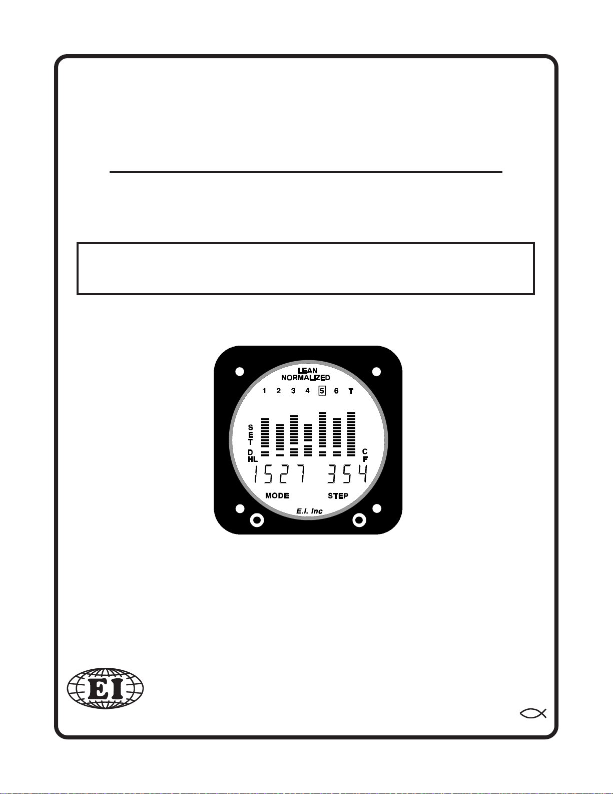
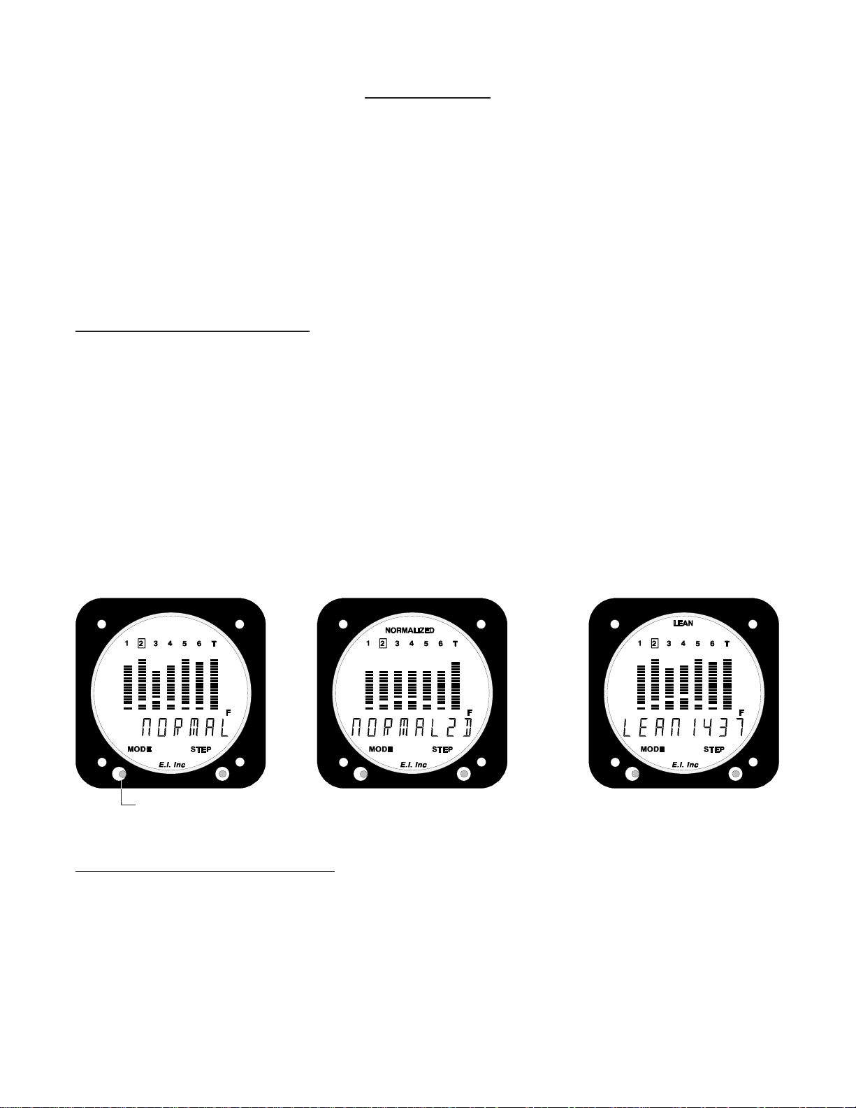
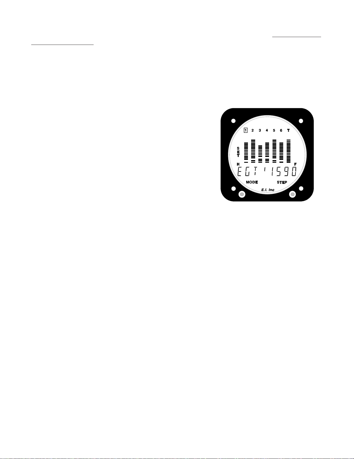
Each time the Mode Switch is pressed to the right, the UBG will advance to the next operating mode. There are
three modes of operation: Normal, Normalized and Lean. The top of the display will indicate in which mode the
UBG is operating. In the Normal Mode (figure 1), there is no indication at the top of the display. In the Normalized Mode (figure 2), the word “NORMALIZED” appears at the top of the display, and in the Lean Mode (figure
3) the word “LEAN” appears.
Also, when switching between the three operating modes, “NORMAL”, NORMALZD” or “LEAN” appears in
the digital display when entering a mode, for as long as the Mode Switch is held to the right. This allows you to
see what mode the UBG is entering even if the top of the display is not visible.
The left position of the Mode Selector Switch is used for programming, which will be covered later in this
manual.
Figure 1Figure 1
Figure 1
Figure 1Figure 1
Mode SwitchMode Switch
Mode Switch
Mode SwitchMode Switch
Normal Operating Mode:Normal Operating Mode:
Normal Operating Mode:
Normal Operating Mode:Normal Operating Mode:
In the Normal Operating Mode, the EGTs are indicated by the height of the lit bars in each of the columns. The
CHTs are indicated by the height of the blanked bars in each of the columns. A CHT of 300’F will cause the
second bar from the bottom to blank. The scaling of the blanked CHT bars is 33’F per bar.
Figure 2Figure 2
Figure 2
Figure 2Figure 2
Figure 3Figure 3
Figure 3
Figure 3Figure 3
3
Page 7
The Bar Graph Display allows visual comparison of EGTs and CHTs at a glance. It also allows you to see where
the EGTs and CHTs are operating in their normal operating range (i.e., high EGTs will be displayed with many
bars lit in a column and low EGTs will be displayed with few bars lit in a column).
The scaling and range of the EGT columns of bars may be customized to accommodate any engine or pilot’s
preference (see the “Programming the Range of the EGT Columns of Bars” section of this manual).
Step Switch:Step Switch:
Step Switch:
Step Switch:Step Switch:
When operating in the Normal or Normalized Operating Mode, each time the Step Switch is pushed to the right
the UBG will advance the digital display to show the next temperature or function. Each time the Step Switch is
pushed to the left the digital display will show the previous temperature or function.
Each time the Step Switch is pushed to the right, the UBG indicates the following temperatures or functions in the
digital display:
1. Displaying the EGTs and CHTs:1. Displaying the EGTs and CHTs:
1. Displaying the EGTs and CHTs:
1. Displaying the EGTs and CHTs:1. Displaying the EGTs and CHTs:
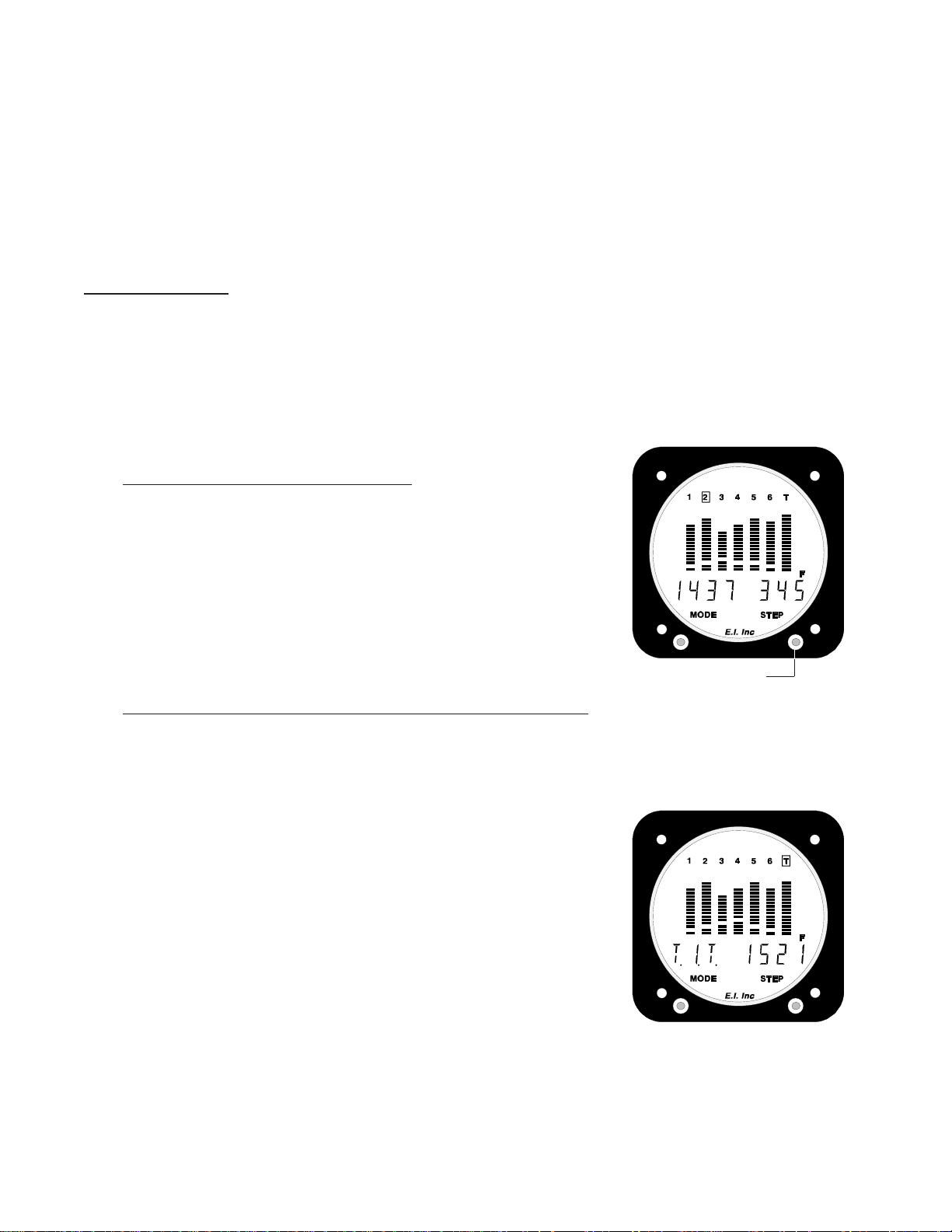
The EGTs and CHTs will be indicated in the digital display, beginning
with cylinder #1. The left side of the digital display will indicate
exhaust gas temperatures and the right side of the digital display will
indicate cylinder head temperatures. The lit box around a specific
cylinder number (located at the top of the columns) coincides with
which cylinder is being digitally displayed. Each time the Step Switch
is pushed to the right the next cylinder will be displayed.
Step SwitchStep Switch
Step Switch
Step SwitchStep Switch
2. Displaying a Temperature on the 7th Column of Bars:2. Displaying a Temperature on the 7th Column of Bars:
2. Displaying a Temperature on the 7th Column of Bars:
2. Displaying a Temperature on the 7th Column of Bars:2. Displaying a Temperature on the 7th Column of Bars:
If installed in a 4 or 6-cylinder engine, after the last EGT channel has been displayed on the UBG, push the
Step Switch once to the right to digitally display the temperature on the 7th column of bars (if the 7th
column is activated). The 7th column of bars may be used to display
EGT and CHT (on a 7-cylinder engine), or TIT or Oil Temperature (on
a 4 or 6-cylinder engine), or it may be turned OFF. Installation and
programming of the UBG will determine what, if any, function will be
displayed on column 7.
The scaling and range of the 7th column of bars may be customized
(independent of the EGT columns) to accommodate any engine or
pilot’s preference (see “Programming the Range of the 7th Column of
Bars”).
4
Page 8
3. Displaying Other Temperatures and/or Functions Digitally:3. Displaying Other Temperatures and/or Functions Digitally:
3. Displaying Other Temperatures and/or Functions Digitally:
3. Displaying Other Temperatures and/or Functions Digitally:3. Displaying Other Temperatures and/or Functions Digitally:
There are a total of 16 input channels on the UBG. The columns
of bars can display EGT, CHT, TIT or Oil. Other functions will be
indicated only in the digital display. While viewing the digital
readout for the last column of bars, push the Step Switch to the
right to display the next temperature or function connected to the
UBG’s input channels.
Note:Note:
Note: While viewing OAT, the digital display may be toggled
Note:Note:
between degrees F and degrees C by pushing the Mode Switch to
the left.
4. Displaying the Shock Cooling Rate:4. Displaying the Shock Cooling Rate:
4. Displaying the Shock Cooling Rate:
4. Displaying the Shock Cooling Rate:4. Displaying the Shock Cooling Rate:
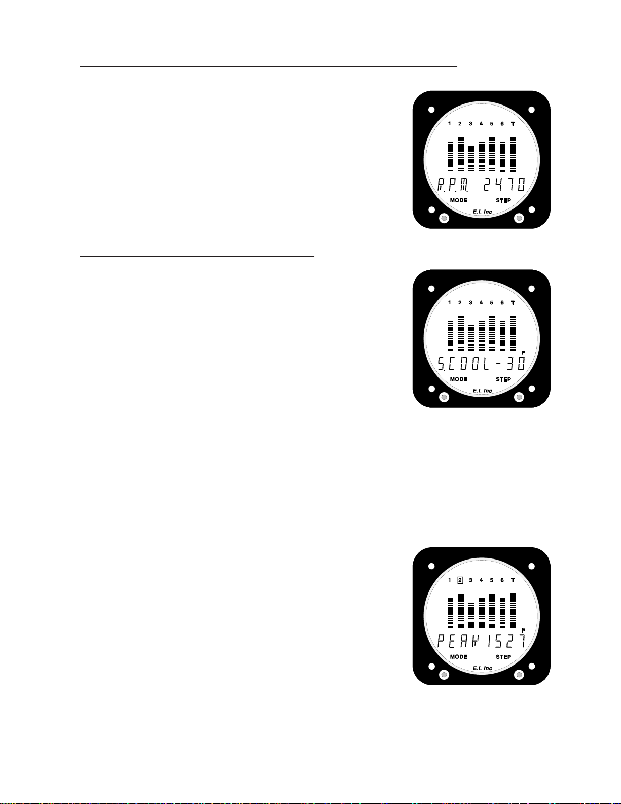
While the last monitored temperature or function is being displayed, push the step switch once to the right to see the Shock
Cooling Rate in the digital display. This is the rate (in degrees F
per minute) at which the indicated cylinder head temperature is
cooling. Normally, cooling will occur only during descent. The
Cylinder Number inside the lit box at the top of the columns is the
programmed shock cooling cylinder being displayed.
Note: An aircraft engine can not be shock cooled when cylinder
head temperatures are below 300'F. For this reason, the UBG-16
will display "-00" when the CHT drops below 300'F.
A Shock Cooling Limit and the cylinder to be monitored for shock cooling are programmable (see
“Programming the Shock Cooling Limit and Cylinder”).
5. Displaying the Peak EGT and Cylinder:5. Displaying the Peak EGT and Cylinder:
5. Displaying the Peak EGT and Cylinder:
5. Displaying the Peak EGT and Cylinder:5. Displaying the Peak EGT and Cylinder:
While the Shock Cooling Rate is being displayed, push the Step Switch once to the right to display the
Peak EGT achieved during the last leaning session. The cylinder
number inside the lit box at the top of the columns is the cylinder
which first reached peak EGT. If you have not leaned the aircraft
during this flight, the Peak EGT from the last time you leaned your
engine will be retrieved from long-term memory and will be
displayed.
Note:Note:
Note: When viewing Peak EGT, the display may be toggled
Note:Note:
between Profile and Peak EGT by pushing the Mode Switch to the
left. While showing Profile, each cylinder’s fuel/air mixture
distribution is displayed in the Bar Graph Display. This is an
advanced feature of the UBG and is described in detail at the back
of this manual.
5
Page 9
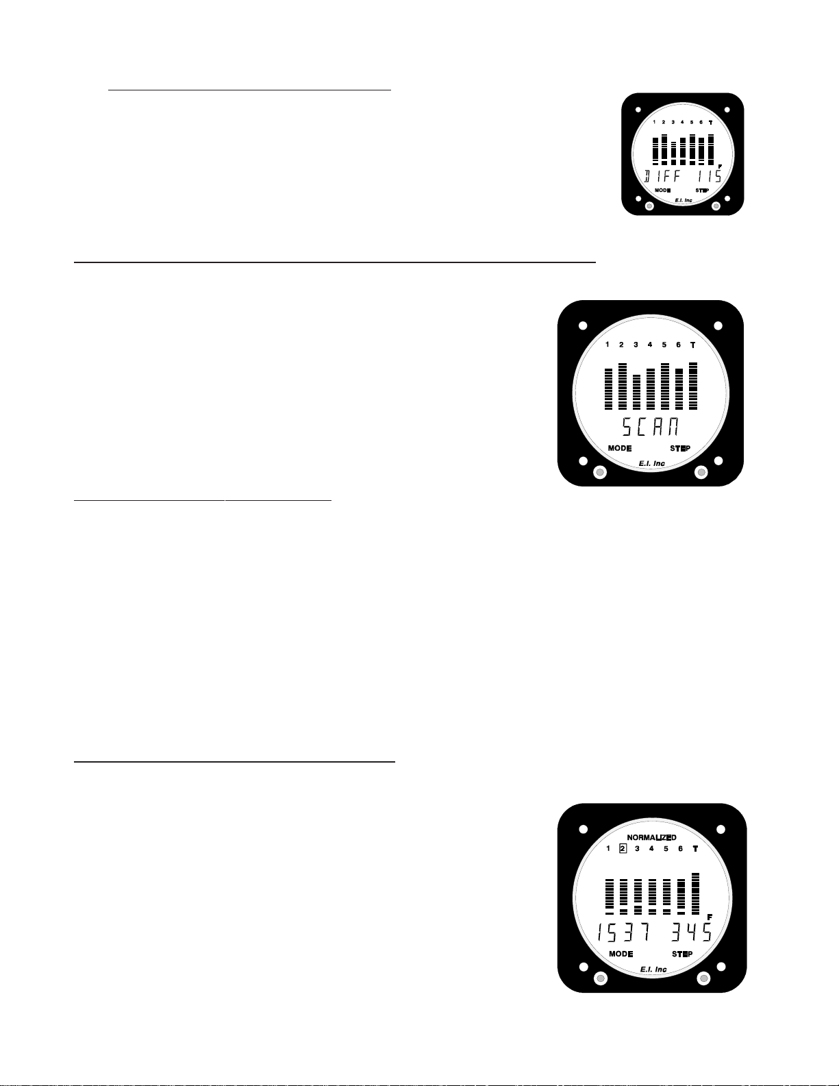
6. Displaying the EGT Difference:6. Displaying the EGT Difference:
6. Displaying the EGT Difference:
6. Displaying the EGT Difference:6. Displaying the EGT Difference:
While the Peak EGT is being displayed, push the Step Switch once to the right to
display the difference between the hottest and coldest EGT. A programmable limit may
be set to alert you when the EGT Differential Limit is exceeded (see “Programming the
EGT Differential Limit”).
Scanning Through the Channels Automatically:Scanning Through the Channels Automatically:
Scanning Through the Channels Automatically:
Scanning Through the Channels Automatically:Scanning Through the Channels Automatically:
When operating in the Normal or Normalized Operating Mode, by pushing
and holding the step switch to the right until the word “SCAN” appears in the
digital display, you may set the UBG to automatically scan the digital display
through the various temperatures and/or functions being monitored. The
length of time a temperature or function will be displayed is programmable.
To cancel the Scan operation, push the step switch to the right or left, or push
the Mode Switch to the right.
If a limit is violated while operating in the Scan Mode, the scan will stop
and the UBG will display the channel with the violation.
When operating in the
grammed by performing the following steps:
1.1.
1. Push and hold the Mode Switch to the left until the word “PROGRAM” appears in the digital display.
1.1.
When the Mode Switch is released, the word “SCAN R. X” will appear in the digital display. The number
blinking (X) in the right portion of the digital display is the Scan Rate in seconds.
22
2. Push the Step Switch right or left to increase or decrease the Scan Rate.
22
33
3. To exit this programming mode, push and hold the Mode Switch to the left until the word “END” ap-
33
pears in the digital display.
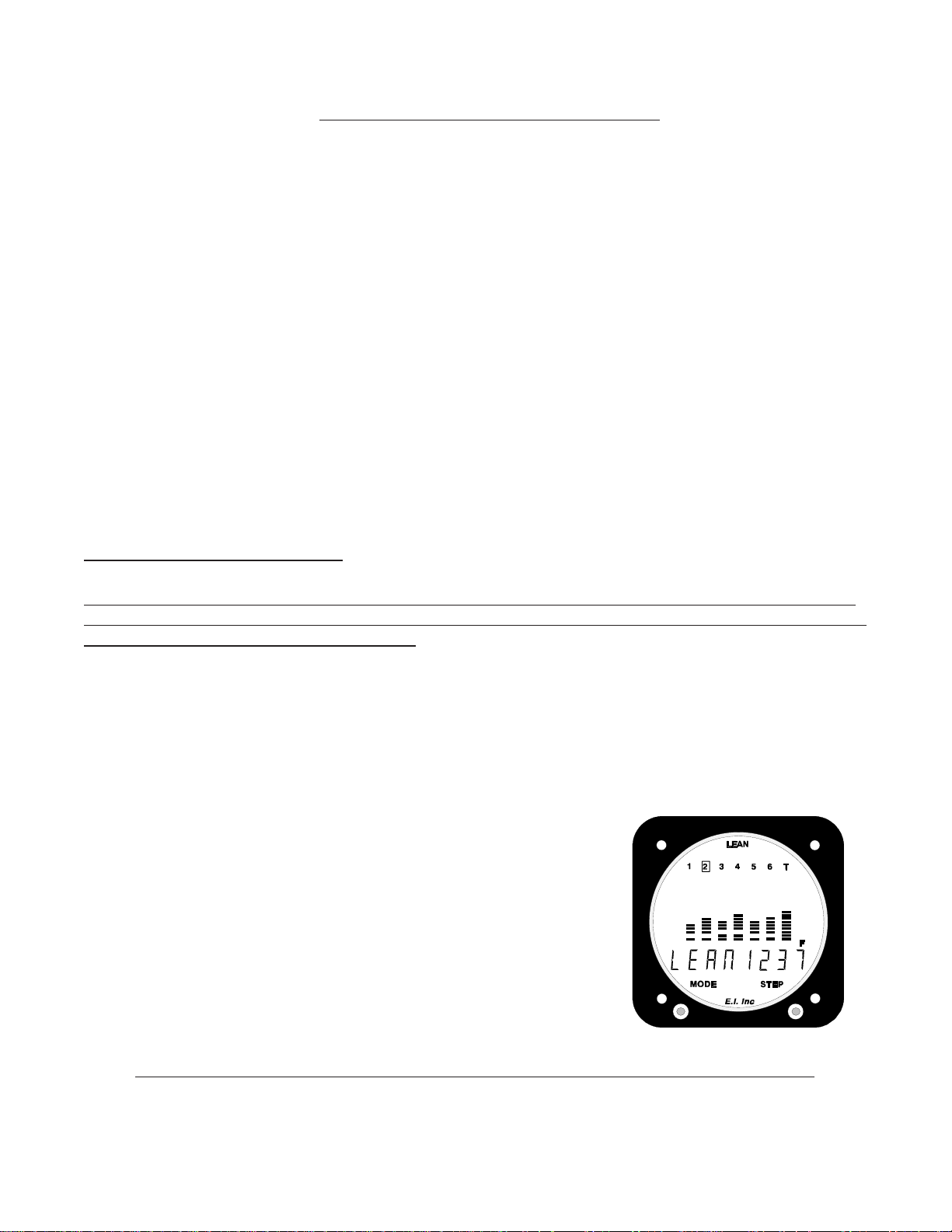
Normalized Operating Mode:Normalized Operating Mode:
Normalized Operating Mode:
Normalized Operating Mode:Normalized Operating Mode:
The purpose of the Normalized Operating Mode is to be able to compare
current engine operation to prior engine operation.
Once the height of the EGT columns has been normalized (brought to the
same level), any abnormal change in the engine’s EGTs will show up as an
abnormally high or low column of bars. In this way you can see temperature
trends over weeks, months or years. The Bar Graph Display provides a
graph of long-term trend, allowing you to spot problems easily.
Scan Mode onlyScan Mode only
Scan Mode only, the Scan Rate may be pro-
Scan Mode onlyScan Mode only
6
Page 10
It is recommended that the EGT columns be normalized while operating your aircraft in normal cruise
flight, with the engine leaned.
normalized on the UBG display by performing the following steps:
1.1.
1. Push and hold the Mode Switch to the left until “PROGRAM” appears in the digital display. Release the
1.1.
Mode Switch and the digital display will show “Normalize N”.
2.2.
2. Push the Step Switch right or left to change the “N” to a “Y” ("NO" to a "YES").
2.2.
3.3.
3. To exit this programming mode, push and hold the Mode Switch to the left until the word “END” ap-
3.3.
pears in the digital display.
Note:Note:
Note: The TIT column of bars will not be affected by normalizing the EGT columns.
Note:Note:
Normalizing brings the EGT columns to the same height and stores the data in memory. Once the EGTs are
normalized, each time you operate your aircraft in normal cruise flight with your engine leaned, you may put the
UBG into its Normalized Operating Mode and look for abnormally high or low columns of bars. Many problems
occur slowly over time. The UBG’s Normalized Operating Mode helps you spot these problems as they occur.
When operating in the
Normalized Mode onlyNormalized Mode only
Normalized Mode only, the EGT bars may be
Normalized Mode onlyNormalized Mode only
Lean Operating Mode:Lean Operating Mode:
Lean Operating Mode:
Lean Operating Mode:Lean Operating Mode:
This manual does not make any recommendations as to specific exhaust gas temperature(s) at which to lean your
engine. Check the airframe and/or engine manufacturer’s recommendations to properly lean your engine. It is the
pilot’s responsibility to lean the engine properly.
We recommend leaning your engine in cruise. A rich running engine wastes fuel and tends to run rough. Good
leaning techniques result in cleaner combustion chambers with fewer lead salt deposits on the pistons and exhaust
valves. Also, proper leaning means less spark plug fouling, longer life for the plugs, reduced maintenance costs
and a considerable fuel savings. Furthermore, proper leaning at cruise during cool or cold weather aids in
raising engine and oil temperatures to desirable minimums in order to evaporate the water and acids out of
the oil. Water and acids attack the insides of an engine, causing rust and corrosion.
When you enter the Lean Operating Mode of the UBG, the right portion of
the digital display will show the current EGT for the cylinder which peaked
first the last time you leaned your engine. The word “LEAN” will be
displayed in the left portion of the digital display. The UBG will not activate
the Lean Operating Mode until the hottest EGT has raised 10’F.
Most engines will exhibit a 200 to 350’F rise in EGTs before a cylinder
reaches peak. Start the leaning process by rough leaning your engine near
peak EGT (pull the mixture back to a predetermined setting or use a fuel
flow instrument). Experience should be your guide. Do not lean past
peak EGT during rough leaning.
Note: Note:
Note:
Note: Note:
It is not recommended to lean an engine for peak EGT above 75% power setting.It is not recommended to lean an engine for peak EGT above 75% power setting.
It is not recommended to lean an engine for peak EGT above 75% power setting.
It is not recommended to lean an engine for peak EGT above 75% power setting.It is not recommended to lean an engine for peak EGT above 75% power setting.
7
Page 11

Next, slowly lean your engine by pulling the mixture out a very small amount. When the increase in
temperature slows to less than one degree per second, once again lean the engine a very small amount.
The slower you lean, the more accurate the results will be.
When any cylinder reaches its peak (hottest) EGT and starts to decrease
in temperature, the digital display will blink the word “PEAK” in the left
portion of the display and the hottest (Peak) EGT reached will be displayed
in the right portion of the display. The cylinder number inside the lit box at
the top of the columns is the first cylinder to reach peak EGT. That cylinder
number will blink, indicating the cylinder is now operating on the lean side
of peak. Also, the external warning light will blink.
Push the Step Switch to the right or left to acknowledge the peak and to stop
the blinking of the word “PEAK” in the digital display as well as the blinking
of the External Warning Light. At that time the current EGT will be
displayed in the right portion of the digital display.
1. False Peaks:1. False Peaks:
1. False Peaks:
1. False Peaks:1. False Peaks:
As you lean your engine, a dip in an exhaust gas temperature could occur for many reasons (e.g., mixture
linkage issues, non-linearity in fuel servo or carburetor mechanism, a small change in the pitch of the
aircraft, a small change in the air distribution as the engine torque and/or RPM changes, etc.). This dip in an
EGT can cause engine analyzers to indicate a false peak.
After the Peak EGT is found, continue to lean gradually. If the Peak EGT indication is actually only a dip
(false peak), the EGT will once again start to increase. When it increases above the false peak the UBG will
switch back to the leaning mode (the left portion of the digital display will show “LEAN”). This capability
is essential in eliminating false peaks.
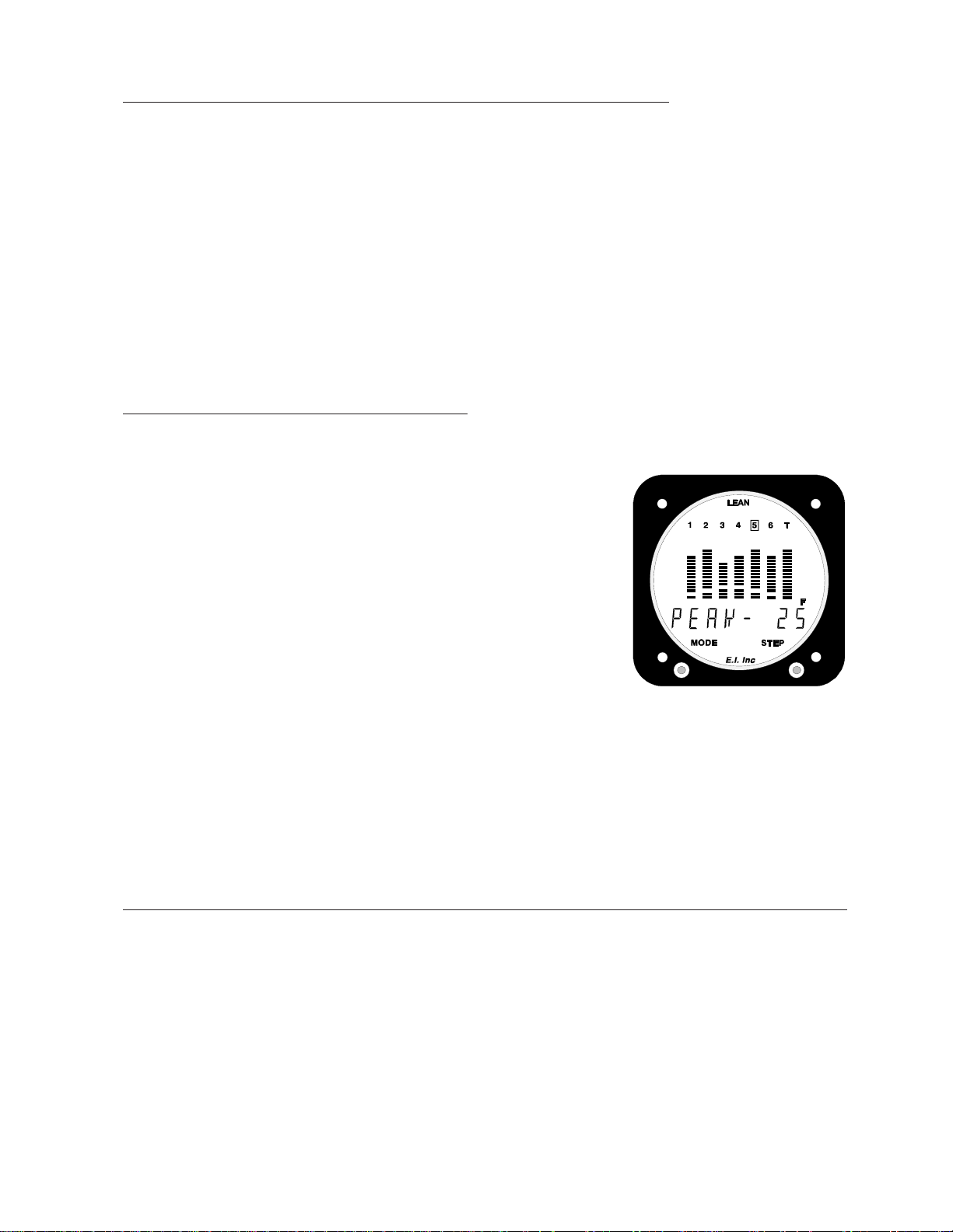
2. Leaning on the Rich Side of Peak:2. Leaning on the Rich Side of Peak:
2. Leaning on the Rich Side of Peak:
2. Leaning on the Rich Side of Peak:2. Leaning on the Rich Side of Peak:
Once the first cylinder to reach peak is found and you have stopped the blinking by pushing the step
switch, enrichen the mixture and push the Mode Switch to the left to cause the digital display to show
the Temperature Below Peak EGT for that cylinder (e.g., “PEAK 25”). Displaying the Temperature Below Peak EGT makes it very
easy to set the mixture to a specific EGT on the rich (or lean) side
of peak.
Note:Note:
Note: Each time the Mode Switch is pushed to the left, the right
Note:Note:
portion of the digital display will alternate between displaying the
current EGT and the Temperature Below Peak.
Note:Note:
Note: As you enrichen the mixture, the exhaust gas temperatures of all
Note:Note:
of the cylinders will decrease. This will cause the cylinder numbers above all of the columns of bars to blink. A blinking cylinder
number indicates that cylinder’s EGT has decreased from the
highest temperature it achieved.
8
Page 12
3. Alternate Method for Leaning on the Rich Side of Peak:3. Alternate Method for Leaning on the Rich Side of Peak:
3. Alternate Method for Leaning on the Rich Side of Peak:
3. Alternate Method for Leaning on the Rich Side of Peak:3. Alternate Method for Leaning on the Rich Side of Peak:
The following method will work only if the peak EGT is near the same temperature for every flight, which is
common for many engines operating on the rich side of peak.
Once the first cylinder to reach peak is found and you have enrichened the mixture to your normal exhaust
gas temperature during cruise, note the normal operating temperatures for each cylinder. Set each cylinder’s
High EGT Limit at its normal operating temperature plus 15’F.
Thereafter when you lean, simply rough lean the engine until you see a High Limit Warning displayed on
the UBG. Enrichen the mixture slightly until the High Limit Warning goes out . . . you’re done! You do not
have to enter the Lean Operating Mode nor do you have to look at the UBG display to perform this leaning
method.
4. Leaning on the Lean Side of Peak:4. Leaning on the Lean Side of Peak:
4. Leaning on the Lean Side of Peak:
4. Leaning on the Lean Side of Peak:4. Leaning on the Lean Side of Peak:
Once the first cylinder to reach peak is found, continue to lean the
mixture and push the Mode Switch to the left to cause the digital
display to show the Temperature Below Peak EGT for that cylinder
(example: “PEAK -25). Displaying the Temperature Below Peak EGT
makes it very easy to set the mixture for a specific EGT on the lean
side of peak.
As each cylinder begins to run on the lean side of peak, the cylinder
number above the appropriate column of bars will blink. You easily
can see as each cylinder reaches peak and you can see the status of
each cylinder (whether it’s on the rich or lean side of peak) at a glance.
Note:Note:
Note: The UBG eliminates false peaks on all cylinders, including
Note:Note:
TIT.
Note:Note:
Note: The Step Switch may be used to display the Temperature Below Peak for any cylinder. This can be
Note:Note:
an invaluable tool in helping to lean your engine properly on the lean side of peak.
Note:Note:
Note: Each time the Mode Switch is pushed to the left, the right portion of the digital display will alternate
Note:Note:
between displaying the current EGT and the Temperature Below Peak.
5. Method for Checking the Mixture Setting when Operating on the Lean Side of Peak:5. Method for Checking the Mixture Setting when Operating on the Lean Side of Peak:
5. Method for Checking the Mixture Setting when Operating on the Lean Side of Peak:
5. Method for Checking the Mixture Setting when Operating on the Lean Side of Peak:5. Method for Checking the Mixture Setting when Operating on the Lean Side of Peak:
If you are running all of the cylinders on the lean side of peak, you can do a quick check on your mixture
setting by performing the following:
A.A.
A. Enter the Lean Operating Mode.
A.A.
B.B.
B. Very slowly enrichen the mixture until peak EGT is found. Since all of the cylinders are running
B.B.
on the lean side of peak, all of the EGTs will rise. The first cylinder to reach peak will be the richest
cylinder.
9
Page 13
C.C.
C. Push the Mode Switch twice to the left to acknowledge the peak and to cause the display to
C.C.
show the Temperature Below Peak.
D.D.
D. Lean the mixture to a desired Temperature Below Peak for the richest cylinder.
D.D.
Alarms:Alarms:
Alarms:
Alarms:Alarms:
The UBG offers up to 16 High and 16 Low Alarms (one high and one low alarm for each input channel), one EGT
Differential Alarm and one Shock Cooling Alarm. These alarms are part of the UBG’s awesome power to detect
most problems automatically, the moment they occur. The UBG performs a full analysis on all temperatures and
functions every one-half second . . . a much faster and more accurate method of detecting problems than downloading data to a computer and analyzing it every six months to try to find an engine problem, as with other bar
graph units.
1. High and Low Alarm Annunciators:1. High and Low Alarm Annunciators:
1. High and Low Alarm Annunciators:
1. High and Low Alarm Annunciators:1. High and Low Alarm Annunciators:
If any one of the programmed High or Low Limits is violated, the UBG will blink a “H” or “L” on the
left side of the display. Also, the External Warning Light will blink.
2. EGT Differential Alarm Annunciator:2. EGT Differential Alarm Annunciator:
2. EGT Differential Alarm Annunciator:
2. EGT Differential Alarm Annunciator:2. EGT Differential Alarm Annunciator:
If the difference between the hottest and coldest EGT violates the
programmed EGT Differential Limit, the UBG will blink a “D” on
the left side of the display. Also, the External Warning Light will
blink.
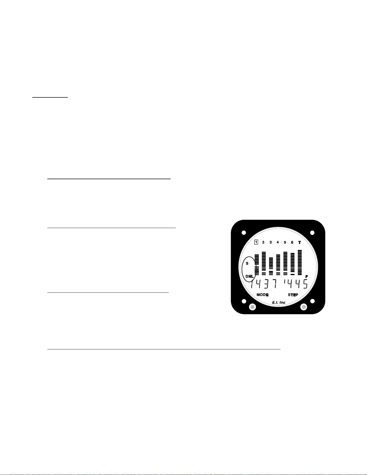
3. Shock Cooling Alarm Annunciator:3. Shock Cooling Alarm Annunciator:
3. Shock Cooling Alarm Annunciator:
3. Shock Cooling Alarm Annunciator:3. Shock Cooling Alarm Annunciator:
If the programmed Shock Cooling Limit is violated, the UBG
will blink a “S” on the left side of the display. Also, the
External Warning Light will blink.
4. Finding the Channel on which a Programmed Limit has been Violated:4. Finding the Channel on which a Programmed Limit has been Violated:
4. Finding the Channel on which a Programmed Limit has been Violated:
4. Finding the Channel on which a Programmed Limit has been Violated:4. Finding the Channel on which a Programmed Limit has been Violated:
If one of the temperatures or functions monitored on the UBG has violated a programmed limit, put the
UBG into the Scan Mode (hold the Step Switch to the right until the digital display shows “SCAN”). The
digital display will jump to the temperature or function that has the problem (a limit violation). Each time
the UBG is put into the Scan Mode, the next temperature or function with a problem will be displayed.
If you are viewing the temperature channel or function which is violating a high or low limit, a high or low
bar will be blinking in the digital display.
Note:Note:
Note: When viewing the EGT Difference or Shock Cooling, a high bar will blinking in the digital display.
Note:Note:
10
Page 14

5. Canceling all Active Alarms for 10 Minutes:5. Canceling all Active Alarms for 10 Minutes:
5. Canceling all Active Alarms for 10 Minutes:
5. Canceling all Active Alarms for 10 Minutes:5. Canceling all Active Alarms for 10 Minutes:
To cancel all active alarms for 10 minutes, push and hold the Step
Switch to the left until the word “CANCEL” appears in the digital
display. Any new alarm (i.e., an alarm set after this step is performed)
will be displayed and will not be affected by the 10-minute cancellation
of alarms.
6. Activating all Canceled Alarms:6. Activating all Canceled Alarms:
6. Activating all Canceled Alarms:
6. Activating all Canceled Alarms:6. Activating all Canceled Alarms:
To activate all canceled alarms, push and hold the Step Switch to
the right until the word “SCAN” appears in the digital display.
Programming the 34 Limits:Programming the 34 Limits:
Programming the 34 Limits:
Programming the 34 Limits:Programming the 34 Limits:
The 34 pilot-programmable limits allow you to customize the UBG to your engine. Trend analysis and problem
detection is done automatically every one-half second. You are alerted as soon as a limit is violated.
While programming limits, keep in mind that setting limits just outside normal operating ranges allows potential
problems to be detected early, without causing a false warning. Not only are false warnings annoying, but they
can desensitize you to warnings in general. This in itself could cause a problem.
The “Work Sheet for Setting High and Low Limits” located at the back of this manual may be helpful in setting
proper limits.
Programming the High and Low EGT and CHT Limits:Programming the High and Low EGT and CHT Limits:
Programming the High and Low EGT and CHT Limits:
Programming the High and Low EGT and CHT Limits:Programming the High and Low EGT and CHT Limits:
It is recommended that EGT and CHT limits be set just outside each cylinder’s normal operating range so problems can be detected without causing a false warning.
Exhaust gas temperatures are directly related to your engine’s ability to produce power. If any cylinder has a
problem producing power (fouled plug, burned or stuck valve, broken ring, intake leak, plugged injector, timing
problem, bad mag, etc.) the exhaust gas temperature for that cylinder will be abnormally high or low, depending
on the problem. Each of your engine’s cylinders operates differently and has a “normal” operating temperature of
its own. The UBG is capable of being programmed to take into account each cylinder’s individual operating
temperature. When selecting and programming the EGT limits on the UBG, it is assumed your engine does not
have a current problem and it is operating properly.
1. Selecting the High EGT Limits:1. Selecting the High EGT Limits:
1. Selecting the High EGT Limits:
1. Selecting the High EGT Limits:1. Selecting the High EGT Limits:
At 75% power, lean your engine to peak EGT. Record the EGT readings for each cylinder. Program the
High Limit for each cylinder 40’F above the recorded readings for that cylinder. This is only a
11
Page 15

recommended limit. As you get to know your engine’s normal operating temperatures, you may want
to adjust these limits accordingly.
2. Selecting the Lower EGT Limits:2. Selecting the Lower EGT Limits:
2. Selecting the Lower EGT Limits:
2. Selecting the Lower EGT Limits:2. Selecting the Lower EGT Limits:
In normal cruise, at low altitude, adjust the mixture full rich and wait for the EGTs to stabilize. Once the
EGTs have stabilized, record the EGT readings for each cylinder. Program the Lower Limit for each
cylinder 40’F below the recorded readings for that cylinder. This is only a recommended limit. As you get
to know your engine’s normal operating temperatures, you may want to adjust these limits accordingly.
During climbs, the cylinder head temperatures will rise rapidly until the heat absorbed by the combustion walls is
dissipated through the engine’s cooling fins. At this point, the CHTs will stabilize. Any change in throttle,
mixture, cowl, OAT or airspeed will affect the CHTs and their rate of change. Since rate and trend information
can be interpreted easily on the UBG digital display, changing any one of these parameters to stabilize, slow or
reduce the CHT is possible with almost immediate results.
Cylinder head temperatures are related to your engine’s ability to produce power. If any cylinder has a problem
producing power (fouled plug, burned or stuck valve, broken ring, intake leak, plugged injector, timing problem,
bad mag, etc.) the cylinder head temperature for that cylinder may or may not be abnormally high or low, depending on the extent of the problem. Generally, we have not found cylinder head temperatures to be a good tool for
detecting problems. However, CHTs are a good indicator of excessively high power settings.
Each of your engine’s cylinders operates differently and has a normal operating temperature of its own. The UBG
is capable of being programmed to take into account each cylinder’s individual operating temperature. When
selecting and programming the CHT limits on the UBG, it is assumed your engine currently does not have a
problem and it is operating properly.
3. Selecting the High CHT Limits:3. Selecting the High CHT Limits:
3. Selecting the High CHT Limits:
3. Selecting the High CHT Limits:3. Selecting the High CHT Limits:
Near the middle or end of a long climb, preferably on a hot day, record the CHT readings for each cylinder.
Program the High CHT Limits for each cylinder 40’F above the recorded reading for that cylinder.
Note:Note:
Note: The High CHT Limits should not be set higher than the maximum limit allowed for your aircraft.
Note:Note:
4. Selecting the Lower CHT Limits:4. Selecting the Lower CHT Limits:
4. Selecting the Lower CHT Limits:
4. Selecting the Lower CHT Limits:4. Selecting the Lower CHT Limits:
The CHT Low Limits should be set to 150’F. Operating your aircraft with CHTs below 150’F is not recommended. The large difference between the combustion temperatures and low CHT temperatures can cause
engine damage.
12
Page 16
High and low EGT and CHT limits may be set for each cylinder displayed on the UBG.
Normal Mode onlyNormal Mode only
Normal Mode only, the EGT and CHT limits may be set by performing the following steps:
the
Normal Mode onlyNormal Mode only
A.A.
A. Select the cylinder on which the limits are to be programmed.
A.A.
B.B.
B. Press and hold the mode switch to the left until the word “PROGRAM” appears in the digital display.
B.B.
Release the Mode Switch. “SET H” will appear on the left side of the UBG display. Also, “EGT” will
appear in the left portion of the digital display and the right
portion will show the current high limit. The digit on the far
left will be blinking.
C.C.
C. Use the Step Switch to increase or decrease the digit which is
C.C.
blinking. The EGT Limits can be set from 0 to 1990’F in 10’F
increments and the CHT Limits can be set from 0 to 499’F in 1’F
increments (although the CHT limit will be converted down to an
even number).
D.D.
D. Use the Mode Switch to blink a specific digit.
D.D.
When operating in
E.E.
E. To change functions, push the Mode Switch to the right (or left) until the digital display shows the
E.E.
function you wish to program. The functions will appear in the following order:
1.1.
1. EGT High Limit.
1.1.
2.2.
2. EGT Low Limit.
2.2.
3.3.
3. CHT High Limit.
3.3.
4.4.
4. CHT Low Limit.
4.4.
5.5.
5. Upper EGT Bar Trip Point (programmed on cylinder #1 only).
5.5.
6.6.
6. Lower EGT Bar Trip Point (programmed on cylinder #1 only).
6.6.
Note:Note:
Note: Setting a limit to “000” will disable the limit and any alarms.
Note:Note:
F.F.
F. To exit this programming mode, push and hold the Mode Switch to the left until the word “END”
F.F.
appears in the digital display.
13
Page 17

Programming the Range of the EGT Columns of Bars:Programming the Range of the EGT Columns of Bars:
Programming the Range of the EGT Columns of Bars:
Programming the Range of the EGT Columns of Bars:Programming the Range of the EGT Columns of Bars:
The range of the EGT columns of bars may be customized to accommodate any engine or pilot preference. This
is done by programming the temperatures at which the Upper and Lower Bars come on (Trip Points). The objective in setting the Trip Points is to get the height of the EGT bars low in their columns during a climb, and high in
their columns when the engine is leaned or near peak EGT.
1. Selecting the Upper EGT Bar Trip Point:1. Selecting the Upper EGT Bar Trip Point:
1. Selecting the Upper EGT Bar Trip Point:
1. Selecting the Upper EGT Bar Trip Point:1. Selecting the Upper EGT Bar Trip Point:
At 75% power, lean your engine to peak EGT. Record the EGT temperatures for each cylinder. Program
the Upper EGT Bar Trip Point 50’F above the recorded highest EGT temperature. As you get to know your
engine’s normal operating temperatures, you may want to adjust this Trip Point.
2. Selecting the Lower EGT Bar Trip Point:2. Selecting the Lower EGT Bar Trip Point:
2. Selecting the Lower EGT Bar Trip Point:
2. Selecting the Lower EGT Bar Trip Point:2. Selecting the Lower EGT Bar Trip Point:
In a normal cruise power condition, at low altitude, adjust the mixture to full rich and wait for the EGTs to
stabilize. Once the EGTs have stabilized, record the EGT temperatures for each cylinder. Program the
Lower EGT Bar Trip Point 100’F below the lowest recorded EGT temperature. As you get to know your
engine’s normal operating temperatures you may want to adjust this Trip Point.
When operating in the
following steps:
1.1.
1. Select cylinder #1 using the Step Switch.
1.1.
2.2.
2. Press and hold the mode switch to the left until the word
2.2.
“PROGRAM” appears in the digital display.
3.3.
3. Push the Mode Switch to the right several times until you see
3.3.
“BAR” in the left portion of digital display and “SET H” on the
left side of the UBG display. The right portion of the digital
display will show the current Upper EGT Bar Trip Point. The
digit to the far left will be blinking.
4.4.
4. Use the Step Switch to increase or decrease the digit that is
4.4.
blinking. The Upper and Lower Bar Trip Points can be set from 0
to 1990’F in 10’F increments.
Normal Mode onlyNormal Mode only
Normal Mode only, the Upper and Lower Bar Trip Points may be set by performing the
Normal Mode onlyNormal Mode only
5.5.
5. Use the Mode Switch to blink a specific digit.
5.5.
6.6.
6. To program the Lower Bar, push the Mode Switch to the right until the UBG shows “SET L” on left side
6.6.
of the UBG display.
14
Page 18

7.7.
7. To exit this programming mode, push and hold the Mode Switch to the left until the word “END”
7.7.
appears in the digital display.
Programming the High and Low Limits and Range of the 7th Col-Programming the High and Low Limits and Range of the 7th Col-
Programming the High and Low Limits and Range of the 7th Col-
Programming the High and Low Limits and Range of the 7th Col-Programming the High and Low Limits and Range of the 7th Column of Bars:umn of Bars:
umn of Bars:
umn of Bars:umn of Bars:
The 7th column of bars may be used to display EGT and CHT on a 7-cylinder engine, TIT or Oil Temperature, or
it may be turned off. A High and Low Limit may be programmed for whatever temperature is displayed on the
7th column of bars.
If the 7th column is used to display TIT or Oil Temperature, the range of the 7th column of bars may be customized to accommodate any temperature, engine or pilot preference. This is done by programming the temperatures
at which the Upper and Lower Bars come on (Trip Points).
If the 7th column is used to display EGT and CHT for a 7 cylinder engine, see “Programming the High and Low
EGT and CHT Limits” above. Otherwise, when operating in the
1.1.
1. Select the 7th column using the Step Switch.
1.1.
Normal Mode onlyNormal Mode only
Normal Mode only, perform the following steps:
Normal Mode onlyNormal Mode only
2.2.
2. Press and hold the mode switch to the left until the word “PROGRAM” appears in the digital display.
2.2.
Release the Mode Switch and “SET H” will appear on the left side of the UBG display. Also, “TIT” or
“OIL.T” will appear in the left portion of the digital display and the right portion will show the current
Height Limit. The digit to the far left will be blinking.
3.3.
3. Use the Step Switch to increase or decrease the digit that is
3.3.
blinking. The High and Low Limits and Trip Points can be set
from 0 to 1990’F in 10’F increments.
4.4.
4. Use the Mode Switch to blink a specific digit.
4.4.
5.5.
5. To change functions, push the Mode Switch to the right (or left)
5.5.
until the digital display shows the function you wish to program.
The functions will appear in the following order:
A.A.
A. “TIT” or “OIL.T”, High Limit.
A.A.
B.B.
B. “TIT” or “OIL.T”, Low Limit.
B.B.
C. C.
C. Upper Bar Trip Point.
C. C.
D. D.
D. Lower Bar Trip Point.
D. D.
15
Page 19

Note:Note:
Note: Setting a limit to “000” will disable the limit and any alarms.
Note:Note:
6.6.
6. To exit this programming mode, push and hold the Mode Switch to the left until the word “END” appears
6.6.
in the digital display.
Programming the High and Low Limits for Other Temperatures orProgramming the High and Low Limits for Other Temperatures or
Programming the High and Low Limits for Other Temperatures or
Programming the High and Low Limits for Other Temperatures orProgramming the High and Low Limits for Other Temperatures or
Functions:Functions:
Functions:
Functions:Functions:
It is recommended that high and low limits be set just outside the normal operating range for your engine so
problems can be detected without causing a false warning. False warnings are annoying and can desensitize you
to warnings in general. This could cause a serious delay in taking note of a warning which is an alert to a real
problem.
A High and Low Limit may be set for any temperature or function displayed on the UBG. When operating in the
Normal Mode onlyNormal Mode only
Normal Mode only, the High and Low Limits may be set by performing the following steps:
Normal Mode onlyNormal Mode only
1.1.
1. Select the temperature or function on the digital display.
1.1.
2.2.
2. Press and hold the mode switch to the left until the word “PROGRAM” appears in the digital display.
2.2.
Release the Mode Switch. “SET H” will appear on the left side of the UBG display. Also, the High Limit
will appear in the right portion of the digital display and the digit
to the far left will be blinking.
3.3.
3. Use the Step Switch to increase or decrease the digit that is
3.3.
blinking. The limits are set as shown in the chart following this
section.
4.4.
4. Use the Mode Switch to blink a specific digit.
4.4.
5.5.
5. To display the Low Limit, push the Mode Switch to the right
5.5.
until “SET L” appears on the left side of the UBG display.
Note:Note:
Note: Setting a limit to “000” will disable the limit and any alarms.
Note:Note:
6.6.
6. To exit this programming mode, push and hold the Mode Switch to the left until the word “END” ap-
6.6.
pears in the digital display.
16
Page 20

yalpsiD
noitcnuFropmeT
TGE)F'1-/+(/F'9991ot0.)F'01-/+(/F'0991ot0
)noituloseR(/egnaR
timiLwoLdnahgiH
)noituloseR(/egnaR
THC)F'1-/+(/F'999ot0
.T.I.T)F'1-/+(/F'9991ot0.)F'01-/+(/F'0991ot0
pmeTliO)F'1-/+(/F'999ot0
.T.A.O)F'1-/+(/F'999ot0
pmeTbraC)F'1-/+(/F'999ot0
pmeTlwoC)F'1-/+(/F'999ot0
pmeT)F'1-/+(/F'9991ot0.)F'01-/+(/F'0991ot0
)isp1-/+(/999ot0
erusserPliO
erusserPleuF
erusserPdlofinaM
isp5wolebsgnidaeR
.isp0sayalpsid
)isp1.-/+(/9.99ot0
isp0.1wolebsgnidaeR
.isp0sayalpsid
).gH"1.-/+(/9.99ot0
.gH"0.1wolebsgnidaeR
.gH"0sayalpsid
nevenaotnwoddetrevnoc,F'1-/+(/F'994ot0
.)rebmun
nevenaotnwoddetrevnoc,F'1-/+(/F'994ot0
.)rebmun
nevenaotnwoddetrevnoc,F'1-/+(/F'994ot0
.)rebmun
nevenaotnwoddetrevnoc,F'1-/+(/F'994ot0
.)rebmun
nevenaotnwoddetrevnoc,F'1-/+(/F'994ot0
.)rebmun
naotnwoddetrevnoc,isp1-/+(/isp994ot0
.)rebmunneve
naotnwoddetrevnoc,isp1.0-/+(/isp9.94ot0
.)rebmunneve
otnwoddetrevnoc,.gH"1.0-/+(/.gH"9.94ot0
.)rebmunnevena
muucaVoryG
.M.P.R01-/+(/MPR0994ot0
wolFleuF
stloVsuB
spmA
laitnereffiDTGE)F'1-/+(/F'999ot0
gnilooCkcohS)F'1-/+(/F'99ot0
).gH"1.-/+(/9.99ot0
.gH"0.1wolebsgnidaeR
.gH"0sayalpsid
)MPR
1.-/+(/HPG9.99ot0
wolebsgnidaeR)HPG
0sayalpsidHPG5.0
.HPG
)V1.0-/+(/V9.99ot0
V5.0wolebsgnidaeR
.V0sayalpsid
)A1-/+(/A999ot0
A5wolebsgnidaeR
.A0sayalpsid
.)rebmun
.)rebmun
.)rebmun
.)rebmunnevena
.)MPR01-/+(/MPR0994ot0
.)rebmunnevena
.)rebmunneve
otnwoddetrevnoc,.gH"1.0-/+(/.gH"9.94ot0
otnwoddetrevnoc,.HPG1.0-/+(/HPG9.94ot0
naotnwoddetrevnoc,V1.0-/+(/V9.94ot0
nevenaotnwoddetrevnoc,A1-/+(/A994ot0
nevenaotnwoddetrevnoc,F'1-/+(/F'994ot0
nevenaotnwoddetrevnoc,F'1-/+(/F'99ot0
17
Page 21

Programming the Shock Cooling Limit and Cylinder:Programming the Shock Cooling Limit and Cylinder:
Programming the Shock Cooling Limit and Cylinder:
Programming the Shock Cooling Limit and Cylinder:Programming the Shock Cooling Limit and Cylinder:
Sudden cooling of the CHT (known as shock cooling) is a common problem in some engines. In others, it is rare.
Shock cooling an engine can result in bent pushrods due to exhaust valves sticking, burned valves, spark plug
fouling, broken piston rings, cracked cylinders at the spark plug and valve ports and warped exhaust valves.
A shock cooling limit may be set to alert when an engine’s CHTs are cooling too rapidly. In one Lycoming
document, it is recommended that the CHTs decrease no more than 20’F per minute. In another of its documents,
Lycoming recommends a decrease of no more than 40’F per minute.
Normal Mode onlyNormal Mode only
You may want to start with a Shock Cooling Limit of 30’F per minute. When operating in the
and displaying Shock Cooling ("SCOOL")and displaying Shock Cooling ("SCOOL")
and displaying Shock Cooling ("SCOOL"), the Shock Cooling Limit may be set by performing the following
and displaying Shock Cooling ("SCOOL")and displaying Shock Cooling ("SCOOL")
steps:
1.1.
1. Press and hold the mode switch to the left until the word “PRO-
1.1.
GRAM” appears in the digital display. Release the Mode Switch.
“SET” will appear on the left side of the UBG display. Also,
“S.COOL-XX” will appear in the left portion of the digital display
and the right portion will show the current Shock Cooling Limit
(“XX”). The digit to the far left will be blinking.
Normal Mode only
Normal Mode onlyNormal Mode only
2.2.
2. Use the Step Switch to increase or decrease the digit that is
2.2.
blinking. The Shock Cooling Limit can be set from 0 to 99’F per
minute in 1’F increments.
3.3.
3. Use the Mode Switch to blink a specific digit.
3.3.
4.4.
4. To set the cylinder to be monitored, push the Mode Switch to the right until the digital display shows
4.4.
“S.C. CH X”. The right portion of the digital display will show the current cylinder (“X”) on which the
shock cooling rate is monitored. Use the Step Switch to change the cylinder number. You should monitor
one of the front, unobstructed cylinders.
5.5.
5. To exit this programming mode, push and hold the Mode Switch to the left until the word “END” appears
5.5.
in the digital display.
Note:Note:
Note: Setting a limit to “000” will disable the limit and any alarms.
Note:Note:
Programming the EGT Differential Limit:Programming the EGT Differential Limit:
Programming the EGT Differential Limit:
Programming the EGT Differential Limit:Programming the EGT Differential Limit:
It is recommended to set the EGT Differential Limit just outside the normal operating range for your engine so
problems can be detected without causing false warnings. False warnings are annoying and can desensitize you to
warnings in general. This could cause a serious delay in taking note of a warning which is an alert to a real
problem.
18
Page 22
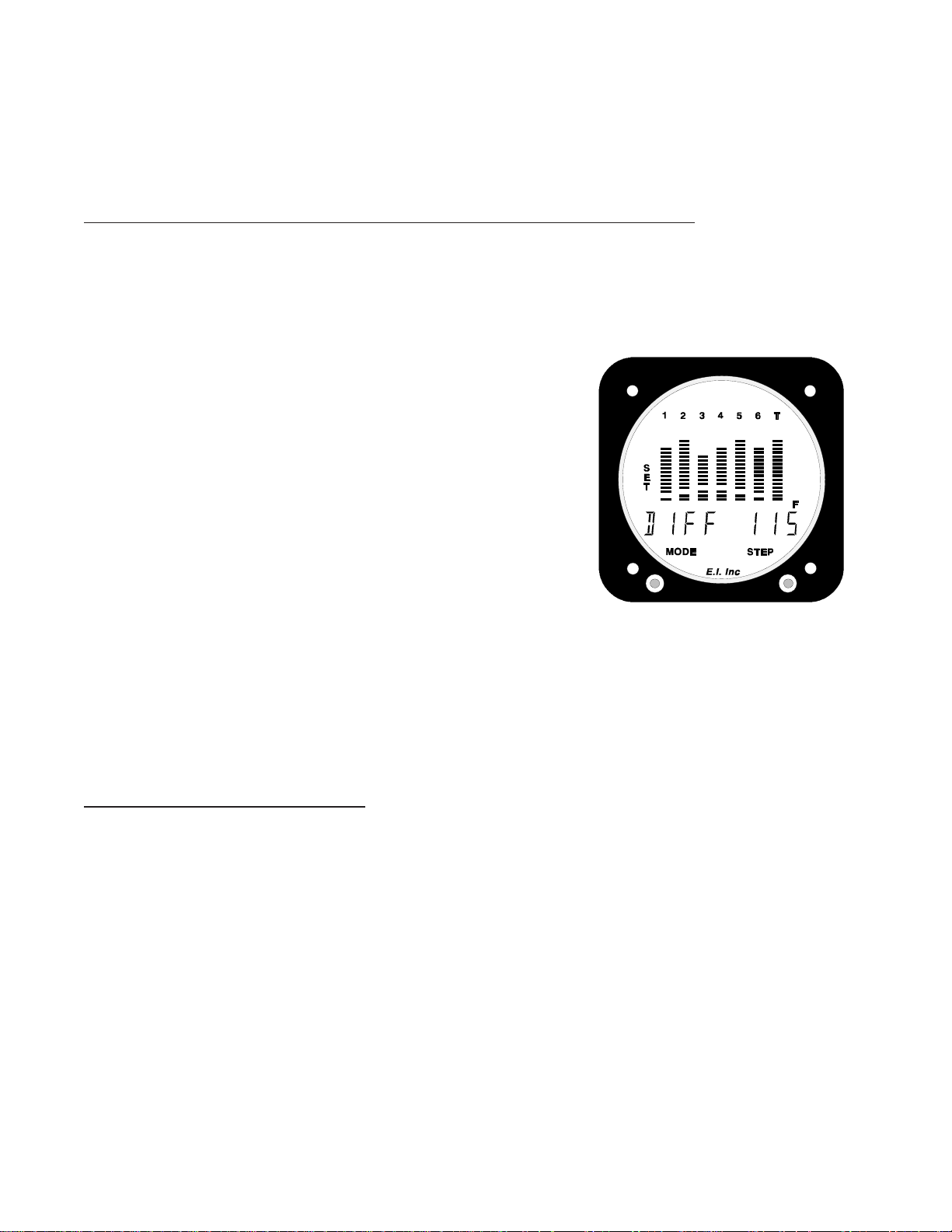
Your engine’s EGTs will vary at different power, altitude and mixture settings. To further enhance the
UBG’s ability to detect a problem, select the EGT Difference (“DIFF”) on the UBG’s digital display and
note the EGT Difference during climb, cruise and descent. Set the EGT Differential Limit for 30’F higher
than the observed maximum difference. This is only a recommended limit. As you get to know your
engine’s normal operating temperatures you may want to adjust this limit accordingly.
Normal Mode only and displaying the EGT Difference (“DIFF”)Normal Mode only and displaying the EGT Difference (“DIFF”)
When operating in the
Limit may be set by performing the following steps:
1.1.
1. Press and hold the mode switch to the left until the word “PROGRAM” appears in the digital display.
1.1.
Release the Mode Switch. “SET” will appear on the left side of the UBG display. Also, “DIFF” will appear
in the left portion of the digital display and the right portion will
show the current EGT Differential Limit. The digit to the far left
will be blinking.
2.2.
2. Use the Step Switch to increase or decrease the digit that is
2.2.
blinking. The EGT Differential Limit can be set from 0 to 499’F
in 1’F increments (although this limit will be converted down to
an even number).
Normal Mode only and displaying the EGT Difference (“DIFF”), the EGT Differential
Normal Mode only and displaying the EGT Difference (“DIFF”)Normal Mode only and displaying the EGT Difference (“DIFF”)
3.3.
3. Use the Mode Switch to blink a specific digit.
3.3.
4.4.
4. To exit this programming mode, push and hold the Mode
4.4.
Switch to the left until the word “END” appears in the digital display.
Note:Note:
Note: Setting a limit to “000” will disable the limit and any alarms.
Note:Note:
Power-up Programming:Power-up Programming:
Power-up Programming:
Power-up Programming:Power-up Programming:
Power-up Programming configures the UBG for the temperature probes and functional modules connected to its
16 input channels. To understand how to configure the UBG, it is necessary to understand how the input channels
are arranged. On the back of the UBG are three circular connectors. The 16-pin circular connector on the left (as
you face the UBG) is responsible for the left eight input channels on the UBG. This circular connector is used to
monitor EGTs.
The 16-pin circular connector on the right is responsible for the right eight input channels on the UBG. This
circular connector is used to monitor CHTs. Any remaining channels on either or both 16-pin circular connectors
may be used to monitor other temperatures or functions.
The UBG Configuration Form found at the back of this manual and also located in the UBG Installation Instructions should be used as a guide for Power-up Programming. To configure the UBG, perform the following:
19
Page 23

1. Enter the Power-up Programming Mode:1. Enter the Power-up Programming Mode:
1. Enter the Power-up Programming Mode:
1. Enter the Power-up Programming Mode:1. Enter the Power-up Programming Mode:
With the power to the UBG off, press and hold the Mode Switch to the left. Continue to hold the Mode
Switch to the left and turn the power to the UBG on. After the UBG performs a self test, “PROGRAM”
will appear in the digital display. Release the Mode Switch.
2. Configuring EGT and CHT Channels:2. Configuring EGT and CHT Channels:
2. Configuring EGT and CHT Channels:
2. Configuring EGT and CHT Channels:2. Configuring EGT and CHT Channels:
The digital display will indicate “EGT 1-X”. The number blinking (“X”) in the right portion of the digital display is the last EGT
and CHT channel monitored. Left channels are used to monitor
EGTs and right channels are use to monitor CHTs. EGTs and
CHTs will be displayed in the columns of bars.
Use the Step Switch to set the number of EGT's and CHT's to be
monitored.
3. Configuring the 7th Column of Bars:3. Configuring the 7th Column of Bars:
3. Configuring the 7th Column of Bars:
3. Configuring the 7th Column of Bars:3. Configuring the 7th Column of Bars:
Push the Mode Switch to the right. The digital display will
indicate “BAR7 XXX”, providing the 7th column of bars has not
been used to monitor a 7th EGT channel. (Note: a blinking
“XXX” in the display = “OFF” or “TIT” or “OIL”.) Use the Step
Switch to set the 7th column of bars to indicate either TIT, Oil
Temp or to turn the 7th column OFF.
TIT or Oil Temperature can be displayed only on the 7th column of
bars. However, the TIT or Oil Temperature probe represented by
the 7th column of bars must be connected to the next available
input channel after the last EGT channel on the left circular
connector. Example: If configuring the UBG to monitor 4 EGTs
and 4 CHTs and Oil Temperature, the 7th column of bars will
display Oil Temperature, although that probe must be connected to the 5th input channel on the left circular
connector.
20
Page 24

4. Configuring the Remaining Left and Right Channels:4. Configuring the Remaining Left and Right Channels:
4. Configuring the Remaining Left and Right Channels:
4. Configuring the Remaining Left and Right Channels:4. Configuring the Remaining Left and Right Channels:
Push the Mode Switch to the right. The digital display will show
“LX-YYY”.
Note:Note:
Note: “L” = Left Channel,
Note:Note:
“R” = Right Channel.
“X” = A number representing the channel to be config-
ured.
“YYY” = The temperature or function for which the channel
is configured, or the channel can be turned off at
this point. (E.g., “YYY” can be OIL.T, OAT,
CARB, COWL, TEMP, OIL.P, F.PRS, M.PRS,
GYRO, RPM, FLOW, BUS or AMPS)
Use the Step Switch to set the configuration.
Note:Note:
Note: Any channel not used should be set to “OFF”.
Note:Note:
Note:Note:
Note: If a channel’s configuration is changed, the programmable
Note:Note:
High and Low Limits may need to be reset.
5. Exiting the Programming Mode:5. Exiting the Programming Mode:
5. Exiting the Programming Mode:
5. Exiting the Programming Mode:5. Exiting the Programming Mode:
To exit this programming mode, push and hold the Mode Switch
to the left until the word “END” appears in the digital display.
Operating the UBG in Your Aircraft:Operating the UBG in Your Aircraft:
Operating the UBG in Your Aircraft:
Operating the UBG in Your Aircraft:Operating the UBG in Your Aircraft:
1. Taxi:1. Taxi:
1. Taxi:
1. Taxi:1. Taxi:
During taxi most of your engine temperatures may be below the lower temperature limits. To cancel all
active alarms for 10 minutes, push the Step Switch to the left until the word “CANCEL” appears in the
digital display.
2. Run Up:2. Run Up:
2. Run Up:
2. Run Up:2. Run Up:
Check the Bar Graph Display for normal EGT levels at run up. Check that the CHTs are above 150’F, Oil
Temperature is above 65’F and Oil Pressure is at a normal level.
During run up, your engine temperatures may or may not be below the lower temperature limits. To activate
all canceled alarms, push the Step Switch to the right until the word “SCAN” appears in the digital display.
An alarm during run up may or may not indicate a real problem. After a few flights you will get a feeling
for what “normal” temperatures are for your engine.
21
Page 25

3. Takeoff:3. Takeoff:
3. Takeoff:
3. Takeoff:3. Takeoff:
During takeoff, check the Bar Graph Display for proper EGTs. It is also vital to pay close attention to the
Oil Pressure.
If you have activated all canceled alarms and the High and Low Limits have been set properly, the UBG will
automatically diagnose your engine during takeoff. Activate all alarms by pushing the Step Switch to the
right until the word “SCAN” appears in the digital display. For the first few seconds of the takeoff roll, the
UBG may indicate a temporary alarm because the engine temperatures have not yet exceeded the programmed Low Limits. If a problem occurs, a red External Warning Light will alert you to that problem.
4. Climb:4. Climb:
4. Climb:
4. Climb:4. Climb:
During climb, check the Bar Graph Display for proper EGT and CHT levels. Also, it is important to pay
close attention to Oil Temperature and Pressure.
If the High and Low Limits have been set properly, the UBG will automatically diagnose your engine during
climb. If a problem occurs, a red External Warning Light will alert you to that problem.
An EGT Low Temperature Warning may occure during a climb in non-turbocharged aircraft. As an aircraft
climbs, the air gets thinner and the engine will run richer. When this happens the EGTs will drop and may
violate the Lower EGT Limits. If you choose to lean during climb, do not allow the EGTs to exceed
1300’F for throttle settings above 75% power. Refer to the engine and aircraft operator’s manual for proper
leaning during climb.
5. Cruise:5. Cruise:
5. Cruise:
5. Cruise:5. Cruise:
It’s a good practice to lean your engine in cruise. A rich running engine wastes fuel. At cruise and during
descent, a properly leaned engine means less spark plug fouling, longer life for the plugs, reduced maintenance costs, and cleaner combustion chambers with fewer lead salt deposits on the pistons and exhaust
valves.
The UBG’s unique features allow precise leaning of an engine to any desired temperature by eliminating
false peaks, indicating the first cylinder to reach peak and the peak temperature reached, indicating as each
cylinder passes peak, and displaying temperatures below peak.
To lean your engine, check the engine manufacturer’s recommended procedures. It is not recommended to
lean to peak EGT above 75% power settings. The richer mixture is needed to cool the combustion temperatures and keep the antiknock capability of the fuel high enough to prevent detonation from occurring at the
higher power settings.
After leaning, put the UBG into the Normalized Operating Mode to check for any abnormal longterm trends in the EGTs.
If the High and Low Limits have been set properly, the UBG will automatically diagnose your engine during
cruise. If a problem occurs, a red External Warning Light will alert you to the problem detected.
22
Page 26

6. Descent:6. Descent:
6. Descent:
6. Descent:6. Descent:
During descent, the air gets heavier and the engine will run leaner. The manifold pressure will increase one
inch for each thousand feet of descent. During descent, enrichen the mixture to maintain proper EGTs and
gradually decrease the throttle to maintain proper Manifold Pressure. Attempt to maintain the same EGTs as
during cruise.
If you significantly reduce throttle and enrichen the mixture, a shock cooling problem could occur. Some
engines are prone to shock cooling, while it is rare in others. Be certain the shock cooling rate does not
exceed 30’F per minute.
If the High and Low Limits have been set properly, the UBG will automatically diagnose your engine during
descent. If a problem occurs, a red External Warning Light will alert you to that problem.
The versatility of the UBG’s 34 programmable limits and its 1’F resolution makes the UBG the most
sophisticated engine diagnostics tool you can buy for your aircraft. It is capable of detecting dozens of
common engine problems. Setting the proper limits and personalizing the UBG for your engine is in your
hands.
23
Page 27

Work Sheet for Setting LimitsWork Sheet for Setting Limits
Work Sheet for Setting Limits
Work Sheet for Setting LimitsWork Sheet for Setting Limits
1. During High P1. During High P
1. During High P
1. During High P1. During High P
A. Note highest CHT readings
for each cylinder:
B. Note EGT Differential
reading: ___________
2. During Cruise, Normal P2. During Cruise, Normal P
2. During Cruise, Normal P
2. During Cruise, Normal P2. During Cruise, Normal P
A. Note EGT readings for
each cylinder:
B. Note EGT Differential
reading: ___________
ower Climb to 5,000 ft. +:ower Climb to 5,000 ft. +:
ower Climb to 5,000 ft. +:
ower Climb to 5,000 ft. +:ower Climb to 5,000 ft. +:
Highest CHT Readings: Set High CHT Limits for:
Cyl #1 ____________________ + 40 = _____________________
Cyl #2 ____________________ + 40 = _____________________
Cyl #3 ____________________ + 40 = _____________________
Cyl #4 ____________________ + 40 = _____________________
Cyl #5 ____________________ + 40 = _____________________
Cyl #6 ____________________ + 40 = _____________________
owerower
ower
owerower
Cyl #1 ____________________ - 40 = _____________________
Cyl #2 ____________________ - 40 = _____________________
Cyl #3 ____________________ - 40 = _____________________
Cyl #4 ____________________ - 40 = _____________________
Cyl #5 ____________________ - 40 = _____________________
Cyl #6 ____________________ - 40 = _____________________
, Around 2,000 ft. , F, Around 2,000 ft. , F
, Around 2,000 ft. , F
, Around 2,000 ft. , F, Around 2,000 ft. , F
EGT Readings: Set Low EGT Limits for:
ull Rich:ull Rich:
ull Rich:
ull Rich:ull Rich:
C. Set Lower EGT Bar Trip Point: Lowest EGT Reading ______________ - 100 = ____________ (Limit)
3. During Cruise, Normal P3. During Cruise, Normal P
3. During Cruise, Normal P
3. During Cruise, Normal P3. During Cruise, Normal P
A. Note EGT readings for
each cylinder:
B. Note EGT Differential
reading: ___________
C. Set Upper EGT Bar Trip Point: Highest EGT Reading _____________ + 50 = ______________ (Limit)
3. Set Other Limits:3. Set Other Limits:
3. Set Other Limits:
3. Set Other Limits:3. Set Other Limits:
A. Set EGT Differential Limit: Highest EGT Differential Reading __________ + 30 = __________ (Limit)
B. Set All Lower CHT Limits:
owerower
ower
owerower
Cyl #1 ____________________ + 40 = _____________________
Cyl #2 ____________________ + 40 = _____________________
Cyl #3 ____________________ + 40 = _____________________
Cyl #4 ____________________ + 40 = _____________________
Cyl #5 ____________________ + 40 = _____________________
Cyl #6 ____________________ + 40 = _____________________
150'F150'F
150'F
150'F150'F
, Around 2,000 ft. , Leaned to P, Around 2,000 ft. , Leaned to P
, Around 2,000 ft. , Leaned to P
, Around 2,000 ft. , Leaned to P, Around 2,000 ft. , Leaned to P
EGT Readings: Set High EGT Limits for:
eak:eak:
eak:
eak:eak:
30'F/minute30'F/minute
C. Set Shock Cooling Limit:
D. Set other limits just outside the normal operating range for the temperature or function measured.
30'F/minute
30'F/minute30'F/minute
Page 28

"UBG-16""UBG-16"
"UBG-16"
"UBG-16""UBG-16"
If you are installing the UBG-16, fill out the following configuration form. This form will document which
Temperature probes or Functional Modules will be connected to specific input channels on the UBG-16.
Configuration Form: Configuration Form:
Configuration Form:
Configuration Form: Configuration Form:
LEFTLEFT
LEFT
LEFTLEFT
8-Input Channels8-Input Channels
8-Input Channels
8-Input Channels8-Input Channels
LEFT LEFT
LEFT
LEFT LEFT
Channels: Function: Comments:Channels: Function: Comments:
Channels: Function: Comments:
Channels: Function: Comments:Channels: Function: Comments:
1 to ______ EGTs
(BAR 7) TIT, Oil T, OFF
L________ __________
L________ __________
L________ __________
L 8 __________
Up to 7 channels may be used to monitor EGTs. Each channel will be
displayed on a column of bars. A total of 7 columns are available. Enter
the number of EGTs you will be monitoring.
The 7th column of bars is intended to display EGT (on a 7-cylinder engine)
or TIT or Oil Temp or it may be turned off (circle one). However, the TIT
mustmust
or Oil Temp probe
channel (e.g., #5 on a 4-cylinder engine or #7 on a 6-cylinder engine).
In order, list the unused channels on the LEFT connector and indicate the
functions to be monitored on each channel. OAT or Carb Temp must only
be connected to channel L7, L8, R7 or R8 (these are precision channels). If
a channel is not used, write "OFF" in the Function Column for that channel.
Channel 8 is the last available channel on the left.
must be connected to the next channel after the last EGT
mustmust
RIGHTRIGHT
RIGHT
RIGHTRIGHT
8-Input Channels8-Input Channels
8-Input Channels
8-Input Channels8-Input Channels
RightRight
Right
RightRight
Channels: Function: Comments:Channels: Function: Comments:
Channels: Function: Comments:
Channels: Function: Comments:Channels: Function: Comments:
1 to ______ CHTs
R________ __________
R________ __________
R________ __________
R 8 __________
Note:Note:
Note: The UBG-16 digital display steps through the channels starting with number one on the LEFT and ending
Note:Note:
with number 8 on the RIGHT.
The number of CHTs monitored must be the same as the number of
EGT's monitored. The CHTs are monitored on the RIGHT Channels.
Enter the number of CHTs you will be monitoring.
In order, list the unused channels on the RIGHT connector and indicate
the functions to be monitored on each channel. OAT or Carb Temp
must only be connected to channel L7, L8, R7 or R8 (these are precision
channels). If a channel is not used, write "OFF" in the Function Column
for that channel.
Channel 8 is the last available channel on the Right.
25
Page 29

Fuel/Air ProfileFuel/Air Profile
Fuel/Air Profile
Fuel/Air ProfileFuel/Air Profile
When viewing "Profile" the bar graph display shows the fuel/air distribution for your engine. This display is
intended as a technical view of how your engine is operating. Once you know the fuel/air distribution for your
engine, its easier to make logical decisions on how to run your engine (rich of peak, at peak, lean of peak, lean on
climb, etc.). Also, it can be a troubleshooting tool for those hard-to-find problems (engine runs rough, not developing power, burns too much fuel, etc.).
The Profile display is only accurate when viewed after you have leaned all of the cylinders past peak EGT in the
Lean Operating Mode. The lit box around a specific cylinder number (located at the top of the columns) indicates
the cylinder that first reached peak EGT. This is the leanest cylinder and there should only be one bar lit (if there
is more than one bar lit, the Profile display is not accurate and you will need to perform the leaning process
again). The remaining EGT and TIT columns will have one or more bars lit.
When the first (leanest) cylinder reaches peak EGT, a baseline temperature is established for each cylinder. For
every 5’F an EGT must rise in order to reach peak (above the baseline temperature), one bar will be lit. The
column with the most bars lit represents the cylinder that has the highest EGT rise before reaching peak. This is
the richest cylinder.
For Example: Figure 1 shows cylinder #2 reached peak EGT first. Cylinder #1’s EGT rose 50’F before it
reached peak (10 bars x 5’F = 50’F). Cylinder #1 is richer than cylinder #2.
The more bars lit in a column the richer the cylinder.
Cylinder #4 only rose 15’F before it reached peak EGT (3 bars x 5’F = 15’F). Cylinders #2, and #4 reached peak
EGT almost at the same time. Notice the right bank of cylinders (1, 3 and 5) on this engine is running much
richer than the left bank (2, 4 and 6). This is a typical Profile display for a carbureted engine or an IO-470 or IO-
520.
Figure 2 shows a typical fuel/air distribution profile for a well-balanced engine. All the cylinders reached peak
EGT nearly at the same time. A well-balanced engine runs smoother, develops more power and burns less fuel
when leaned out in cruise.
Figure 1Figure 1
Figure 1
Figure 1Figure 1
Figure 1Figure 1
Figure 1
Figure 1Figure 1
Carbureted Engine
or IO-470 or IO-520.
Well Balanced Engine
26
Page 30

To produce a Fuel/Air Profile for your engine, perform the following:
1.1.
1. Climb to cruise altitude and set your manifold pressure and RPM for cruise flight.
1.1.
2.2.
2. Enter the Lean Operating Mode and lean your engine slowly until all the cylinders' EGTs have passed
2.2.
peak (all the cylinder numbers located at the top of the EGT columns are blinking).
Note: It is not recommended to lean an engine for peak EGT above 75% power setting.Note: It is not recommended to lean an engine for peak EGT above 75% power setting.
Note: It is not recommended to lean an engine for peak EGT above 75% power setting.
Note: It is not recommended to lean an engine for peak EGT above 75% power setting.Note: It is not recommended to lean an engine for peak EGT above 75% power setting.
3.3.
3. Before you enrichen the mixture, exit the Lean Operating Mode. Now you may enrichen the mixture if
3.3.
you wish. A Fuel/Air Profile for your engine has been stored into the UBG's memory.
Note:Note:
Note: The Profile display will be lost if the power to the UBG is turned off or when you enter the Lean
Note:Note:
Operating Mode and lean your engine by 10’F or more.
4.4.
4. Select “PEAK” in the digital display and push the Mode Switch to the Left. The digital display will show
4.4.
“PROFILE” and the columns of bars represent the fuel/air distribution for your engine. The more bars lit in
a column, the richer the cylinder and the worse the fuel/air distribution is for your engine.
27
Page 31

SPECIFICASPECIFICA
SPECIFICA
SPECIFICASPECIFICA
Model:Model:
Model: UBG-16 and UBG-16T
Model:Model:
Weight:Weight:
Weight: Unit only: 22 oz., One probe and 6 foot cable: 3.5 oz., One Probe and 20 foot cable: 7 oz.
Weight:Weight:
Environmental:Environmental:
Environmental: Meets TSO C43a
Environmental:Environmental:
Power Requirements:Power Requirements:
Power Requirements: 7.5 to 30 Volts, 1/2 Amp.
Power Requirements:Power Requirements:
Display:Display:
Display: Plasma (viewable in direct sunlight). Display dims for night operation.
Display:Display:
Accuracy:Accuracy:
Accuracy: 1/2% in accordance with TSO C43a.
Accuracy:Accuracy:
Power-up Test:Power-up Test:
Power-up Test: Flashes all bars, segments and nomenclature.
Power-up Test:Power-up Test:
Probes:Probes:
Probes: Type K, Ungrounded (for improved accuracy, stability and reliability).
Probes:Probes:
Extension Cables:Extension Cables:
Extension Cables: Type K, any length or size. Non-Temp cables are tin/copper.
Extension Cables:Extension Cables:
Channels:Channels:
Channels: Maximum of 16 Channels.
Channels:Channels:
TIONS and OPERATIONS and OPERA
TIONS and OPERA
TIONS and OPERATIONS and OPERA
S1111981
TING FEATING FEA
TING FEA
TING FEATING FEA
TURESTURES
TURES
TURESTURES
11/11/98
EGT and CHT Analyzer Channels:EGT and CHT Analyzer Channels:
EGT and CHT Analyzer Channels: 1 to 7, programmable from front panel (left channels for EGTs and right
EGT and CHT Analyzer Channels:EGT and CHT Analyzer Channels:
channels for CHTs).
EGT Bar Resolution:EGT Bar Resolution:
EGT Bar Resolution: 1 to 104'F per Bar, programmable from front panel.
EGT Bar Resolution:EGT Bar Resolution:
CHT Bar Resolution:CHT Bar Resolution:
CHT Bar Resolution: 33'F per Bar.
CHT Bar Resolution:CHT Bar Resolution:
Lean Operating Mode:Lean Operating Mode:
Lean Operating Mode:
Lean Operating Mode:Lean Operating Mode:
A. Activated after 10'F rise in hottest EGT.
B. Peak detected when 5'F decrease in any EGT or TIT.
Scan Rate:Scan Rate:
Scan Rate: Programmable from 1 to 9 second per channel.
Scan Rate:Scan Rate:
28
 Loading...