

Page 1

!
!
IM0124!2018-04!
Page 2

2!
Electronics!Inc.!•!(574)!256-5001!•!www.electronics-inc.com!
!
Table!of!Contents!
Description!...................................................................................................................................................................!3!
General!Information!.....................................................................................................................................................!3!
Environment!.................................................................................................................................................................!3!
Control!Features!...........................................................................................................................................................!4!
Quick!Switch!From!MM!to!Inch!....................................................................................................................................!4!
Factory!Default!Settings!...............................................................................................................................................!4!
Measuring!the!Pre-Bow!of!a!New!(Unpeened)!Almen!Strip!.........................................................................................!5!
Measuring!the!Arc!Height!of!a!Peened!Almen!Strip!.....................................................................................................!6!
Changing!the!Batteries!.................................................................................................................................................!7!
Calibration!....................................................................................................................................................................!8!
Inspection!of!the!Gage!H e a d!........................................................................................................................................!8!
Digital!Indicator!Instruction!Manual!Information!........................................................................................................!9!
Computer!Interface!Device!Accessory!..........................................................................................................................!9!
Trouble!Shooting!the!Model!TSP-M!...........................................................................................................................!10!
Checking!or!Setting!the!Spindle!Starting!Position!......................................................................................................!11!
Contacting!Electronics!Inc.!.........................................................................................................................................!11!
Limited!Warranty!........................................................................................................................................................!12!
Appendix!.....................................................................................................................................................................!13!
Introduction!to!Correlatio n !..................................................................................................................................!13!
The!Almen!Strips!and!Correlation!Holder!.............................................................................................................!13!
Examples!of!Correlation!.......................................................................................................................................!14!
Graph&1&-&3.26&A&to&1.15&Mini&A&....................................................................................................................&15!
Graph&2&-&3.25&A&to&1.25&Mini&A&....................................................................................................................&16!
Graph&3&–&3.5&A&to&1.25&Mini&A,&3.26&A&to&1.15&Mini&A&..................................................................................&17!
Graph&4&-&5.79&A&to&2.40&Mini&A,&5.95&A&to&2.46&Mini&A&................................................................................&18!
Graph&5&-&5.95&A&to&2.46&Mini&A&....................................................................................................................&19!
Graph&6&-&6.09&A&to&2.40&Mini&A&....................................................................................................................&20!
Graph&7&-&12.08&A&to&5.68&Mini&A,&18.40&Mini&N&...........................................................................................&21!
Graph&8&-&12.32&A&to&4.93&Mini&A&..................................................................................................................&22!
Graph&9&-&12.08&A&to&5.68&Mini&A&..................................................................................................................&23!
Compilation!of!Correlation!Data!..........................................................................................................................!24!
!
!
Page 3
Electronics!Inc.!•!(574)!256-5001!•!www.electronics-inc.com!
3!
!
Description!
The!model!TSP-M! Almen! Gage! is! manufactured!to! the! specifications!of! SAE& J442& Test&Strip,&Holder& and& Gage&for&
Shot& Peening.! It! is! a! precision! device! used! for! me as ur ing ! the! curvature! of! a! meta l! test! coupon! called! an! Almen!
mini-strip.!It!has!a!calibrated!electronic! digital!indicator!with!a! low-force! sp ind le! spring!to!provide!highly!accurate!
and!repeatable! measurements.! This!gage! will! provide! many! years! of! trouble-free! service! if! properly! maintained.!
The!gage!should!be!calibrated,!the!indicator!performan c e! should!be!tested ,!and!the!su ppo rt!platform!checked!for!
wear!annually!or!more!frequently!if!conditions!warrant.!!
!
The! gage! comes! with! two! (2)! batteries!with!a!life!expectancy!of!at!least!one!(1)! year.! The! batteries! can! be! easily!
replaced!without!loss!of!calibration.!
!!
General!Information!
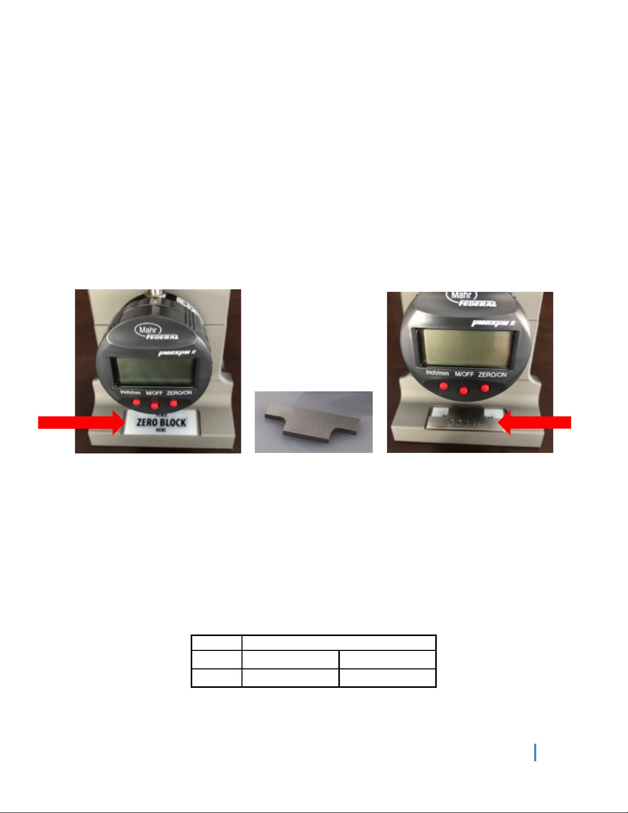
A!special!Zero!Block!(included)!will!set!the!digital!zero!reference.!
!
!
!
!
!
!
!
!
!
!
!
!
!
Environment!
The! indicator! is! built! to! withstand! severe! use.! It! has! a! gasket-sealed! case,! a! hard! crystal! display! window! and! a!
durable!stem! assembly! to! resist! most! dust! and! fluids.!The! gage! should! never! be! immersed! in! liquid!as! this! will!
cause! dam age! to! the! unit.! The! seals! and! boots! should!be!regularly!inspected!to! prevent! contamination.! The! dust!
cap!for!the! electronic! 4-pin!connector!should!always! be! in! place! whenever! an!output!cable!is! not! attached.! This!
will!prevent!damage!to!the!connector.!Please!respect!the!recommended!temperature!ranges!shown!below.!
!
!
!
!
!
!
!
!
Temperature!Range!
Storage:!
4°F!-!140°F!
-15.5°C!–!60°C!
Operation:!
60°F!-!90°F!
15.5°C!-!32°C!
The&magnet ic&base&secures&the&&
Zero&Block&for&easy&access&
The&Zero&Block&on&the&
&magnetic&base&
The&Zero&Block&&
Page 4

4!
Electronics!Inc.!•!(574)!256-5001!•!www.electronics-inc.com!
!
Control!Features!
Three!red!control!buttons!on!the!display!perform!these!user!functions:!
• ZERO/ON:! Turns! the! un it! “ON”.! It! can! also! be! used! to! set! the! Spindle!
Starting!Position.! See! the ! “Trouble! Shooting! the! M odel! TSP- M”! section!for!
more!information!on!this!feature.!
• M/OFF:!This!button,!when!pushed!and!held!for!three!(3)!seconds,!turns!the!
unit!“OFF”.!!
• inch/mm:!Allows!the!selection!of!the!display!in!inches!or!millimeters.!
!
!
!
!
Quick!Switch!From!MM!to!Inch!
SAE!J442!requires!Almen! gage! indicators! to! have!a!resolution! of! 0.001! mm;!therefore,!the!TSP-M! Almen!Gage!is!
factory!set!to!display!0.000!mm,!with!a!0 .0 01 !m m!resolution.!
!
Pressing!the! inch/mm ! button,! changing! measurement! u nits! from! millimeters! to! inches,! results!in! a!five! (5) ! digit!
display!(0.00000!inch)!with!a!resolution!of!0.00005!inch.!
!
If!a!display!of!only!four!(4)!dig its !(0 .0 0 00 )!in !in c h es !is!p re fer red ,!u s e!th e !fo llo w in g !ste p s!t o !rep ro g ra m!the!indicator.!
1. Turn!on!the!TSP-M!by!pressing!ZERO/ON.!
2. Press!inch/mm!to!change!the!scale!to!inches!
3. Press!the!M/OFF!and!inch/mm!buttons!at!the!same!time!(M1!will!appear!on!the!bottom!left!of!the!display)!
4. Press!M/OFF!four!(4)!times!
5. Press!inch/mm!six!(6)!times!until!the!display!shows!0.0001!
6. Press!M/OFF!to!exit!the!programming!mode!
!
!
Factory!Default!Settings!
Indicator!Polarity!
The! indicator! should! be! in! the! Reverse! M easurement! Direction! mode! as! indicated! by! “R”! at! the! bottom! of! the!
display.!This!allows! for!positive!numbers!to!be!shown!on!the!display!as!the! indicator!extends!into! the!concave!arc!
of!the! Almen!strip.!If!the! “R”!is!not!shown,!see!the!“Trouble! Sh ooting! the! Model! TSP-M”!section!to!return!to! the!
Reverse!Measurement!Direction!Mode.!
!
Resolution!
Metric!mode!resolution!is!factory!set!to!three!(3)!decimal!places!(e.g.,!0.600!mm).!If!the!inch!mode!is!required,!the!
resolution! will! be! set!at! five! (5)! places!(e.g.,!0.00240!inch)!by! default.! See! the! “Quick! Switch! from! MM! to! Inch”!
section!above!to!change!the!resolution!to!only!four!(4)!places.!!
!
!
!
Red&control&buttons&
Page 5
Electronics!Inc.!•!(574)!256-5001!•!www.electronics-inc.com!
5!
!
The&small&side&of&the&Zero&Block&is&placed&
on&the&gage.&The&reading&is&0.000&mm.&
Measuring!the!Pre-Bow!of!a!New!(Unpeened)!Almen!Strip!
The!following!steps!should!be!performed!on!the!standard!Almen!strips!and!the!mini-strips.!
!
1. Push!the!ZERO/ON!button!to!turn!the!gage!“ON”.!
2. Place! the! Zero! Block! on! the! gage! with! the! indicator! tip! touching! the! small! side! of! the! block.! Push! the!
ZERO/ON!button!to!achieve!0.000!mm!in!the!display.!!
3. Place!a! new! (unpeened)! Almen! strip! onto! the! measurement! position.! Be ! sure! the! s trip ! touches! the! back!
posts!and!is!centered!between!the!end!posts.!!
4. Read!and!record!the!pre-bow!(also!called!flatness).!!
5. Turn!the!strip!over!and!measure! the!opposite!side.!If!the!reading!from!either!side!exceeds!the!specification!
value,!discard!the!strip.!(See!Table!1!for!common!examples!of!acceptable!pre-bow).!
!
!
!
!
!
!
!
!
!
!
!
Table!1.!Examples!of!common!industry!Almen!strip!requirements!for!maximum!pre-bow!of!unpeened!strip!
Specification!
Grade!
mm!
Inch!
AMS2432,!Shot!Peening,!Computer!Monitored!
A1-S™,!N1-S™!
±0.013!
±0.0005!
AMS2430,!Shot!Peening!
A-1™,!N-1™!
±0.025!
±0.0010!
J442,!Test!Strip,!Holder!and!Gage!for!Shot!Peening!
A-1™,!N-1™!
±0.025!
±0.0010!
MIL-S-13165!Shot!Peening!of!Metals!(Canceled)!
A-2™,!N-2™!
±0.038!
±0.0015!
An&unpeened&&
mini-strip&placed&on&
the&mini-strip&gage.&
An&unpeened&&
Standard&Almen&
strip&placed&on&the&
#2&Almen&gage.
&
Page 6

6!
Electronics!Inc.!•!(574)!256-5001!•!www.electronics-inc.com!
!
Measuring!the!Arc!Height!of!a!Peened!Almen!Strip!
The!following!steps!should!be!performed!on!the!standard!Almen!strips!and!the!mini-strips.!
!
Step!One!–!Zero!the!Almen!Gage!
1. Push!the!ZERO/ON!button!to!turn!the!gage!“ON”.!!
2. Place! the! Zero! Block! on! the! gage! with! the! indicator! tip! touching!
the!small!side.!Push!the!ZERO/ON ! b u tto n! to! a ch ie ve ! 0 .00 0 ! mm!in!
the!display.!
!
Step!Two!–!Perform!Pre-Bow!Compensation!
If!your! shot! peening! pro c edure,! such!as!process! development! o r! system!
capability! studies,! requires! higher! intensity! accuracy,! pre-bow!
compensation! may! be! used.! This! technique! can! provide! an! additional!
reduction! in! process! uncertainty.! A ! pre-bow! compensation!ensures! that!
only!the!net!difference!in!arc!height!of!a! peened!Almen!strip!is!plotted!on!
a!saturation!curve.!To!perform!pre-bow!compensation:!
1. Zero! the!Almen!gage!and!then!place!the! unpeen ed!Almen!strip!on!
the!gage!and!record!its!value.!!
2. Be!sure!to!note!if!value!is!positive!or!negative!and!write!the!value!
on!the!opposite!side!of!the!strip.!!
3. Do! not! peen! the! side! of! the! Almen! strip! with! your! handwritten!
note.!!
4. A!positive! num ber! is!subtracted! from! the! arc!height!reading!
after!the!strip!has!been!peened.!A!negative!num ber! is!added!
to! the! arc! height! reading! after! the! strip! has! been! peened.!
For!example:!
a) If!the! pre-bow! is!+2! and! the! arc! height!reading! is! 10,!
the!adjusted!arc!height!reading!is!8!
b) If!the! pre-bow! is! -2! and! the! arc! height! reading! is! 10,!
the!adjusted!arc!height!reading!is!12!
!
In! summary,! most! pee n in g ! a p p lica tio n s ! ca n ! t o ler at e! t h e! S A E! J442!
pre-bow!bias! of!±0.001”!for! N ! and! A!strips.!If!this!tolerance! level! is!
too! high,! you! can! apply! the! pre-bow! compensation! discussed!
above.!!
!
Step!Three!–!Measure!the!Arc!Height!
1. Place! the!peened! Almen! strip! onto! the! measurement! position! with!
the!indicator! tip!touching!the!non-peened! side!(concave!side)!of!the!
strip.!Record! the!value! of!the! arc!height! shown! in! the! display! or,! if! using! pre-bow! compensation,! th e! arc!
height!shown!in!the!display!with!the!pre-bow!compensation!applied.!
2. Remove!the!strip!and!place!it!once!again!on!the!gage.!Do!this!three!(3)!times!to!assure!an!accurate!reading.!!
3. When!finished,!push!and!hold!the! M/OFF! button!for! three!(3)!seconds!to! turn! the!gage!“OFF”.!(The! gage!
automatically!turns!“OFF”!if!it!is!not!active!for!15!minutes.)!
!
!
Peened&mini-strip&placed&on&the&mini-
strip&gage.&The&reading&is&0.199&mm.&
Peened&standard&Almen&strip&placed&
on&the&Almen&gage.&
Page 7
Electronics!Inc.!•!(574)!256-5001!•!www.electronics-inc.com!
7!
!
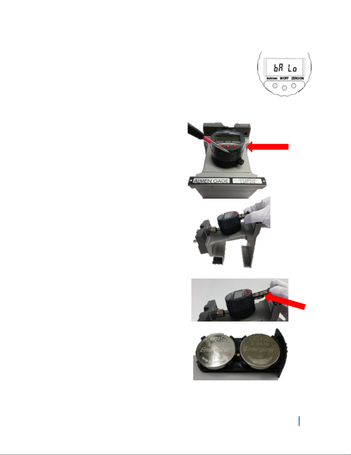
Battery&Low&message&
Changing!the!Batteries!
The! Almen! gage! has! a! battery! tray! that! holds! two! (2)! CR2450! lithium! batteries.! A!
warning!message!appears!in!the!gage’s!display!when!the!batteries!need!to!be!replaced.!!
!
!
!
!
!
To!change!the!batteries:!
!
!
!
!
!
!
!
!
!!
!
!
!
!
!
The!batteries!are!on!the!underside!of!the!tray.!!
!
!
!
!
!
!
Step!3.!Remove!the!expired!batteries!and!place!the!new!!
batteries!positive!side!up!in!the!tray.!(The!current!Almen!!
gage!set-up!and!calibration!information!are!retained!when!!
the!batteries!are!replaced.)!Place!the!battery!holder!in!!
the!battery!compartment!and!push!it!in!until!it!locks!into!!
position.!
!!
!
!
Step!1.!Using!a!small!flat-blade!screwdriver,!carefully!
slide!the!blade!into!the!opening!and! release!the!
battery!holder.!Do!NOT!remove!digital!indicator!from!
the!gage.!
!
Step!2.!Once!the!battery!holder!is!unlocked,!grasp!it!
with!your!fingers!and!pull!the!battery!holder!out.!
!
Do!NOT!remove!the!digital!
indicator!from!the!gage!
!
Page 8
8!
Electronics!Inc.!•!(574)!256-5001!•!www.electronics-inc.com!
!
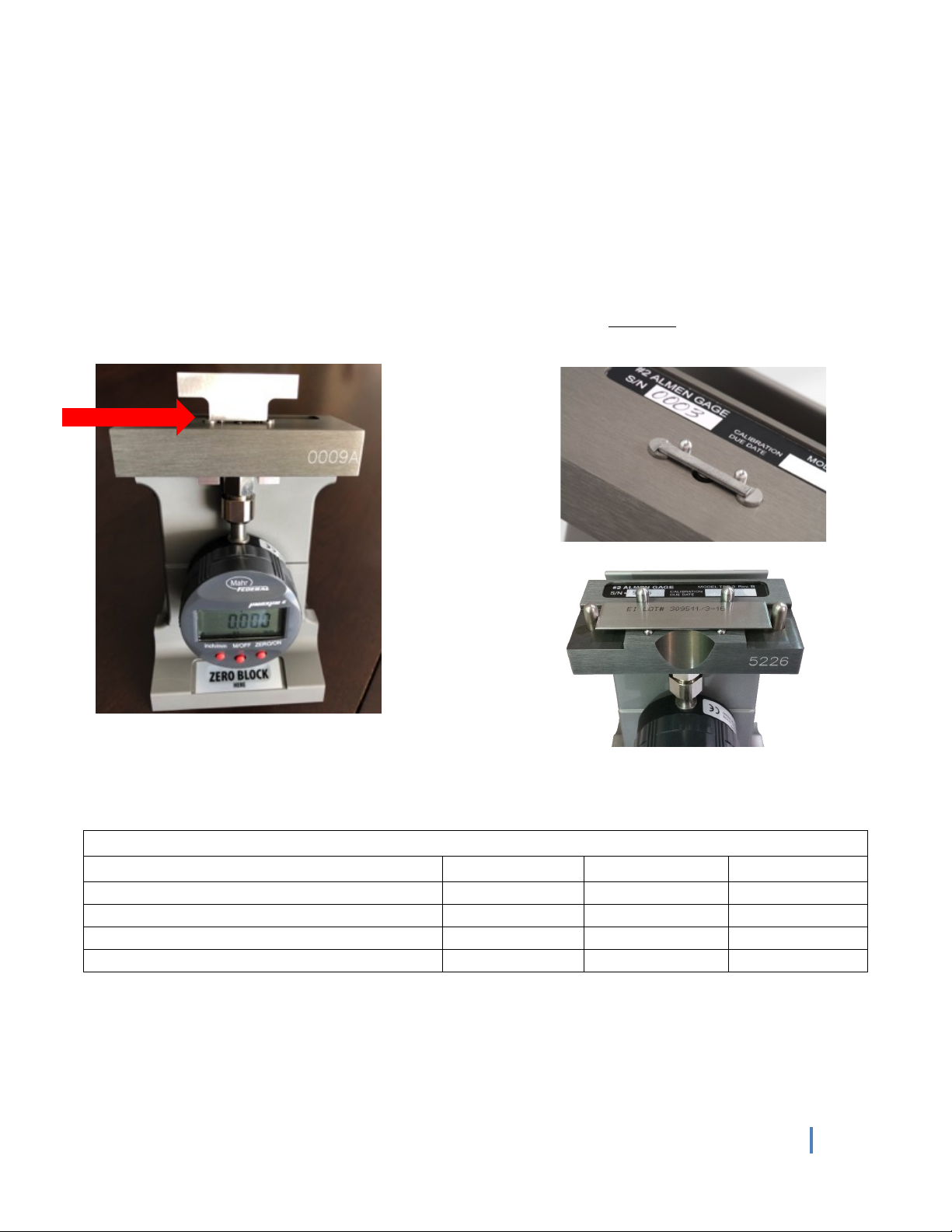
Calibration!
Periodic! calibration! of! the! Almen! gage! is! important! to! assure!
process!repeatability!and!accuracy.!The! gage’s!digital! indicator!
should! be! removed! and! calibrated! annually! or! sooner! if! it!
appears! to! be! damaged! or! inaccurate.! Use! of! a! standard!
calibration!stand!as!shown !is! recom m end ed!or!you!may! return!
the!gage!to!Electronics!Incorporated!for!service.!!
!
The! digital! indicator!should!be!re-installed! with ! t h e! Zero!Block!
in!place! and ! the!physical! position!of! th e ! indicator! adjuste d ! on!
the! fram e! so! that! it! is!near!True!Spindle! Zero! ±0.025! mm.! This!
assures! that! the! indicator! is! in! the! preferred! accuracy! range.!
!See!the!section!titled!“Checking! or!Setting!the! Sp indle! Starting!
Position”!for!more!information.!
!
!
!
!
!
Inspection!of!the!Gage!Head!
Examine!the!condition!of! the! back!post!for!wear,! which!may!
interfere!with!proper!seating !o f!th e !strip !o n to !t h e!p la tfo rm.!!
!
!
!
!
!
!
!
!
!
!
!
!
!
!
!
!
Federal&Calibration&Stand&
Page 9

Electronics!Inc.!•!(574)!256-5001!•!www.electronics-inc.com!
9!
!
Digital!Indicator!Instruction!Manual!Information!
For!additional!information!on!the! digital!indicator,!please!refer!to!the!Mahr!Federal!Incorporated!Digital!Indicator!
Manual!included!with!the!gage.!If!missing,!the!manual!is!available!from!Electronics!Inc.!
!
!
!
!
!
!
!
!
!
!
!
Computer!Interface!Device!Accessory!
Entering! multiple! measurements! is! quick! and! easy! with! the!
Computer!Interface! Device.! The!device! plugs! into! a! computer’s!
USB! port! and! pulls! the! value! displayed! on! the ! Ele ctron ics!
Incorporated! Almen! Gage!directly! into! a! computer! program!
(Excel,! Word,! or! similar! software).! The! Computer! Interface!
Device! eliminates! data! entry! errors! and! accelerates! the!
measurement!process.!A!push-button!or!foot!switch!controls!the!
device.! Th ere ! are! no! power! requirements! as! the! device! is!
powered!from!the!USB!port!and!there!are!no!d rive rs!to!lo ad.!!
!
!
!
!
!
!
Cover&page&of&the&instruction&manual&for&the&Digital&Indicator&
The&Computer&Interface &Device&&
(part&number&999144)&&
(Does¬&include&an&Almen&gage)&
Page 10

10!
Electronics!Inc.!•!(574)!256-5001!•!www.electronics-inc.com!
!
Trouble!Shooting!the!Model!TSP-M!
If!the! TSP-M! Almen! Gage! indicator! displa y! is! fla sh in g ,! or! if! the! g a ge ! will! n o t! zero,! or!the! resolution! needs! to! be!
changed,! the! following! instructions! will! return! the! gage! back! to! its! factory! default! settings! and! remedy! these!
conditions.!Perform!every!step—one!through!six—in ! sequen c e! until! the!problem! is!resolved.!If!more!assistance!is!
needed,!please!call!Electronics!Incorporated!Customer!Service!Department!at! 1-800-832-5653! (USA!and!Canada)!
or!(574)!256-5001.!
!
Step!One!
• Press!M/OFF!and!the!inch/mm!button!at!the!same!time.!"M1"!will!appear!on!the!screen.!
• If!the!"R"!is!not!on!the!botto m!left!side!of!the!screen,!pre ss !Z E R O / O N !b u tt o n !u n til!th e !“R ” !is !o n !th e !sc re e n .!
• If!the!"X1"!is!not!on!the!bo tto m!center!of!the!screen,!pre ss !th e !in ch / mm!button!until!“X1”!is!se le c te d .!
!
Step!Two!
Press!M/OFF!button.!"M2"!will!appear!on!the!screen!and!it!should!read!000.0000.!
• If!“-“!precedes!the!digits,!press!the!ZERO/ON!button!to!remove!it.!
• Press!the!inch/mm!button!to!move!the!cursor!over!to!the!first!non-zero!digit!to!be!changed.!
• Press!the!ZERO/ON!button!repeatedly!to!toggle!through!numbers!until!“0”!is!displayed.!Repeat!for!!other!
!digits!not!at!“0.”!
!
Step!Three!
Press!M/OFF!button.!"M12"!will!appear!on!the!screen!and!it!should!read!000.0000.!
• If!“-“!precedes!the!digits,!press!the!ZERO/ON!button!to!remove!it.!
• Press!the!inch/mm!button!to!move!a!cursor!over!to!the!first!non-zero!digit!to!be!changed.!
• Press!the!ZERO/ON!button!repeatedly!to!toggle!through!numbers!until!“0”!is!displayed.!Repeat!for! o ther!
digits!!not!at!“0.”!
!
Step!Four!
Press!M/OFF!button.!"M23"!will!appear!on!the!screen!and!it!should!read!000.0000.!
• If!“-“!precedes!the!digits,!press!the!ZERO/ON!to!remove!it.!
• Press!the!inch/mm!button!to!move!a!cursor!over!to!the!first!non-zero!digit!to!be!changed.!
• Press!the!ZERO/ON!button!repeatedly!to!toggle!through!numbers! until!“0”! is!displayed.!Repeat!for!other!
digits!!not!at!“0.”!
!
Step!Five!
• Press!M/OFF!button.!"M13"!will!appear!on!the!screen.!This!is!the!Digital!Resolution!Mode!screen.!
• When!using!the!mm!mode!–!press!the!inch/mm!button!repeatedly!to!select!0.001.!
• When!using!the!inch!mode!–!press!the!inch/mm!button!repeatedly!to!select!0.0001.!
!
Step!Six!
• Press!M/OFF!button!-!the!gage!will!be!in!run!mode.!
• Place!the!flat!side!of!the!curved!Zero!block!on!top!of!gage!and!press!the!ZERO/ON!button.!
• The!indicator!will!read!0.000!mm!if!in!metric!mode!or!0.000 0 !if!in !E n glis h !m o d e .!
• The!bottom!of!the!screen!will!read!"R!X1!mm"!or!"R!X1!in".!
!
Step!Seven!
Check!the! Spindle! Starting!Position! to! ensure!it! is! in!the! preferred!range.!See! the! next! section! for!directions!on!
checking!or!setting!the!Spindle!Starting!Position.!
!
!
!
Page 11

Electronics!Inc.!•!(574)!256-5001!•!www.electronics-inc.com!
11!
!
Checking!or!Setting!the!Spindle!Starting!Position!
To!evaluate!the!Spindle!Starting!Position,!place!the!Zero!Block! on! the!gage! and! enter!the!gage!into!True! Spindle!
Mode! by! pressing!and! holding!the!ZERO/ON! button!for! three! (3)!seconds! (the! “X1”! will! disappear! when! in! True!
Spindle! M ode).! The! value! o f! the! Spindle! Starting! Position! should! be! set! to! 0.000! m m! +!0.025!mm!(0.0000!inch!+!
0.0010!inch).! If! the!Spindle! Starting! Position!is! out! of! tolerance,! reposition!the! indicator! on! the! frame! using!the!
instructions!below!or!call!Ele c tro n ics !In co rp o r at ed !o r!a n !A u th o riz ed !D is trib u to r!f or !as sis ta n ce .!
!
Instructions:!
Be!sure! the!zero!indicator!block! is!in!place! and! then! loosen!the!8!mm!gland! nut! holding!the!indicator.!Adjust!the!
indicator!placem e nt !on!the!frame!until!the!Spindle!Starting!Pos itio n !is!within!tolerance.!Care fu lly !tighten!the!gland!
nut!and!be!sure!the!indicator!is!secure.!It!s ho u ld ! not!move!or!rotate,!and!the!Spindle!Starting!Position!sho uld! not!
change!as! the! gland!nut! is! tightened.!Place!a! dab! of!proof! lacquer! at!the! gland! nut! and!stem! as! a!tamper-proof!
seal.!
!
!
!
Contacting!Electronics!Inc.!
Mailing!and!Shipping!Address:!
Electronics!Inc.!
56790!Magnetic!Drive!
Mishawaka,!IN!46545!USA!
!
Telephone:!1-800-832-5653!(Toll-free!in!USA!and!Canada)!or!(574)!25 6-5001!
Fax:!(574)!256-5222!
Email:!sales@electronics-inc.com!
Website:!www.electronics-inc.com!
!
!
!
!
!
!
!
!
!
!
!
!
!
!
!
!
!
Page 12

12!
Electronics!Inc.!•!(574)!256-5001!•!www.electronics-inc.com!
!
Limited!Warranty!
The!warranty!obligations!of!Electronics!Inc.!for!the!TSP-M!are!limited!to!the!terms!set!forth!below.!
!
Length!of!Warranty!Period!
This! limited! warranty! lasts! one! (1)! year! from! the! shipping! date! of! this! p roduct! from! Electronics! Inc.! or! its!
authorized!distributor.!
!
What!is!Covered!
This!limited!warranty!covers!defects!in!materials!and!workmanship!in!this!produ c t.!
!
What!is!Not!Covered!
This!limited!warranty!does!not! cover!any!damage!or!deterioration!of!this!product!resulting!from!any!alteration! or!
modification,!improper!or!unreasonable!use!or!maintenance,!or!improper!handling!or!storage.!
!
How!to!Obtain!a!Remedy!Under!This!Limited!Warranty!
To!obtain!a!remedy!under!this!limited!warranty,!contact!Electronics!Inc.!or!distributor!from!whom!this!product!was!
purchased.!If! it! is! determined! that! this!product!must!be! returned!under!this! limited! w arra nty,! a!Returned!Goods!
number!(RG),!obtained!from!Electronics!Inc.,!will!be! required.!This!product!should!be! properly!packed,!preferably!
in! the! original! carton,! fo r! shipping.! Cartons! not! b e ar in g! a! RG! number! will! require! additional! processing! time.!
Shipping!and!insurance!charges!must!be!prepaid;!Electronics!Inc.!is!not!responsible!for!these!expenses.!
!
What!Electronics!Inc.!Will!Do!Under!This!Limited!Warranty!!
Electronics!Inc.!will,!at! its! sole!discretion,!provide! one! of!the! following! two!remedies!to!whatever!extent! it! shall!
deem!necessary!to!satisfy!a!proper!claim!under!this!limited!warranty:!
!
1)!Repair!the!product.!Electronics! Inc.!will!pay!the!shipping!costs!necessary!to!return!this! product!to!the!customer!
once!the!repair!is!complete.!
!
2)!Replace!this!product!with!a!comparable! current!model.!Electronics!Inc.!will!pay!the!shipping! costs!necessary!to!
replace!this!product.!
!
Limitation!on!Liability!
The! maximum! liability! of! Electronics!Inc.! under! this! limited!warranty! shall!not! exceed! the! actual! purchase! price!
paid! for! the! product.! Electronics! Inc.! is! not! responsible!for! direct,! special,! incidental! or! consequential! damages!
resulting! from ! any! breach! of! warranty ! or! condition,! or! under! any! other! le gal! theory! to! the! maximu m ! extent!
permitted!by!law.!
!
Exclusive!Remedy!!
To!the! maximum! extent!permitted! by! law,!this! limited! warranty!and! the! remedies!set! forth! above!are! exclusive!
and!in! lieu! of!all! other! warranties,!remedies!and! cond itions,! whether!oral! or! written,!express! or! im plied.! To!the!
maximum!extent!permitted!by!law,!Electronics!Inc.! specifically! disclaims!any! and!all! implied!warranties,!including,!
without! limitation,! warranties! of! merchantability! and! fitness! for! a! particular!purpose.! If! Electronics! Inc.! cannot!
lawfully! disclaim! or! exclude! implied! warranties! under! applicable! law,! then! all! implied! warranties! covering! this!
product,!including!warranties!of! m erchantability!and!fitness!for!a!particular!purpose,!shall!apply!to!this! product!as!
provided!under!applicable!law.!!
!
Rights!under!State!Law!
This! warranty!defines! specific!legal! rights!relative!to! these!products! provided!by!Electronics!Inc.!Legal!rights!may!
also!vary!from!state!to!state.!
!
!
!
!
Page 13

Electronics!Inc.!•!(574)!256-5001!•!www.electronics-inc.com!
13!
!
Appendix!
Introduction!to!Correlation!
Almen! mini-strips! must! be! compared! to! standard-size! Almen! strips! to! assure! compliance! with! intensity!
measurement!practices.!The!comparisons!are!described!in!correlation!trials!where!the!standard!Almen!strip!is!used!
to!set!the!requested!intensity!and!the!mini-strip!is!presented!to!the!same!blast!stream.!It!is!important!to!document!
the! test! results,! especially! the! parameters! and! all! test! conditions.! Testing! multiple! strips! and! the ! creation! of! a !
histogram!can!help!validate!the!process.!!
!
The!Almen!Strips!and!Correlation!Holder!
It! is! convenient! to! peen! the! standard-size! Almen! strip! and! the! mini-strip! at! the! same! time! using! a! correlation!
holder.!There!are!two!methods!of!affixing!the!mini-strip!to!the!co rrelation!holder.!In!the!first!m e th o d ,!two!screws!
secure! the! ends! of! the! mini-strip.! For! the! second! method,! double-sided! adhesive! tape! or! a! temp orary ! glue!
adhesive,!such!as!rubber!cement,!secures!the! mini-strip!to!the! ho lder.! The!second!method! is!used!only! when!it!is!
not!possible!to!attach!the!mini-strip!to!the!holder!with!two!screws.!!
!
For!both!methods,!the!standard!Almen!strip!must!be!affixed!to!the!holder!with!four!screws.!
!
The!first!image!belo w!shows!the!metho d! u sing! tw o!hold-down!screws!to!secure!the!mini-strip!to! the!EI!Correlation!
Holder!for!mini-strips!(Electronics!Inc.! part! number! 970 070).! The!strip!is!positioned! next!to!two! protruding ! b ac k-!
stops!to!help!keep!it!aligned.!In!the!second!image,!the!mini-strip!is!attached!to!the!holder!with!double-sided!tape.!
!
!
!
!
!
It!is!very!important! to ! u s e ! only!one!method.! The!two!hold-dow n!screws!w ill!keep!the!strip!firmly!secured!to!the!
holder! during! the! blast! cycle! while! the! tape! or! glue! may! allow! some! lift-off! or! curvature.! This! curvature! may!
influence! the! mini! strip! resp o n se .! As! long! as! the! technique! is! consistent,! the! results! should! be! consistent.! A!
sufficient!number!of! trials!should!be!run! to!validate! the!procedure.!The!examples!shown!in!the!next!se ction ! titled!
“Examples!of!Correlation”!use!multiple!trials!and!the!data!is!shown!in!a!statistical!capability!chart!(histogram).!!
!
When!in!doubt,!run!more!tests!and!analyze!the!data!carefully.!!!
!
Note:!When!using!tape! or! glue!to!affix!the!mini-strip!to!the! holder,! m ake! sure!the!tape! and! glue ! are!completely!
removed!from!the!holder!and!strip!before !me asu rin g!the !strip!or!reu sing !the!h old er.!
Two&screws&holding&a&mini-strip&in&place&
A&mini-strip&held&in&place&with&double-sided&tape.&This&
method& should& be& used& only& when& the& mini-strip&
cannot&be&attached&to&the&holder&with&screws.&&
Page 14

14!
Electronics!Inc.!•!(574)!256-5001!•!www.electronics-inc.com!
!
Examples!of!Correlation!
The!following! examples!of! correlation!between!standard- size!Almen!strips!and!mini-strips!are!for!illustration! on ly.!
Actual!correlation! must!always!be! done!on!a!job-specific!ba sis.! The!special!Almen!holder!for!co rrelation! uses!two!
screws!to! capture! the! mini-strip.! Other!methods! may! be! used!such! as! double-sided! tap e! or! temporary! adhesive!
(e.g.,!rubber!cement).!For!best!results,!all!procedures!must!be!consistent.!When!in!doubt,!repeat!a!test.!!
!
!
Test!
Standard!Strip!
x!.001!inch!
Mini!Strip!
x!.001!inch!
Graph!1!
3A!to!A!mini!(36)!samples!test!2!
3.26!A!
1.15!Mini!A!
Graph!2!
3A!to!A!mini!(36)!samples!
3.25!A!
1.25!Mini!A!
Graph!3!
3A!to!A!Mini!2!tests!
3.5!A!
3.26!A!
1.25!Mini!A!
1.15!Mini!A!
Graph!4!
6A!to!A!Mini!2!tests!
5.79!A!
5.95!A!
2.40!Mini!A!
2.46!Mini!A!
Graph!5!
6A!to!A!Mini!Test!2!
5.95!A!
2.46!Mini!A!
Graph!6!
6A!to!A!Mini!
6.09!
2.40!Mini!A!
Graph!7!
12A!to!A!Mini!and!N!Mini!
12.08!A!
5.68!Mini!A!
18.40!Mini!N!
Graph!8!
12A!to!A!Mini!
12.32!A!
4.93!Mini!A!
Graph!9!
12A!to!A!Mini!
12.08!A!
5.68!Mini!A!
!
!
!
Note:!These!examples!are!for!illustration!only.!Differences!in!m ac h ine !design,!nozzle!type !and!placement,!typ e !and!
size!of!media,!and!media!condition!can!affect!results.!Document!what!you!do!and!do!what!you! documen t.!When! in!
doubt,!repeat!a!test.!Keep!accurate!records!of!every!te st.!Use!a!cu rve !solver!certified! to !SAE!J2597.!Place!the!m in i-
strip!on!the!gage!multiple!times!to!assure!the!reading!is!consistent.! !
!
Do! not! rely! upon! these! examples.! We! do! not! warrant! that! these! examples! will! be! appropriate! for! your!
applications.!Create!your!own!correlation!studies.!!
!
!
!
!
!
!
!
!
!
!
!
!
!
!
Page 15

Electronics!Inc.!•!(574)!256-5001!•!www.electronics-inc.com!
15!
!
Graph!1!-!3.26!A!to!1.15!Mini!A!
!
!
!
!
!
!
!
!
!
!
!
!
!
!
!
!
!
!
!
!
!
!
!
!
!
!
!
!
!
!
! !
!
!
!
!
!
!
!
!
!
!
!
!
!
Page 16

16!
Electronics!Inc.!•!(574)!256-5001!•!www.electronics-inc.com!
!
Graph!2!-!3.25!A!to!1.25!Mini!A!
!
!
!
!
!
!
!
!
!
!
!
!
!
!
!
!
!
!
!
!
!
!
!
!
!
!
!
!
!
!
!
!
!
!
!
!
!
!
!
!
!
!
!
!
!
Page 17

Electronics!Inc.!•!(574)!256-5001!•!www.electronics-inc.com!
17!
!
Graph!3!–!3.5!A!to!1.25!Mini!A,!3.26!A!to!1.15!Mini!A!
!
!
!
!
!
!
!
!
!
!
!
!
!
!
!
!
!
!
!
!
!
!
!
!
!
!
!
!
!
!
!
!
!
!
!
!
!
!
!
!
!
!
!
!
!
!
Page 18

18!
Electronics!Inc.!•!(574)!256-5001!•!www.electronics-inc.com!
!
Graph!4!-!5.79!A!to!2.40!Mini!A,!5.95!A!to!2.46!Mini!A!
!
!
!
!
!
!
!
!
!
!
!
!
!
!
!
!
!
!
!
!
!
!
!
!
!
!
!
!
!
!
!
!
!
!
!
!
!
!
!
!
!
!
!
!
!
!
Page 19

Electronics!Inc.!•!(574)!256-5001!•!www.electronics-inc.com!
19!
!
Graph!5!-!5.95!A!to!2.46!Mini!A!
!
!
!
Page 20

20!
Electronics!Inc.!•!(574)!256-5001!•!www.electronics-inc.com!
!
Graph!6!-!6.09!A!to!2.40!Mini!A!
!
!
!
!
!
!
!
!
!
!
!
!
!
!
!
!
!
!
!
!
!
!
!
!
!
!
!
!
!
!
!
!
!
!
!
!
!
!
Page 21

Electronics!Inc.!•!(574)!256-5001!•!www.electronics-inc.com!
21!
!
!
Graph!7!-!12.08!A!to!5.68!Mini!A,!18.40!Mini!N!
!
!
!
!
!
!
!
!
!
!
!
!
!
!
!
!
!
!
!
!
!
!
!
!
!
!
!
!
!
!
!
!
!
!
!
!
!
!
!
!
!
!
!
!
Page 22

22!
Electronics!Inc.!•!(574)!256-5001!•!www.electronics-inc.com!
!
Graph!8!-!12.32!A!to!4.93!Mini!A!
!
!
!
!
!
!
!
!
!
!
!
!
!
!
!
!
!
!
!
!
!
!
!
!
!
!
!
!
!
!
!
!
!
!
!
!
!
!
!
!
!
!
!
!
!
!
Page 23

Electronics!Inc.!•!(574)!256-5001!•!www.electronics-inc.com!
23!
!
Graph!9!-!12.08!A!to!5.68!Mini!A!
!
!
!
!
!
!
!
!
!
!
!
!
!
!
!
!
!
!
!
!
!
!
!
!
!
!
!
!
!
!
!
!
!
!
!
!
!
!
!
!
!
!
!
!
!
!
Page 24

24!
Electronics!Inc.!•!(574)!256-5001!•!www.electronics-inc.com!
!
Compilation!of!Correlation!Data!
The! following! graph! com pares! the! performance! of! the! standard! “A”! strip! to! the! “A”! mini-strip! based! on! the!
previous!graphs.!The! examples! shown! in! this! document! are! included! for! educational!purposes! only.!Do! not! rely!
upon!this!data.!We!do!not!wa rra nt !that!these!examples!w ill!be!appropriate !for!your!applications.!Create!your!own!
correlation!studies.!!
!
!
!
!
!
!
0.00!
2.00!
4.00!
6.00!
8.00!
10.00!
12.00!
14.00!
0.00! 5.00! 10.00! 15.00! 20.00! 25.00!
Mini-A!Strip!
Standard!A!Strip!
Correlation!A!to!Mini-A!
Arc!Height!x!.001inch!
 Loading...