

Page 1

Smart Engine Analyzer
(SR-8A)
Operating and Installation Instructions
OI 020481 and II 012881
1/28/88
Rev. C: 2/2/93 *
You must read this manual before installing or operating the instrument.
S0210921
Model:
S/N:
Electronics International Inc. ®
63296 Powell Butte Highway Bend OR 97701 (541) 318-6060
Page 2
Important Notice
***** MUST READ *****
If you think it is not important to read this manual, you're wrong! This manual
contains important installation information that may affect the safety of your aircraft, delay your installation or affect the operation of your instrument. You
read this manual prior to installing your instrument. Any deviation from these
installation instructions is the sole responsibility of the installer/pilot and may
render the STC invalid.
Read the Warranty / Agreement. There is information in the Warranty / Agreement that may alter
your decision to install this product. If you do not accept the terms of the Warranty / Agreement, do not
install this product. This product may be returned for a refund. Contact Electronics International inc. for
details.
Check that the instrument make and model marked on the side of the instrument and on the invoice are
correct before starting the installation.
Must
It is possible for any instrument to fail thereby displaying inaccurate high, low or jumpy readings.
Therefore, you must be able to recognize an instrument failure and you must be proficient in operating your
aircraft safely in spite of an instrument failure. If you do not have this knowledge, contact the FAA or a
local flight instructor for training.
The ability for this product to detect a problem is directly related to the pilots interpretation and
observation skills.
The pilot
to operate the aircraft that does not know the operation of this product. Keep the Operating Manual in the
aircraft at all times.
must understand the operation of this product before flying the aircraft. Do not allow anyone
Page 3

Contents
Warranty ------------------------------------------------------------------------------ 2
Operating Instructions: ------------------------------------------------------------ 3
Introduction ---------------------------------------------------------------------------------- 3
Features --------------------------------------------------------------------------------------- 3
Operating The Smart Analyzer in Your Aircraft ---------------------------------------- 6
Installation Instructions: ----------------------------------------------------------- 9
1. Important Information and Initial Check Out -------------------------------------------- 9
2. Instrument Setup ------------------------------------------------------------------------ 9.5
3. CHT Probe Installation ----------------------------------------------------------------- 10
4. EGT Probe Installation ----------------------------------------------------------------- 11
5. TIT Probe Installation ------------------------------------------------------------------ 11
6. Oil Temperature Probe Installation --------------------------------------------------- 11
7. Carb. Temp. Probe Installation -------------------------------------------------------- 12
8. OAT Probe Installation ---------------------------------------------------------------- 12
9. Mark Each Extension Cable ----------------------------------------------------------- 12
10. Route The Circular Connector ------------------------------------------------------- 13
11. Route Each Extension Cable ---------------------------------------------------------- 13
12. Hook Up Connecting Wires ----------------------------------------------------------- 15
13. Instrument Installation ----------------------------------------------------------------- 15
14. System Ground Test -------------------------------------------------------------------- 15
Troubleshooting Suggestions ------------------------------------------------------ 16
Specifications and Operating Features ----------------------------------------- 18
SR-8A Wiring Diagram ------------------------------------------------------------19
SR-8A Sample Wiring Diagram For Single 6-Cylinder Engine Aircraft - 20
Appendix A - Adding a Channel to the SR-8A -------------------------------- 21
Appendix B - SR-8A Circular Connectors ------------------------------------- 22
STC Information --------------------------------------------------------------------23
1
Page 4

Warranty
1209921
Electronics International Inc. warrants this instrument and system components to be free from defects in
materials and workmanship for a period of one year from the user invoice date. Electronics International Inc. will repair or replace any item under the terms of this Warranty provided the item is returned
to the factory prepaid.
l. This Warranty shall not apply to any product that has been repaired or altered by any person other
than Electronics International Inc., or that has been subjected to misuse, accident, incorrect wiring,
negligence, improper or unprofessional assembly or improper installation by any person. This warranty
does not cover any reimbursement for any persons time for installation, removal, assembly or repair.
Electronics International retains the right to determine the reason or cause for warranty repair.
2. This warranty does not extend to any machine, vehicle, boat, aircraft or any other device to which the
Electronics International Inc. product may be connected, attached, interconnected or used in conjunction
with in any way.
3. The obligation assumed by Electronics International Inc. under this warranty is limited to repair,
replacement or refund of the product, at the sole discretion of Electronics International Inc.
4. Electronics International Inc. is not responsible for shipping charges or damages incurred under this
Warranty.
5. No representative is authorized to assume any other liability for Electronics International Inc. in
connection with the sale of Electronics International Inc. products.
6. If you do not agree to and accept the terms of this warranty, you may return the product in new
condition, with receipt, within thirty (30) days for a refund.
This Warranty is made only to the original user. THIS WARRANTY IS IN LIEU OF ALL OTHER
WARRANTIES OR OBLIGATIONS: EXPRESS OR IMPLIED. MANUFACTURER EXPRESSLY
DISCLAIMS ALL IMPLIED WARRANTIES OF MERCHANTABILITY OR FITNESS FOR A
PARTICULAR PURPOSE. PURCHASER AGREES THAT IN NO EVENT SHALL MANUFACTURER BE LIABLE FOR SPECIAL, INCIDENTAL OR CONSEQUENTIAL DAMAGES, INCLUDING LOST PROFITS OR LOSS OF USE OR OTHER ECONOMIC LOSS. EXCEPT AS
EXPRESSLY PROVIDED HEREIN, MANUFACTURER DISCLAIMS ALL OTHER LIABILITY
TO PURCHASER OR ANY OTHER PERSON IN CONNECTION WITH THE USE OR PERFORMANCE OF MANUFACTURERS PRODUCTS, INCLUDING SPECIFICALLY LIABILITY IN
TORT.
.
2
Page 5
SR-8
OPERATING INSTRUCTIONS
OI 020481
Rev: A 2/10/92
The Smart Analyzer is easy to operate. You can learn the basic operation of this unit in the first few minutes of
hands-on operation. Although the Smart Analyzer is simple to operate, its capabilities are numerous. The following section will describe the operating features of the Smart Analyzer and some of its capabilities.
Features
1. Multi-Function Capability:
The Smart Analyzer has 8 channels. For a 6-cylinder engine, the first 6 channels should be used for EGT or
CHT engine analysis. These channels are designated as "Analyzer Channels". The Peak Locate, Hottest
Cylinder Indicator and Differential Warning features are only functional on the analyzer channels. The EGT
Overtemp and Lowtemp, TIT Overtemp and Lowtemp, and the CHT Overtemp features are functional on all
channels. The Smart Analyzer knows which channels are TIT, EGT and CHT regardless of how it is hooked
up.
Any channel on the Smart Analyzer may be used to measure any temperature (EGT, CHT, TIT, Oil, OAT,
Carb, Induction Air, Cabin Air, Cowling Air, Water, Intercooler, etc.).
3
Page 6

A set of switches on the back of the Smart Analyzer allows the unit to be set up for a 4 or 6-cylinder engine,
fuel-injected or carbureted engine and to scan 6 or 8 channels (see Installation Instructions for more information).
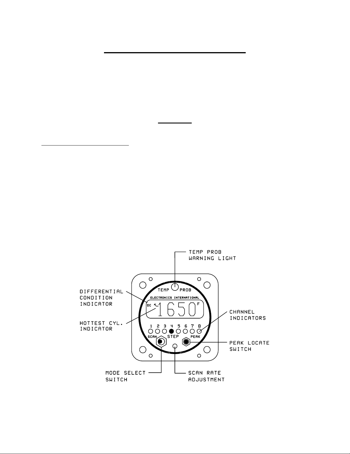
2. Mode Select Switch:
A) Manual Mode - With the Mode Select Switch in the center position, the Smart Analyzer will display the
temperature on the channel designated by the green Channel Indicators.
B) Step Position - When the Mode Select Switch is pressed to the right, the Smart Analyzer will advance to
the next channel. When this switch is released, it will return to the center position (Manual Mode). The
Smart Analyzer can be set up to step through 6 or 8 channels from the back panel (see Installation Instructions).
C) Scan Mode - In the Scan Mode, the Smart Analyzer will automatically scan through the channels. When
the unit is first placed into the Scan Mode, it will switch to Channel One to start its scan. This is done to
establish a reference for the automatic engine analysis features.
FeaturesOperating Instructions
The Smart Analyzer may be placed in the Scan Mode during runup, takeoff, climb or cruise, as long as the
engine temperatures are increasing or stable. This unique operating characteristic allows the Smart Analyzer
to stand watch over your engine during most phases of a flight. But if the engine temperatures are decreasing
or low (as they would be at idle), the Smart Analyzer should be placed into the Manual Mode of operation to
eliminate any false Low limit or Differential Condition problems it may find. Generally this only happens
when the throttle is decreased or you are operating at low throttle settings.
3. Hottest Cylinder Indicator:
In the Scan Mode, an arrow will appear in the display any time the Smart Analyzer is displaying the hottest
analyzer cylinder. This feature allows you to determine if the leanest cylinder has changed. If this happens,
you may need to readjust your mixture.
4. "Temp Prob" Warning Light (Automatic Engine Analysis):
A) Manual Mode - In the Manual Mode, if the temperature on the displayed channel exceeds 1650F, the
red Temp Prob warning light over the display will come on, indicating this is a TIT or EGT channel and it
is over its temperature limit. To eliminate false warnings, all other warning features of the Smart Analyzer
are disabled in the Manual Mode of operation.
B) Scan Mode - In the Scan Mode, all the automatic temperature warning features of the Smart Analyzer
are enabled. The scan will stop and the Temp Prob warning light will come on any time one of the following problems occurs:
4
Page 7

Operating Instructions
1) Any EGT or TIT channel exceeds 1650F.
2) Any CHT channel exceeds 500F.
3) Any EGT or TIT channel drops below 1100F.
4) As an EGT analyzer (when first 4-6 channels on the SR-8A are used to measure EGT's): Any time
the EGT spread between cylinders exceeds 95F for a fuel-injected engine (195F for a carbureted
engine). Also, a DC (Differential Condition) indicator will appear in the display.
5) As a CHT analyzer (when first 4-6 channels on the SR-8A are used to measure CHT's): Any time
the CHT spread between cylinders exceeds 95F (may be programmed to 195F). Also, a DC
(Differential Condition) indicator will appeart in the display.
The Smart Analyzer will stop on the first channel on which it finds a problem and light the Temp Prob
warning light. If the problem corrects itself, the Temp Prob warning light will go out and the Smart
Analyzer will continue its scan. If the problem is a Differential Condition, the Smart Analyzer will stop on
the coldest cylinder. In this case, the problem may be the coldest cylinder or it may be the hottest cylinder.
By comparing temperatures with adjacent cylinders the problem cylinder will become apparent. To quickly
find the hottest cylinder of the analyzer channels, press the PEAK botton on the front panel.
Features
5. DC Differential Condition Indicator:
In the Scan Mode, any time there is a temperature spread between any analyzer channel that exceeds the set
limit, the Smart Analyzer will stop the scan, light the Temp Prob warning light and a DC will appear in
the top left corner of the display. This DC indicator will allow you to distinguish a differential problem
from any other type of problem.
6. Scan Rate Adjustment:
The Scan Rate may be adjusted to suit you (2 to 10 seconds per channel). Using a small, flat tip screwdriver,
rotate this adjustment clockwise to increase the time the Smart Analyzer displays each channel. Be careful
not to damage this adjustment. Exert only a light force against the pot when making an adjustment.
7. Peak Locate Button:
The Peak Locate button may be used in the Manual or Scan Mode of operation. Its purpose is to eliminate all
of the mental calculations and time ordinarily required to find the hottest cylinder of the analyzer channels.
This can be a real asset in leaning or locating a possible problem.
A) Manual Mode - To find the hottest analyzer cylinder in the Manual Mode, press the Peak
button. The Smart Analyzer will automatically switch to Channel One and start a fast scan (one
second per channel). It will scan through all the channels, and on the second pass it will stop on the
hottest analyzer channel. If during the fast scan the Temp Prob warning light flashes, the Smart
5
Page 8

Operating Instructions Features
Analyzer has detected a problem but it will not stop its scan until it reaches the hottest analyzer
channel. (Note: In order to use this feature to lean to an EGT, the first 4-6 channels of the SR-8A
should be used to measure EGT's.)
B) Scan Mode - You may also use the Peak Locate feature in the Scan Mode. Pressing the Peak
button will start the fast scan on the current channel being displayed and it will scan until it reaches the
hottest analyzer channel. At that time, it will continue scanning at the normal scan rate.
8. Back Light and Channel Indicator Intensity:
The Smart Analyzer comes with 12 and 24 volt digital display back light control lines. The digital display
should be backlit all the time. This will allow it to easily be viewed in dim light. The digital display is best
viewed in high ambient light or direct sunlight.
Also provided is a Green Channel Indicator Intensity Control Line. If this line is connected to your Panel
Light Rheostat, the Green Channel Indicators intensity can be controlled for night operation. As the Panel
Light Rheostat is turned up the Green Channel Indicators will dim. If you find the Green Channel Indicators
to be too bright during daytime operation, turn the Panel Light Rheostat up slightly to control the intensity of
the Green Channel Indicators to suit your requirements.
Operating The Smart Analyzer in Your Aircraft
1. Taxi:
During taxi the exhaust gas temperatures will be below the Lower Temperature Limits (1100'F). Therefore,
to avoid a red Temp Prob light, operate the Smart Analyzer in the Manual Mode. In the Manual Operating
Mode the Lower and Differential Limits are disabled.
2. Run Up:
During run up you may want to look at each of your engine temperatures by stepping the Smart Analyzer
through the channels manually. If you want the Smart Analyzer to diagnose your engine automatically, place
the Smart Analyzer in the Scan Operating Mode. A situation you may encounter by scanning during run up
is that some of the engine temperatures (such as EGTs) may not exceed their Lower Temperature Limits
(1100'F). If this is the case, you may want to check your engine in the manual operating mode.
3. Takeoff:
Place the Smart Analyzer in the Scan Operating Mode during takeoff. For the first few seconds of the
takeoff roll you may get a red Temp Prob light until the exhaust gas temperatures exceed their Lower
6
Page 9

Operating The Smart Analyzer in Your AircraftOperating Instructions
Temperature Limits. The Smart Analyzer will automatically diagnose your engine during takeoff. A red
Temp Prob light will alert you if the Smart Analyzer detects a problem during takeoff.
4. Climb:
Leave the Smart Analyzer in the Scan Operating Mode during the entire climb. The Smart Analyzer will
automatically diagnose your engine during the climb. A red Temp Prob light will alert you if the Smart
Analyzer detects a problem. One situation that may occur on non-turbo charged aircraft during a climb is a
low EGT warning. As the aircraft climbs the air gets thinner and the engine will run richer. When this
happens the exhaust gas temperatures will drop and may violate the Lower EGT Limit. Many Smart Analyzer pilots look for this warning to enable them to properly lean during the climb. If you use this method, do
not allow the exhaust gas temperatures to exceed 1300F for throttle settings above 75% power. Refer to the
engine and aircraft operator's manual for proper leaning information for your aircraft.
5. Cruise:
In cruise you will want to lean your engine. A rich running engine wastes fuel needlessly and tends to run on
the rough side, thereby creating vibration, which causes deterioration of engine accessories and engine
mounts. Also, proper leaning at cruise and during descent means less spark plug fouling, longer life for the
plugs, reduced maintenance costs and a considerable fuel savings. Furthermore, good leaning techniques
result in cleaner combustion chambers with fewer lead salt deposits on the pistons and exhaust valves. Under
certain conditions, these deposits invite preignition and higher maintenance costs. Proper leaning at cruise
during cool or cold weather aids in raising engine and oil temperatures to desirable minimums in order to
evaporate the water and acids out of the oil. Water and acids attack the insides of an engine, causing rust and
corrosion.
To properly lean your engine using the first 4-6 channels of the SR-8A to measure EGT's, perform the
following steps:
A) Rough Leaning: Set the Smart Analyzer in the Manual Operating Mode and push the Peak button
below the EGT display. This feature only functions if you are set up to monitor all of your EGT's on the
first 4-6 channels of the SR-8A. Adjust the mixture control from the full rich position to a leaner setting
that results in a slight drop in engine RPM or to a setting near lean, as dictated by experience. The
mixture control should be left at this setting until the EGTs stabilize. It will take about 20 seconds for
the temperatures to stabilize within 1`F. This lag is due to the combustion walls and piston domes
increasing in temperature and, therefore, affecting the combustion and exhaust gas temperatures. To
correctly lean an engine you must wait for the engine to thermally stabilize. Less sensitive gauges will
not pick up these subtle changes, which are important in leaning and diagnosing problems.
B) Precision Leaning: Again press the Peak button on the Smart Analyzer to find the hottest EGT
cylinder. This cylinder may be different than the one you started with. This is the cylinder on which
you should perform your precision leaning. Again, start leaning, only this time making very small
7
Page 10

Operating Instructions Operating The Smart Analyzer in Your Aircraft
adjustments and wait 3 to 5 seconds between adjustments. As you approach peak the exhaust gas
temperature will rise much slower until it starts to decrease. When this happens you have reached peak
EGT. The 1`F resolution of the digital display will be invaluable in helping you precisely detect peak
EGT.
C) Finding The Cylinder That Peaks First: For most engines step B (Precision Leaning) will result in
a properly leaned engine. If you find this to be the case with your engine, this step will not be necessary. But if you want to verify you have leaned to the cylinder that peaks first and your engine is
operating properly, perform the following with the cylinder found in step B at peak EGT. Slightly
enrich the mixture and quickly step through each cylinder. Any cylinder that shows a rising temperature
is a leaner cylinder. Check that this cylinder does not rise more than 15F before it starts decreasing in
temperature. If a cylinder rises more than 15F it may have a problem. See our Pilots Manual for
Diagnosing Engine Problems for more information.
The Smart Analyzers unique stable display allows you to precisely lean to peak EGT or to a specific temperature below peak for most engines. Peak EGT with a float-type carbureted engine is frequently a vague
point because of the fuel/air distribution problems in these lower horsepower engines. As a result, these
engines tend to operate smoother at 25F on the rich side of peak EGT. The fuel-injected engines will
provide a more precise peak. Most engines normally operate within an EGT range of 1200F to 1600F at
cruise power.
Some engine manufacturers allow leaning to peak EGT at 75% power and below on their direct drive normally aspirated engines. For your engine, check the engine manufacturers recommended procedures. It is
not recommended to lean for peak EGT above 75% power settings. The richer mixture is needed to cool the
combustion temperatures and keep the anti-knock capability of the fuel high enough to prevent detonation
from occurring at the higher power settings.
After leaning place the Smart Analyzer in the Scan Operating Mode. The Smart Analyzer will automatically and continuously diagnose your engine during the entire cruise portion of your flight. A red Temp
Prob light will alert you if the Smart Analyzer detects a problem with your engine.
6. Descent:
During a long gradual descent the Smart Analyzer may be left in the Scan Operating Mode, but when the
mixture or throttle control is changed, the engine temperatures will drop and the Smart Analyzer will see this
as a problem. Therefore, during this phase of the descent place the Smart Analyzer in the Manual Operating
Mode and select a CHT channel. This will allow you to look for Shock-Cooling. Any cylinder above 300'F
and decreasing faster than 1'F in 3 seconds is Shock-Cooling.
SR-8A
8
Page 11

INSTALLATION INSTRUCTIONS
II 012881
You should have no trouble installing the Smart Analyzer in your aircraft. The instrument, probes and cables
simply plug together to make hookup easy. Probe and instrument installation is standard and straightforward.
Although instrument setup may be new to some of you, it is a simple matter of setting four switches on the back
of the unit.
Perform step #1 then only the steps that apply to your configuration:
S1003911
Rev. A 2/10/92
1. Important Information and Initial Check Out:
1. The installer and aircraft owner must read the Warranty before starting the installation. There is
information in the Warranty that may alter your decision to install this instrument.
the terms of the Warranty, do not install this instrument.
2. If you are not an FAA Certified Aircraft Mechanic familiar with the issues of installing aircraft EGT/
CHT instruments,
standards and practices to install this instrument (refer to AC 43.13).
Do Not attempt to install this instrument. The installer should use current aircraft
If you do not accept
3. Check that any necessary FAA Approvals (STC's, etc.) are available for your aircraft before starting
the installation. An E.I. dealer should have a copy of the current AML. Resolve any issues you may
have before starting the installation.
4. Read the entire Installation Instructions and resolve any issues you may have before starting the installation. This may eliminate any delays once the installation is started.
5. Inspect the contents of this package prior to installation. Look for the following items:
A) Proper instrument (SR-8A-6 for a six-cylinder engine, SR-8A-4 for a four-cylinder engine).
B) Correct length and number of extension cables (one for each probe).
C) Correct number and type of probes.
If you did not receive the proper instrument, probes, cables or hardware for your installation, contact either
the dealer you purchased the instrument from or Electronics International Inc. for assistance. In most cases
E.I. can exchange parts at no cost. Please have the purchase date, dealer name and serial number of the unit
available when you call.
9
Page 12

Installation Instructions 1. Important Information and Initial Check Out:
6. Before starting the installation make sure the unit will fit in the location you intend to install it without
obstructing the operation of any controls.
7. If this instrument is to replace an existing unit in the aircraft, it is the installer's responsibility to move or
replace any existing instruments or components in the aircraft.
2. Instrument Setup:
There are four small switches on the back of the Smart Analyzer used to program this unit for your aircraft.
Set the switches below using a ball point pen.
9.5
Page 13

Installation Instructions 2. Instrument Setup:
a) Swt. #1: Set this switch DOWN if you wish to scan 8 channels. Set this switch UP if you wish to
scan only 6 cylinders.
b) Swt. #2: If you have a 6-cylinder engine, the first 6 channels should be used for EGT or CHT
analysis. Therefore, set this switch DOWN. If you have a 4-cylinder engine, set this switch UP.
c) Swt. #3: Set this switch DOWN to enable the Differential Warning feature. If you plan on using
the first 4 or 6 analyzer channels of the Smart Analyzer for measuring many different kinds of temperatures, you will want to disable this feature (set this switch UP).
d) Swt. #4,
fuel-injected engine, set this switch DOWN. This will set the Differential Warning limit to 95F (i.e.,
if the EGT difference between the hottest and coldest cylinder exceeds 95F, the warning light will
come on). Some fuel-injected engines have normal EGT differences as high as 150'F (some IO-520's,
IO-540's and IO-470's). Each engine has its own unique operating characteristics.
If you have a carbureted engine or a fuel-injected engine with a normal EGT difference greater than
95'F, set this switch UP. This will set the Differential Warning limit to 195F. Carbureted engines do
not distribute the fuel to the cylinders as well as most fuel-injected engines and generally have a wider
EGT spread. If you find your EGTs are always within 95F (hottest to coldest cylinder), you may
want to set this switch DOWN for better sensitivity.
e) Swt. #4,
DOWN. This will set the Differential Warning limit to 95F. The temperature of a particular cylinder
is a function of the air flowing over that cylinder, the temperature of the adjacent cylinders and the fuel
distribution to that cylinder. Note: The automatic leaning feature only works when the first 4-6
channels are used to monitor EGT's.
EGT Analysis: If the first 4 or 6 channels are to be used for EGT analysis and you have a
CHT Analysis: If the first 4 or 6 channels are to be used for CHT analysis, set this switch
3. CHT Probe Installation:
A single CHT probe should be placed on the hottest cylinder. In a 6-cylinder engine this would be one of the
center cylinders. On a 4-cylinder engine this would be one of the back cylinders.
If a second CHT probe is to be installed it should be placed on one of the front unobstructed cylinders. This
will allow you to detect shock-cooling during descents.
Most engines have a port just below the lower spark plug for the CHT probe.
CHT probe in one of the cylinders, do not remove it. The SR-8A is not STC'd as a primary replacement
instrument. Select another cylinder for your probe. If youre putting a CHT probe on every cylinder use our
P-102 Gasket CHT Probe for your primary cylinder.
10
If your engine has a primary
Page 14

4. EGT Probe Installation:Installation Instructions
4. EGT Probe Installation:
A single EGT probe should be installed in the exhaust stack of the leanest cylinder. Each engine has its own
characteristics and the leanest cylinder can be different from aircraft to aircraft. As a general rule, the leanest
cylinder is one of the back cylinders on a carbureted engine and one of the center cylinders on a fuel-injected
engine.
Before drilling any holes look at each exhaust stack and determine the best location at which all the EGT
probes can be mounted at the same distance down from the exhaust ports. The ideal location is 1 1/2", but
ease of installation should prevail. Drill a 13/64" diameter hole in each exhaust stack. Insert the probe and
tighten the hose clamp. As the hose clamp is heated and cooled, it will become loose as it conforms to the
exhaust stack. After the first 10 hours of operation, each hose clamp should be retightened.
IMPORTANT NOTE: For Cessna 210s or any aircraft using a slip joint in the exhaust system, install the
EGT probes ABOVE or BELOW THE SLIP JOINT. Installing a EGT probe in the slip joint can damage the
probe.
5. TIT Probe Installation:
If you currently have a TIT gauge mounted in the aircraft it may be a primary engine instrument. If this is
the case you will need to install a secondary TIT probe. The TIT probe should be installed on the inlet of the
Turbo-charger one to two inches before the Turbo-charger flange. Drill a 13/64" diameter hole in the exhaust stack. Insert the probe and tighten the hose clamp. As the hose clamp is heated and cooled, it will
become loose as it conforms to the exhaust stack. After the first 10 hours of operation, each hose clamp
should be retightened.
6. OIL Temperature Probe Installation:
Sometimes finding a location for a secondary oil temperature probe can be a problem. The P-120, P-100 and
P-128 are all sealed probes appropriate for measuring oil temperature. See the "Probes" section of the price
sheet for dimension information.
LYCOMING
IO 320, IO 360 and IO 540
Remove the 5/8" - 18 plug located on the rear engine accessory case above and forward of the oil filter
adaptor or oil screen as applicable. Install E.I.s P-120 Oil Probe with a new oil seal and torque to
Lycomings specifications. Check for oil leaks after the first flight.
11
Page 15

Installation Instructions 6. OIL Temperature Probe Installation:
All Other Engines
Equipped with a 5/8"-18 Oil Drain Plug
Remove the 5/8" - 18 oil drain plug located on the bottom of the engine. Install E.I.s P-120 Oil Probe with a
new oil seal and torque to specifications.
Check for oil leaks after the first flight.
7. Carb Temp Probe Installation:
Remove the threaded plug located in the carburetor housing just below the throttle valve. Install the Carburetor Temperature Probe in this hole using a lock washer. Care should be taken not to over-tighten the probe
and strip the threads in the carburetor housing.
NOTE: A Carb Temp Probe should be connected to a precision channel on the Smart Analyzer. That would
be channel 5 or 6 on a SR-8A-4 or channel 7 or 8 on a SR-8A-6. A three to four degree error can occur in
some instances if the Carburetor Probe is not connected to a precision channel.
8. OAT Probe Installation:
Mount the OAT Probe in an appropriate location on the aircraft, using the hardware supplied. The OAT
Probe is sensitive to air temperature changes. For this reason, do not mount the OAT probe in the path of the
cowl or engine exiting air (i.e., on the belly of the aircraft). Other than this consideration the OAT Probe
may be mounted in an air intake vent, on the side of the cowling or anywhere else on the aircraft.
NOTE: An OAT probe should be connected to a precision channel on the Smart Analyzer. That would be
channel 5 or 6 on a SR-8A-4 or channel 7 or 8 on a SR-8A-6. A three to four degree error can occur in some
instances if the OAT Probe is not connected to a precision channel.
9. Mark Each Extension Cable:
In the installation kit there is a pre-wired Extension Cable Harness. One end has a Circular Connector and
the other end has red Slip-on Connectors on the individual extension cables (see the Wiring Diagram at the
back of this manual). The ends of each of the extension cables in the harness has a piece of yellow heat
shrink marked with its channel number.
Mark each of the appropriate extension cables (on the yellow heat shrink) with the function for which it is to
be used (i.e., CHT, EGT, OAT, etc.). An ink pen or marker works well.
12
Page 16

9. Mark Each Extension Cable:Installation Instructions
Note 1: Any channel will accept any one of E.I.s probes.
Note 2: For channels requiring Precision Connectors, you will remove the Slip-on Connectors and install the
yellow Precision Connector as described later in this installation procedure.
Note 3: The wire harnesses for a twin-engine aircraft will arrive with the red Slip-on Connectors removed.
The connectors are left off to facilitate installation. Slip-on Connectors are supplied in the accessory kit and
will be installed in a following step.
10. Route the Circular Connectors:
Do not continue with this step unless each Extension Cable has been marked as described in step 9.
Starting from under the instrument panel, route the Circular Connector up to the instrument mounting location (see the Wiring Diagram at the back of this manual). Place the Circular Connectors 9 inches back from
the front panel. Tie wrap the harnesses in place approximately one foot back from the Circular Connector.
This will allow the harness to be flexible and accommodate varying lengths in instrument wires.
11. Route Each Extension Cable:
Starting from under the instrument panel, route each Extension Cable to its appropriate probe. If new
connectors are to be installed on the ends of the cables, you may want to pull any excess cable length through
the fire wall and cut it off at this time. However, it is recommended you leave some extra wire length under
the instrument panel for later modifications. Varying cable lengths will not affect the accuracy of this
instrument. The Extension Cables and probe wires are made of type K thermocouple wire that must not be
substituted or extended with regular copper wire. Also, it is important these wires not be kinked (i.e., do not
bend the wires on a radius less than 1 inch).
Attach the appropriate connectors to the ends of each of the Extension Cables as described below:
Red Slip-on Connectors
A) Strip the over braid back 3 1/2". Be careful not to nick the wires.
B) Shrink a piece of 1" heat shrink over the cut portion of the over braid.
C) Split the two wires back 3". Be careful not to nick the wires.
D) Strip each wire and double the wires over. These wires must be doubled over.
13
Page 17

Installation Instructions 11. Route Each Extension Cable:
Red Slip-on Connector
Male Connector
Keep the tab straight.
E) Place a male connector on the red wire and a female connector on the yellow wire. Double crimp these
connectors. A good crimp is very important. Poor crimps will cause jumpy readings and are the biggest
source of problems.
Yellow Precision Connector
A) Strip the over braid back 3 1/2". Be careful not to nick the wires. Shrink a piece of 1" heat shrink over
the cut portion of the over braid.
B) Remove the yellow cap on the Precision Female Connector.
C) Strip the insulation from the wires back 1/2".
Double Crimp
Double the wires.
D) Connect the yellow lead of the Extension Cable to the terminal marked + and the red lead to the other
terminal.
the Female Precision Connector. Be careful not to overtighten any screws or twist the wires when installing
the connector.
Plug each probe into its associated Extension Cable.
wrapping these cables down, be sure there is no strain or pull on the cable against the probe or connectors. Dress each cable up to the instrument keeping them away from any hot areas such as exhaust stacks,
cylinder heads, etc.
The insulation on these wires should almost touch the mounting screws. Replace the yellow cap on
Be sure the connectors mate properly. When tie
Yellow Precision Connector
Red Lead
Yellow Lead
14
Page 18

11. Route Each Extension Cable:Installation Instructions
Tie off any excess cable under the instrument panel.
travel of any controls.
Be sure these cables do not obstruct the freedom of
12. Hook Up Connecting Wires:
Connect the red wire in the Connecting Wire Harness to the 12 or 24 volt bus via a 1 amp fuse or circuit
breaker (see the Wiring Diagram at the back of this manual). Connect the black wire to ground. Connect the
white/brown to the 12V bus (leave it open for a 24V system). Connect the white/red wire to the 24V bus
(connect it to ground for a 12V system). Connect the white/orange wire to the Panel Light Rheostat.
Tie off any excess cables under the instrument panel. Be sure these cables do not obstruct the freedom of
travel of any controls.
13. Instrument Installation:
Install the instrument from behind the instrument panel using 6 x 32 screws supplied in the accessory kit.
DO NOT USE SCREWS LONGER THAN 1/2".
If this instrument is to be mounted directly under a speaker you will need to install a magnetic shield. This
is a U shaped piece of steel sheet metal. Contact E.I. Inc. for details.
Connect all the Circular Connectors to the Smart Analyzer in the following manner:
A) Push the two mating connectors together and twist them until they snap into position.
B) Turn the locking ring on the instrument connector clockwise (1 1/2 turns) until it locks into posi-
tion.
14. System Ground Test:
A) Turn the master switch on and look for a near ambient temperature reading on each channel. If the
instrument does not power-up (display a reading), check the power and ground leads (red and black leads)
for an open, loose or poor connection.
If you suspect any channel is not receiving a signal remove the probe from the engine (leaving it connected
to the Extension Cable) and apply a temperature to it. Look for an increase in reading on the display for that
channel. Check the other channels for an increase in reading. You may have connected the probe to the
15
Page 19

14. System Ground Test:Installation Instructions
wrong Extension Cable. If the reading is decreasing, your may have reversed the connectors on the Extension Cable leads (the yellow wire on the probe must connect to the yellow wire on the Extension Cable).
B) Start the engine and check each channel for a proper reading. On the ground EGTs will read around
900F and CHTs will read around 200F. If you suspect any channel is not receiving a signal properly, see
step A of the Troubleshooting section of this manual.
TROUBLESHOOTING SUGGESTIONS
Because high reliability is designed into Electronics Internationals equipment, there is no reason to put up with
poor operation. We have few problems with our probes, cables and units and installation is simple. Usually
fixing a problem is just a matter of inspecting the installation at a few key points.
Strategy:
If you have more than one problem, FIX ONE PROBLEM AT A TIME. Trying to fix all of them at once
can be confusing and misleading. In many cases fixing one problem first will lead you to the solution for
fixing all of the problems. Therefore, take one problem on one channel and proceed with the following:
A. Instrument Check Out:
If there is an identical symptom on each channel, then the instrument may have a problem. But if even one
channel of the instrument is operating properly, the instrument probably does not have a problem. A good
method to test the instrument is to remove all the Extension Cables by disconnecting the Extension Cable
Circular Connector. Then look for a reading on all channels to be near cabin temperature. The only inputs
the Smart Analyzer requires to operate properly and measure cabin temperature is power (red lead) and
ground (black lead). Check the power and ground leads for proper connection (pull on the wire at each
connector).
NOTE: Few problems turn out to be the instrument.
B. Probe Check Out:
There are two good methods of testing a probe. Perform one or both of the following:
1. A probe can be tested with an ohmmeter. Disconnect the probe from the Extension Cable. When
testing the resistance between the connectors, the probe should measure a short (less than 5 ohms).
16
Page 20

Troubleshooting Suggestions B. Probe Check Out:
When measuring from one lead (either lead) of the probe to the probe sheath (metal tip), there should be
an open (10k or greater).
2. Another method of checking a probe is to plug the suspected bad probe into a channel that is working
properly. If the problem follows the probe, you have a defective probe.
C. Extension Cable Check Out:
With the Extension Cable connected to the Smart Analyzer, remove the probe from the suspected bad
Extension Cable. Set the Smart Analyzer to the proper channel and look for a near cabin temperature reading
on the Smart Analyzer. A very high or low reading indicates a short to ground in the cable. Next, connect an
ohmmeter, set to 10K range, to the open probe ends of the suspected bad Extension Cable. Set the Smart
Analyzer to the proper channel and look for a very high (+ or -) reading. A near cabin temperature reading
or no change in reading indicates an open in the cable or its connectors. Also, look for a reading on the
ohmmeter around 12K ohms. Most problems of this kind are usually one of the following:
Poor Connections: When plugging the probe into the extension cable it is possible to get the tab on
1.
the male connector to wedge between the red nylon and metal receptacle in the female connector. This
connection may work for a few weeks or even months and then you will start to see jumpy readings.
Disturbing the connection, without actually fixing it, will get it to work for a short time and then the
problem will reappear. Physically check your connections at the probe for a proper mate.
Loose Connections: The female slip-on connector between the Extension cable and probe can
2.
become loose if the connector has been used many times. This loose connection may work for a few
weeks or even months and then you will start to see jumpy readings. A good connection is difficult to
pull apart. If your connector is loose it can be tightened using a pair of needle nose pliers. Check your
connectors at the probe for a good tight connection.
Poor Crimp: This is usually only a problem if you have removed the connectors and replaced them.
3.
This connection may work for a few weeks or even months and then you will start to see jumpy readings. To check a crimp, give a sharp pull on the wire and connector. The wire should be tight in the
crimp (no movement). When putting a new connector on a wire, double the wire over and put two tight
crimps on the connector.
17
Page 21

SPECIFICATIONS and OPERATING FEATURES
S0218921
Model: SR-8
Weight: 16 oz.
Environmental: Meets TSO C43a
Power Requirements: 7.5 to 30 Volts, 1/10 Amp.
Display: LCD (viewable in direct sunlight), with 12 and 24 volt backlight control wires for night operation
(channel indicators dim when backlight is on).
Display Temperature Range: 1999'F to -1999'F (may be ordered in 'C).
Accuracy: 1/2% in accordance with TSO C43a.
Resolution: 1F (with enhanced stability and response circuits).
Self Test: Continues, displays 1 in the far left if an internal error occurs.
2/18/92
Probes: Type K, Ungrounded (for improved accuracy, stability and reliability).
Extension Cables: Type K, any length or size (you may use your existing type K cables to reduce cost and
installation time).
Channels: 6 or 8, Programmable from back panel.
Analyzer Channels: 1-4 or 1-6 (EGT or CHT), Programmable from back panel.
Scan Rate: Adjustable from 2 to 10 seconds.
Peak Locate: Finds hottest analyzer channel within 6F.
Hottest Cylinder Indicator: Indicates hottest analyzer channel during scan within 6F (an arrow appears in
the display).
Temp Prob Warning Light: Lights for the following conditions:
EGT or TIT Over Temp ----- 1650F (all channels).
EGT or TIT Low Temp ------ 1100F (all channels).
CHT Over Temp -------------- 500F (all channels).
EGT Differential Condition - 95F or 195F (analyzer channels), Programmable from back panel.
CHT Differential Condition - 95F or 195F (analyzer channels), Programmable from back panel.
Differential Condition Indicator: A DC will appear in the display.
18
Page 22

Connects to:
Probe #1.
Probe #2.
Channel marked
on ext. cable.
1
2
SR-8A
Wiring Diagram
WD 0218921
2/18/92
SR-8A
Back View
Probe #3.
Probe #4.
Probe #5,
Probe #6.
Probe #7.
Probe #8.
Note: Any channel will accept any one of E.I.'s probes.
3
4
5
6
7
8
Extension Cable Harness.
Connecting Wire Harness.
Description Connects To:
White/Brown
White/Red
12V Back Light.
24V Back Light.
12V Bus.
24V Bus (Gnd for
12V system).
Note: Varying cable lengths will not affect accuracy.
19
White/Orange
Red
Black
White/Yel
LED Dimming.
Power Lead.
Ground Lead.
(Optional) External Warning Control
Line. Can be connected to a relay to
control an external light, buzzer, etc.
This line grounds when a Red Warning
Light is on. Current must be limited to
2/10 amp maximum.
Panel Light
Rheostat.
12/24 Volt Bus.
via 1 amp fuse.
Ground
Page 23

SR-8A Sample Wiring Diagram
For
Single 6-Cylinder Engine Aircraft
WD 0218922
2/18/92
Connects to:
EGT #1.
EGT #2.
EGT #3.
EGT #4.
EGT #5,
EGT #6.
CHT
OAT
Channel marked
on ext. cable.
1
2
3
4
5
6
7
8
Extension Cable Harness.
Back View
SR-8A
Connecting Wire Harness.
White/Brown
Description Connects To:
12V Back Light.
12V Bus.
Note: Any channel will accept any one of E.I.'s probes.
Note: Varying cable lengths will not affect accuracy.
20
White/Red
White/Orange
Red
Black
White/Yel
24V Back Light.
LED Dimming.
Power Lead.
Ground Lead.
(Optional) External Warning Control
Line. Can be connected to a relay to
control an external light, buzzer, etc.
This line grounds when a Red Warning
Light is on. Current must be limited to
2/10 amp maximum.
24V Bus (Gnd for
12V system).
Panel Light
Rheostat.
12/24 Volt Bus.
via 1 amp fuse.
Ground
Page 24

Appendix A
Adding a Channel to the SR-8A
If you have an unused channel and would like to add an extension cable to your instrument, perform the
following steps:
1. Order an XCS Extension Cable at the proper length from Electronics International Inc.
2. Disconnect the Circular Connector from the back of the SR-8A.
3. Insert the the XCS Extension Cable into the Circular Connector at the proper location (see
below). Once these connectors are installed do not try to remove them without an extraction
tool. Unless an extraction tool is used you can damage the Circular Connector. An extraction
tool may be purchased from Electronics International Inc.
4. Follow the appropriate steps in the Installation Instructions for mounting the probes and
routing the Extension Cables.
5. Reconnect the Circular Connector to the back of the SR-8A.
Extension Cable Harness
Back View (wire side)
Note: 1 Red = Channel #1 Red wire.
2
1
Yel
3
6
Yel
10
7
Yel
14
3
Red
5
Yel
7
Red
16
2
Yel
5
Red
6
Yel
8
Yel
1
Red
4
Yel
8
Red
2
Red
6
Red
1
15
4
Red
3
7
11
1 Yel = Channel #1 Yel wire.
21
Page 25

Appendix B
SR-8A Circular Connectors
Extension Cable Harness, Back View (wire side)
OR
Instrument Connector, Front View
Note: 1 Red = Channel #1 Red wire.
2
1
Yel
3
6
Yel
3
Red
2
Yel
1
Red
2
Red
1
3
1 Yel = Channel #1 Yel wire.
6
Red
4
Red
7
11
10
7
Yel
5
Yel
7
Red
5
Red
4
Yel
6
Yel
14
16
8
Yel
8
Red
15
Connecting Cable Harness, Back View (wire side)
OR
Instrument Connector, Front View
W/
3
Yel
W/
6
Org
Blk
W/
Red
Red
W/
Brn
1
4
Note: See Wiring Diagram for
hook up information.
9
7
22
 Loading...