

Page 1
Oil Pressure/Temp (OPT-1)Oil Pressure/Temp (OPT-1)
Oil Pressure/Temp (OPT-1)
Oil Pressure/Temp (OPT-1)Oil Pressure/Temp (OPT-1)
(Primary Replacement Instrument)(Primary Replacement Instrument)
(Primary Replacement Instrument)
(Primary Replacement Instrument)(Primary Replacement Instrument)
Operating and Installation InstructionsOperating and Installation Instructions
Operating and Installation Instructions
Operating and Installation InstructionsOperating and Installation Instructions
OI 0520911
Rev. C: 10/8/97 *
You must read this manual before installing or operating the instrument. This
manual contains warranty and other information that may affect your decision
to install this product and/or the safety of your aircraft.
5/20/91
OPT-1 S/N:OPT-1 S/N:
OPT-1 S/N:
OPT-1 S/N:OPT-1 S/N:
PT-100GA S/N:PT-100GA S/N:
PT-100GA S/N:
PT-100GA S/N:PT-100GA S/N:
Electronics International Inc.Electronics International Inc.
Electronics International Inc.
Electronics International Inc.Electronics International Inc.
63296 Powell Butte Hwy • Bend, OR 97701 • (541) 318-6060 • www.Buy-EI.com63296 Powell Butte Hwy • Bend, OR 97701 • (541) 318-6060 • www.Buy-EI.com
63296 Powell Butte Hwy • Bend, OR 97701 • (541) 318-6060 • www.Buy-EI.com
63296 Powell Butte Hwy • Bend, OR 97701 • (541) 318-6060 • www.Buy-EI.com63296 Powell Butte Hwy • Bend, OR 97701 • (541) 318-6060 • www.Buy-EI.com
®®
®
®®
Page 2
Important NoticeImportant Notice
Important Notice
Important NoticeImportant Notice
***** MUST READ ********** MUST READ *****
***** MUST READ *****
***** MUST READ ********** MUST READ *****
If you think it is not important to read this manual, you're wrong!If you think it is not important to read this manual, you're wrong!
If you think it is not important to read this manual, you're wrong!
If you think it is not important to read this manual, you're wrong!If you think it is not important to read this manual, you're wrong!
This manual contains important installation information that may affectThis manual contains important installation information that may affect
This manual contains important installation information that may affect
This manual contains important installation information that may affectThis manual contains important installation information that may affect
the safety of your aircraft, delay your installation or affect the operationthe safety of your aircraft, delay your installation or affect the operation
the safety of your aircraft, delay your installation or affect the operation
the safety of your aircraft, delay your installation or affect the operationthe safety of your aircraft, delay your installation or affect the operation
of your instrument. You of your instrument. You
of your instrument. You
of your instrument. You of your instrument. You
instrument. instrument.
instrument.
instrument. instrument.
responsibility of the installer/pilot and may render the STC invalid.responsibility of the installer/pilot and may render the STC invalid.
responsibility of the installer/pilot and may render the STC invalid.
responsibility of the installer/pilot and may render the STC invalid.responsibility of the installer/pilot and may render the STC invalid.
Read the Warranty / AgreementRead the Warranty / Agreement
Read the Warranty / Agreement. There is information in the Warranty / Agreement that may
Read the Warranty / AgreementRead the Warranty / Agreement
alter your decision to install this product.
Agreement, do not install this productAgreement, do not install this product
Agreement, do not install this product. This product may be returned for a refund. Contact
Agreement, do not install this productAgreement, do not install this product
Electronics International inc. for details.
Check that the instrument make and model marked on the side of the instrument and on the
invoice are correct before starting the installation.
Check that the limit information on this instrument matches the published limits in your aircraft's
P.O.H. or Flight Manual. Also, this information may be listed in the T.C. Data Sheet for your aircraft.
Any AD's and/or STC's may set forth additional limitations on the operation of your engine. The
limit information listed in the AML is for unmodified aircraft and is intended for reference only.
the aircraft owner's and/or installer's responsibility to determine proper instrumentthe aircraft owner's and/or installer's responsibility to determine proper instrument
the aircraft owner's and/or installer's responsibility to determine proper instrument
the aircraft owner's and/or installer's responsibility to determine proper instrumentthe aircraft owner's and/or installer's responsibility to determine proper instrument
calibration and range markings for your aircraft.calibration and range markings for your aircraft.
calibration and range markings for your aircraft.
calibration and range markings for your aircraft.calibration and range markings for your aircraft.
Any deviation from these installation instructions is the soleAny deviation from these installation instructions is the sole
Any deviation from these installation instructions is the sole
Any deviation from these installation instructions is the soleAny deviation from these installation instructions is the sole
MustMust
Must
MustMust
read this manual prior to installing your read this manual prior to installing your
read this manual prior to installing your
read this manual prior to installing your read this manual prior to installing your
If you do not accept the terms of the Warranty /If you do not accept the terms of the Warranty /
If you do not accept the terms of the Warranty /
If you do not accept the terms of the Warranty /If you do not accept the terms of the Warranty /
It isIt is
It is
It isIt is
On the front of this instrument you will find two red lights marked with the maximum oil pressure
and temperature information. If there are any additional red or yellow lights on this instrument, the
operating range of these lights can be found on a sticker located on the side of the instrument (see the
AML at the back of this manual to decode this information). This instrument designates any "Caution
Range" with yellow LEDs, any "Maximum and Minimum Limits" with Red LEDs and the "Safe
Operating Range" with green LEDs. The "Safe Operating Range" on this instrument is equivalent to
the green "Normal Operating Range" and any unmarked areas on a analog gauge.
It is possible for any instrument to fail thereby displaying inaccurate high, low or jumpy oil
pressure or temperature readings. Therefore, you must be able to recognize an instrument failure and
you must be proficient in operating your aircraft safely in spite of an oil pressure or temperature
instrument failure. If you do not have this knowledge, contact the FAA or a local flight instructor for
training.
The pilot
anyone to operate the aircraft that does not know the operation of this product.
ing Manual in the aircraft at all times.ing Manual in the aircraft at all times.
ing Manual in the aircraft at all times.
ing Manual in the aircraft at all times.ing Manual in the aircraft at all times.
must must
must understand the operation of this product before flying the aircraft. Do not allow
must must
Keep the Operat-Keep the Operat-
Keep the Operat-
Keep the Operat-Keep the Operat-
Rev: C 10/8/97
Page 3

ContentsContents
Contents
ContentsContents
WW
arranty ...........................................................................arranty ...........................................................................
W
arranty ...........................................................................
WW
arranty ...........................................................................arranty ...........................................................................
22
2
22
Operating Instructions......................................................Operating Instructions......................................................
Operating Instructions......................................................
Operating Instructions......................................................Operating Instructions......................................................
Instrument: ........................................................................................................ 3
Analog Display: ................................................................................................ 3
Digital Display (Oil Pressure): .......................................................................... 3
Digital Display (Oil Temperature): .................................................................... 4
Installation Instructions ...................................................Installation Instructions ...................................................
Installation Instructions ...................................................
Installation Instructions ...................................................Installation Instructions ...................................................
Important Information and Initial Check Out: .................................................... 4
Route The Circular Connector: ......................................................................... 5
Route the Power and Ground Wires: ................................................................ 5
Route the Backlight Wires: ............................................................................... 6
Route the (Optional) External Warning Control Line: ...................................... 6
Install the Oil Pressure Transducer: ................................................................... 6
Install the Oil Temperature Probe: ..................................................................... 7
Route the Oil Temperature Extension Cable: .................................................... 7
Route the Pressure Transducer Extension Wires: .............................................. 8
Install the Instrument in the Panel: ..................................................................... 8
Connect the Circular Connector to the Instrument: ........................................... 8
Check Instrument Operation: ............................................................................ 8
33
3
33
44
4
44
Wiring Diagram ................................................................Wiring Diagram ................................................................
Wiring Diagram ................................................................
Wiring Diagram ................................................................Wiring Diagram ................................................................
OPTOPT
-1 Circular Connector ...............................................-1 Circular Connector ...............................................
OPT
-1 Circular Connector ...............................................
OPTOPT
-1 Circular Connector ...............................................-1 Circular Connector ...............................................
Specifications and Operating Features .........................Specifications and Operating Features .........................
Specifications and Operating Features .........................
Specifications and Operating Features .........................Specifications and Operating Features .........................
STC Information .............................................................STC Information .............................................................
STC Information .............................................................
STC Information .............................................................STC Information .............................................................
1
1010
10
1010
1111
11
1111
1212
12
1212
1313
13
1313
Page 4

WW
arranty / Agreementarranty / Agreement
W
arranty / Agreement
WW
arranty / Agreementarranty / Agreement
Electronics International Inc. warrants this instrument and system components to be free from defects in
materials and workmanship for a period of one year from the user invoice date. Electronics International
Inc. will repair or replace any item under the terms of this Warranty provided the item is returned to the
factory prepaid.
1. This Warranty shall not apply to any product that has been repaired or altered by any person other than
Electronics International Inc., or that has been subjected to misuse, accident, incorrect wiring, negligence,
This warranty does notThis warranty does not
improper or unprofessional assembly or improper installation by any person.
cover any reimbursement for any person’s time for installation, removal, assembly or repair.cover any reimbursement for any person’s time for installation, removal, assembly or repair.
cover any reimbursement for any person’s time for installation, removal, assembly or repair.
cover any reimbursement for any person’s time for installation, removal, assembly or repair.cover any reimbursement for any person’s time for installation, removal, assembly or repair.
Electronics International retains the right to determine the reason or cause for warranty repair.
2. This warranty does not extend to any machine, vehicle, boat, aircraft or any other device to which the
Electronics International Inc. product may be connected, attached, interconnected or used in conjunction
with in any way.
3. The obligation assumed by Electronics International Inc. under this warranty is limited to repair, replacement or refund of the product, at the sole discretion of Electronics International Inc.
4. Electronics International Inc. is not liable for expenses incurred by the customer or installer due to
factory updates, modifications, improvements, upgrades, changes, or any other alterations to the product
that may affect the form, fit, function or operation of the product.
This warranty does not
This warranty does notThis warranty does not
5. Personal injury or property damage do to misinterpretation or lack of understanding this product is
solely the pilots responsibility. The pilot
aircraft. Do not allow anyone to operate the aircraft that does not know the operation of this product.
Keep the Operating Manual in the aircraft at all times.
6. E. I. Inc. is not responsible for shipping charges or damages incurred under this Warranty.
7. No representative is authorized to assume any other liability for Electronics International Inc. in connection with the sale of Electronics International Inc. products.
If you do not agree to and accept the terms of this warranty, you may return the productIf you do not agree to and accept the terms of this warranty, you may return the product
8.
If you do not agree to and accept the terms of this warranty, you may return the product
If you do not agree to and accept the terms of this warranty, you may return the productIf you do not agree to and accept the terms of this warranty, you may return the product
for a refund.for a refund.
for a refund.
for a refund.for a refund.
This Warranty is made only to the original user.
OTHER WARRANTIES OR OBLIGATIONS: EXPRESS OR IMPLIED. MANUFAC-OTHER WARRANTIES OR OBLIGATIONS: EXPRESS OR IMPLIED. MANUFAC-
OTHER WARRANTIES OR OBLIGATIONS: EXPRESS OR IMPLIED. MANUFAC-
OTHER WARRANTIES OR OBLIGATIONS: EXPRESS OR IMPLIED. MANUFAC-OTHER WARRANTIES OR OBLIGATIONS: EXPRESS OR IMPLIED. MANUFACTURER EXPRESSLY DISCLAIMS ALL IMPLIED WARRANTIES OF MERCHANT-TURER EXPRESSLY DISCLAIMS ALL IMPLIED WARRANTIES OF MERCHANT-
TURER EXPRESSLY DISCLAIMS ALL IMPLIED WARRANTIES OF MERCHANT-
TURER EXPRESSLY DISCLAIMS ALL IMPLIED WARRANTIES OF MERCHANT-TURER EXPRESSLY DISCLAIMS ALL IMPLIED WARRANTIES OF MERCHANTABILITY OR FITNESS FOR A PARTICULAR PURPOSE. PURCHASER AGREESABILITY OR FITNESS FOR A PARTICULAR PURPOSE. PURCHASER AGREES
ABILITY OR FITNESS FOR A PARTICULAR PURPOSE. PURCHASER AGREES
ABILITY OR FITNESS FOR A PARTICULAR PURPOSE. PURCHASER AGREESABILITY OR FITNESS FOR A PARTICULAR PURPOSE. PURCHASER AGREES
THAT IN NO EVENT SHALL MANUFACTURER BE LIABLE FOR SPECIAL, INCI-THAT IN NO EVENT SHALL MANUFACTURER BE LIABLE FOR SPECIAL, INCI-
THAT IN NO EVENT SHALL MANUFACTURER BE LIABLE FOR SPECIAL, INCI-
THAT IN NO EVENT SHALL MANUFACTURER BE LIABLE FOR SPECIAL, INCI-THAT IN NO EVENT SHALL MANUFACTURER BE LIABLE FOR SPECIAL, INCIDENTAL OR CONSEQUENTIAL DAMAGES, INCLUDING LOST PROFITS OR LOSSDENTAL OR CONSEQUENTIAL DAMAGES, INCLUDING LOST PROFITS OR LOSS
DENTAL OR CONSEQUENTIAL DAMAGES, INCLUDING LOST PROFITS OR LOSS
DENTAL OR CONSEQUENTIAL DAMAGES, INCLUDING LOST PROFITS OR LOSSDENTAL OR CONSEQUENTIAL DAMAGES, INCLUDING LOST PROFITS OR LOSS
OF USE OR OTHER ECONOMIC LOSS. EXCEPT AS EXPRESSLY PROVIDEDOF USE OR OTHER ECONOMIC LOSS. EXCEPT AS EXPRESSLY PROVIDED
OF USE OR OTHER ECONOMIC LOSS. EXCEPT AS EXPRESSLY PROVIDED
OF USE OR OTHER ECONOMIC LOSS. EXCEPT AS EXPRESSLY PROVIDEDOF USE OR OTHER ECONOMIC LOSS. EXCEPT AS EXPRESSLY PROVIDED
HEREIN, MANUFACTURER DISCLAIMS ALL OTHER LIABILITY TO PURCHASERHEREIN, MANUFACTURER DISCLAIMS ALL OTHER LIABILITY TO PURCHASER
HEREIN, MANUFACTURER DISCLAIMS ALL OTHER LIABILITY TO PURCHASER
HEREIN, MANUFACTURER DISCLAIMS ALL OTHER LIABILITY TO PURCHASERHEREIN, MANUFACTURER DISCLAIMS ALL OTHER LIABILITY TO PURCHASER
OR ANY OTHER PERSON IN CONNECTION WITH THE USE OR PERFORMANCEOR ANY OTHER PERSON IN CONNECTION WITH THE USE OR PERFORMANCE
OR ANY OTHER PERSON IN CONNECTION WITH THE USE OR PERFORMANCE
OR ANY OTHER PERSON IN CONNECTION WITH THE USE OR PERFORMANCEOR ANY OTHER PERSON IN CONNECTION WITH THE USE OR PERFORMANCE
OF MANUFACTURER’S PRODUCTS, INCLUDING SPECIFICALLY LIABILITY INOF MANUFACTURER’S PRODUCTS, INCLUDING SPECIFICALLY LIABILITY IN
OF MANUFACTURER’S PRODUCTS, INCLUDING SPECIFICALLY LIABILITY IN
OF MANUFACTURER’S PRODUCTS, INCLUDING SPECIFICALLY LIABILITY INOF MANUFACTURER’S PRODUCTS, INCLUDING SPECIFICALLY LIABILITY IN
TORT.TORT.
TORT.
TORT.TORT.
must must
must understand the operation of this product before flying the
must must
THIS WARRANTY IS IN LIEU OF ALLTHIS WARRANTY IS IN LIEU OF ALL
THIS WARRANTY IS IN LIEU OF ALL
THIS WARRANTY IS IN LIEU OF ALLTHIS WARRANTY IS IN LIEU OF ALL
2
Page 5

Operating Instructions Operating Instructions
Operating Instructions
Operating Instructions Operating Instructions
OPT-1OPT-1
OPT-1
OPT-1OPT-1
0520911
Instrument:Instrument:
Instrument:
Instrument:Instrument:
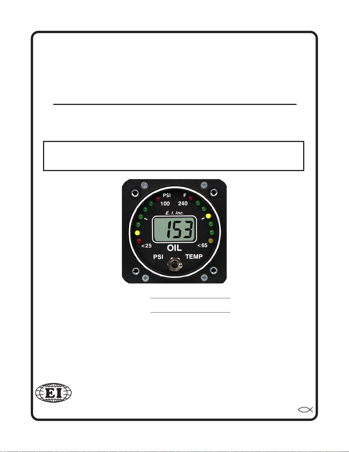
The OPT-1 is a precision oil pressure/temperature instrument featuring dual 90 degree analog displays.
These two displays provide the primary monitoring of oil pressure and temperature and have many advantages over conventional analog gauges as described below.
The digital display provides a method of monitoring oil pressure to 1 PSI or oil temperature to 1’F.
This can be very helpful in detecting trends and allowing you to control your aircraft to divert engine
problems.
The OPT-1 features long term accuracy and reliability. Since the OPT-1 does not incorporate any
moving parts (needles, bearings, springs, etc.) there is little to go wrong or wear out. Also, the internal
microprocessor assures accuracy and repeatability.
The OPT-1 incorporates an external oil pressure transducer mounted in the engine compartment. This
keeps the oil lines out of the cabin, reducing weight and assuring safety.
Analog Display:Analog Display:
Analog Display:
Analog Display:Analog Display:
The dual 90 degree analog displays provide a quick reference for oil temperature and pressure with
respect to their operating ranges. At a glance you can get a relative idea of where in the range you are
operating the engine and how close to the maximum limits you are. Precise information is provided in the
digital display.
An advantage of the analog display is its ability to emit a green, yellow or red light. With a quick
glance you can determine if you’re operating in a normal, caution or restricted range. Also, when you
exceed a maximum limit a red light will blink 20 times at full intensity to catch your attention and warn you
that a maximum limit has been violated. After 20 blinks the red light will stop blinking and display continuous red so it does not distract you.
During night operation the analog lights may be too bright. If so, turn the panel light rheostat up and
the analog lights will dim. The red (maximum limit) light will always be displayed at full intensity.
Digital Display (Oil Pressure):Digital Display (Oil Pressure):
Digital Display (Oil Pressure):
Digital Display (Oil Pressure):Digital Display (Oil Pressure):
By setting the toggle switch on the front of the instrument to "Press" you can monitor oil pressure
changes to 1 PSI. This can be very helpful in detecting problems or in monitoring trends. Abnormally low
oil pressure can be caused by an oil leak, low oil level, worn or defective oil pump, excessively high oil
temperature, contaminated oil or possible other problems. Abnormally high oil pressure can be caused by
a restricted oil line or cold oil temperatures. Oil lubricates and carries heat away from the bearing surfaces
in the engine. Without it, your engine will only run for a few minutes. Become familiar with your normal
operating oil pressure.
3
Rev: A 6/17/92
Page 6

Oil pressure readings at or below 5 PSI will be displayed as "00".
If the digital display backlight has been permanently powered up (as recommended), the digital
display will be easier to see during low ambient light conditions and at night.
Digital Display (Oil TDigital Display (Oil T
Digital Display (Oil T
Digital Display (Oil TDigital Display (Oil T
As the oil passes through the engine, it is heated. It then passes through the oil cooler and reaches a
stable temperature depending on internal engine temperatures, oil flow (pressure, etc.) and oil cooler
efficiency (airspeed, etc.). A change in any of these parameters will cause the oil temperature to increase
or decrease. With the 1’F resolution of the OPT-1, oil temperature changes can be detected easily. This
allows the pilot to diagnose many problems that may never be noticed with a less sensitive gauge.
Maintaining your oil temperatures within operating limits is essential. If the oil exceeds its maximum
operating temperature or if it is operated at excessively high temperatures for a long period of time, the oil
will break down and it will not possess the necessary lubricating properties to protect your engine. The
formula for long engine life is to change your oil at regular intervals and watch your oil temperatures.
Important Information and Initial Check Out:Important Information and Initial Check Out:
Important Information and Initial Check Out:
Important Information and Initial Check Out:Important Information and Initial Check Out:
The installer and aircraft owner must read the Warranty / Agreement before startingThe installer and aircraft owner must read the Warranty / Agreement before starting
1.
The installer and aircraft owner must read the Warranty / Agreement before starting
The installer and aircraft owner must read the Warranty / Agreement before startingThe installer and aircraft owner must read the Warranty / Agreement before starting
the installation.the installation.
the installation. There is information in the Warranty that may alter your decision to install this
the installation.the installation.
instrument.
ment.ment.
ment.
ment.ment.
If you do not accept the terms of the Warranty, do not install this instru-If you do not accept the terms of the Warranty, do not install this instru-
If you do not accept the terms of the Warranty, do not install this instru-
If you do not accept the terms of the Warranty, do not install this instru-If you do not accept the terms of the Warranty, do not install this instru-
emperature):emperature):
emperature):
emperature):emperature):
Installation InstructionsInstallation Instructions
Installation Instructions
Installation InstructionsInstallation Instructions
OPT-1OPT-1
OPT-1
OPT-1OPT-1
2. If you are not an FAA Certified Aircraft Mechanic familiar with the issues of install-2. If you are not an FAA Certified Aircraft Mechanic familiar with the issues of install-
2. If you are not an FAA Certified Aircraft Mechanic familiar with the issues of install-
2. If you are not an FAA Certified Aircraft Mechanic familiar with the issues of install-2. If you are not an FAA Certified Aircraft Mechanic familiar with the issues of installing aircraft Oil Pressure/Temperature instruments, ing aircraft Oil Pressure/Temperature instruments,
ing aircraft Oil Pressure/Temperature instruments,
ing aircraft Oil Pressure/Temperature instruments, ing aircraft Oil Pressure/Temperature instruments,
strument.strument.
strument.
strument.strument.
this instrument (refer to AC 43.13).this instrument (refer to AC 43.13).
this instrument (refer to AC 43.13).
this instrument (refer to AC 43.13).this instrument (refer to AC 43.13).
Check that any necessary FAA Approvals (STC's, etc.) are available for your aircraftCheck that any necessary FAA Approvals (STC's, etc.) are available for your aircraft
3.
Check that any necessary FAA Approvals (STC's, etc.) are available for your aircraft
Check that any necessary FAA Approvals (STC's, etc.) are available for your aircraftCheck that any necessary FAA Approvals (STC's, etc.) are available for your aircraft
before starting the installation. The FAA Approved Model List (AML) is located atbefore starting the installation. The FAA Approved Model List (AML) is located at
before starting the installation. The FAA Approved Model List (AML) is located at
before starting the installation. The FAA Approved Model List (AML) is located atbefore starting the installation. The FAA Approved Model List (AML) is located at
the back of this manual. the back of this manual.
the back of this manual.
the back of this manual. the back of this manual.
lation.lation.
lation.
lation.lation.
4. Before starting installation, read the entire Installation Instructions and resolve any installation,
operating and performance issues you may have. This may eliminate any delays once the installation is started.
5. Check that the instrument make and model marked on the side of the instrument and on the invoice
are correct before starting the installation.
The installer should use current aircraft standards and practices to install The installer should use current aircraft standards and practices to install
The installer should use current aircraft standards and practices to install
The installer should use current aircraft standards and practices to install The installer should use current aircraft standards and practices to install
Resolve any issues you may have before starting the instal-Resolve any issues you may have before starting the instal-
Resolve any issues you may have before starting the instal-
Resolve any issues you may have before starting the instal-Resolve any issues you may have before starting the instal-
4
Do Not attempt to install this in-Do Not attempt to install this in-
Do Not attempt to install this in-
Do Not attempt to install this in-Do Not attempt to install this in-
Rev: C 10/8/97
Page 7

6. Check that the limit information on this instrument matches the published limits in your aircraft's
P.O.H. or Flight Manual. Also, this information may be listed in the T.C. Data Sheet for your
aircraft. Any AD's and/or STC's may set forth additional limitations on the operation of your
engine. The limit information listed in the AML is for unmodified aircraft and is intended for
reference only.
proper instrument calibration and range markings for your aircraft.proper instrument calibration and range markings for your aircraft.
proper instrument calibration and range markings for your aircraft.
proper instrument calibration and range markings for your aircraft.proper instrument calibration and range markings for your aircraft.
On the front of this instrument you will find two red lights marked with the maximum oil pressure
and temperature information. If there are any additional red or yellow lights on this instrument, the
operating range of these lights can be found on a sticker located on the side of the instrument (see
the AML at the back of this manual to decode this information). This instrument designates any
"Caution Range" with yellow LEDs, any "Maximum and Minimum Limits" with Red LEDs and the
"Safe Operating Range" with green LEDs. The "Safe Operating Range" on this instrument is
equivalent to the green "Normal Operating Range" and any unmarked areas on a analog gauge.
Do not attempt to remove or replace the limit information on this instrument. If the oil pressure or
temperature limits for your engine do not match those which are marked on this instrument send
this unit back to Electronics International Inc. for recalibration. DO NOT install or use a primary
engine instrument that is not properly calibrated for your aircraft.
7. Before starting the installation make sure the unit will fit in the location you intend to install it
without obstructing the operation of any controls.
It is the aircraft owner's and/or installer's responsibility to determineIt is the aircraft owner's and/or installer's responsibility to determine
It is the aircraft owner's and/or installer's responsibility to determine
It is the aircraft owner's and/or installer's responsibility to determineIt is the aircraft owner's and/or installer's responsibility to determine
8. If this instrument is to replace an existing unit in the aircraft, it is the installer's responsibility to
move or replace any existing instruments or components in accordance with FAA approved methods and procedures. The following Installation Instructions do not cover moving or the removal of
any existing instruments or components.
Route The Circular Connector:Route The Circular Connector:
Route The Circular Connector:
Route The Circular Connector:Route The Circular Connector:
Starting from under the instrument panel, route the circular connector wire harness up to the instrument mounting location. (See the wiring diagram at the back of this manual). Place the circular connector
about 8 inches back from the panel. Tie wrap the harness in place approximately 1 foot back from the
circular connector. This will allow the harness to be flexible and accommodate varying lengths in instrument wires.
Route the Power and Ground Wires:Route the Power and Ground Wires:
Route the Power and Ground Wires:
Route the Power and Ground Wires:Route the Power and Ground Wires:
In the wire harness is a 6 foot red and black wire used for the pressure transducer and a 3 foot red and
black wire use for instrument power and ground. Route the 3 foot red wire in the harness to the aircraft’s
12 or 24 volt main or emergency bus as applicable via an independent circuit breaker (five amps or less).
An alternate method would be to route the red lead to the bus via a one amp in-line fuse. With this method
a spare fuse should be kept in the aircraft.
Be sure these wires do not obstruct the freedom of travel of any controls.Be sure these wires do not obstruct the freedom of travel of any controls.
Be sure these wires do not obstruct the freedom of travel of any controls.
Be sure these wires do not obstruct the freedom of travel of any controls.Be sure these wires do not obstruct the freedom of travel of any controls.
Route the 3 foot black wire in the harness to a good ground .
not obstruct the freedom of travel of any controls.not obstruct the freedom of travel of any controls.
not obstruct the freedom of travel of any controls.
not obstruct the freedom of travel of any controls.not obstruct the freedom of travel of any controls.
5
Tie wrap these wires so they doTie wrap these wires so they do
Tie wrap these wires so they do
Tie wrap these wires so they doTie wrap these wires so they do
Rev: B 6/3/94
Page 8

Route the Backlight Wires:Route the Backlight Wires:
Route the Backlight Wires:
Route the Backlight Wires:Route the Backlight Wires:
Connect the backlight wires as follows:
1. It is recommended to permanently power up the digital display backlight.
a) For a 12-volt system connect the white/brown wire to the instrument Red Power Lead.
Connect the white/red wire to ground (see Wiring Diagram).
b) For a 24-volt system leave the white/brown open and connect the white/red wire to the
instrument Red Power Lead (see Wiring Diagram).
2. Connect the white/orange wire to the panel light rheostat. This wire will dim the analog LED’s
for night operation when the panel lights are turned on. If this line is left open, the analog LED's
will remain at full intensity at all times. Also, if the voltage on this line drops below 11.5 volts,
the analog LED's will be displayed at full intensity.
struct the freedom of travel of any controls.struct the freedom of travel of any controls.
struct the freedom of travel of any controls. Note: This line may be connected to the CP-1
struct the freedom of travel of any controls.struct the freedom of travel of any controls.
Intensity Control Pot (see price sheet.
Tie wrap all wires so they do not ob-Tie wrap all wires so they do not ob-
Tie wrap all wires so they do not ob-
Tie wrap all wires so they do not ob-Tie wrap all wires so they do not ob-
Route the (Optional) External WRoute the (Optional) External W
Route the (Optional) External W
Route the (Optional) External WRoute the (Optional) External W
The white/yellow wire can be connected to an external light (AL-1), buzzer (ATG-1), voice annunciator
(AV-17), a relay, etc. This wire grounds when the red warning light is on. The current in this line must be
limited to 2/10 of an amp maximum. Exceeding this limit will damage the unit. If this feature is not used,
leave this line open.
controls.controls.
controls.
controls.controls.
Install the Oil Pressure TInstall the Oil Pressure T
Install the Oil Pressure T
Install the Oil Pressure TInstall the Oil Pressure T
Find a convenient location on the fire wall and mount the pressure transducer with the clamp provided.
The oil pressure line does not have to be routed into the cabin area although you will need access on the
cabin side of the fire wall to tighten the pressure transducer clamp nut.
Tie wrap this wire so it does not obstruct the freedom of travel of anyTie wrap this wire so it does not obstruct the freedom of travel of any
Tie wrap this wire so it does not obstruct the freedom of travel of any
Tie wrap this wire so it does not obstruct the freedom of travel of anyTie wrap this wire so it does not obstruct the freedom of travel of any
ransducer:ransducer:
ransducer:
ransducer:ransducer:
PT-100GA Pressure Transducer.
Clamp.
Mounting Screw.
arning Control Line:arning Control Line:
arning Control Line:
arning Control Line:arning Control Line:
Do not mount the pressureDo not mount the pressure
Do not mount the pressure
Do not mount the pressureDo not mount the pressure
Your Adapter (1/8" Female NPT).
FlexibleFlexible
Flexible Aircraft Oil Pressure Line.
FlexibleFlexible
6
Rev: C 10/8/97 *
Page 9

transducer to an engine baffle or directly on the engine supported by an adapter or fitting.transducer to an engine baffle or directly on the engine supported by an adapter or fitting.
transducer to an engine baffle or directly on the engine supported by an adapter or fitting.
transducer to an engine baffle or directly on the engine supported by an adapter or fitting.transducer to an engine baffle or directly on the engine supported by an adapter or fitting.
Vibration can cause the adapter to break, resulting in loss of engine oil. The pressure transducer is
equipped with a 1/8" NPT male port. This port can be adapted any oil pressure line. Use only a flexible
hose and fittings suitable for aircraft use. Route a flexible oil pressure line from the
pick up point to the pressure transducer and tighten all fittings.
sure transducer to tighten the pressure fittings.sure transducer to tighten the pressure fittings.
sure transducer to tighten the pressure fittings.
sure transducer to tighten the pressure fittings.sure transducer to tighten the pressure fittings.
Do not use the case of the oil pres-Do not use the case of the oil pres-
Do not use the case of the oil pres-
Do not use the case of the oil pres-Do not use the case of the oil pres-
primary oil pressure
Some Fittings you may want to consider using are shown below:
1/8 NPT Male
PT-100GA
Install the Oil TInstall the Oil T
Install the Oil T
Install the Oil TInstall the Oil T
Replace your existing primary oil temperature probe with the probe provided in the kit. Oil temperature can vary throughout an engine. Your engine’s oil temperature specifications are based on a specific
location of the oil temperature probe. If this instrument is to be used as a primary instrument, the oil
temperature probe must be installed at the primary oil temperature pick up point. Otherwise the OPT-1
must be placard as a secondary instrument.
If the oil temperature probe must be removed on a regular basis to drain the oil, order a precision
connector for the probe and extension cable to allow for easy disconnect.
emperature Probe:emperature Probe:
emperature Probe:
emperature Probe:emperature Probe:
1/8 NPT
Coupler
AN910-1D
1/8 NPT Male
Flare
#2 Stright - AN816-2D
#3 Stright - AN816-3D
#4 Stright - AN816-4D
#2 45' - MS20823-2D
#3 45' - MS20823-3D
#4 45' - MS20823-4D
#2 90' - MS20822-2D
#3 90' - MS20822-3D
#4 90' - MS20822-4D
Route the Oil TRoute the Oil T
Route the Oil T
Route the Oil TRoute the Oil T
Route the pair of wires with the metal overbraid in the wire harness to the oil temperature probe.
When tie wrapping this cable down, be sure there is no strain or pull against the probe. Keep the probe and
cable leads away from any hot areas such as exhaust stacks or cylinder heads.
Note:Note:
A dab or grease or two drops of oil on the connector will protect it for many years. A dab or grease or two drops of oil on the connector will protect it for many years.
Note:
A dab or grease or two drops of oil on the connector will protect it for many years.
Note:Note:
A dab or grease or two drops of oil on the connector will protect it for many years. A dab or grease or two drops of oil on the connector will protect it for many years.
Be sure the connectors mate properly. If the tab in the male connector gets bent, it can wedge itself
between the red nylon and metal female receptacle. This can result in an intermittent connection after
about a month or more. If the connectors are removed several times the female connector can become
loose. If this happens use a pair of needle nose pliers and tighten the metal receptacle inside the female
connector.
emperature Extension Cable:emperature Extension Cable:
emperature Extension Cable:
emperature Extension Cable:emperature Extension Cable:
7
Rev: B 6/3/94 *
Page 10

Any excess cable can be rolled up and tie wrapped under the instrument panel.
wires so they do not obstruct the freedom of travel of any controls. wires so they do not obstruct the freedom of travel of any controls.
wires so they do not obstruct the freedom of travel of any controls. Do not kink this cable.
wires so they do not obstruct the freedom of travel of any controls. wires so they do not obstruct the freedom of travel of any controls.
Any bend in this cable should have a 1/2 inch or more radius. You may decide to cut the extension cable
to a specific length. If you do this, strip each wire and double the wires over. An extra set of connectors
are provided in the kit. Place a male connector on the red wire and a female connector on the yellow wire.
Double crimp these connectors.
Double the wires over. A good crimp is critical.Double the wires over. A good crimp is critical.
Double the wires over. A good crimp is critical.
Double the wires over. A good crimp is critical.Double the wires over. A good crimp is critical.
Tie wrap theseTie wrap these
Tie wrap these
Tie wrap theseTie wrap these
Route the Pressure TRoute the Pressure T
Route the Pressure T
Route the Pressure TRoute the Pressure T
In the wire harness is a 3 foot red and black wire used for instrument power and ground and a 6 foot
red and black wire used for the pressure transducer. Route the four 6 foot pressure transducer wires (red,
black, green and white) in the wire harness to the pressure transducer and cut to length. These wires
maybe spliced if extra wire length is required. Install the male connectors supplied with the kit on the four
wires and connect them to the pressure transducer matching the colors of the wires. Be sure the wires are
doubled over and double crimped onto the connectors.
the freedom of travel of any controls.the freedom of travel of any controls.
the freedom of travel of any controls.
the freedom of travel of any controls.the freedom of travel of any controls.
Note:Note:
A dab or grease or two drops of oil on the connector will protect it for many years. A dab or grease or two drops of oil on the connector will protect it for many years.
Note:
A dab or grease or two drops of oil on the connector will protect it for many years.
Note:Note:
A dab or grease or two drops of oil on the connector will protect it for many years. A dab or grease or two drops of oil on the connector will protect it for many years.
Keep the tab straight.
Install the Instrument in the PInstall the Instrument in the P
Install the Instrument in the P
Install the Instrument in the PInstall the Instrument in the P
ransducer Extension Wires:ransducer Extension Wires:
ransducer Extension Wires:
ransducer Extension Wires:ransducer Extension Wires:
Tie wrap these wires so they do not obstructTie wrap these wires so they do not obstruct
Tie wrap these wires so they do not obstruct
Tie wrap these wires so they do not obstructTie wrap these wires so they do not obstruct
Double the
wires.
Double Crimp.
anel:anel:
anel:
anel:anel:
Install the instrument from behind the instrument panel using 6 x 32 screws. These screws should not
be any longer than 1/2". Tie wrap any loose wires as needed.
Connect the Circular Connector to the Instrument:Connect the Circular Connector to the Instrument:
Connect the Circular Connector to the Instrument:
Connect the Circular Connector to the Instrument:Connect the Circular Connector to the Instrument:
1) Push the two mating connectors together and twist them until they snap into position.
2) Turn the locking ring on the instrument connector clockwise (1 1/2 turns) until it locks into posi-
tion.
Check Instrument Operation:Check Instrument Operation:
Check Instrument Operation:
Check Instrument Operation:Check Instrument Operation:
Check instrument operation as follows:
1. Turn the master switch on (engine off) and verify that the instrument sequences through all the
analog lights. A problem at this step could be caused by poor connections on the red and/or black
leads.
8
Rev: A 6/17/92
Page 11

2. Set the instrument toggle switch to "Oil Press" and check for a digital oil pressure reading of "00."
A problem at this step could be caused by a poor connection or crossed pressure transducer wires.
The voltage on the pressure transducer wires (with the transducer connected to the unit) should mea-
sure as follows:
Red Wire - +5 Volts.
Black Wire - 0 Volts.
Green Wire - 1.65 Volts.
White Wire - 1.65 Volts.
3. Set the instrument toggle switch to "Temp" and check the instrument to read proper oil temperature.
A problem at this step could be caused by poor or improper connections between the oil temp probe
and instrument. If the instrument is not connected to the oil temperature probe it will read cabin
temperature. By applying a small amount of heat to the oil temperature probe the oil temperature
readings will increase one degree at a time.
4. Check the digital display backlight. With high or medium ambient light it is hard to see the digital
display backlight (it is only required during low ambient light conditions but should be on all the
time).
5. If the analog LED dimming wire has been connected, turn the panel light rheostat up and look for
the analog lights to dim.
Note: If any red warning light is on, none of the analog lights will dim.
6. Start the aircraft engine and check the digital and analog displays to read oil pressure properly. A
problem at this step could be caused by a poor connection or crossed pressure transducer wires.
Measure the voltage on the pressure transducer wires as listed in step 2. If the voltage measurements
are correct and the oil pressure reads "00", the white and green wires between the pressure transducer
and instrument may be reversed.
7. With the engine running, check the digital and analog displays to read oil temperature properly. If
there is a problem at this point see step 3 above for troubleshooting information.
After running the engine, check the engine and pressure transducer fittings for oilAfter running the engine, check the engine and pressure transducer fittings for oil
8.
After running the engine, check the engine and pressure transducer fittings for oil
After running the engine, check the engine and pressure transducer fittings for oilAfter running the engine, check the engine and pressure transducer fittings for oil
leaks.leaks.
leaks.
leaks.leaks.
9
Rev: A 6/17/92
Page 12

Do not use screwsDo not use screws
Do not use screws
Do not use screwsDo not use screws
longer than 1/2" (4 ea.).longer than 1/2" (4 ea.).
longer than 1/2" (4 ea.).
longer than 1/2" (4 ea.).longer than 1/2" (4 ea.).
Circular Connector
Oil Pressure/TOil Pressure/T
Oil Pressure/T
Oil Pressure/TOil Pressure/T
Wiring Diagram Wiring Diagram
Wiring Diagram
Wiring Diagram Wiring Diagram
WD 0315911
emp (OPTemp (OPT
emp (OPT
emp (OPTemp (OPT
-1)-1)
-1)
-1)-1)
Red
Black
White/
Brwn
White/Red
White/
Orng
White/Yel
Wire Harness
Red
Yellow
6' Red Wire
6' Black Wire
6' White Wire
6' Green Wire
3' Power Lead, connects to 12 or 24 Volt Bus.
3' Ground Lead, connects to Ground.
3' 12V Backlight Control Line, connects to Red Power Lead for a 12V
system. 12 volts turns on the digital display backlight.
3' 24V Backlight Control Line, connects to Red Power Lead for a 24V
system.
Connect to ground for 12 Volt System.Connect to ground for 12 Volt System.
Connect to ground for 12 Volt System.
Connect to ground for 12 Volt System.Connect to ground for 12 Volt System.
3' Analog LED Lighting Control Line, connects to Panel Light Rheostat.
12/24 volts dims the analog LEDs.
3' (Optional) External Warning Control Line. Can be connected to a relay
to control an external light, buzzer, etc. Grounds when Red Warning
Light is on. Current must be limited to 2/10 amp maximum.
6' Extension Cable with Overbraid
Connect the same color of 6' wires from
Oil Temp Probe.
the unit to the pressure transducer.
Connectors are supplied in the kit. Be
sure these wires are connected properly.
Red
Black
White
Green
Pressure
Transducer
PT-100GA
10
Install Connectors. Double wires
and crimp tight when installing
connectors.
Rev: A 6/17/92
Page 13

OPT-1 Circular ConnectorOPT-1 Circular Connector
OPT-1 Circular Connector
OPT-1 Circular ConnectorOPT-1 Circular Connector
Connecting Cable Harness, Back View (wire side)
OR
Instrument Connector, Front View
14
2
Blk
Red
1
Note: See Wiring Diagram for
hook up information.
W/
6
Org
10
W/
Red
WhtGrn
W/
Brn
Blk
W/
Yel
Red
11
3
7
11 to 14 (Oil Pressure Transducer Wires).
Yel
Red
1516
Oil Temp. Extension Cable
with overbraid.
11
Rev: A 6/17/92
Page 14

Specifications and Operating FeaturesSpecifications and Operating Features
Specifications and Operating Features
Specifications and Operating FeaturesSpecifications and Operating Features
Model:
OPT-1 (Oil Pressure/Temperature Instrument)
Case Dimensions:
2.5" x 2.5" x 3.65" depth, 2 1/4" Bezel.
Weight:
Unit Only: 10 Oz.
Pressure Transducer: 8 Oz.
Temp Probe and 6 ft. cable: 4 Oz.
Extra Extension cable: .33 Oz./ft.
Environmental:
Meets TSO C47/C43a.
Power Requirements:
7.5 to 35 Volts, 1/10 Amp.
Analog Display:
Two sets of 7 High Intensity Light Emitting Diodes (LEDs) in a 90 degree arc with Intensity Control
Line available for dimming. Sequential flash test on power up. Microprocessor eliminates LED
hunting (flicker).
PT-100GA Pressure Transducer:
0 to 100 PSI
300 PSI Proof
500 PSI Burst
1/8" NPT female
P-120 Temperature Probe:
-50'F to 700'F
5/8 - 18 Thread
Red LEDs:
If the Analog Display goes from a Green LED or Yellow LED to a Red LED, the Red LED will blink
20 times then go solid Red. Red Limit LEDs are always displayed at full intensity.
Digital Display:
LCD (viewable in direct sunlight), with 12 and 24 volt backlight control wires for night operation.
Displays "8888" on power up.
Accuracy:
Pressure: 2% in accordance with TSO C47/C43a.
Temperature: 2% in accordance with TSO C47/C43a.
Resolution:
Pressure: 1 PSI. (Readings at or below 5 PSI will be displayed as "00")
Temperature:1’F.
Max Displayed Range (Unit Only):
Pressure: 5 to 999 PSI.
Temperature: 0 to 1999’F.
Update Time:
2 times per second.
External Warning Control Line:
Grounds when any Red Warning Light is on or blinking. Current should be limited to 2/10 amp.
12
Rev: C 10/8/97 *
 Loading...