

Page 1
Primary Glass Panel Engine MonitorPrimary Glass Panel Engine Monitor
Primary Glass Panel Engine Monitor
Primary Glass Panel Engine MonitorPrimary Glass Panel Engine Monitor
CGR-30PCGR-30P
CGR-30P
CGR-30PCGR-30P
Installation InstructionsInstallation Instructions
Installation Instructions
Installation InstructionsInstallation Instructions
II 02151301
You must read this manual before installing or operating the instrument. This
manual contains warranty and other information that may affect your decision
to install this product and/or the safety of your aircraft.
The CGR-30P is a FAA Approved Primary Replacement
for Engine and Aircraft System Instruments
Rev. B: 6/21/13
Model #:Model #:
Model #:
Model #:Model #:
S/N:S/N:
S/N:
S/N:S/N:
Electronics International Inc. Electronics International Inc.
Electronics International Inc.
Electronics International Inc. Electronics International Inc.
63296 Powell Butte Hwy • Bend, OR 97701 • (541) 318-6060 • Buy-EI.com 63296 Powell Butte Hwy • Bend, OR 97701 • (541) 318-6060 • Buy-EI.com
63296 Powell Butte Hwy • Bend, OR 97701 • (541) 318-6060 • Buy-EI.com
63296 Powell Butte Hwy • Bend, OR 97701 • (541) 318-6060 • Buy-EI.com 63296 Powell Butte Hwy • Bend, OR 97701 • (541) 318-6060 • Buy-EI.com
®®
®
®®
Page 2
Important Notice
***** MUST READ *****
Page 1 of 4
If you think it is not important to read this manual, you're wrong!If you think it is not important to read this manual, you're wrong!
If you think it is not important to read this manual, you're wrong! This manual contains impor-
If you think it is not important to read this manual, you're wrong!If you think it is not important to read this manual, you're wrong!
tant operating information that may affect the safety of the pilot, passengers, aircraft, operation of the
system or time to install the system. You MUST read the manual prior to installing this system. Any
deviation from these installation instructions is the sole responsibility of the installer and should be done
in accordance with AC 43.13.
Read the Warranty/AgreementRead the Warranty/Agreement
Read the Warranty/Agreement. There is information in the Warranty/Agreement that may alter your
Read the Warranty/AgreementRead the Warranty/Agreement
decision to install this product.
not install this productnot install this product
not install this product. This product may be returned for a refund. Contact Electronics International
not install this productnot install this product
Inc. for details.
If you are not an FAA Certified Aircraft Mechanic familiar with the issues of installingIf you are not an FAA Certified Aircraft Mechanic familiar with the issues of installing
If you are not an FAA Certified Aircraft Mechanic familiar with the issues of installing
If you are not an FAA Certified Aircraft Mechanic familiar with the issues of installingIf you are not an FAA Certified Aircraft Mechanic familiar with the issues of installing
aircraft EGT, CHT, RPM, M.P, Fuel Level, Fuel Flow, Fuel Pressure, Volt, Amp, Oil Tem-aircraft EGT, CHT, RPM, M.P, Fuel Level, Fuel Flow, Fuel Pressure, Volt, Amp, Oil Tem-
aircraft EGT, CHT, RPM, M.P, Fuel Level, Fuel Flow, Fuel Pressure, Volt, Amp, Oil Tem-
aircraft EGT, CHT, RPM, M.P, Fuel Level, Fuel Flow, Fuel Pressure, Volt, Amp, Oil Tem-aircraft EGT, CHT, RPM, M.P, Fuel Level, Fuel Flow, Fuel Pressure, Volt, Amp, Oil Temperature and Pressure instruments, perature and Pressure instruments,
perature and Pressure instruments,
perature and Pressure instruments, perature and Pressure instruments,
should use current aircraft standards and practices to install this system (refer to ACshould use current aircraft standards and practices to install this system (refer to AC
should use current aircraft standards and practices to install this system (refer to AC
should use current aircraft standards and practices to install this system (refer to ACshould use current aircraft standards and practices to install this system (refer to AC
43.13).43.13).
43.13).
43.13).43.13).
If you do not accept the terms of the Warranty/Agreement, doIf you do not accept the terms of the Warranty/Agreement, do
If you do not accept the terms of the Warranty/Agreement, do
If you do not accept the terms of the Warranty/Agreement, doIf you do not accept the terms of the Warranty/Agreement, do
Do Not attempt to install this instrument.Do Not attempt to install this instrument.
Do Not attempt to install this instrument.
Do Not attempt to install this instrument.Do Not attempt to install this instrument.
The installer The installer
The installer
The installer The installer
If the installer does not have the skills, knowledge, tools, equipment or facility, to perform and determine
whether the installation of this product is safe, reliable and accurate and to determine whether this product
is operating properly after installation,
or installer are unwilling to take the responsibility for the installation and operation of this product,
NOT INSTALL THIS PRODUCT.NOT INSTALL THIS PRODUCT.
NOT INSTALL THIS PRODUCT. This product may be returned for a refund. Contact Electronics
NOT INSTALL THIS PRODUCT.NOT INSTALL THIS PRODUCT.
International Inc. for details.
By installing this product, the aircraft owner/pilot and installer agree to hold Electronics International Inc.
harmless and in no way responsible for monetary compensation, including punitive damages for any
incident, harm and/or damage associated with this product. If you do not agree to the above,
INSTALL THIS PRODUCT.INSTALL THIS PRODUCT.
INSTALL THIS PRODUCT. This product may be returned for a refund. Contact Electronics Interna-
INSTALL THIS PRODUCT.INSTALL THIS PRODUCT.
tional Inc. for details.
Electronics International Inc. is not liable or responsible for a pilot’s action or any situation that results in
personal injury, property damage, missed commitments, lack of use of an aircraft or any expenses incurred due to: product failure, inaccuracy in displayed data or text files, display or display format issues,
software bugs or problems, upgrade or customization issues, misinterpretation of the display, warning
and/or limit settings, calibration problems, installation issues (leaks, mis-wiring, obstructions, damage to
aircraft or components, incorrect installation of any parts, wrong parts, parts that don’t fit, etc.) or any
other issues related to the installation or operation of this product. All of the above are solely the pilot’s
and/or installer’s responsibility. The pilot
aircraft. The pilot must not allow anyone to operate the aircraft that does not know the operation of this
product. The pilot must keep the instrument Operating Instructions in the aircraft at all times. If you do
not agree to the above,
refund. Contact Electronics International Inc. for details.
DO NOT INSTALL THIS PRODUCT.DO NOT INSTALL THIS PRODUCT.
DO NOT INSTALL THIS PRODUCT. This product may be returned for a
DO NOT INSTALL THIS PRODUCT.DO NOT INSTALL THIS PRODUCT.
DO NOT INSTALL THIS PRODUCTDO NOT INSTALL THIS PRODUCT
DO NOT INSTALL THIS PRODUCT. If the owner/pilot and/
DO NOT INSTALL THIS PRODUCTDO NOT INSTALL THIS PRODUCT
DODO
DO
DODO
DO NOTDO NOT
DO NOT
DO NOTDO NOT
mustmust
must understand the operation of this product before flying the
mustmust
Page 3

Important Notice
***** MUST READ *****
Page 2 of 4
Do not install a non-certified CGR-30P (CGR) in a certified aircraft. A certified CGR lists the applicable TSO numbers at the bottom of the Model Label.
Before starting the installation make sure the unit will fit in the location you intend to install it without
obstructing the operation of any controls.
If the CGR is configured to monitor the aircrafts fuel tanks, the CGR must be calibrated to the aircraft
fuel system and the CGR's accuracy must be verified before flying the aircraft.
The accuracy and proper operation of each function displayed on the CGR should be verified before
the aircraft is released for flight.
When the installation is finished, inspect the system for loose fittings, connections, clamps, probes and
inspect for leaks, chafing, obstructions, heat damage and anything that may cause unsafe flight before
the 1st run-up, after the 1st run-up and after the first flight.
Before allowing the aircraft to be flown, verify the instrument markings displayed on the CGR screens
are accurate with the aircraft’s POH for every function displayed on the CGR.
Before allowing anyone to operate the aircraft they must read the Operating Manual including the
Important Notice there in. Keep the Operating Instructions in the aircraft at all times.
The use of the
is installed. Recurring training should include reading the
Manual and seeking a flight instructor for proper interpretation of information being displayed to the
pilot.
CGR requires recurring training for any pilot who will be flying the aircraft in which it
CGR Installation Manual and Operations
Page 4

Important Notice
***** MUST READ *****
Page 3 of 4
Fuel Level Accuracy Limitations:
It is the pilot/owner’s obligation to makeIt is the pilot/owner’s obligation to make
The accuracy limitations of the CGR are listed below.
anyone flying the aircraft aware of these limitations.anyone flying the aircraft aware of these limitations.
anyone flying the aircraft aware of these limitations.
anyone flying the aircraft aware of these limitations.anyone flying the aircraft aware of these limitations.
1. Angle of Attack -1. Angle of Attack -
1. Angle of Attack - The CGR must be calibrated with the aircraft in a cruise angle of attack. If
1. Angle of Attack -1. Angle of Attack the aircraft is in an angle of attack other than cruise, the CGR may display inaccurate fuel levels
(depending on the mounting location and type of sensor used). If your aircraft does not sit at a cruise
angle of attack when on the ground, it may not display accurate fuel levels.
different angles of attack to see the affects on the CGR fuel level readings.different angles of attack to see the affects on the CGR fuel level readings.
different angles of attack to see the affects on the CGR fuel level readings.
different angles of attack to see the affects on the CGR fuel level readings.different angles of attack to see the affects on the CGR fuel level readings.
Full Fuel Readings -Full Fuel Readings -
2.
Full Fuel Readings - As a tank is filled the fuel sensor may not be able to detect the fuel enter-
Full Fuel Readings -Full Fuel Readings ing the upper corners of the fuel tank. If this is the case with your sensor, the CGR will display lower
fuel levels than the actual fuel in the tanks when the tanks are full. When the fuel level drops to a
point where the fuel sensor starts to detect a change, the displayed fuel level should be accurate.
Check the accuracy of your system by comparing the displayed fuel levels on the CGRCheck the accuracy of your system by comparing the displayed fuel levels on the CGR
Check the accuracy of your system by comparing the displayed fuel levels on the CGR
Check the accuracy of your system by comparing the displayed fuel levels on the CGRCheck the accuracy of your system by comparing the displayed fuel levels on the CGR
to the fuel levels listed in the flight manual at each fill up.to the fuel levels listed in the flight manual at each fill up.
to the fuel levels listed in the flight manual at each fill up.
to the fuel levels listed in the flight manual at each fill up.to the fuel levels listed in the flight manual at each fill up.
It is the pilot/owner’s obligation to make
It is the pilot/owner’s obligation to makeIt is the pilot/owner’s obligation to make
Test your aircraft atTest your aircraft at
Test your aircraft at
Test your aircraft atTest your aircraft at
3. Low Fuel Readings - 3. Low Fuel Readings -
3. Low Fuel Readings -
3. Low Fuel Readings - 3. Low Fuel Readings -
for an indicated tank level below 1/8for an indicated tank level below 1/8
for an indicated tank level below 1/8
for an indicated tank level below 1/8for an indicated tank level below 1/8
maintain at least the FAA minimum fuel requirements in the aircraft at all times.
4. Improper Calibration -4. Improper Calibration -
4. Improper Calibration - If the CGR has not been properly calibrated it will not display accurate
4. Improper Calibration -4. Improper Calibration fuel levels in the tanks. It is important you verify the accuracy of the CGR.
your measured fuel levels in the tanks with the readings on the CGR before each flight.your measured fuel levels in the tanks with the readings on the CGR before each flight.
your measured fuel levels in the tanks with the readings on the CGR before each flight.
your measured fuel levels in the tanks with the readings on the CGR before each flight.your measured fuel levels in the tanks with the readings on the CGR before each flight.
5. Poor Connections -5. Poor Connections -
5. Poor Connections - Poor connections between the wires leading from the EDC to the fuel
5. Poor Connections -5. Poor Connections sensors can become intermittent. An intermittent connection most likely will show up as wandering or
inaccurate readings on the CGR.
with the readings on the CGR before each flight.with the readings on the CGR before each flight.
with the readings on the CGR before each flight.
with the readings on the CGR before each flight.with the readings on the CGR before each flight.
6. Defective Fuel Level Sensors -6. Defective Fuel Level Sensors -
6. Defective Fuel Level Sensors - Fuel sensors can become intermittent or change resistance
6. Defective Fuel Level Sensors -6. Defective Fuel Level Sensors with age. It is not uncommon to find intermittent problems even in new sensors. An intermittent
problem with a fuel sensor most likely will show up as wandering or inaccurate readings on the CGR.
Always crosscheck the measured fuel levels in the tanks with the readings on the CGR atAlways crosscheck the measured fuel levels in the tanks with the readings on the CGR at
Always crosscheck the measured fuel levels in the tanks with the readings on the CGR at
Always crosscheck the measured fuel levels in the tanks with the readings on the CGR atAlways crosscheck the measured fuel levels in the tanks with the readings on the CGR at
each fill up.each fill up.
each fill up.
each fill up.each fill up.
If you ever find an inaccuracy issue or any other problem with a fuel level display onIf you ever find an inaccuracy issue or any other problem with a fuel level display on
If you ever find an inaccuracy issue or any other problem with a fuel level display on
If you ever find an inaccuracy issue or any other problem with a fuel level display onIf you ever find an inaccuracy issue or any other problem with a fuel level display on
the CGR, troubleshoot and fix the problem before flying the aircraft.the CGR, troubleshoot and fix the problem before flying the aircraft.
the CGR, troubleshoot and fix the problem before flying the aircraft.
the CGR, troubleshoot and fix the problem before flying the aircraft.the CGR, troubleshoot and fix the problem before flying the aircraft.
Do not rely on the CGR to determine the fuel level in the tankDo not rely on the CGR to determine the fuel level in the tank
Do not rely on the CGR to determine the fuel level in the tank
Do not rely on the CGR to determine the fuel level in the tankDo not rely on the CGR to determine the fuel level in the tank
. .
. You should always fly the aircraft in such a manner as to
. .
Always crosscheckAlways crosscheck
Always crosscheck
Always crosscheckAlways crosscheck
Always crosscheck your measured fuel levels in the tanksAlways crosscheck your measured fuel levels in the tanks
Always crosscheck your measured fuel levels in the tanks
Always crosscheck your measured fuel levels in the tanksAlways crosscheck your measured fuel levels in the tanks
If you do not agree to all of the above,
be returned for a refund. Contact Electronics International Inc. for details.
DO NOT INSTALL THIS PRODUCT.DO NOT INSTALL THIS PRODUCT.
DO NOT INSTALL THIS PRODUCT. This product may
DO NOT INSTALL THIS PRODUCT.DO NOT INSTALL THIS PRODUCT.
Page 5

Important Notice
***** MUST READ *****
Page 4 of 4
Important Fuel Level Considerations:
DO NOT RELY SOLELY ON THE FUEL LEVEL DISPLAYED ON THE CGR TO
DETERMINE THE FUEL LEVELS IN THE AIRCRAFT. The use of the CGR does not
eliminate or reduce the necessity for the pilot to use good flight planning, preflight and in-flight
techniques for managing fuel. It is important the pilot adopt the practices listed below. If you are
not familiar with these techniques, contact the FAA to acquire proper training.
1. A copy of the Operating Manual must be in the aircraft at all times.
2. Flight Planning - Always calculate the fuel requirement for each leg of a flight, including any
alternate plans for bad weather. Keep this information available in the aircraft during the
flight. Keep a chart of the published fuel flows for various flight/engine conditions in the
aircraft. Keep a chart of the measured fuel flows for various flights in the aircraft. Measured
fuel flows can be considerably different from published figures. This usually is due to old,
inaccurate engine instruments.
3. Preflight - Do not rely on the CGR to determine the fuel level in the fuel tanks. The
pilot must visually check/measure the fuel levels in the tanks before every takeoff.
Crosscheck the measured fuel levels with the displayed levels on the CGR. Also, crosscheck
these levels with the fuel requirements for the flight listed in your flight plan.
4. In Flight - Make the CGR part of your normal instrument scan. Crosscheck the fuel levels
displayed on the CGR with your flight plan at each leg of the flight or every 30 minutes
(whichever happens first). If there is a discrepancy, land the aircraft at the nearest airport and
verify the fuel levels.
5. New Pilot or Owner of the Aircraft - If there is a new pilot or owner of the aircraft, it is
the previous aircraft pilot/owner’s responsibility to insure the new pilot has read this
manual and is aware of any accuracy limitations and other important considerations.
All limitations and operating characteristics learned from operating the CGR must be
passed on to the new pilot/owner.
If you do not agree or are unwilling to comply with the information/requirements contained within this
Important Notice,
refund. Contact Electronics International Inc. for details.
DO NOT INSTALL THIS PRODUCT.DO NOT INSTALL THIS PRODUCT.
DO NOT INSTALL THIS PRODUCT. This product may be returned for a
DO NOT INSTALL THIS PRODUCT.DO NOT INSTALL THIS PRODUCT.
Discrepancies should be taken seriously.
Page 6

Contents
(Page 1 of 3)
Warranty/Agreement-------------------------------------------------------------------------------------- 1A
1.0 System Overview ------------------------------------------------------------------------------------- 2
1.1 System Description --------------------------------------------------------------------------- 3
1.1.1 CGR Display ---------------------------------------------------------------------------- 3
1.1.2 EDC-33P --------------------------------------------------------------------------------- 3
1.1.3 Probes, Transducers and Modules --------------------------------------------------- 3
1.1.4 Wiring & Extension Cables ----------------------------------------------------------- 3
1.2 Operational Overview ------------------------------------------------------------------------------- 4
1.3 Installation Overview
1.4 Password Protection
1.4.1 User Password ------------------------------------------------------------------------------- 5
1.4.2 Maintenance Password --------------------------------------------------------------------- 5
1.4.3 OEM/Experimental Password ------------------------------------------------------------ 6
2.0 Hardware Installation -------------------------------------------------------------------------------- 7
2.1 Important Information and Initial Check Out: ------------------------------------------- 8
2.2 Review the "EDC Wiring Work Sheets:" ------------------------------------------------- 9
2.3 Verify you have all the necessary Probes, Modules, Transducers and Cables: ----- 9
2.4 Install the CGR Display: --------------------------------------------------------------------- 9
2.5 Install the Temperature Probes: ------------------------------------------------------------- 10
2.6 Install the Pressure Transducers: ----------------------------------------------------------- 12
2.7 Install the Interface Circuit for Annunciators -------------------------------------------- 14
2.8 Install the CO Detector, G-Sensor and/or Other Available CGR Options ------- 15
2.9 Install the Shunt: ------------------------------------------------------------------------------ 15
2.10 Install the Fuel Flow Transducer: -------------------------------------------------------- 17
2.11 Install the P-300C Fuel Level Probes (OEM or Experimental) --------------------- 24
2.12 Install the P-300M Fuel Levl Sender: ---------------------------------------------------- 24
2.13 Install the Resistive Fuel Level Module (RFLM-4-X): ------------------------------- 25
2.14 Install the Voice Alarm Control Panel (OEM or Experimental): ------------------- 25
2.15 Install the Intensity Control Pot (Optional): -------------------------------------------- 25
2.16 Install the Master Warning (red) and Caution (yellow) Lights: ----------------------- 26
2.17 Install the EDC-33P: ------------------------------------------------------------------------ 26
--------------------------------------------------------------------------------- 4
---------------------------------------------------------------------------------- 5
3.0 Install the EDC Wire Harnesses and Route Wires ---------------------------------------------- 27
3.1 Attach the three EDC 37-pin wire harnesses to the EDC: ---------------------------- 28
3.2 Connect the EDC Harness to the Temperature Probes: -------------------------------- 28
3.3 Connect the EDC Harness to the Pressure Transdcueres: ----------------------------- 28
3.4 Connect the EDC Harness to the Shunt: -------------------------------------------------- 29
3.5 Connect the EDC Harness to the Fuel Flow Transducer: ----------------------------- 29
3.6 Connect the EDC Harness to the Existing Capacitive Fuel Level System: -------- 29
3.7 Connect the RFLM-4-x Harness to the EDC Connector and to the Resistive
Fuel Level Sensors: ------------------------------------------------------------------------------- 30
Page 7

Contents
(Page 2 of 3)
3.8 Connect the EDC Harness to the EI P-300C Capacitive Fuel Level Probes: ----- 30
3.9 Connect the EDC Harness to the P-300M Magnetic Fuel Level Senders: ---------- 31
3.10 Connect the EDC Harness (Volts Meassurement Pin) to the Bus: ----------------- 31
3.11 Connect the EDC Harness to the RPM Signals: ---------------------------------------- 31
3.12 Setup the EDC for a 4 or 6-Cylinder Engine: ------------------------------------------- 31
3.13 Connect the EDC Harness to the VI-221's (Voltage Interface Units): ------------- 31
3.14 Connect the EDC Harness to Power and Ground: ------------------------------------ 32
3.15 Route the EDC 5V-Serial Wire to the CGR Connector: ------------------------------ 32
4.0 Install the CGR Wire Harness and Route the Wires ------------------------------------------- 33
4.1 Attach the CGR 25-pin D-sub Connector to the CGR: -------------------------------- 34
4.2 Connect the EDC 5V-Serial Output Wire to the CGR 5V-Serial Input Wire: ----- 34
4.3 Connect the CGR Harness to the Master Warning and Caution Lights: ------------- 34
4.4 Connect the CGR Harness to the Voice Alarm Control Panel (AV-17CP): -------- 34
4.5 Connect the CGR Harness to the Audio Panel (OEM/Experimental): ------------- 35
4.6 Connect the CGR Harness to the Backlight Control Pot: ------------------------------ 35
4.7 Connect the CGR Harness to the Moving Map Data Out from the GPS: ---------- 35
4.8 Connect the CGR Harness to the Fuel Data Input on the GPS: ---------------------- 35
4.9 Connect the CGR Harness to Power and Ground: -------------------------------------- 36
4.10 Connect the CGR Harness to the CO-Guardian CO Detector: --------------------- 36
5.0 Mandatory System Setup and Checkout --------------------------------------------------------- 37
5.1 Power-On Checkout -------------------------------------------------------------------------- 38
5.2 Perform all Steps Listed in the "CGR-30P Setup Checklist" ------------------------ 38
5.3 Ground Run Checkout ------------------------------------------------------------------------ 38
5.4 First Flight Checkout -------------------------------------------------------------------------- 39
5.5 Read the "Warranty/Agreement" and the "Important Notice" ----------------------- 39
6.0 Installation Data -------------------------------------------------------------------------------------- 40
6.1 Instructions for Continued Airworthiness (ICA): ----------------------------------------- 41
6.2 Airworthiness Limitations: -------------------------------------------------------------------- 41
6.3 Installing a D-sub Pin onto a TC or Tin Copper Wire: ---------------------------------- 41
CGR-30P Wiring Work Sheet -------------------------------------------------------------------- 43
EDC Wiring Work Sheet Top Connector ------------------------------------------------------ 44
EDC Wiring Work Sheet Middle Connector --------------------------------------------------- 45
EDC Wiring Work Sheet Bottom Connector -------------------------------------------------- 46
EDC Template -------------------------------------------------------------------------------------- 47
7.0 Troubleshooting --------------------------------------------------------------------------------------- 48
7.1 CGR or EDC Problem ------------------------------------------------------------------------ 49
7.2 Pressure Problem with one Function ------------------------------------------------------- 50
7.3 Temperature Problem on all Channels ----------------------------------------------------- 50
7.4 Temperature Problem with one Function ------------------------------------------------- 51
7.5 RPM Problem ----------------------------------------------------------------------------------- 51
7.6 Fuel Flow Problem ----------------------------------------------------------------------------- 52
Page 8

Contents
(Page 3 of 3)
7.7 Amp Problem ----------------------------------------------------------------------------------- 53
7.8 Resistive Fuel Level Problem ---------------------------------------------------------------- 53
7.9 Capacitive Fuel Level Problem -------------------------------------------------------------- 54
7.10 Voltage Problem ------------------------------------------------------------------------------ 55
7.11 Annunciator Problem ------------------------------------------------------------------------ 55
8.0 Technical Data ---------------------------------------------------------------------------------------- 56
Specifications, Functions and Features ---------------------------------------------------------- 57
Appendix ---------------------------------------------------------------------------------------------------- A
A1.0 Appendix: LASAR Ignition RPM Filter -------------------------------------------------- A1.0
A2.0 Appendix EDC-33P-8 for 7, 8, 9-Cylinder Engines and High RPM Engines ---- A2.0
A3.0 Appendix Connecting an EDC RPM Channel to a Lightspeed Plasma II or
III Ignition --------------------------------------------------------------------------------------- A3.0
Page 9

Warranty / Agreement
Electronics International Inc. (EI) warrants this instrument and system components to be free from defects in
materials and workmanship for a period of one year from the user invoice date. EI will repair or replace any
item under the terms of this Warranty provided the item is returned to the factory prepaid.
If you do not agree to and accept If you do not agree to and accept
1.
If you do not agree to and accept
If you do not agree to and accept If you do not agree to and accept
This ProductThis Product
This Product
This ProductThis Product
2. Electronics International Inc. is not liable or responsible for a pilot’s action or any situation that results in
personal injury, property damage, missed commitments, lack of use of an aircraft or any expenses incurred due
to: product failure, inaccuracy in displayed data or text files, display or display format issues, software bugs or
problems, upgrade or customization issues, misinterpretation of the display, warning and/or limit settings,
calibration problems, installation issues (leaks, mis-wiring, obstructions, damage to aircraft or components,
incorrect installation of any parts, wrong parts, part that don’t fit, etc.) or any other issues related to the installation or operation of this product. All of the above are solely the pilot’s and/or installer’s responsibility. The
mustmust
pilot
must
mustmust
to operate the aircraft that does not know the operation of this product. The pilot will keep the instrument's
Operating Instructions in the aircraft at all times.
By installing this product, the aircraft owner/pilot and installer agree to hold Electronics International Inc.
harmless and in no way responsible for monetary compensation, including punitive damages for any incident,
harm and/or damage associated with this product (including but not limited to the ones listed above). If you do
not agree to any part of this Warranty/Agreement,
3. This Warranty/Agreement shall not apply to any product that has been repaired or altered by any person
other than Electronics International Inc., or that has been subjected to misuse, accident, incorrect wiring,
negligence, improper or unprofessional assembly or improper installation by any person.
does not cover any reimbursement for any person’s time for installation, removal, assembly ordoes not cover any reimbursement for any person’s time for installation, removal, assembly or
does not cover any reimbursement for any person’s time for installation, removal, assembly or
does not cover any reimbursement for any person’s time for installation, removal, assembly ordoes not cover any reimbursement for any person’s time for installation, removal, assembly or
repair.repair.
repair. Electronics International retains the right to solely determine the reason or cause for warranty repair.
repair.repair.
. .
. You may return the product for a refund, contact Electronics International Inc. for details.
. .
understand the operation of this product before flying the aircraft. The pilot will not allow anyone
ALLALL
the terms of this Warranty/Agreement, the terms of this Warranty/Agreement,
ALL
the terms of this Warranty/Agreement,
ALLALL
the terms of this Warranty/Agreement, the terms of this Warranty/Agreement,
DO NOT INSTALL THIS PRODUCT.DO NOT INSTALL THIS PRODUCT.
DO NOT INSTALL THIS PRODUCT.
DO NOT INSTALL THIS PRODUCT.DO NOT INSTALL THIS PRODUCT.
DO NOT InstallDO NOT Install
DO NOT Install
DO NOT InstallDO NOT Install
This warrantyThis warranty
This warranty
This warrantyThis warranty
4. This warranty does not extend to any machine, vehicle, boat, aircraft or any other device to which the
Electronics International Inc. product may be connected, attached, interconnected or used in conjunction with
in any way.
5. Personal injury or property damage due to misinterpretation or lack of understanding of this product is
solely the pilots' responsibility. The pilot
flying the aircraft. If he/she does not, he or she agrees to seek training from a knowledgeable instructor. The
pilot also agree that no one will be allowed to operate the aircraft that does not know the operation of this
product and will
6. The obligation assumed by Electronics International Inc. under this warranty is limited to repair, replacement or refund of the product, at the sole discretion of Electronics International Inc.
7. Electronics International Inc. is not liable for expenses incurred by the customer or installer due to factory
updates, modifications, improvements, changes, or any other alterations to the product that may affect the
form, fit, function or operation of the product.
Keep the Operating Instructions in the aircraft at all times.Keep the Operating Instructions in the aircraft at all times.
Keep the Operating Instructions in the aircraft at all times.
Keep the Operating Instructions in the aircraft at all times.Keep the Operating Instructions in the aircraft at all times.
mustmust
must understand all aspects of the operation of this product before
mustmust
More On Back of this PageMore On Back of this Page
More On Back of this Page
More On Back of this PageMore On Back of this Page
1A
Page 10

8. Electronics International is not responsible for shipping charges or damages incurred under this Warranty.
9. No representative is authorized to assume any other liability for Electronics International Inc. in connection
with the sale of Electronics International Inc. products.
You must read the entire Installation and Operating Instructions for this instrument. If youYou must read the entire Installation and Operating Instructions for this instrument. If you
10.
You must read the entire Installation and Operating Instructions for this instrument. If you
You must read the entire Installation and Operating Instructions for this instrument. If youYou must read the entire Installation and Operating Instructions for this instrument. If you
do not agree to and accept the terms of this Warranty/Agreement and the responsibilities setdo not agree to and accept the terms of this Warranty/Agreement and the responsibilities set
do not agree to and accept the terms of this Warranty/Agreement and the responsibilities set
do not agree to and accept the terms of this Warranty/Agreement and the responsibilities setdo not agree to and accept the terms of this Warranty/Agreement and the responsibilities set
forth in these manuals, DO NOT install this product, contact E.I. for a refund.forth in these manuals, DO NOT install this product, contact E.I. for a refund.
forth in these manuals, DO NOT install this product, contact E.I. for a refund.
forth in these manuals, DO NOT install this product, contact E.I. for a refund.forth in these manuals, DO NOT install this product, contact E.I. for a refund.
This Warranty is made only to the original user.
WARRANTIES OR OBLIGATIONS: EXPRESS OR IMPLIED. MANUFACTURER EXPRESSLYWARRANTIES OR OBLIGATIONS: EXPRESS OR IMPLIED. MANUFACTURER EXPRESSLY
WARRANTIES OR OBLIGATIONS: EXPRESS OR IMPLIED. MANUFACTURER EXPRESSLY
WARRANTIES OR OBLIGATIONS: EXPRESS OR IMPLIED. MANUFACTURER EXPRESSLYWARRANTIES OR OBLIGATIONS: EXPRESS OR IMPLIED. MANUFACTURER EXPRESSLY
DISCLAIMS ALL IMPLIED WARRANTIES OF MERCHANTABILITY OR FITNESS FOR ADISCLAIMS ALL IMPLIED WARRANTIES OF MERCHANTABILITY OR FITNESS FOR A
DISCLAIMS ALL IMPLIED WARRANTIES OF MERCHANTABILITY OR FITNESS FOR A
DISCLAIMS ALL IMPLIED WARRANTIES OF MERCHANTABILITY OR FITNESS FOR ADISCLAIMS ALL IMPLIED WARRANTIES OF MERCHANTABILITY OR FITNESS FOR A
PARTICULAR PURPOSE. PURCHASER AGREES THAT IN NO EVENT SHALL MANUFAC-PARTICULAR PURPOSE. PURCHASER AGREES THAT IN NO EVENT SHALL MANUFAC-
PARTICULAR PURPOSE. PURCHASER AGREES THAT IN NO EVENT SHALL MANUFAC-
PARTICULAR PURPOSE. PURCHASER AGREES THAT IN NO EVENT SHALL MANUFAC-PARTICULAR PURPOSE. PURCHASER AGREES THAT IN NO EVENT SHALL MANUFACTURER BE LIABLE FOR SPECIAL, INCIDENTAL OR CONSEQUENTIAL DAMAGES, IN-TURER BE LIABLE FOR SPECIAL, INCIDENTAL OR CONSEQUENTIAL DAMAGES, IN-
TURER BE LIABLE FOR SPECIAL, INCIDENTAL OR CONSEQUENTIAL DAMAGES, IN-
TURER BE LIABLE FOR SPECIAL, INCIDENTAL OR CONSEQUENTIAL DAMAGES, IN-TURER BE LIABLE FOR SPECIAL, INCIDENTAL OR CONSEQUENTIAL DAMAGES, INCLUDING LOST PROFITS OR LOSS OF USE OR OTHER ECONOMIC LOSS. EXCEPT ASCLUDING LOST PROFITS OR LOSS OF USE OR OTHER ECONOMIC LOSS. EXCEPT AS
CLUDING LOST PROFITS OR LOSS OF USE OR OTHER ECONOMIC LOSS. EXCEPT AS
CLUDING LOST PROFITS OR LOSS OF USE OR OTHER ECONOMIC LOSS. EXCEPT ASCLUDING LOST PROFITS OR LOSS OF USE OR OTHER ECONOMIC LOSS. EXCEPT AS
EXPRESSLY PROVIDED HEREIN, MANUFACTURER DISCLAIMS ALL OTHER LIABILITYEXPRESSLY PROVIDED HEREIN, MANUFACTURER DISCLAIMS ALL OTHER LIABILITY
EXPRESSLY PROVIDED HEREIN, MANUFACTURER DISCLAIMS ALL OTHER LIABILITY
EXPRESSLY PROVIDED HEREIN, MANUFACTURER DISCLAIMS ALL OTHER LIABILITYEXPRESSLY PROVIDED HEREIN, MANUFACTURER DISCLAIMS ALL OTHER LIABILITY
TO PURCHASER OR ANY OTHER PERSON IN CONNECTION WITH THE USE OR PERFOR-TO PURCHASER OR ANY OTHER PERSON IN CONNECTION WITH THE USE OR PERFOR-
TO PURCHASER OR ANY OTHER PERSON IN CONNECTION WITH THE USE OR PERFOR-
TO PURCHASER OR ANY OTHER PERSON IN CONNECTION WITH THE USE OR PERFOR-TO PURCHASER OR ANY OTHER PERSON IN CONNECTION WITH THE USE OR PERFORMANCE OF MANUFACTURER’S PRODUCTS, INCLUDING SPECIFICALLY LIABILITY INMANCE OF MANUFACTURER’S PRODUCTS, INCLUDING SPECIFICALLY LIABILITY IN
MANCE OF MANUFACTURER’S PRODUCTS, INCLUDING SPECIFICALLY LIABILITY IN
MANCE OF MANUFACTURER’S PRODUCTS, INCLUDING SPECIFICALLY LIABILITY INMANCE OF MANUFACTURER’S PRODUCTS, INCLUDING SPECIFICALLY LIABILITY IN
TORT.TORT.
TORT.
TORT.TORT.
THIS WARRANTY IS IN LIEU OF ALL OTHERTHIS WARRANTY IS IN LIEU OF ALL OTHER
THIS WARRANTY IS IN LIEU OF ALL OTHER
THIS WARRANTY IS IN LIEU OF ALL OTHERTHIS WARRANTY IS IN LIEU OF ALL OTHER
1B
Page 11

System OverviewSystem Overview
System Overview
System OverviewSystem Overview
1.1 System Description
1.1.1 CGR Display:1.1.1 CGR Display:
1.1.1 CGR Display:
1.1.1 CGR Display:1.1.1 CGR Display:
1.1.2 EDC-33P:1.1.2 EDC-33P:
1.1.2 EDC-33P:
1.1.2 EDC-33P:1.1.2 EDC-33P:
1.1.3 Probes, Transducers and Modules:1.1.3 Probes, Transducers and Modules:
1.1.3 Probes, Transducers and Modules:
1.1.3 Probes, Transducers and Modules:1.1.3 Probes, Transducers and Modules:
1.1.4 Wiring & Extension Cables:1.1.4 Wiring & Extension Cables:
1.1.4 Wiring & Extension Cables:
1.1.4 Wiring & Extension Cables:1.1.4 Wiring & Extension Cables:
1.2 Operational Overview:
1.3 Installation Overview:
1.01.0
1.0
1.01.0
1.4 Password Protection:
1.4.1 User Password:1.4.1 User Password:
1.4.1 User Password:
1.4.1 User Password:1.4.1 User Password:
1.4.2 Maintanance Password:1.4.2 Maintanance Password:
1.4.2 Maintanance Password:
1.4.2 Maintanance Password:1.4.2 Maintanance Password:
1.4.3 OEM/Experimental Password:1.4.3 OEM/Experimental Password:
1.4.3 OEM/Experimental Password:
1.4.3 OEM/Experimental Password:1.4.3 OEM/Experimental Password:
2
Page 12

1.1 System Description:
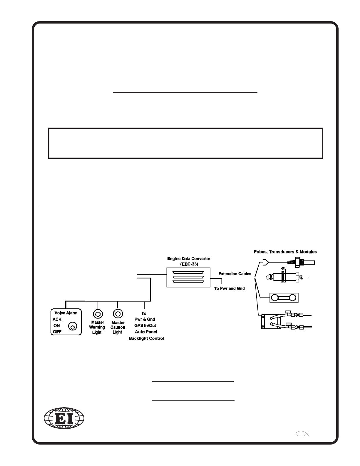
The CGR-30P Glass Panel Engine Monitor installation consists of four major components: the CGR Display,
the Engine Data Converter (EDC-33P), the Probes, Transducers & Modules, and the Wiring and Extension
Cables.
1.1.1 1.1.1
1.1.1
1.1.1 1.1.1
The CGR-30P (CGR) display measures 3.25" wide by 3.25" high by 4.36" deep and is designed to be
mounted from behind the aircraft instrument panel.
The 25-pin D-sub connector on the back of the CGR display is used to interface the CGR to the EDC-
33P, Power & Ground, GPS, Master Warning and Caution Lights and Audio Panel (experimental only).
1.1.2 1.1.2
1.1.2
1.1.2 1.1.2
The EDC-33P (Engine Data Converter, "EDC") converts all of the engine and aircraft system signals
into serial data. This data is transmitted to the CGR display via one wire 5V-Serial Bus. Up to two
EDC’s can be connected to the CGR display. The EDC measures 4.5" long by 3.5" wide by 2.2" high
and is to be mounted on cockpit side of the firewall or in an equipment bay. The EDC reduces the wire
bundle to the instrument panel by over 100 wires. There are three 37-pin D-sub connectors that interface the EDC to the various probes, transducers and modules.
1.1.3 1.1.3
1.1.3
1.1.3 1.1.3
The various probes, transducers and modules are mounted in the aircraft at appropriate locations.
CGR Display:CGR Display:
CGR Display:
CGR Display:CGR Display:
EDC-33P:EDC-33P:
EDC-33P:
EDC-33P:EDC-33P:
Probes, Transducers and Modules:Probes, Transducers and Modules:
Probes, Transducers and Modules:
Probes, Transducers and Modules:Probes, Transducers and Modules:
1.1.4 1.1.4
1.1.4
1.1.4 1.1.4
The extension cables and wiring provide the connections from the probes, modules or direct connec-
tions to the EDC inputs. Once the Wiring and Extension Cables are installed into the aircraft they
become semi-permanent. Everything else (CGR, EDC, Probes and Modules) can be easily disconnected
and removed.
Wiring & Extension Cables:Wiring & Extension Cables:
Wiring & Extension Cables:
Wiring & Extension Cables:Wiring & Extension Cables:
3
Page 13

1.2 Operational Overview:
The CGR system measures a primary engine or aircraft function using a probe or transducer and displays that
function on the CGR screen using the following steps:
A. A probe is mechanically connected to the aircraft and electrically connected to an EDC input. The
pre-wired harness provides most of the electrical connections from the probes to the EDC inputs.
B. The EDC converts the signals from the probes to a digital format and sends the data to the CGR
through the serial bus. The EDC has 33 inputs. Many of these inputs can be used to monitor various
types of functions.
C. The CGR receives the data from the EDC and the data is processed through the CGR as follows:
1. A Function is created in the CGR and is linked to an EDC input.
2. The function is assigned a screen location onto the Main or System Screen of the CGR.
3. Calibration, units, redlines, limits etc. are assigned to the data coming into that function.
Much of the setup for the certified CGR is done at the factory and cannot be changed by the pilot or installer.
See the following Password Protection Section for more information.
1.3 Installation Overview:
For a twin engine installation refer to appendix A8.0. The installer should start the installation by reviewing
the CGR and EDC Wiring Work Sheets. There are four work sheets, one for each of the 37-pin D-Sub connectors on the EDC and one for the CGR. The work sheets are packaged with each of the three EDC wire
harnesses and one for the CGR. The work sheets provide a list of the functions and probes/transducers
included with this kit. The installation is achieved by performing the following steps:
A. The CGR display is installed. The CGR is mounted from behind the instrument panel in a standard
3 1/8" hole.
B. Probes and Transducers are installed.
C. Control Panels, Pots and Warning Lights are installed.
D. The EDC is installed. The EDC should be installed on the inside of the cockpit or in an instrument
bay. For a twin-engine aircraft it can be installed on the backside (not the engine side) of the firewall.
E. The Wire Harnesses are installed. The wire harnesses for the EDC and CGR are pre-wired and in-
cluded in the kit.
F. Field Calibration/Setup steps are performed. If installed Fuel Tanks are calibrated/setup. Calibration/
Setup requires a password. See the following Password Protection section for more information.
G. System Checkout is performed.
4
Page 14

1.4 Password Protection:
The CGR provides a number of screens for the pilot to use during flight, none of which require a password. It
also provides many System Configuration Screens that are used to configure the CGR for a specific aircraft.
Fuel level, if installed, must be calibrated during installation before the aircraft is flown.
The CGR provides three levels of passwords for configuring and calibrating the unit.
1.4.1 1.4.1
1.4.1
1.4.1 1.4.1
The User Password is for the pilot or operator of the aircraft. This password allows the pilot to perform
the following:
By default the User Password is blank, if left blank you will not need to enter a password to access these
features. If the CGR installed in an aircraft that is primarily owner operated we recommend leaving the
password blank. However, if this aircraft is used by renters or students, we recommend setting a password to keep unauthorized changes from happening.
User Password:User Password:
User Password:
User Password:User Password:
A. Adjust the K-Factor for the fuel flow.
B. Set the Local and Zulu Clocks.
C. Setup some Bar Graph limits.
D. Download recorded flight log data and change recording sample rate.
E. Set the Recurring Fuel Alarm.
F. Backup Config Files.
G. Change or disable the User Password.
H. Set Com3 and Com4
I. Set the Voice Level and test a Voice File.
J. Perform the Input/Output Tests.
K. View a Function and Probe Configuration.
1.4.2 1.4.2
1.4.2
1.4.2 1.4.2
The Maintenance Password is for the installer or maintenance personnel. This password allows the
installer to perform all of User Password operations plus the following:
For a non-certified CGR, Maintenance Password is “00100.” For a certified CGR, this password will be
provided in the kit. To qualify for the maintenance password you must be a certified mechanic or a FAA
approved shop.
This password protects the CGR from unauthorized access to calibration data. If calibration data is
improperly changed, it could lead to engine or aircraft damage and/or personal injury. Once the CGR is
Maintenance Password:Maintenance Password:
Maintenance Password:
Maintenance Password:Maintenance Password:
A. Update the Software.
B. Retrieve the Config Files.
C. Change the Maintenance Password.
D. Set Tach and Engine Time.
E. Set Com1 and Com2.
F. Set the Display Backlight levels.
G. Calibrate Fuel Tanks.
5
Page 15

installed and checked out, this password should be changed (whether a certified or non-certified CGR) to
a unique number and should be protected from unauthorized access.
If the new password is lost or a new shop requires access to calibration data (as allowed by the Maintenance Password), Electronics International has a method of providing the Maintenance Password to any
authorized shop or certified mechanic.
FAA
1.4.3 1.4.3
1.4.3
1.4.3 1.4.3
The OEM Password is for OEM's or Experimental installers. This password allows access to all System
Configuration Data. For a non-certified CGR, the OEM Password is “00100.” For a certified CGR this
password is only released under a contract or agreement.
This password protects the CGR from unauthorized access to calibration data. If calibration data is
improperly changed, it could lead to engine or aircraft damage and/or personal injury. Once the CGR is
installed and checked out, this password should be changed (whether a certified or non-certified CGR) to
a unique number and should be protected from unauthorized access.
OEM/Experimental Password:OEM/Experimental Password:
OEM/Experimental Password:
OEM/Experimental Password:OEM/Experimental Password:
6
Page 16

Hardware InstallationHardware Installation
Hardware Installation
Hardware InstallationHardware Installation
2.1 Important Information and Initial Checkout:
2.2 Review the "EDC Wiring Work Sheets:"
2.3 Verify You Have all the Probes, Modules, Transducers and Cables:
2.4 Install the CGR Display:
2.5 Install the Temperature Probes:
2.6 Install the Pressure Transducers:
2.7 Install the Interface Circuit for Annunciators:
2.8 Install the CO Detector, G-Sensor and/or Other Available CGR Options:
2.02.0
2.0
2.02.0
2.9 Install the Shunt:
2.10 Install the Fuel Flow Transducer:
2.11 Install the EI P-300C Fuel Level Probes (OEM or Experimental Only):
2.12 Install the EI P-300M Fuel Level Sender:
2.13 Install the Resistive Fuel Level Module (RFLM-4-X):
2.14 Install the
2.15 Install the Intensity Control Pot (Optional):
2.16 Install the Master Warning (red) and Caution (yellow) Lights:
2.17 Installing the EDC-33P:
Voice Alarm Control Panel (OEM/Experimental Only):
7
Page 17

2.1 Important Information and Initial Checkout:
The installer and aircraft owner must read the Warranty/Agreement before starting theThe installer and aircraft owner must read the Warranty/Agreement before starting the
A.
The installer and aircraft owner must read the Warranty/Agreement before starting the
The installer and aircraft owner must read the Warranty/Agreement before starting theThe installer and aircraft owner must read the Warranty/Agreement before starting the
installation.installation.
installation. There is information in the Warranty/Agreement that may alter your decision to install
installation.installation.
this instrument.
this instrument.this instrument.
this instrument.
this instrument.this instrument.
If you are not an FAA Certified Aircraft Mechanic familiar with the issues of installing If you are not an FAA Certified Aircraft Mechanic familiar with the issues of installing
B.
If you are not an FAA Certified Aircraft Mechanic familiar with the issues of installing
If you are not an FAA Certified Aircraft Mechanic familiar with the issues of installing If you are not an FAA Certified Aircraft Mechanic familiar with the issues of installing
engine and aircraft instruments, engine and aircraft instruments,
engine and aircraft instruments,
engine and aircraft instruments, engine and aircraft instruments,
should use current aircraft standards and practices to install this instrument (refer to ACshould use current aircraft standards and practices to install this instrument (refer to AC
should use current aircraft standards and practices to install this instrument (refer to AC
should use current aircraft standards and practices to install this instrument (refer to ACshould use current aircraft standards and practices to install this instrument (refer to AC
43.13).43.13).
43.13).
43.13).43.13).
Check that any necessary FAA Approvals are available for your aircraft before startingCheck that any necessary FAA Approvals are available for your aircraft before starting
C.
Check that any necessary FAA Approvals are available for your aircraft before starting
Check that any necessary FAA Approvals are available for your aircraft before startingCheck that any necessary FAA Approvals are available for your aircraft before starting
the installation. The STC and AML is located in section 8 of this manual.the installation. The STC and AML is located in section 8 of this manual.
the installation. The STC and AML is located in section 8 of this manual.
the installation. The STC and AML is located in section 8 of this manual.the installation. The STC and AML is located in section 8 of this manual.
If you do not accept the terms of the Warranty/Agreement, do not installIf you do not accept the terms of the Warranty/Agreement, do not install
If you do not accept the terms of the Warranty/Agreement, do not install
If you do not accept the terms of the Warranty/Agreement, do not installIf you do not accept the terms of the Warranty/Agreement, do not install
Do not attempt to install this instrument.Do not attempt to install this instrument.
Do not attempt to install this instrument.
Do not attempt to install this instrument.Do not attempt to install this instrument.
The installer The installer
The installer
The installer The installer
D. Read the Installation Instructions entirely and resolve any issues you may have
installation. This may eliminate any delays once the installation is started.
E. Inspect the contents of this package prior to installation.
stalled into a certified aircraft, check that the Model Number listed on the TSO labelstalled into a certified aircraft, check that the Model Number listed on the TSO label
stalled into a certified aircraft, check that the Model Number listed on the TSO label
stalled into a certified aircraft, check that the Model Number listed on the TSO labelstalled into a certified aircraft, check that the Model Number listed on the TSO label
incorporates the Aircraft ID for which it is to be installed. Each CGR-30P display isincorporates the Aircraft ID for which it is to be installed. Each CGR-30P display is
incorporates the Aircraft ID for which it is to be installed. Each CGR-30P display is
incorporates the Aircraft ID for which it is to be installed. Each CGR-30P display isincorporates the Aircraft ID for which it is to be installed. Each CGR-30P display is
configured for a specific aircraft and should only be installed in that aircraft only.configured for a specific aircraft and should only be installed in that aircraft only.
configured for a specific aircraft and should only be installed in that aircraft only.
configured for a specific aircraft and should only be installed in that aircraft only.configured for a specific aircraft and should only be installed in that aircraft only.
Do not install a non-certified CGR in a certified aircraft.Do not install a non-certified CGR in a certified aircraft.
F.
Do not install a non-certified CGR in a certified aircraft. A certified CGR lists the applicable
Do not install a non-certified CGR in a certified aircraft.Do not install a non-certified CGR in a certified aircraft.
TSO numbers at the bottom of the Model Label attached to the back panel of the CGR.
Before starting the installation make sure the instrument will fit in the intended installa-Before starting the installation make sure the instrument will fit in the intended installa-
G.
Before starting the installation make sure the instrument will fit in the intended installa-
Before starting the installation make sure the instrument will fit in the intended installa-Before starting the installation make sure the instrument will fit in the intended installa-
tion location without obstructing the operation of any controls.tion location without obstructing the operation of any controls.
tion location without obstructing the operation of any controls. CFR 23.1321(a) states,
tion location without obstructing the operation of any controls.tion location without obstructing the operation of any controls.
“Each flight, navigation, and powerplant instrument for use by any required pilot during takeoff,
initial climb, final approach, and landing must be located so that any pilot seated at the controls can
monitor the airplane’s flight path and these instruments with minimum head and eye movement.”
AC 23.1311 provides one method (but not the only method) of complying with this CFR. AC
23.1311 recommends a powerplant instrument be installed within a distance of 21" from the pilot’s
visual centerline to the middle of the instrument. The pilot’s visual centerline is a perpendicular line
from the pilot’s eye to the instrument panel. In most aircraft, installing the CGR-30P to the right of
the Radio Stack would be acceptable. In some aircraft, the visual centerline falls to the right of the
Attitude Indicator.
If the CGR-30P system is to be in-If the CGR-30P system is to be in-
If the CGR-30P system is to be in-
If the CGR-30P system is to be in-If the CGR-30P system is to be in-
beforebefore
before starting the
beforebefore
If the powerplant instrument cannot be installed within 8" of the pilot’s visual centerline, AC 23.1311
recommends Master Caution and Warning Lights be installed. Installation of Master Caution and
Warning Lights is covered in this manual.
H. If this instrument is to replace an existing gauge in the aircraft, it is the installer’s responsibility to
move or replace any existing instruments or components in accordance with FAA approved methods
and procedures (see AC 43.13).
I. An Installation Checklist is provided to assist the installation of the CGR system. It does not replace
the instructions located in this manual.
8
Page 18

2.2 Review the "EDC Wiring Work Sheets:"
There are a number of probes and extension cables that will need to be installed. The key to keeping the
installation simple is to organize the work using the
Review the functions assigned to each EDC input on the EDC Wiring Work Sheets. The work sheets are
prepared at the factory with the functions and probes already assigned.
"EDC Wiring Work Sheets" "EDC Wiring Work Sheets"
"EDC Wiring Work Sheets" supplied with this kit.
"EDC Wiring Work Sheets" "EDC Wiring Work Sheets"
2.3 Verify You Have all the Probes, Modules, Transducers and Cables:
The three EDC 37-pin D-sub connectors and the CGR 25-pin D-sub connector are pre-wired at the factory.
The three EDC connectors are marked Top, Middle and Bottom. The EDC Wiring Work Sheets provide a
list of the probes supplied with this kit.
A. Check that you have all the probes listed on the EDC Wiring Work Sheets.
B. Check that the three EDC 37 pin-D-sub wire harnesses are provided with the proper wires for
each of the probes shown on the EDC Wiring Work Sheets.
C. Check that the CGR 25-pin D-sub wire harness is provided.
2.4 Install the CGR Display:
Before starting the installation make sure the instrument will fit in the location you intend toBefore starting the installation make sure the instrument will fit in the location you intend to
Before starting the installation make sure the instrument will fit in the location you intend to
Before starting the installation make sure the instrument will fit in the location you intend toBefore starting the installation make sure the instrument will fit in the location you intend to
install it without obstructing the operation of any controls. install it without obstructing the operation of any controls.
install it without obstructing the operation of any controls. Also, the pilot should have a clear
install it without obstructing the operation of any controls. install it without obstructing the operation of any controls.
view of the CGR display without any visual obstructions. The CGR display is installed from behind the
panel into a standard 3 1/8" hole.
CFR 23.1321(a) states, “Each flight, navigation, and powerplant instrument for use by any required pilot
during takeoff, initial climb, final approach, and landing must be located so that any pilot seated at the
controls can monitor the airplane’s flight path and these instruments with minimum head and eye move-
ment.” To comply with this requirment mount the CGR-30P 21" or less from the pilot’s visual centerline to
the middle of the instrument. The pilot’s visual centerline is a perpendicular line from the pilot’s eye to the
instrument panel. In some aircraft, the visual centerline falls to the right of the Attitude Indicator.
If the CGR display is not installed within 8" of the pilot’s visual centerline, the external Master Caution and
Warning Lights should be installed. Installation of Master Caution and Warning Lights are covered in this
manual.
9
Page 19
2.5 Install the Temperature Probes:
Install only the Temperature Probes applicable for your configuration.
A. A.
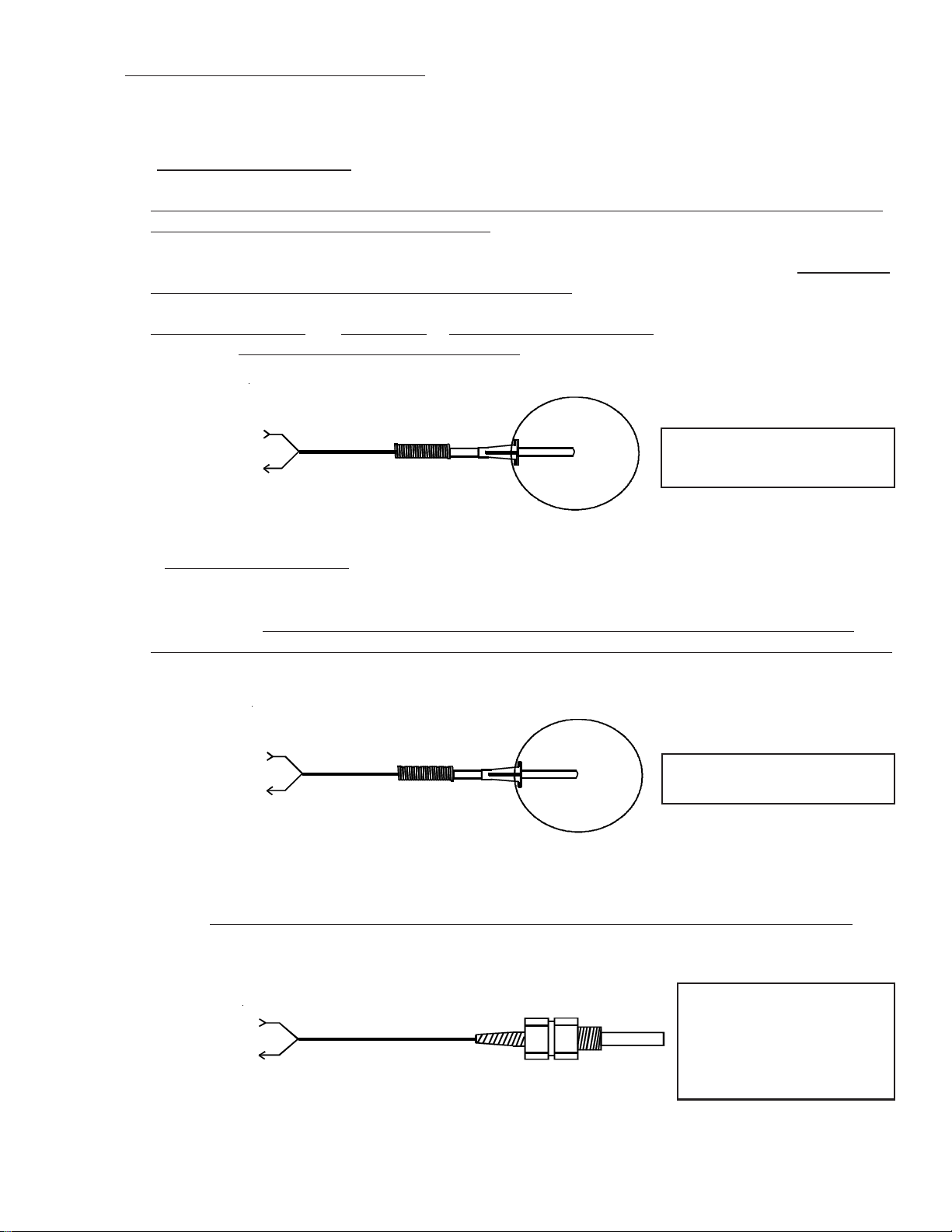
EGT Probe Installation:EGT Probe Installation:
A.
EGT Probe Installation:
A. A.
EGT Probe Installation:EGT Probe Installation:
Look at each exhaust stack and determine the best location at which all of the EGT probes can be mounted
at the same distance down from the exhaust ports. The ideal location is 1 1/2", but ease of installation should
prevail. Drill a 13/64" diameter hole in each exhaust stack. Insert the probe and tighten the hose clamp. As
the hose clamp is heated and cooled, it will become loose as it conforms to the exhaust stack. After the first
10 hours of operation, each hose clamp should be retightened.
IMPORTANT NOTE: For Cessna 210s or any aircraft having a slip joint in the exhaust system, install the
EGT probes ABOVE OR BELOW THE SLIP JOINT. Installing an EGT probe in the slip joint can damage
the probe.
To EDC
Temp Input
(Middle or Bottom
Connector)
B. B.
TIT Probe Installation:TIT Probe Installation:
B.
TIT Probe Installation:
B. B.
TIT Probe Installation:TIT Probe Installation:
The TIT probe should be installed on the inlet of the Turbocharger one to two inches before the Turbocharger flange.
should be routed away from the exhaust pipe and should not come in contact with other aircraft components.
When installing the P-110 probe, drill a 13/64" diameter hole in the exhaust stack. Insert the probe and
tighten the hose clamp.
To EDC
Temp Input
(Middle or Bottom
Connector)
If a P-111, P-112 or P-114 TIT probe is to be installed, perform the steps outlined in the “TIT Probe Depth
Adjustment Procedure” that comes with the TIT probe.
(Red)
(Yel)
Look at each exhaust stack and determine the best location to install the TIT probe. It
(Red)
(Yel)
P-110 Hose Clamp, Type K.
Used on most engines.
P-110 Hose Clamp, Type K.
Used on most engines.
NOTE: After the first 10 hours of operation, the hose clamp on the P-110 probe should be retightened. As
the hose clamp is heated and cooled, it will become loose as it conforms to the exhaust stack.
To EDC
Temp Input
(Middle or Bottom
Connector)
(Red)
(Yel)
P-111 (1/8" NPT), Type K
P-112 (7/16" -20), Type K
P-114 (1/4" NPT), Type K
Screws into a boss welded
onto the exhaust pipe.
10
Page 20
C. C.
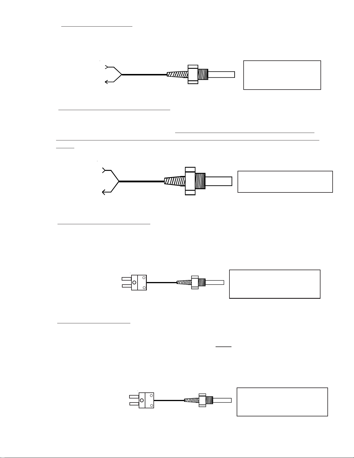
CHT Probe Installation:CHT Probe Installation:
C.
CHT Probe Installation:
C. C.
CHT Probe Installation:CHT Probe Installation:
Most engines have threaded ports for the CHT probes just below the lower spark plug. Install the CHT
probes into these threaded ports.
To EDC
Temp Input
(Middle or Bottom
Connector)
D. D.
OIL Temperature Probe Installation:OIL Temperature Probe Installation:
D.
OIL Temperature Probe Installation:
D. D.
OIL Temperature Probe Installation:OIL Temperature Probe Installation:
Oil temperature can vary throughout an engine. Your engine’s oil temperature specifications are based on a
specific location of the oil temperature probe. If the CGR is to be used as the primary oil temperature
instrument, install the oil temperature probe (P-120) in the primary oil temperature pick up point for your
engine.
To EDC
Temp Input
(Middle or Bottom
Connector)
Carb Temp Probe Installation:Carb Temp Probe Installation:
E. E.
Carb Temp Probe Installation:
E.
Carb Temp Probe Installation:Carb Temp Probe Installation:
E. E.
(Red)
(Yel)
(Red)
(Yel)
P-100 CHT Probe,
3/8" -24, Type K. Used on
most engines.
P-120 Oil Temp Probe, 5/8" -18,
Type K. Used on most engines.
Remove the threaded plug located in the carburetor housing just below the throttle valve. Install the Carburetor Temperature Probe (P-128) in this hole using a lock washer. Care should be taken not to over-tighten
the probe, thereby stripping the threads in the carburetor housing.
To EDC
Temp Input
(Middle Connector, Ch 8
Recommended)
OAT Probe Installation:OAT Probe Installation:
F. F.
OAT Probe Installation:
F.
OAT Probe Installation:OAT Probe Installation:
F. F.
Mount the OAT Probe in an appropriate location on the aircraft, using the hardware supplied. The OAT
Probe is sensitive to air temperature changes. For this reason,
the cowl or engine exiting air (i.e., on the belly of the aircraft). Also, if the probe is mounted in the cowling
area near a turbo or hot cylinder head, radiant heat may influence the probe temperature. Other than these
considerations, the OAT Probe may be mounted in an air intake vent, on the side of the cowling or anywhere
else on the aircraft.
To EDC
Temp Input
(Middle Connector, Ch 8
Recommended)
P-128 Carb Temp / OAT Probe,
1/4" -28, Type K. Used on most
engines.
do not mount the OAT probe in the path of
P-128 Carb Temp / OAT Probe,
1/4" -28, Type K. Used on most
engines.
11
Page 21
G. G.
Other Temperature Probe Installation:Other Temperature Probe Installation:
G.
Other Temperature Probe Installation:
G. G.
Other Temperature Probe Installation:Other Temperature Probe Installation:
Other temperature probes (Cowl Temp, CDI Temp, Water Temp, etc.) may be installed using current
aircraft standards and practices (refer to AC 43.13). Make sure these probes do not interfere with the
operation of the engine or aircraft.
2.6 Install the Pressure Transducers:
Install only the Pressure Transducers applicable for your configuration.
A. A.
Manifold Pressure Transducer Installation:Manifold Pressure Transducer Installation:
A.
Manifold Pressure Transducer Installation:
A. A.
Manifold Pressure Transducer Installation:Manifold Pressure Transducer Installation:
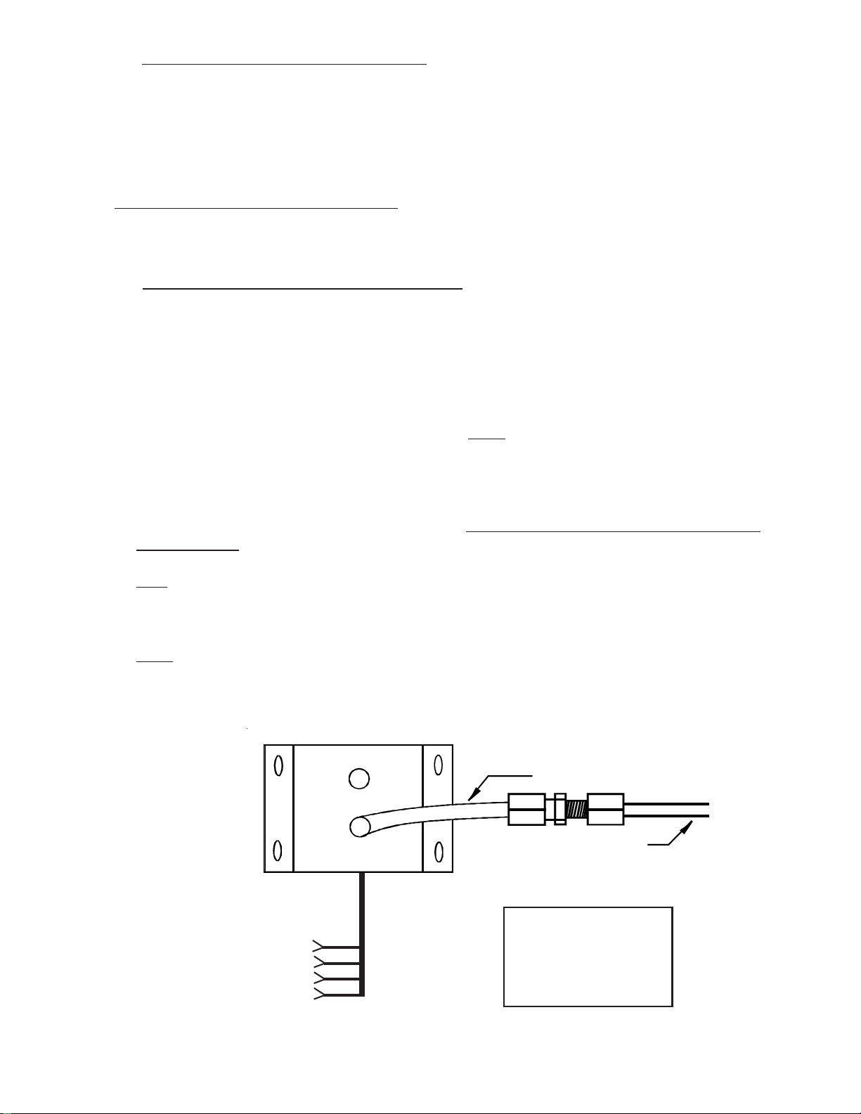
Mount the PT-30ABS Pressure Transducer on the inside firewall or in the equipment bay under the aircraft
instrument panel. Use the holes in the bottom plate to mount the PT-30ABS. Only two mounting holes are
required.
An equipment bay can be made from a sheet of aluminum. Any piece of equipment or module used with the
CGR-30P can be mounted on the aluminum sheet using a Nut Plate or Riv-Nut to allow easy installation and
removal. The aluminum sheet is then mounted to the
should never have to be removed. Many aircraft are designed with an equipment bay.
inside firewall of the aircraft (using short spacers) and
Connect the aircraft manifold pressure line to the pressure port on the PT-30ABS Pressure Transducer. A
flare or barb fitting may be used to connect these lines. Care should be taken not to put excess pressure on
the flexible line leading to the pressure transducer. Make sure there are no kinks in the flexible
pressure lines.
Note: Many certified aircraft have a very small hole in the manifold pressure line to create airflow back to
the intake manifold. This small flow of air keeps fuel from working its way into the manifold pressure
gauge (or transducer), which can cause damage to the transducer over time.
Note: The PT-30ABS can measure manifold pressure up to 36.0" Hg. For manifold pressures above 36.0"
Hg. use the PT-60ABS pressure transducer.
.170" ID Flexible Tube
Aircraft M.P. Line
To EDC
Press Input
(Top Connector)
(Red)
(Blk)
(Grn)
(Wht)
The PT-30ABS, Pressure Transducer is used
on most engines for
Manifold Pressure (0 to
36" Hg.).
12
Page 22
B. B.
Gyro Vacuum Pressure Transducer Installation:Gyro Vacuum Pressure Transducer Installation:
B.
Gyro Vacuum Pressure Transducer Installation:
B. B.
Gyro Vacuum Pressure Transducer Installation:Gyro Vacuum Pressure Transducer Installation:
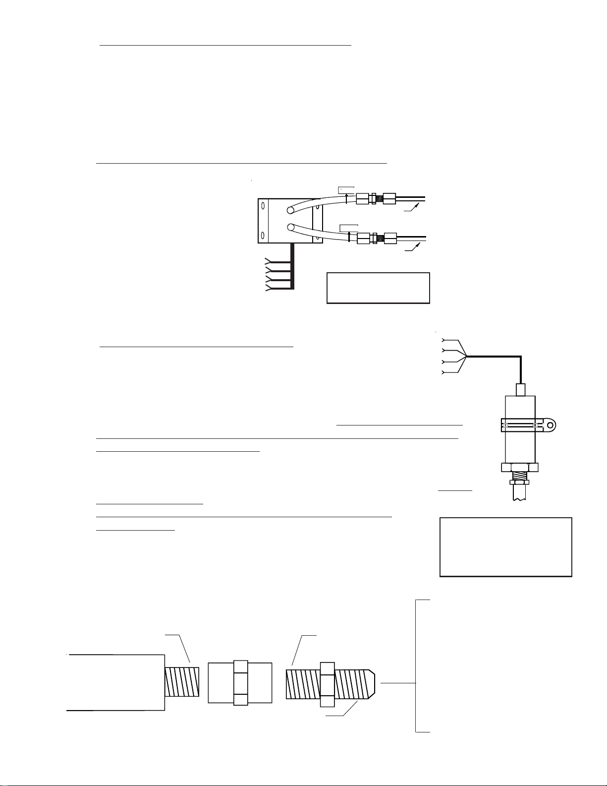
Mount the PT-05Diff Pressure Transducer on the inside firewall or in the equipment bay under the aircraft
instrument panel. Use the holes in the bottom plate to mount the PT-05Diff. Only two mounting holes are
required.
Connect the aircraft gyro vacuum line to the port tagged "Vac" on the PT-05Diff. Connect the port tagged
"Press" to the aircraft overboard pressure line. A flare or barb fitting may be used to connect these lines.
Care should be taken not to put excess pressure on the flexible line leading to the pressure transducer.
Make sure there are no kinks in the flexible pressure lines.
PRESS
Overboard Pressure Line
VAC
Gyro Vacuum Line
To EDC
Press Input
(Top Connector)
(Red)
(Blk)
(Grn)
(Wht)
The PT-05Diff, Pressure
Transducer (0 to 6" Hg)
C. C.
Oil Pressure Transducer Installation:Oil Pressure Transducer Installation:
C.
Oil Pressure Transducer Installation:
C. C.
Oil Pressure Transducer Installation:Oil Pressure Transducer Installation:
Find a convenient location on the firewall or a
To EDC
Press Input
(Top Connector)
(Red)
(Blk)
(Grn)
(Wht)
bracket and mount the pressure transducer with the
clamp provided. The oil pressure line does not have
to be routed into the cabin area, although you will need access on the cabin side of the
firewall to tighten the pressure transducer clamp nut. Do not mount the pressure
transducer to an engine baffle or directly on the engine with the transducer
supported by an adapter or fitting. Vibration can cause the adapter to break,
resulting in loss of engine oil. The pressure transducer is equipped with an 1/8" NPT
male port. This port can be adapted to any oil pressure line. Use only a flexible hose
and fittings suitable for aircraft use. Route a flexible oil pressure line from the primary
oil pressure pickup point to the pressure transducer and tighten all fittings.
Do not use the case of the pressure transducer to tighten the
pressure fittings. Maintain any restrictive orifice currently in the system.
Some fittings you may want to consider using are listed below:
*
1/8 NPT Male
PT-100GA
1/8 NPT
Coupler
1/8 NPT Male
The PT-100GA Pressure
Transducer is used on
most engines for pressures
up to 120 psi.
#2 Straight - AN816-2D
#3 Straight - AN816-3D
#4 Straight - AN816-4D
#2 45' - MS20823-2D
#3 45' - MS20823-3D
#4 45' - MS20823-4D
AN910-1D
Flare
13
#2 90' - MS20822-2D
#3 90' - MS20822-3D
#4 90' - MS20822-4D
*
Page 23
D. D.
Fuel Pressure Transducer Installation:Fuel Pressure Transducer Installation:
D.
Fuel Pressure Transducer Installation:
D. D.
Fuel Pressure Transducer Installation:Fuel Pressure Transducer Installation:
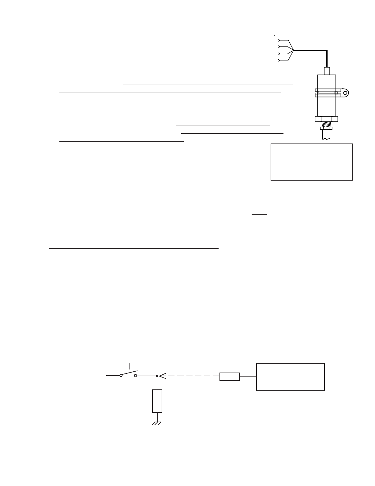
Find a convenient location on the firewall or a bracket
and mount the pressure transducer with the clamp
provided. The fuel pressure line does not have to be
routed into the cabin area although you will need access
on the cabin side of the firewall to tighten the pressure
transducer clamp nut. Do not mount the pressure transducer to an engine baffle
or directly onto the engine with the transducer supported by an adapter or
fitting. Vibration can cause the adapter to break, resulting in loss of engine fuel. The
pressure transducer is equipped with a 1/8" NPT male port. This port can be adapted to
any fuel pressure line. Use only a flexible hose and fittings suitable for aircraft use.
Route a flexible fuel pressure line from the primary fuel pressure pick up point to the
pressure transducer and tighten all fittings. Do not use the case of the pressure
transducer to tighten the pressure fittings. Maintain any restrictive
orifice currently in the system.
* Some fittings you may want to consider using are listed above.
E. E.
Other Pressure Transducer Installations:Other Pressure Transducer Installations:
E.
Other Pressure Transducer Installations:
E. E.
Other Pressure Transducer Installations:Other Pressure Transducer Installations:
Other pressure transducers should be mounted in the aircraft in the same manner as the Gyro Vacuum
Transducer or the Oil and Fuel Pressure Transducers, as appropriate. Note: Any unused + or -
pressure inputs must be wired to a ground pin on the EDC 37-pin connector.
To EDC
Press Input
(Top Connector)
(Red)
(Blk)
(Grn)
(Wht)
The PT-30GA Pressure
Transducer is used on most
engines for pressures up to
40 psi.
2.7 Install the Interface Circuit for Annunciators:
Any Temperature or Resistive Fuel Level channel on the EDC may be used to monitor the state of a
switch, relay or output from a device. This output can be used to trigger a light (annunciator) on the
CGR. Annunciator lights such as Canopy Latch, Baggage Door, Deice, Pitot Heat, Fire, etc. can be
displayed on the Main or System screen on the CGR.
To monitor a voltage, a VI-221 (Voltage Interface Unit) will be required. This consists of a 221K
ohm resistor heat shrunk between two wires with a D-Sub pin crimped on one end. The following
methods may be used to interface an EDC channel (using a VI-221) to a switch, relay or device:
A. A.
Monitoring a Signal That Switches Between Any Voltage and Ground:Monitoring a Signal That Switches Between Any Voltage and Ground:
A.
Monitoring a Signal That Switches Between Any Voltage and Ground:
A. A.
Monitoring a Signal That Switches Between Any Voltage and Ground:Monitoring a Signal That Switches Between Any Voltage and Ground:
Device, Switch or Relay
EDC
Bus or any Voltage
VI-221
Load
Temp or Resistive Fuel
Level Channel.
14
Page 24

Monitoring a Signal that is Switched to Ground:Monitoring a Signal that is Switched to Ground:
B. B.
Monitoring a Signal that is Switched to Ground:
B.
Monitoring a Signal that is Switched to Ground:Monitoring a Signal that is Switched to Ground:
B. B.
Bus
If a Load does not exist,
an additional VI-221
must be placed in the
circuit as shown. This
provides a pullup for the
switch.
VI-221
Light, Horn, etc.
Load
Device, Switch or
Relay
VI-221
EDC
Temp or Resistive Fuel
Level Channel.
2.8 Install the CO Detector, G-Sensor and/or Other Available CGR Options:
The CO Guardian Remote Mounted CO Detector, G-Sensor and other CGR options listed on EI’s price sheet are
provided with there own installation instructions. These items should be installed and wired in accordance with the
accompanying instructions. Note: The CO Detector connects to Port 4 or Port 3 Input on the CGR.
2.9 Install the Shunt:
An external shunt is a strip of metal, usually mounted on a bakelite base. This metal is made of special alloys to
produce a very small, precise signal when current passes through it. It is not affected by temperature changes.
If your aircraft currently has an external shunt you can calibrate your CGR to that shunt. The CGR can be
calibrated to match any shunt on the market.
A. A.
Determine How the Shunt willDetermine How the Shunt will
A.
Determine How the Shunt will
A. A.
Determine How the Shunt willDetermine How the Shunt will
be Installed in the Aircraft’sbe Installed in the Aircraft’s
be Installed in the Aircraft’s
be Installed in the Aircraft’sbe Installed in the Aircraft’s
Electrical System:Electrical System:
Electrical System:
Electrical System:Electrical System:
There are two common methods of
installing a shunt in an aircraft. One
method is with the shunt in the
alternator lead. The other method is
with the shunt located in the battery
lead. The S-50 shunt that comes with
the CGR-30 package may be installed
Installation Method Advantages Disadvantages
Battery Lead: 1. Shows load current on the
gro und ( e ngine o ff) a nd dur ing
an alternator failure.
2. A ll War ning Lights a r e
operational.
Alternator Lead: 1. Shows load current during
flight or w he n t he e ngine is
running.
2. A ll War ning Lights a r e
operational.
1. Cannot show load current during
flight or w he n t he e ngine is r unning.
1. Cannot show load current when
the e ngine is o ff o r during an
alternator failure.
S0224921
using either method. The advantages
and disadvantages of each method are listed below.
There are few disadvantages with either method. Although EI’s test pilot has a slight preference for
the alternator lead when using the CGR, ease of installation should be the determining factor in this
installation. If more than one shunt is required, a second shunt can be installed through a FM-VA-M(50 or 300) Functional Module. The Functional Modules come with their own installation instructions.
15
Page 25

B. B.
Install the External Shunt:Install the External Shunt:
B.
Install the External Shunt:
B. B.
Install the External Shunt:Install the External Shunt:
The external shunt should be installed in an appropriate location that
minimizes the routing of main cables (refer to figure 1 or 2 as appropriate
for your installation). It should also be mounted in a location where
inadvertent damage cannot occur. If the shunt can be accessed easily, it
should be covered. When mounting the shunt, use self-locking or safetywired nuts.
The signal wires from the shunt to the EDC must be fused a short distance
after they leave the shunt. If this is a new installation, install two in-line one-amp fuses, one in each
of the signal lines from the shunt to the EDC Amp Input.
Note: Note:
Note: If you are replacing an existing ammeter, the shunt may already be mounted in the aircraft. If
Note: Note:
you already have a shunt installed and know the value of the existing shunt, the CGR can be calibrated to that shunt.
Figure 1: Figure 1:
Figure 1:
Figure 1: Figure 1:
External Shunt Installed in the Battery LeadExternal Shunt Installed in the Battery Lead
External Shunt Installed in the Battery Lead
External Shunt Installed in the Battery LeadExternal Shunt Installed in the Battery Lead
To Voltage Regulator
Master Switch
Contactor
F
Alternator
B
G
Shunt
Batt.
Starter Solenoid
To Starter
Note: The External ShuntNote: The External Shunt
Note: The External Shunt
Note: The External ShuntNote: The External Shunt
should not be installed in seriesshould not be installed in series
should not be installed in series
should not be installed in seriesshould not be installed in series
with the starting current.with the starting current.
with the starting current.
with the starting current.with the starting current.
This line may be connected currently
to the Master Switch Contactor or the
Starter Solenoid. In either case it
should be rerouted to the Bus or + side
of the Shunt.
-
External Shunt
This is the main lead going to the Bus. It may come from
the Master Switch Contactor or the Starter Solenoid.
+
B
U
S
16
Page 26

Figure 2: Figure 2:
Figure 2:
Figure 2: Figure 2:
External Shunt Installed in the Alternator LeadExternal Shunt Installed in the Alternator Lead
External Shunt Installed in the Alternator Lead
External Shunt Installed in the Alternator LeadExternal Shunt Installed in the Alternator Lead
Alternator
F
Batt.
To Starter
G
B
Reverse Current Diode.
(Some aircraft do not have this
diode)
Master Switch
Contactor
Starter Solenoid
This line may be connected to the Bus, Master
Switch Contactor or the Starter Solenoid.
External Shunt
+
-
Note: The Shunt may be installed
before or after any reverse
current diode. However, it is
preferable to install it after the
reverse current diode as shown.
This is the main lead going to the Bus.
It may come from the Master Switch
Contactor or the Starter Solenoid.
B
U
S
2.10 Install the Fuel Flow Transducer:
Mount the Fuel Flow Transducer using the appropriate drawing found on the following pages.
Ai rcraft Co nfi gurat i o n Draw i ng #
Fuel injected engine without a fuel return line
from the fuel servo (most Lycomings).
Fuel injected engine with a fuel return line from
the fuel servo (most C ontinentals).
C a r b ur eted e ngine w ith a fue l p ump a nd no fue l
return line.
Carbureted engine with a fuel pump and a fuel
return line (requires a n FFDM- 1 Mo dule).
Carbureted engine with a gravity feed fuel
system (requires a n FT- 90 F low Tra nsducer).
1229932 or
1229931
0415941
1229932 or
1229931
1229932 or
1229931, and
1015941
1229932 or
1229931
17
Fuel Flow Transducer Selection:
FT-60 (Red Cube): For 0 to 350 HP
Engines.
FT-90 (Gold Cube): For 350 to 550
HP Engines.
FT-180 (Black Cube): For 550+ HP
Engines.
(See the transducer specification for
pressure drops at a given flow rate.)
Page 27

Note:Note:
Note: If your engine is equipped with a pressure carburetor with a fuel return line
Note:Note:
back to the fuel tank, you will need to install two flow transducers: one in the feed line from the fuel
pump to the carburetor and one in the return line from the carburetor back to the fuel tank. Also, a Fuel
Flow Differential Module (FFDM-1) will need to be installed. See drawings 1229932 and 1015941 on
the following pages.
from the carburetor
Note: Note:
Note:
Note: Note:
A.A.
A. The transducer output port should be mounted lower, even with or no more than 4" per foot higher
A.A.
Note: • The direction of the flow of
• Mount the transducer with
Insure the fuel flow transducer is appropriate for the horsepower of the engineInsure the fuel flow transducer is appropriate for the horsepower of the engine
Insure the fuel flow transducer is appropriate for the horsepower of the engine.
Insure the fuel flow transducer is appropriate for the horsepower of the engineInsure the fuel flow transducer is appropriate for the horsepower of the engine
than the carburetor inlet port (or fuel servo on a fuel-injected engine). If this is not possible, a loop
should be put in the fuel line between the Fuel Flow Transducer and the carburetor or fuel servo (see
diagram below). This loop is intended to vacate air and keep it from getting trapped in the fuel
transducer.
End ViewEnd View
End View
End ViewEnd View
fuel through the transducer
is marked on the transducer.
the wires pointing up, or
the cap with five bolts
pointing up or the output
pointing up or any combination thereof.
Fuel Flow
Transducer
If the transducer is more than 4" per foot higher
than the carburetor or fuel servo port, put a loop
in the fuel line between the transducer and the
carburetor or fuel servo. This will allow bubbles
to vacate the Flow Transducer.
Side ViewSide View
Side View
Side ViewSide View
OUT
1/4" NPT
B. B.
B. Do not remove the yellow caps on the flow transducer until the fuel hoses are ready to be installed.
B. B.
C. C.
C. The flow of fuel through the transducer must follow the direction marked on the transducer.
C. C.
D. D.
D. The flow transducer must be mounted so the wires exiting the transducer are pointing up, or the cap
D. D.
with five bolts is pointing up, or the output port is pointing up, or any combination thereof.
E. E.
E. Before connecting any hoses, thoroughly clean them and insure they are free of any loose material.
E. E.
High air pressure may be used,
flow transducer.flow transducer.
flow transducer.
flow transducer.flow transducer.
F.F.
F. When mounting a Fuel Flow Transducer, make provisions for the Fuel Pressure Transducer as neces-
F.F.
sary.
however, however,
however,
however, however,
do not allow high air pressure to pass through thedo not allow high air pressure to pass through the
do not allow high air pressure to pass through the
do not allow high air pressure to pass through thedo not allow high air pressure to pass through the
Fuel Flow Transducer
Carburetor or
Fuel Servo
18
Page 28

You may want to consider using some fittings and hoses shown below. Note:
torque of 15 ft. lbs. or screw the fittings tighter than two full turns past hand tight, which-torque of 15 ft. lbs. or screw the fittings tighter than two full turns past hand tight, which-
torque of 15 ft. lbs. or screw the fittings tighter than two full turns past hand tight, which-
torque of 15 ft. lbs. or screw the fittings tighter than two full turns past hand tight, which-torque of 15 ft. lbs. or screw the fittings tighter than two full turns past hand tight, whichever happens first.ever happens first.
ever happens first.
ever happens first.ever happens first.
Hose Fittings:Hose Fittings:
Hose Fittings:
Hose Fittings:Hose Fittings:
1/4" NPT1/4" NPT
1/4" NPT
1/4" NPT1/4" NPT
Fittings:Fittings:
Fittings:
Fittings:Fittings:
FlareFlare
Flare
FlareFlare
FlareFlare
Flare
FlareFlare
DO NOT EXCEED aDO NOT EXCEED a
DO NOT EXCEED a
DO NOT EXCEED aDO NOT EXCEED a
HoseHose
Hose
HoseHose
#4 Straight - AN816-4-4D
#6 Straight - AN816-6D
#8 Straight - AN816-7D
#6 45' - MS20823-6D
#4 90' - MS20822-4-4D
#6 90' - MS20822-6D
Straight - MS24587-XX, Stratoflex 300-, Aeroquip 40045' - MS27226-XX, Stratoflex 646- and 640, Aeroquip 980006
90' - MS27224-XX, Stratoflex 649- and 643, Aeroquip 980005
NOTE: NOTE:
NOTE: The Stratoflex teflon hose can be much more flexible
NOTE: NOTE:
and easier to route than most existing hoses. If you have a hardto-fit installation, you might want to consider this hose.
19
Page 29

Fuel Flow Transducer
To the Carburetor
(or Fuel Servo)
(OUT)
Adapter, (1/4" NPT to Fuel Hose)
Mounting Procedure:
1. Find a convenient location within 6" of a hose support or fitting and away from any hot exhaust
pipes to suspend the Fuel Flow Transducer. The hose support or fitting may be on the input or
output line of the Flow Transducer and the support may be to an adjacent hose.
2. Remove the fuel hose which goes from the Fuel Pump (or the Fuel Filter on a gravity feed system) to
the Carburetor (or Fuel Servo).
3. Purchase two new hoses: one to be used from the fuel pump (or the Fuel Filter) to the Fuel Flow
Transducer and the other to be used from the Fuel Flow Transducer to the carburetor (or Fuel
Servo). There must be flexible hose in and out of the Transducer. The hoses must meet TSOC53a Type C or D FAA specifications. The new hoses must be the same size as the current
hoses in the aircraft. Sources of fittings and fabricated hoses are:
(IN)
From the Fuel Pump
(or Fuel Filter on a
gravity feed system)
6" Maximum from
support or fitting.
Sacramento Sky Ranch Inc.
(916) 421-7672
OR
Fax: (916) 421-5719
4. Mount the Fuel Flow Transducer in the fuel line.
Varga Enterprises Inc.
(602) 963-6936
FAX: (602) 899-0324
You must use the FT-90 (Gold Cube) Fuel
OR
Hoses Unlimited Inc.
(510) 483-8521
Fax: (510) 483-8524
Flow Transducer on a gravity feed system or for any engine over 350 H.P. If the Transducer is mounted within 6" of an exhaust pipe, the Flow Transducer must be wrapped
with Fire Sleeving.
Read the Installation Instructions for important installation considerations.Read the Installation Instructions for important installation considerations.
5.
Read the Installation Instructions for important installation considerations.
Read the Installation Instructions for important installation considerations.Read the Installation Instructions for important installation considerations.
Drawn By:
Electronics International Inc.Electronics International Inc.
Electronics International Inc.
R.R.
Approved By:
R.R.
Scale:
Electronics International Inc.Electronics International Inc.
Installation of a Fuel Flow Transducer suspended in the fuel
line from the fuel pump to the carburetor or fuel servo.
None
Material:
Next Assembly:
P/N:
Note: Not applicable for a fuel-injected engine with a fuel
return line (see D/N 0415941).
Date: Rev:
12/29/93
D: 7/2/02
D/N:
12299321229932
1229932
12299321229932
20
Page 30

Fuel Flow Transducer
To the Carburetor
(or Fuel Servo)
Adapter, (1/4" NPT to Fuel Hose)
Mounting Procedure:
1. Find a convenient location on the firewall (away from any hot exhaust pipes) and mount a bracket
for the Fuel Flow Transducer. Check both sides of the firewall for clearance before drilling any
holes.
2. Mount the Fuel Flow Transducer onto the Bracket. You must use the FT-90 (Gold Cube) Fuel
Flow Transducer on a gravity feed system or for any engine over 350 H.P. If the Transducer is mounted within 6" of an exhaust pipe, the Flow Transducer must be wrapped with
Fire Sleeving.
3. Remove the fuel hose which goes from the Fuel Pump (or the Fuel Filter on a gravity feed system) to
the Carburetor (or Fuel Servo).
(OUT)
(IN)
Bracket
From the Fuel Pump
(or Fuel Filter on a
gravity feed system).
Adapter, (1/4 NPT to Fuel Hose)
4. Purchase two new hoses, one to be used from the fuel pump (or the Fuel Filter) to the Fuel Flow
Transducer (making provisions for the fuel pressure transducer as necessary) and the other to be used
from the Fuel Flow Transducer to the carburetor (or Fuel Servo). There must be flexible hose in
and out of the Transducer. The hoses must meet TSO-C53a Type C or D FAA specifications.
The new hoses must be the same size as the current hoses in the aircraft. Sources of fittings
and fabricated hoses are:
Sacramento Sky Ranch Inc.
(916) 421-7672
OROR
OR
OROR
Fax: (916) 421-5719
Read the Installation Instructions for important installation considerations.
5.
Drawn By:
R.R.
Approved By:
R.R.
Scale:
Varga Enterprises Inc.
(602) 963-6936
OROR
OR
OROR
FAX: (602) 899-0324
Electronics International Inc.Electronics International Inc.
Electronics International Inc.
Electronics International Inc.Electronics International Inc.
Installation of a Fuel Flow Transducer on the Firewall and in
the fuel line from the fuel pump to the carburetor or fuel servo.
Hoses Unlimited Inc.
(510) 483-8521
Fax: (510) 483-8524
None
Material:
Next Assembly:
Note: Not applicable for a fuel-injected engine with a fuel
return line (see D/N 0415941).
P/N:
Date: Rev:
12/29/93
21
D: 7/2/02
D/N:
12299311229931
1229931
12299311229931
Page 31

To the Flow Divider
Mounting Procedure:
1. Find a convenient location between the Fuel Servo and Flow
Divider and away from any hot exhaust pipes to suspend the
Fuel Flow Transducer. The Transducer must mounted within
6" of a hose support or fitting. The support or fitting may be
on the input or output line of the Flow Transducer and the
support may be to an adjacent hose.
2. Remove the fuel hose which goes from the Fuel Servo to the
Flow Divider.
3. Purchase two new hoses: one to be used from the Fuel Servo
to the Fuel Flow Transducer and the other to be used from the
Fuel Flow Transducer to the Flow Divider. There must be
flexible hose in and out of the Fuel Transducer. The hoses
must meet TSO-C53a Type C or D FAA specifications. The
new hoses must be the same size as the current hoses in
the aircraft. Sources of fittings and fabricated hoses are:
Sacramento Sky Ranch Inc.
(916) 421-7672
Fax: (916) 421-5719
OROR
OR
OROR
Varga Enterprises Inc.
(602) 963-6936
FAX: (602) 899-0324
OROR
OR
OROR
Adapter, (1/4" NPT
to Fuel Hose)
(OUT)
(IN)
From the Fuel Servo
Hoses Unlimited Inc.
(510) 483-8521
Fax: (510) 483-8524
4. Mount the Fuel Flow Transducer in the fuel line. You must use the FT-90 (Gold Cube) Fuel Flow Trans-
ducer on any engine over 350 H.P. If the Transducer is mounted within 6" of an exhaust pipe, the
Flow Transducer must be wrapped with Fire Sleeving.
5. Read the Installation Instructions for important installation considerations.
Drawn By:
Electronics International Inc.Electronics International Inc.
Electronics International Inc.
R. R.
Approved By:
R.R.
Scale:
Electronics International Inc.Electronics International Inc.
Installation of the Fuel Flow Transducer suspended in the fuel
line between the Fuel Servo and the Flow Divider.
None
Material:
Next Assembly:
P/N:
Note: Only applicable for installation on aircraft with a fuel
return line from the Fuel Servo.
Date: Rev:
4/15/94
B: 7/2/02
D/N:
04159410415941
0415941
04159410415941
22
Page 32

Fuel Flow Transducer
To the Fuel Tank
(OUT)
Adapter, (1/4" NPT to Fuel Hose)
Mounting Procedure:
1. Find a convenient location within 6" of a hose support or fitting and away from any hot exhaust
pipes to suspend the Fuel Flow Transducer. The hose support or fitting may be on the input or
output line of the Flow Transducer and the support may be to an adjacent hose.
2. Remove the return fuel hose which goes from the Carburetor to the Fuel Tank.
3. Purchase two new hoses: one to be used from the Carburetor to the Fuel Flow Transducer and the
other to be used from the Fuel Flow Transducer to the Fuel Tank. There must be flexible hose
in and out of the Transducer. The hoses must meet TSO-C53a Type C or D FAA specifications.
The new hoses must be the same size as the current hose in the aircraft. Sources of fittings
and fabricated hoses are:
(IN)
Fuel return line from
the Carburetor
6" Maximum from
support or fitting
Sacramento Sky Ranch Inc.
(916) 421-7672
OR
Fax: (916) 421-5719
4. Mount the Fuel Flow Transducer in the fuel return line.
Varga Enterprises Inc.
(602) 963-6936
FAX: (602) 899-0324
You must use the FT-90 (Gold Cube
OR
Hoses Unlimited Inc.
(510) 483-8521
Fax: (510) 483-8524
Fuel Flow Transducer on any engine over 350 H.P. If the Transducer is mounted within
6" of an exhaust pipe, the Flow Transducer must be wrapped with Fire Sleeving.
5. Read the Installation Instructions for important installation considerations.
Drawn By:
R.R.
Approved By:
R.R.
Scale:
Electronics International Inc.
Installation of a Fuel Flow Transducer suspended in the fuel
return line from the carburetor to the fuel tank.
None
Material:
Next A ssembly:
Note: Only applicable for installation on aircraft with a fuel
return line from the Carburetor.
P/N: Date: Rev: D/N:
10/15/94
A: 7/2/02
23
10159411015941
1015941
10159411015941
Page 33

2.11 Install the EI P-300C Fuel Level Probes (OEM or Expermintal Only):
Install the P-300C (Capacitive) Fuel Level Probes in accordance with the aircraft manufacturer’s instructions.
2.12 Install the EI P-300M Fuel Level Sender:
The CGR-30 system can interface with an aircraft’s existing Resistive Fuel Sensors via the RFLM-4 or these
resistive fuel level sensors can be replaced with the P-300M (Magnetic Float) Fuel Level Sender. The signal
produced by the P-300M Sender is a linear voltage output designed to work with the CGR-30 system.
The P-300M’s float arm and travel must match the aircraft’s existing sender’s arm and travel. Due to the lack
of information from aircraft manufacturers, the existing sender may need to be removed from the aircraft and
sent to Electronics International. In this way the P-300M’s float arm and travel can be matched with the
aircraft’s existing sender. Contact Electronics International for further information.
The P-300M has the same bolt pattern as resistive fuel senders. The P-300M requires three wires to interface
to the EDC (resistive senders only use one wire).
Note:Note:
Note: Calibrating the CGR-30P to a fuel tank can compensate for nonlinearity in the tank’s shape and
Note:Note:
nonlinearity in the resistive fuel level sensor. The CGR cannot correct for inconsistent or non-repeatable
signals from resistive fuel level senders. Unfortunately, many older resistive fuel level senders (and in some
cases, newer resistive senders) exhibit some of the following problems:
- Variation in the wiper-to-element resistance (CRV).
- Stick slip problems with bearings and wiper-to-element contact.
- Windup causing jumps in readings.
- Weak wiper tension.
- Loose or worn bearings, causing fluctuations in tension and resistance.
- Worn out wiper.
- Corroded wiper.
- Corroded or worn element.
- Build up of varnish on the wiper and element.
- Water logged floats.
If you find inconsistent or inaccurate fuel level readings (due to a defective resistive fuel level sender), you
must have the sender replaced. Inaccurate readings can lead to a dangerous situation.
on the fuel level sender for accurate fuel level information. Read the “Important Notice” in the CGR Operating Instructions.
The P-300M is a float type fuel level sender that uses a magnet and pickup device to detect the float position
and produce the signal for the CGR-30 system. The P-300M has no wiper or resistive element and there is no
tension on the bearing surfaces. It is not subject to the many problems associated with resistive type senders.
The P-300M has nothing to wear out or affect inaccurate fuel level readings. Also, the P-300M does not
require electricity to flow through an element and wiper saturated in fuel, as is the case with resistive senders.
The CGR-30P depends
24
Page 34

2.13 Install the Resistive Fuel Level Module (RFLM-4-X):
The RFLM-4 is a Resistive Fuel Level Module that provides pull-up resistors for 4
resistive fuel level sensors. This module is required to interface an EDC Resistive
Fuel Level Input to a Resistive Fuel Sensor.
Warring:Warring:
Warring: DO NOT connect an RFLM-4 to the output of an existing aircraft’s
Warring:Warring:
Capacitive System, damage to the system may occur. The small output voltage of
an existing capacitive system currently drives a fuel level gauge. This output
wire should be routed to one of the resistive fuel level inputs on the EDC with NO
connection to an RFLM unit.
There are two RFLM-4 modules available. The RFLM-4-12V operates
on a 12-volt electrical system and the RFLM-4-24V operates on a 24volt electrical system.
Mount the RFLM-4-X to the inside firewall or to an equipment bay
under the aircraft instrument panel. Use the holes in the bottom plate
to mount the unit. Only two mounting holes are required.
Note: For each Fuel Level Channel on the EDC you can use either the Resistive Input or the Capacitive Input, but
not both.
The appropriate model must be used.
To EDC Resistive Fuel
Level Inputs (Bottom Connector)
and the Fuel Level Sensor.
2.14 Install the Voice Alarm Control Panel (OEM or Experimental Only):
If the voice alarms provided by the CGR are to be
used, the AV-17CP Control Panel will need to be
installed in the aircraft instrument panel.
To CGR
A. Locate the Control Panel and Switch in the
AV-17CP packet. Find an appropriate
mounting location on the aircraft instrument panel for the Control Panel and
Switch. The Switch will require a 3/4" clearance behind the aircraft instrument panel.
B. Using the AV-17CP Control Panel as a template, mark the aircraft instrument panel and drill a 1/4"
hole for the AV-17CP Switch.
C. Mount the Switch from behind the aircraft instrument panel. Be careful not to damage the
silkscreening on the Control Panel. The Switch must be mounted with the
The lock washer should be mounted on the Switch and behind the aircraft instrument panel.
White/Orange
White/Red
White/Brown
(OFF)
(+5V)
(ACK)
AV-17CP, Control Panel
white/orange wire upwhite/orange wire up
white/orange wire up
white/orange wire upwhite/orange wire up
2.15 Install the Intensity Control Pot (Optional):
..
.
..
The backlight display intensity of the CGR is controlled by an external source. The CGR will work with any
rheostat and with any voltage swing. The input voltage levels for a bright and dim setting are programmable.
If a rheostat is not currently installed in the aircraft, Electronics International's Intensity Control Pot (CP-1) can
be installed.
25
Page 35

A. Find an appropriate mounting location on the
aircraft instrument panel for the CP-1 Control Pot.
Aircraft Instrument Panel
Nut
The Pot will require a 2" clearance behind the
aircraft instrument panel.
B. Mark the aircraft instrument panel and drill a 1/4"
hole for the Pot.
Knob
C. Mount the Pot from behind the aircraft instrument
CP-1
panel and install the knob.
2.16 Install the Master Warning (red) and Caution (yellow) Lights:
Pot
To CGR
(Wht/Orng)
1/4" Hole
The Warning and Caution Lights do not have to be installed unless the CGR is
installed more than 8" from the pilot’s visual centerline.
A. Locate the Red (AL-1R) and Yellow (AL-1Y) lights in the kit. Find an
appropriate mounting location within 8" of the pilot's visual centerline.
The lights will require 3/4" clearance behind the aircraft instrument
panel.
To CGR
To CGR
B. The CGR-30P remote lights and placard must be installed in a location
where the placard will be readable in all lighting conditions. Installing the annunciators near an
exiting lighting source or installing a post light are acceptable methods of compliance, other methods
may also be acceptable.
C. Mark the aircraft instrument panel and drill a 5/16" hole for each light. Install the Red Warning Light
and the Yellow Caution Light from behind the aircraft instrument panel.
Note: If the CGR Master Warning and Caution Outputs are connected to other lights or devices, the
current must be limited to 0.1 amps. The outputs pull to ground when active.
2.17 Install the EDC-33P:
Top
(Red)
To Bus
(Yellow)
To Bus
The EDC-33P (Engine Data Converter) converts all of the analog
engine signals into serial data which is output to the CGR display via
one wire (5V Serial). The EDC unit measures 4.5" long by 3.5" wide
by 2.2" high. There are three 37-pin D-sub connectors that interface
to the various probes, modules or direct connections to the aircraft.
Mount the EDC on the inside firewall under the aircraft instrument panel or in an equipment bay. For a twinengine aircraft the EDC can be mounted on the opposite side of the firewall of the engine or in the cabin or
equipment bay. Use the holes in the bottom plate of the EDC to mount the unit. Be sure you will have enough
room to connect the three D-sub connector wire harnesses to the EDC. Note: If you run out of channels on the
EDC, a second EDC may be installed and connected to the CGR.
When routing the EDC wire harnesses refer to the Top, Middle and Bottom "EDC Wiring Work Sheets" found
at the back of this manual. Insure no wires obstruct the freedom of travel of any controls.
26
Page 36

Install the EDC Wire HarnessesInstall the EDC Wire Harnesses
Install the EDC Wire Harnesses
Install the EDC Wire HarnessesInstall the EDC Wire Harnesses
andand
and
andand
Route WiresRoute Wires
Route Wires
Route WiresRoute Wires
3.1 Attach the three EDC 37-pin Wire Harnesses to the EDC:
3.2 Connect the EDC Harness to the Temperature Probes:
3.3 Connect the EDC Harness to the Pressure Transducers:
3.4 Connect the EDC Harness to the Shunt:
3.5 Connect the EDC Harness to the Fuel Flow Transducer:
3.6 Connect the EDC Harness to the Existing Capacitive Fuel Level System:
3.03.0
3.0
3.03.0
3.7 Connect the RFLM-4-x Harness to the EDC Connector and to the Resistive Fuel
Level Sensors:
3.8 Connect the EDC Harness to the EI P-300C Capacitive Fuel Level Probes:
3.9 Connect the EDC Harness to the EI P-300M Magnetic Fuel Level Senders:
3.10 Connect the EDC Harness (Volts Measurement Pin) to the Bus:
3.11 Connect the EDC Harness to the RPM Signals:
3.12 Set up the EDC for a 4 or 6-Cylinder Engine:
3.13 Connect the EDC Harness to the VI-221's (Voltage Interface Units):
3.14 Connect the EDC Harness to Power and Ground:
3.15 Route the EDC 5V-Serial Wire to the CGR Connector:
27
Page 37

3.1 Attach the three EDC 37-pin Wire Harnesses to the EDC:
Secure the connectors using the supplied mounting screws.
3.2 Connect the EDC Harness to the Temperature Probes:
Route each of the temperature cables in the EDC harness to the appropriate temperature probe. Cut the wires
to length, install the appropriate connectors (see the “Working with Connectors” section of this manual for
more information) and connect to the temperature probe. When connecting to a temperature probe, leave some
slack in the cable exiting the probe to prevent damage to the probe over time.
All Type K Temperature Probes
E
DC
Temp Input
(1 of 17)
(Red)
(Yel)
Middle or Bottom Connector
All E.I. Temperature
Probes are Type K.
3.3 Connect the EDC Harness to the Pressure Transducers:
Route each of the pressure cables in the EDC harness to the appropriate pressure transducers. Cut the wires to
length, install the appropriate connectors (see the “Working with Connectors” section of this manual for more
information) and connect to the pressure transducer. When connecting to a pressure transducer, leave some
slack in the cable exiting the transducer to prevent future damage to the transducer.
PT-30GA, PT-100GA, PT300GA, PT-3000S
Pressure Transducers:
(Red)
(Blk)
(Grn)
(Wht)
PT-30ABS, PT-60ABS, PT-05Diff, PT-04H20
Pressure Transducers:
EDC
Press Input
(1 of 6)
Top Connector
28
EDC
Press Input
(1 of 6)
Top Connector
(Red)
(Blk)
(Grn)
(Wht)
Page 38

3.4 Connect the EDC Harness to the Shunt:
Route the EDC Amps wires to the Shunt. The way the Shunt is installed in the aircraft determines which lug
will be used as "+" (see “Installing the Shunt” in the previous section of this manual). The EDC +Amp Input
wire (orange) should be connected to the small lug on the "+" side of the Shunt. The EDC -Amp Input wire
(brown) should be connected to the small lug on the "-" side of the Shunt.
3.5 Connect the EDC Harness to the Fuel Flow Transducer:
Route the fuel flow cable in the EDC harness to the Fuel Flow Transducer. Cut the wires to length, install the
appropriate connectors (see the “Working with Connectors” section of this manual for more information) and
connect to the fuel flow transducer. When connecting to the Fuel Flow Transducer, leave some slack in the
cable exiting the transducer to prevent future damage to the transducer.
FT-60, FT-90, FT-180
Fuel Flow Transducers:
EDC
Fuel Flow Input
(1ea.)
Top Connector
+10V, (Red, pin 15)
Gnd, (Blk, pin 16)
Signal (Wht, pin 14)
3.6 Connect the EDC Harness to the Existing Capacitive Fuel Level System:
The output signal of a capacitive fuel level system (on a certified aircraft) will have a wire connected from the
capacitive system to the fuel level gauge. The signal on this wire will be 0 to approx 150mV DC. The other
side of the gauge will be grounded. Re-route the signal wire (currently connected to the fuel level gauge) to
one of the resistive inputs on the bottom connector of the EDC. DO NOT connect an RFLM unit into this
system, damage to the system may occur. The current fuel level gauge must be remove from the system.
A 332-ohm resistor should be connected from the signal wire to ground. For a CGR-30 STC’d system, this
resistor is integrated into the wire harness supplied with the system.
EDC
Resistive Fuel Level
(4ea.)
Bottom Connector
Rin
Gnd
332-Ohms
29
To Capacitive Signal Out
(0 to approx 150 mV)
Page 39

3.7 Connect the RFLM-4-x Harness to the EDC Connector and to the Resistive Fuel
Level Sensors:
DO NOT connect the RFLM into a capacitive system, damage may occur. Route the appropriate resistive fuel
level input wires (for the number of tanks to be monitored) in the RFLM-4-x harness to the EDC Bottom
Connector. Plug the wires into the appropriate resistive fuel level channels. The excessive wire can be cut and
spliced, bundled and tie wrapped up or cut to length and new D-Sub pin installed (see the “Working with
Connectors” section of this manual for more information). Route and connect the corresponding wires in the
RFLM-4-x wire harness to the appropriate fuel tank sensors. Route the red wire (in pin 1 of the RFLM-4-x
connector) to the aircraft bus via the CGR/EDC 5-amp circuit breaker.
RFLM-4-12V (for a 12Volt system)
RFLM-4-24V (for a 24Volt system)
Fuel Tank
1
Fuel Tank
Connect only the wires for
which you have Fuel Tanks.
2
Fuel Tank
EDC
Resistive Input
(1 of 4)
Bottom Connector
Ch 1 Rin, Pin 2 (Brown)
Ch 2 Rin, Pin 3 (Orange)
Ch 3 Rin, Pin 4 (Yellow)
Ch 4 Rin, Pin 5 (Green)
Ch 1 Rin, Pin 6 (Brown)
Ch 2 Rin, Pin 7 (Orange)
Ch 3 Rin, Pin 8 (Yellow)
Ch 4 Rin, Pin 9 (Green)
3
Fuel Tank
4
+Vin, Pin 1, (Red)
To Bus (via CGR/EDC Circuit Breaker)
3.8 Connect the EDC Harness to the EI P-300C Capacitive Fuel Level Probes:
Route the appropriate capacitive fuel level wires (for the number of tanks to be monitored) in the EDC harnesses to the capacitive fuel level probes. Cut the wires to length, install the appropriate connectors (see the
“Working with Connectors” section of this manual for more information) and connect to the capacitive fuel
level probe.
EDC
Capacitive Input
(1 of 4)
Bottom Connector
+5V (Red)
Gnd (Black)
Cin (White)
P-300C Capacitive
Fuel Level Probe
Note: The capacitive fuel level channels are shared with the resistive channels. A single capacitive
and resistive channel cannot be used simultaneously.
30
Page 40

3.9 Connect the EDC Harness to the EI P-300M Magnetic Fuel Level Senders:
Route the appropriate fuel level wires (for the number of tanks to be monitored) in the EDC harnesses to the
P-300M magnetic fuel level senders. Cut the wires to length, install the appropriate conntectors and connect to
the P-300M fuel level sender.
EDC
Resistive Input
(1 of 4)
Bottom Connector
+5V (Red)
Gnd (Black)
Rin (White)
.
.
Fuel Tank 4
Fuel Tank
1
P-300M
Fuel Level Sensor
3.10 Connect the EDC Harness (Volts Measurement Pin) to the Bus:
Pin 35 of the EDC top connector monitors bus voltage. Connect this pin to the bus to be monitored.
3.11 Connect the EDC Harness to the RPM Signals:
To P-lead
If the EDC RPM Ch 1 and Ch 2 Inputs are to be connected to a Magneto, Ignition Coil
or CDI Ignition System, connect the Ring Terminal Isolators (found in the RPM Isolator
packet) to the P-leads on the back of the Mag Switch. Connect the EDC RPM Ch 1 and
Ch 2 wires (White/Brown and White/Orange) to the RPM Isolators.
If the EDC RPM Ch 1 and Ch 2 Inputs are to be connected to an electronic ignition
system, connect the EDC RPM Ch 1 and Ch 2 wires (White/Brown and White/Orange)
directly to the electronic ignition system RPM output (do not use any isolators). Without isolators the EDC RPM Ch 1 and Ch 2 Inputs have a 3-volt trigger level and will
accommodate 0 to 5-volt, 0 to 12-volt or 0 to 24-volt signals. If only one RPM signal is
available, connect only one of the EDC RPM channels.
RPM Input
Bottom Connector
WARANING: Connecting an EDC RPM input directly to a magneto without an Isolator
will damage the EDC. Be sure there is an Isolator in each RPM input lead connected to a magneto, ignition coil or
CDI ignition.
Ring
Terminal
Isolator
(1 of 2)
EDC
(1 of 2)
3.12 Set up the EDC for a 4 or 6-Cylinder Engine:
If the EDC-33P is to be used on a 6-cylinder engine, strap pin 28 to Pin 27 on the EDC Bottom Connector.
Leave these pins open for a 4-cylinder engine. This strap may already be installed or can be found in the kit.
3.13 Connect the EDC Harness to the VI-221's (Voltage Interface Units):
Route the appropriate EDC wire to the VI-221’s that were used to interface the Gear Position Lights, Unsafe
Light, Flap Position, Trim Position and/or any indicator to the EDC.
EDC
VI-221
31
Temp or Resistive Fuel
Level Channel.
Page 41

3.14 Connect the EDC Harness to Power and Ground:
Route the power wire (Top Connector, pin 37, Red Wire) to the CGR/EDC 5-amp Circuit Breaker. Route the
ground wire (Top Connector, pin 19, Black Wire) to the aircraft ground.
WARNING: The power wire is RED and is connected to pin 37 on the EDC Top Connector. If aircraft power is
connected to any pin on the EDC other than pin 37, damage to the EDC and any connected transducers may occur.
Insure power is provided on pin 37 of the EDC Top Connector before attaching the connector.
EDC-33P
Top
To Aircraft Ground
To the CGR/EDC 5-amp Circuit Breaker
CGR-30
5V-Serial Output (pin 6)
Top Connector
Pin 37, Red Wire
Pin 19 Black Wire
Pin 18, White/Green Wire
3.15 Route the EDC 5V-Serial Wire to the CGR Connector:
Route the 5V-Serial white/green wire to the CGR connector. This wire will be connected to the CGR 5V-Serial
input in a later step. If a second EDC is installed, see the Appendix for connection information.
When routing the CGR wire harness refer to the "CGR-30 25-pin D-Sub Connector Wiring Diagram" found at
the back of this manual. Insure no wires obstruct the freedom of travel of any controls.
32
Page 42

Install the CGR Wire Harness
and
Route the Wires
4.1 Attach the CGR 25-pin D-sub Connector to the CGR:
4.2 Connect the EDC 5V-Serial Output Wire to the CGR 5V-Serial Input Wire:
4.3 Connect the CGR Harness to the Master Warning and Caution Lights:
4.4 Connect the CGR Harness to the Voice Alarm Control Panel (AV-17CP):
4.5 Connect the CGR Harness to the Audio Panel (OEM/Experimental):
4.6 Connect the CGR Harness to the Backlight Control Pot:
4.0
4.7 Connect the CGR Harness to the Moving Map Data Out from the GPS:
4.8 Connect the CGR Harness to the Fuel Data Input on the GPS:
4.9 Connect the CGR Harness to Power and Ground:
4.10 Connect the CGR Harness to the CO-Guardian CO Detector:
33
Page 43

4.1 Attach the CGR 25-pin D-sub Connector to the CGR:
Secure the connector using the supplied mounting screws.
4.2 Connect the EDC 5V-Serial Output Wire to the CGR 5V-Serial Input Wire:
Route the EDC 5V-Serial output wire to the back of the CGR Display, cut the wires to length and splice them to
the appropriate CGR 5V-Serial input wire.
4.3 Connect the CGR Harness to the Master Warning and Caution Lights:
If the Warning and Caution Lights are installed, route the CGR Master Warning Out wire (White/Yellow, Pin
10) to the Master Warning (Red) Light (AL-1R) White/Yellow wire, cut the wires to length, install the appropri-
ate connector and connect to the AL-1R.
Route the CGR Master Caution Out wire (White/Yellow, Pin 23) to the Master Caution (Yellow) Light (AL-1Y)
White/Yellow wire, cut the wires to length, install the appropriate connector and connect to the AL-1Y.
CGR-30
Red
Wht/Yel Red
Pin 10
Wht/Yel Red
Yel
To CGR/EDC
Pin 23
5-amp Circuit
Breaker
4.4 Connect the CGR Harness to the Voice Alarm Control Panel (OEM/Experimen-
tal):
If the voice alarms provided by the CGR are to be used, route the three CGR Voice Control wires to the AV17CP, cut the wires to length, install the appropriate connectors and connect to the AV-17CP.
CGR
Voice Control
Inputs
25
White/Orange
13
White/Red
White/Brown
12
(OFF)
(+3.3V)
(ACK)
34
Control Panel
(AV-17CP)
Page 44

4.5 Connect the CGR Harness to the Audio Panel (OEM/Experimental):
If the voice alarms provided by the CGR are to be used, route the two CGR Voice Warning Out wires to the
Audio Panel, cut the wires to length and connect to the Audio Panel Aux input and ground. If an audio input is
not available on the Audio Panel (or an Audio Panel is not installed) you can connect the CGR Voice Warning
Out wires to the pilot headset jack. With this installation a 49.9 ohm 1/4 watt resistor will need to be installed
in series with the CGR +Voice Warning Out wire and the audio feed wire to the jack.
Pilot's Audio Jack
-Voice
Gnd
(Wht/Gray, Pin 24)
CGR
Voice Output
+Voice
Audio Feed (from Radios)
(Wht/Blue, Pin 11)
49.9 Ohms
4.6 Connect the CGR Harness to the Backlight Control Pot:
Route the CGR Back Light Control Input wire (orange) to the aircrafts existing backlight control pot, cut the
wires to length, install the appropriate connector and connect to the pot.
4.7 Connect the CGR Harness to the Moving Map Data Out from the GPS:
If the CGR is to provide fuel data to the current way point, route the CGR "Moving Map Data In" wire (green
wire in a 4 wire cable) to the Moving Map Data Output Port on the GPS. Cut the wire to length, install the
appropriate connector and connect to the GPS port.
4.8 Connect the CGR Harness to the Fuel Data Input on the GPS:
If the GPS is capable of displaying fuel data and this feature is to be used, route the CGR "Fuel Data Out" wire
(white wire in a 4-wire cable) to the Fuel Data Input Port on the GPS. Cut the wire to length, install the appropriate connector and connect to the GPS port.
CGR
GPS Input &
Output
Moving Map Data In (Grn, Pin 3)
Fuel Flow Data Out (Wht, Pin 15)
Wire Cable
GPS
35
Page 45

4.9 Connect the CGR Harness to Power and Ground:
Route the power wire (red) to the main bus via a 5-amp Circuit Breaker. Route the ground wire (black) to the
aircraft ground.
WARNING: The power wire is RED and is connected to pin 1 and 2 on the CGR. If aircraft power is connected
to any pin on the CGR other than pin 1 and 2, damage to the CGR and any connected hardware may occur. Insure
power is provided on pin 1 and 2 of the CGR before attaching the connector.
CGR
Power & Ground
Power (Red, Pin 1)
Gnd (Black, Pin 14)
To Main Bus via 5-amp Breaker.
To Aircraft Ground.
4.10 Connect the CGR Harness to the CO-Guardian CO Detector:
If a CO detector was installed, connect the RS232 output from the Remote Mounted 353-201 (experimental
only) or 452-201-011 (certified) CO Detector to Pin 11 (Port 3 In) on the CGR. Refer to CO-Guardian’s
installation instructions for further information on the CO Detector.
36
Page 46

Mandatory System Setup and Checkout
5.1 Power-On Checkout:
5.2 Perform all Steps listed in the "CGR-30P Setup Checklist":
5.3 Ground Run Checkout:
5.4 First Flight Checkout:
5.5 Read the "Warranty/Agreement" and the "Important Notice":
5.0
37
Page 47

5.1 Power-On Checkout:
Turn the aircraft master switch on. The CGR will power up and perform a system test. After approximately 14
seconds the CGR will display the “Main Engine” screen with an Add Fuel Message. Press any button to
continue. If you have a problem with any of the following steps, see the Troubleshooting section of this
manual. Perform only the checks applicable to your configuration.
A. Check the RPM for a reading of 000.
B. Check the M.P. for the following reading:
Current BARO less 0.1"Hg for every 100 feet elevation above sea level.
C. Check Fuel Flow for a reading of 00.0.
D. Check Oil Pressure for a reading of 00.
E. Check Oil Temp to read near ambient temperature.
F. Check Volts for proper reading.
G. Check Amps for proper reading.
H. Check all EGT’s to read near ambient temperature.
I. Check all CHT’s to read near ambient temperature.
J. Check OAT to read ambient temperature.
K. Check all Annunciators for proper operation.
L. Check all other functions on the Main and System screen to operate properly.
M. Check aircraft instruments for any EMI interferance.
Note:Note:
Note: Fuel Level may not read properly until they have been calibrated.
Note:Note:
5.2 Perform all Steps listed in the "CGR-30P Setup Checklist":
A Setup Checklist is provided on blue tag board. Each step listed in this checklist must be completed before
continuing with this installation.
5.3 Ground Run Checkout:
Start the aircraft engine. Check that the values for each function displayed on the CGR are proper for "engine
on" operation. Any problem with a specific function will be associated with a probe, cable or interconnect
cable between the probe and the EDC for that function. If you have a problem with any of the following steps,
see the Troubleshooting section of this manual. Perform only the checks applicable to your configuration.
A. Check the RPM.
B. Check the M.P.
C. Check Fuel Flow.
D. Check Oil Pressure.
E. Check Oil Temperature.
F. Check Fuel Level for each Tank.
G. Check Volts.
H. Check Amps.
I. Check all EGTs.
J. Check all CHTs.
K. Check OAT.
L. Check all Annunciators.
M. Check all other functions on the Main and System screen.
38
Page 48

Turn the engine off. Inspect the entire system to be certain there is no interference with controls. Also, check
for loose fittings, proper connections, clamps, probes, and inspect for leaks, chafing, obstructions, heat damage
Check that all fittings are tight.Check that all fittings are tight.
and anything that may cause unsafe flight.
engine and/or aircraft damage and possibly personal injury.
Check that all fittings are tight.
Check that all fittings are tight.Check that all fittings are tight.
Loose fitting can cause
5.4 First Flight Checkout:
Prepare the aircraft for flight. Fly the aircraft in the pattern. Check for proper operation of each function
displayed on the CGR. Land the aircraft and perform the following checks as soon as possible:
A. Check all fittings, hoses and transducers for leaks.
B. Check all fittings, hoses, wires, system components and hardware to be secure and not chaffing.
C. Check for interference to any controls.
D. Check for any unsafe condition.
Do not release the aircraft for normal operation until all steps in this document have been performed and the
aircraft is safe to fly.
5.5 Read the "Warranty/Agreement" and the "Important Notice":
Require the pilot to read the "Warranty/Agreement" and the "Important Notice" located in the front of the
"Operating Instructions" before releasing the aircraft for flight.
39
Page 49

Installation Data
6.1 Instructions for Continued Airworthiness (ICA):
6.2 Airworthiness Limitations:
6.3 Installing a D-sub Pin onto a TC or Tin Copper Wire:
CGR-30P, 25-pin D-sub Connector, Wiring Diagram
EDC Wiring Work Sheet, Top Connector (Back View)
EDC Wiring Work Sheet, Middle Connector (Back View)
EDC Wiring Work Sheet, Middle Connector (Back View)
6.0
EDC Template
40
Page 50

6.1 Instructions for Continued Airworthiness (ICA):
The Instructions for Continued Airworthiness (ICA) are located in the Electronics International document
06211301 "CGR-30P Instructions for Continued Airworthiness". If you need an additional copy of the CGR30P ICA please visit: www.Buy-Ei.com or call (541) 318-6060.
6.2 Airworthiness Limitations:
The Airworthiness Limitations section is FAA approved and specifies maintenance required under CFR 43.16 and
91.403 of the Code of Federal Aviation Regulations unless an alternative program has been FAA approved.
Operational:
The conditions and tests required for TSO approval of the CGR-30 are minimum performance standards. It is the responsibility of those installing this system either on or within a specific type or class
of aircraft to determine that the aircraft installation conditions are within the TSO standards. TSO
articles must have separate approval for installation in an aircraft. The CGR-30 may be installed only
if performed under 14 CFR part 43 or the applicable airworthiness requirements. There are no further
specific operating limitations of this system.
Installation:
The CGR-30 system is to be installed in accordance with the current CGR-30 Installation Instructions,
AC 43.13 and any other appropriate FAA approved practices or guidelines. These instructions along
with FAA approved material insure the system will meet the requirements of the applicable TSOs
once installed in an aircraft. There are no further specific installation limitations of this system.
6.3 Installing a D-sub Pin onto a TC or Tin Copper Wire:
D-sub pins are used in D-sub connectors found on the EDC and the CGR. Most of these pins have already been
installed on the appropriate wires and inserted into the proper connector. To install a D-sub pin requires a D-sub
crimp tool. Most electronic stores carry a reasonably priced D-sub crimp tool. This tool will work for installing Dsub pins onto tin copper wire but it may not make good crimps on 24 ga. thermocouple wire. A pull test can be
performed to test the crimp. A ratcheting crimp tool from Tyco (P/N: 91503-1) will crimp both TC and Tin Copper Wire. All crimps must pass a 3 to 4 pound pull test to be considered reliable. To install a D-sub pin onto a 20
ga. Tin Copper Wire, perform the following steps:
A. Strip the insulation back 1/8.” Be careful not to knick the wire.
B. Insert the pin into the 24 ga. D-sub Pin Crimper. The crimpers have
two cavities; the smaller one is used to crimp the bare wire and the
slightly larger one is used to crimp around the insulation. Check that
the pin is inserted into the crimpers properly. Also, the ears on the pin
must be facing into the center of the crimp tool cavity to produce a
good crimp. If the pin rotates even a little during crimping, the
connection will be unreliable.
the D-sub Pin in the Crimp Tool
Pin Ears face Down
End View
of
Crimp Cavity
41
Page 51

C. Insert the wire into the pin. Check that the insulation is in the strain relief crimp area but not in the bare
wire crimp area. Crimp the pin onto the wire.
will cause jumpy readings and are the biggest source of problemswill cause jumpy readings and are the biggest source of problems
will cause jumpy readings and are the biggest source of problems
will cause jumpy readings and are the biggest source of problemswill cause jumpy readings and are the biggest source of problems
A good crimp is very importantA good crimp is very important
A good crimp is very important
A good crimp is very importantA good crimp is very important
..
.
..
. .
Poor crimpsPoor crimps
.
Poor crimps
. .
Poor crimpsPoor crimps
Insulation
Bare Wire
E.I. D-sub Pin
D. Pull Test: Pull (approximately 3 to 4 pounds) on the wire near the connector with one hand while
holding the connector with the other hand. If the wire pulls out of the connector, you must start over
using a new connector.
well soldered connection at the crimp can be reliable. Soldering a TC wire requires a lot of heat to
E. A
produce a good solder connection. Also, when soldering a TC wire each wire should be scraped with
a knife to expose fresh metal just before crimping and applying solder. Fluxing the TC wire can also
help. Do not use acid core solder or acid flux.
42
Page 52

CGR-30P
13
25
CGR-30P
Work Sheet
(DB25 Connector)
Back View, Wire Side
DB-25 (421-0331-00)
Pin (421-0301-00)
Aircraft ID:
SAMPLE
1
14
CGR-30P
Power In
Gnd 14
Port 1, Rx, 5V-Serial 6
Port 1, Tx, RS232
Port 2, Rx, 5V-Serial 7
Port 2, Tx, RS232 19
Port 3, Rx, RS232 3
Port 3, Tx, RS232 15
Port 4, Rx, RS232
Port 4, Tx, RS232 16
Master Warning Out 10
Master Caution Out
18
Gnd 5
Gnd 17
23
Gnd 20
DB-25
3'
1
3'
3'
4
3'
3'
Wht/Yel
Yel
Red
To 12/24 Volt Bus via MVP Breaker
Blk
To Chassis Ground
Wht/Grn
(Tx) - 2nd EDC
(Rx) - RTDO
Red
N/C
Grn
(Tx) - GPS Moving Map, CO Guardian
Wht
(Rx) - GPS Fuel Flow
Blk
N/C
(Tx) - GPS Moving Map, CO Guardian
(Rx) - GPS Fuel Flow Data
AL-1R (Red)
Wht/Yel
Wht/Yel
Red
Red
AL-1Y (Yel)
DB-37
Top Connector
18
Optional
Optional
To 12/24 Volt Bus via MVP Breaker
EDC-33P-4/6
(Tx) - 5V-Serial
Voice Control Ack 12
Voice Control +3.3V 13
Voice Control Off
Voice Warning Out + 11
Voice Warning Out - 24
Back Light Control In
USB +5V
USB +
USB -
USB Gnd
25
21
22
Wht/Brn
Wht/Red
Wht/Org
Wht/Blu
Wht/Gry
2
9
8
Wht/Org
Red
Grn
Wht
Blk
Voice Alarm
ACK
ON
OFF
To Audio Panel Aux Input
To Audio Panel Ground
To Back Light Control Pot Out
AV-17CP
Control Panel
USB
Optional
Electronics International inc.
56
43
Page 53

EDC-33P
Notes:
*1 Unused Pressure Channel
Inputs Must Be Grounded.
EDC Work Sheet
Top Connector
DB-37 Back View, Wire Side
20
1
DB-37 (421-0337-00)
Pin (421-0301-00)
37
19
Aircraft ID:
Sample
DB-25
CGR-30
EDC-33P
Fuel Flow
Pressure Ch1
Pressure Ch2
Pressure Ch3
Pressure Ch4
37
Power
19
Gnd
(Tx) - 5V-Serial 18
RS422 -B Out
+ Amps
- Amps
Signal In
+ Sigal In
- Signal In
Extra Gnd
+ Signal In
- Signal In
+ Signal In
- Signal In
+ Signal In
- Signal In
Volts
+10V
Gnd 16
+5V 20
Gnd 21
+5V
Gnd 23
+5V 24
Gnd 25
+5V 26
Gnd 27
36
35
32
33
15
14
22
DB-37
3
2
1
5
4
7
6
9
8
Red
3'
Blk
Wht/Grn
Wht/Red
3'
Org
Brn
6'
6'
3'
6'
6'
3'
To 12/24 Volt Bus via MVP Breaker
To Chassis Ground
To Aircraft Bus to be Measured (via breaker)
Existing Inline Fuses
Red
Blk
Wht
Red
Blk
Grn
Wht
Red
Blk
Grn
Wht
Red
Blk
Grn
Wht
Red
Blk
Grn
Wht
PT-05Diff
S-50 Shunt
PT- 30ABS
Flow Transducer
FT-60
PT- 30GA
PT- 100GA
Port 1, Rx
6
5V-Serial
Amps
Fuel Flow
M.P.
Fuel Pressure
Oil Pressure
Vac
Pressure Ch5
Pressure Ch6
+5V 28
Gnd
+ Signal In
- Signal In
+5V 30
Gnd 31
+ Signal In
- Signal In
Do Not Use
Do Not Use
29
11
10
13
12
*1
*1
17
34
Electronics International inc.
44
Page 54

EDC-33P-4/6
EDC Work Sheet
Aircraft ID:
Notes:
*1 Unused Pressure Channel
Inputs Must Be Grounded.
-- Extra Gnds maybe used
for shields.
-- Unused Temp Channels
may be used for annunciators.
EDC-33P
Extra Gnd
Temp Ch 1
Temp Ch 2
Temp Ch 3
Temp Ch 4
Temp Ch 5
Temp Ch 6
Temp Ch 7
Temp Ch 8
(Best for OAT)
+ In (Yel)
- In (Red)
+ In (Yel) 3
- In (Red)
+ In (Yel) 4
- In (Red)
+ In (Yel)
+ In (Yel)
- In (Red)
+ In (Yel) 7
- In (Red)
+ In (Yel) 8
- In (Red)
+ In (Yel)
Temp Comp + In 10
Extra Gnd
Extra Gnd
Gnd
DB-37
1
2
20
21
22
5
23- In (Red)
6
24
25
26
9
27- In (Red)
28
11
12
Middle Connector
DB-37 Back View, Wire Side
20
1
DB-37 (421-0337-00)
Pin (421-0301-00)
6'
6'
6'
6'
6'
6'
6'
6'
TC Extension Wire
TC Extension Wire
TC Extension Wire
TC Extension Wire
TC Extension Wire
TC Extension Wire
TC Extension Wire
TC Extension Wire
Temp Comp Diode Network (TCD-1)
(Do Not Remove)
Yel
Red
Yel
Red
Yel
Red
Yel
Red
Yel
Red
Yel
Yel
Red
Yel
37
19
P-120
P-128
P-110
P-110
P-110Red
P-110Red
SAMPLE
EGT 1P-110
EGT 2
EGT 3
EGT 4
EGT 5P-110
EGT 6
Oil Temp
OAT
Temp Ch 9
Temp Ch 10
Temp Ch 11
Temp Ch 12
Temp Ch 13
Temp Ch 14
Temp Ch 15
+ In (Yel) 13
- In (Red)
Extra Gnd
Extra Gnd
+ In (Yel)
- In (Red)
+ In (Yel)
+ In (Yel) 16
- In (Red)
+ In (Yel)
- In (Red)
+ In (Yel)
+ In (Yel)
- In (Red)
18
31
29
30
14
32
15
33- In (Red)
34
17
35
36- In (Red)
19
37
6'
6'
6'
6'
6'
6'
TC Extension Wire
TC Extension Wire
TC Extension Wire
TC Extension Wire
TC Extension Wire
TC Extension Wire
Yel
Red
Yel
Red
Yel
Red
Yel
Red
Yel
Red
Yel
Red
45
CHT 1P-100
CHT 2P-100
P-100
P-100
CHT 3
CHT 4P-100
CHT 5
CHT 6P-100
Electronics International inc.
Page 55

EDC-33P-4/6
Notes:
*1 Unused Pressure Channel
Inputs Must Be Grounded.
-- Extra Gnds maybe used
for shelds.
-- Unused Res Fuel Level Ch's
may be used for annunciators.
EDC-33P
Extra Gnd
Resistive Input
Fuel Level Ch1
Capacitive In
+5V
Gnd
24
23
21
22
20
DB-37
EDC Work Sheet
Bottom Connector
DB-37 Back View, Wire Side
20
1
DB-37 (421-0337-00)
Pin (421-0301-00)
To Bus via
MVP Breaker
Ch1
37
19
RFLM-4-24
Resistive Float Interface
DB-9M Connector (421-0343-00)
Pin (421-0301-00)
12 345678
Aircraft ID:
SAMPLE
9
Ch1
Existing
Resistive Float
L Main
Fuel Level Ch2
Fuel Level Ch3
Fuel Level Ch4
Short Pin 27 to 28 for 6-Cyl
Open for 4-Cyl
Temp Ch 16
Temp Ch 17
Extra Gnd
+5V
Gnd
Capacitive In
Extra Gnd
Extra Gnd
+5V
Gnd
Capacitive In
Extra Gnd
Extra Gnd
Resistive Input
+5V
Gnd
Capacitive In
Extra Gnd
RPM Ch1
RPM Ch2
Extra Gnd
Extra Gnd
Extra Gnd
+ In (Yel)
- In (Red)
+ In (Yel)
Extra +5V
Extra +5V
Extra +5V
34
16
14
26
25
10
33
32
18
19
15
27
28
29
11
12
30
13
31- In (Red)
36
37
35Resistive Input
17
5
4Resistive Input
2
3
1
7
3'
9
6
8
Ch2
Wht/Brn
Wht/Org
Red
Blk
Wht
Left Mag
Right Mag
Wht
Red
Blk
Isolator
Isolator
Ch2
Capacitance Probe
IMC
P-300M
Magnetic Sensor
P-Lead (to left mag)
P-Lead (to right mag)
Existing
Resistive Float
P-300C
Mag Switch
R Main
L Main
R Main
46
Electronics International inc.
Page 56

3.710
3.160
0.550
0.000
0.275
0.550
5.300
5.575
3.160
0.550
5.850
2.350
0.000
47
Page 57

Troubleshooting
7.1 CGR or EDC Problem:
7.2 Pressure Problem with one Function:
7.3 Temperature Problem on all Channels:
7.4 Temperature Problem with one Function:
7.5 RPM Problem:
7.6 Fuel Flow Problem:
7.7 Amp Problem:
7.0
7.8 Resistive Fuel Level Problem:
7.9 Capacitive Fuel Level Problem:
7.10 Voltage Problem:
7.11 Annunciator Problem:
48
Page 58

Troubleshooting the CGR system can be relatively simple. First the CGR must be powered-up. This requires
only a power and ground connection to the CGR. Next the EDC needs to be powered-up and communicating
with the CGR. Power and ground are supplied to the EDC on two wires and the EDC communicates with the
CGR on one 5V-Serial wire. A "COM" error will be displayed if the EDC is not communicating with the CGR.
The rest of the system is made up of individual functions performing independently of each other. A problem
with a pressure channel will most likely be found in the connection to the transducer, the wire from the transducer to the EDC or the EDC connection. This same scenario is true for all the functions. Rarely is there any
problems with the EDC or CGR. In some cases the problem can be in the setup programming of the CGR.
7.1 CGR or EDC Problem:
The CGR and EDC require power and ground to operate. The EDC also requires one 5V-Serial wire to communicate with the CGR. The EDC also supplies power to the Fuel Flow, Fuel Level, and Pressure Transducers.
If these power wires become shorted, the EDC operation will be affected.
A. Symptom:A. Symptom:
A. Symptom: The CGR does not power up.
A. Symptom:A. Symptom:
1. Problem: The Power or Ground wire is open or not connected properly.
a) Action: Measure the voltage on the power and ground wires. Ohm the ground wire to
ground. Look for a short.
B. Symptom:B. Symptom:
B. Symptom: “COM” is displayed for the digital value for most functions. The EDC is not communicat-
B. Symptom:B. Symptom:
ing with the CGR.
1. Problem: One of the EDC external +5 volt power supplies on the Bottom Connector is shorted to
ground.
a) Action: Remove the Bottom Connector. If the COM error goes away, look for a short on
one of the +5 volt wires.
2. Problem: The Power or Ground wire to the EDC is open or not connected properly.
a) Action: Measure the voltage on the appropriate EDC pins. Ohm the Black ground wire to
ground.
3. Problem: The EDC +10 volt or one of the +5 volt supplies on the Top Connector is shorted to
Ground.
a) Action: Measure the +10 volt and +5 volt supplies on the Top Connector. If one of the
voltages is low, use an ohmmeter to find the problem. If all wires ohm properly
(>100 ohm when disconnected from the EDC), the Power or Ground wire to the Top
Connector may be open.
4. Problem: The 5V-Serial wire from the EDC to the CGR may be open.
a) Action: Inspect the wire. Remove the connectors from the EDC and the CGR and check for
continuity.
49
Page 59

Symptom:Symptom:
Symptom: “REF” is displayed for the digital value for all temperature functions.
Symptom:Symptom:
1. Problem: The Middle Connector on the EDC is loose or not connected. The Reference Diode on
pins 10 and 28 of the EDC Middle Connector is damaged. Note: Pin 28 should measure
0 volts and pin 10 should measure around .6 volts.
a) Action: Inspect the EDC Middle Connector and measure the voltage on pins 10 and 28.
Symptom:Symptom:
Symptom: “OVR” is displayed for the digital value for a function.
Symptom:Symptom:
1. Problem: If a channel on the EDC is over ranged (>2.5 volts between the “+” and “-” inputs), an
“OVR” will be displayed for that function. This can happen on a channel that is used to
monitor an Annunciator, Flap or Trim function. The max input voltage for any temperature or pressure channel is +5 volts to ground. The maximum differential voltage is 2.5
volts. The VI-221 is used to drop the voltage when measuring signals that switch from
ground to bus voltage.
a) Action: Measure the voltage on the EDC “+” and “-” inputs for the function with the prob-
lem.
7.2 Pressure Problem with one Function:
Pressure is measure on the aircraft with a pressure transducer. Power (+5 volts on the Red wire) and ground
(Black wire) is supplied to the transducer and a differential signal (proportional to the pressure) is supplied to
the EDC on the White and Green wires.
Symptom:Symptom:
Symptom: Inaccurate, jumpy or zero reading.
Symptom:Symptom:
1. Problem: One of the four wires from the Pressure Transducer to the EDC is open.
a) Action: Measure the voltage on each transducer wire at the Pressure Transducer. The
voltage on each wire is as follows: Red wire = +5 volts, Black wire = 0 volts, Green
wire = 2.5 volts and White wire = 2.5 volts.
Short the Green wire to the White wire and look for a zero pressure reading. If you
do not get a zero reading, you may have an open wire.
Ohm the Black, Green and White wires at the pressure transducer to ground. The
Black wire should be grounded, the Green and White wires should not.
7.3 Temperature Problem on all Channels:
Temperature is measured using a temperature probe with type K thermocouple (TC) wire. When the TC
junction in the tip of the probe is heated, a small signal (approx. 23 micro volts per ‘F) is produced and monitored by the EDC on two extension wires. These extension wires must be made of type K TC material.
When measuring temperature with TC material an ambient reference temperature must be provided. This is
done with a reference diode located on pins 10 and 28 of the EDC Middle Connector. The ambient temperature is added to the temperature measured at the TC junction.
50
Page 60

Symptom:Symptom:
Symptom: Inaccurate, jumpy or zero readings on all channels.
Symptom:Symptom:
1. Problem: The Reference Diode on pins 10 and 28 of the EDC Middle Connector is damaged.
a) Action: Measure the voltage on the Reference Diode. Pin 28 = 0 volts and pin 10 = approx.
0.5 volts.
2. Problem: One of the temperature input channels is over voltaged. This can happen on a channel
that is used to monitor an Annunciator, Flap or Trim function. The max input voltage
for any temperature or pressure channel is +5 volts. The VI-221 is used to drop the
voltage when measuring signals that switch from ground to bus voltage.
a) Action: Measure the voltage on each of the temperature channels.
7.4 Temperature Problem with one Function:
Temperature is measured on the aircraft using a temperature probe with type K thermocouple (TC) wire. When
the TC junction in the tip of the probe is heated, a small signal (approx. 23 micro volts per ‘F) is produced and
monitored by the EDC on two extension wires. These extension wires must be made of type K TC material.
When measuring temperature with TC material an ambient reference temperature must be provided. This is
done with a reference diode located on pins 10 and 28 of the EDC Middle Connector. The ambient temperature is added to the temperature measured at the TC junction.
Symptom:Symptom:
Symptom: Inaccurate, jumpy or zero reading.
Symptom:Symptom:
1. Problem: One of the two wires from the Temperature Probe to the EDC is open or shorted to
ground.
a) Action: Remove the extension cable from the probe. Ohm both wires to ground. Each wire
should measure 12.1K ohms to ground.
2. Problem: The temperature probe has a problem.
a) Action: Ohm between the two leads of the temperature probe. You should get a short (<10
ohms)
Ohm one lead of the probe to ground. You should get an open (> 100K ohms).
7.5 RPM Problem:
For an engine with magnetos, a pulse is produced on the P-lead for each power stroke of the engine (three
pulses per revolution for a six cylinder engine). The pulses can be in the hundreds of volts. An Isolator is
connected between the P-lead and the EDC RPM inputs. The EDC monitors both magnetos.
The RPM reading for each RPM channel can be viewed in the "Function Configuration" screen found in the
"System Config Screens Menu." This screen can be very helpful when troubleshooting.
Symptom:Symptom:
Symptom: Inaccurate, jumpy or zero reading.
Symptom:Symptom:
51
Page 61

1. Problem: An Isolator was NOT used between the EDC RPM channel and the P-lead at the back of
the Mag Switch. The signal on the P-lead is hundreds of volts and if an isolator is not
used in series with this wire, damage to the RPM input on the EDC could occur.
a) Action: Check that there is an Isolator(s) in line with the RPM signal wires from the EDC.
If only one RPM channel is working, swap the wires to the EDC RPM channel and
see if the problem follows the EDC channel or the wire to the P-lead.
2. Problem: The Isolators in line with the EDC are incorrect.
a) Action: If the RPM reading is jumping high, add a “47” or “79” Isolator in series with the
existing Isolator. The signal from the P-lead is too strong.
If the RPM signal is from an electronic ignition, there should NOT be any Isolators
in the wire to the EDC. The EDC RPM input triggers at 3 volts.
7.6 Fuel Flow Problem:
Fuel Flow is measured using a Flow Transducer. Power (+10 volts on the Red wire) and ground (Black wire) is
supplied to the transducer from the EDC. A rotor in the transducer spins and produces pulses (0 to +5 volts) on
the White wire. The +5 volts portion of the pulse on the White wire comes from a pull-up resistor in the EDC.
The K-factor found in the “Fuel K-Factor" screen calibrates the pulses to produce a flow rate.
Symptom:Symptom:
Symptom: Inaccurate readings.
Symptom:Symptom:
1. Problem: The K-factor is incorrect.
a) Action: Check that the K-factor (found in the “Fuel K-Factor" screen) is correct for the
transducer installed in the aircraft (FT-60 red cube = 68,000, FT-90 gold cube =
33,800 and the FT-180 black cube = 22,400).
Symptom:Symptom:
Symptom: Inaccurate, jumpy or zero reading.
Symptom:Symptom:
1. Problem: A wire is open, shorted or mis-wired.
a) Action: Measure the voltage on the transducer wires from the EDC at the Flow Transducer.
The Red lead = +10 volts, Black wire = 0 volts, White wire = + 5 volts with the
White wire removed from the flow transducer.
Ohm the Black wire to ground. The Black wire must be shorted to ground (< 10
ohms).
Rapidly tap the White transducer wire to ground. A small fuel flow reading should
show on the CGR.
1. Problem: The rotor in the Fuel Flow Transducer is blocked.
a) Action: Remove the Flow Transducer from the aircraft.
check for the rotor to spin freely. Check for a Fuel Flow reading on the CGR when
52
Lightly blow into the transducer and
Page 62

the rotor is spinning.
If the rotor in the Flow Transducer does not spin, hold the transducer over white
paper and tap at all angles. Debris can lodge in the transducer and block the rotor.
7.7 Amp Problem:
Amps are measured on the aircraft using a Shunt. A Shunt has very low resistance and produces a differential
voltage on the two signal wires connected to the Shunt. The differential voltage is proportional to the amperage flowing through the Shunt (50 mV at 50 Amps for the S-50 Shunt). In series with the two signal wires are
two fuses to protect the wires form catching fire in case of a short. These fuses should be located a short
distance from the Shunt. The wires are then routed to the EDC Amp input.
Symptom:Symptom:
Symptom: Inaccurate, jumpy or zero reading.
Symptom:Symptom:
1. Problem: A wire, fuse or fuse connection is open, shorted or mis-wired.
a) Action: Remove one of the signal wires on the Shunt and connect it to the other signal wire.
This will short the two signal wires together. The CGR should read 0.0 amps. A
common problem is with the fuses or fuse holders in line with each Amp signal wire
from the Shunt to the EDC. The fuses should be located a short distance from the
shunt. Inspect the wires, fuses and fuse holders.
7.8 Resistive Fuel Level Problem:
Fuel can be measured in a fuel tank using a Resistive Float Sensor. The sensor must be connected to a RFLM
(Resistive Fuel Level Module). This module provides a pull-up resistor to produce a voltage as the float
changes resistance with changes in the fuel level. A signal wire connects the float to the RFLM and a wire
connects the RFLM to the EDC. The RFLM requires bus voltage to provide the pull-up.
As the float sensor arm moves up, the resistance will change, creating a higher or lower voltage (depending on
the float type) on the signal wire. The EDC monitors the signal and produces a digital value (called sensor
counts) based on the signal voltage. The sensor counts can be viewed in the “Fuel Tank Calibration” screen.
The sensor counts are then converted to a fuel level based on the calibration data in the “Fuel Tank Calibration” screen.
Resistive floats are notoriously inaccurate and inconsistent. Floats move up and down millions of times during
their lives. They can move even when the aircraft is parked. The metal-to-metal contact of the wiper to the
coil wears and corrodes. The wiper force weakens. The bearing surfaces wear. It’s not uncommon to even
find new floats that work poorly. The CGR can calibrate out nonlinearity, but inconsistency will always cause
reading problems. It will cause you to perform the fuel tank calibration procedure over and over with little or
no long-term improvement. Consider using a capacitive probe if at all possible.
Symptom:Symptom:
Symptom: Inaccurate, jumpy or zero reading.
Symptom:Symptom:
1. Problem: The RFLM is mis-wired.
a) Action: Remove the signal wire to the Resistive Float. Check for a very high (or low,
depending on the float type) sensor count in the “Function Mapping" screen found
in the "Function Configuration" screen. Be sure you are displaying the data for the
correct tank.
53
Page 63

The voltage on the open signal wire should measure bus voltage.
Short the signal wire to ground. Check the sensor counts go to a low (or high,
depending on the float type) reading.
2. Problem: The Resistive Float does not operate properly.
a) Action: With the signal wire removed, measure the resistance of the float. This should not
be done with a full or empty tank but somewhere in-between. Record the resistance
reading and the variations. Lift the wing and allow it to return to its original position. Record the resistance reading and the variations. This test can be done at
different fuel levels. If the resistance value does not return to its original value, you
may have a defective Resistive Float.
Symptom:Symptom:
Symptom: The sensor counts decrease as you add fuel.
Symptom:Symptom:
1. Problem: The probe selected in the “Function Configuration" screen may be the wrong probe.
a) Action: Check the Probe selected in the “Function Configuration” screen. The “RFLM-4
H=F” probe should be used on Resistive Floats where high resistance = full tank
readings and the “RFLM-4 L=F” probe should be used on Resistive Floats where
low resistance = full tank readings.
7.9 Capacitive Fuel Level Problem:
Fuel can be measured in a fuel tank using a Capacitive Fuel Probe. The Electronics International P-300 Capacitive Fuel Probe connects to an IMC (Interface Module) located near the probe, and to the EDC through
three wires. Power (+5 volts) is supplied on the Red wire, ground is supplied on the Black wire and the fuel
level signal (a 0 to +5 volt square wave) is supplied (by the P-300C) on the White wire.
As the fuel level in the tank increases, the capacitance of the probe increases. The IMC Module converts the
capacitance to a frequency. The higher the fuel level, the lower the frequency of the square wave on the White
wire.
The EDC monitors the signal and produces a digital value (called sensor counts) based on the signal frequency.
The sensor counts can be viewed in the “Function Mapping” screen. The sensor counts are then converted to a
fuel level based on the calibration data in the “Function Mapping” screen.
Symptom:Symptom:
Symptom: Inaccurate, jumpy or zero reading.
Symptom:Symptom:
1. Problem: The IMC is mis-wired.
a) Action: Measure the voltage on the three wires at the IMC Module (Red wire = +5 volts,
Black wire = ground, White wire = +2.5 volts).
Remove the Red wire from the IMC module and check the sensor counts on the
“Function Mapping” screen to increase. Be sure you are displaying the data for the
correct tank.
Touch the outside of the wires between the IMC Module and the probe and check
that the sensor counts increase.
54
Page 64

2. Problem: The P-300 Fuel Probe is shorted or there is water or contamination in the tank.
a) Action: Remove the wire from the IMC Module to the center terminal of the P-300 probe.
Ohm the center terminal of the P-300 probe to ground. Check for > 10 M Ohms.
Remove the probe from the tank to resolve any issues.
7.10 Voltage Problem:
Bus voltage is measured on EDC pin 35 of the top connector.
Symptom:Symptom:
Symptom: Inaccurate, jumpy or zero reading.
Symptom:Symptom:
1. Problem: Pin 35 on the EDC top connector is mis-wired.
a) Action: Measure the voltage on pin 35 (look for bus voltage).
7.11 Annunciator Problem:
An Annunciator, displayed on the CGR screen, is monitored with a temperature or resistive fuel level channel
on the EDC. The voltage into a temperature channel must be limited to 2.5 volts. When measuring voltages
above +2.5 volts a VI-221 Module should be used in series with the temperature channel to drop the voltage to
an acceptable level. The voltage into a resistive fuel level channel should be limited to 18 volts.
An Annunciator will be one color for a low voltage and another color a high voltage. The colors are set in the
“Function Configuration" screen. Note: The color white will be displayed as black or off. You also can set the
trip level at which the Annunciator changes color. The trip level is displayed in sensor counts so you will need
to get a sensor count reading with the Annunciator on and then off. Set the trip level between the on and off
values.
Symptom:Symptom:
Symptom: The Annunciator is not changing colors.
Symptom:Symptom:
1. Problem: Mis-wired.
a) Action: Check that the voltage on the appropriate EDC pin changes from high to low and
back to high as the Annunciator is cycled.
2. Problem: The CGR is set up incorrectly.
a) Action: Check the "Frm" and "To" settings in the “Function Configuration” screen.
55
Page 65

Technical Data
Specifications, Functions and Features
8.0
56
Page 66

Specifications, Functions and Features
0226131
Models: CGR-30P and EDC-33x
CGR-30P
Weight: 1.9 Lbs.
Environmental: Designed and Tested to TSO (DO-160G, See Enviornmental Qualification Form)
Software: Designed and Documented to TSO (DO-178B, Level C)
Minimum Performance Standards: TSO-C43c, TSO-C44c, TSO-C45b, TSO-C47a, TSO-C48,
TSO-49b and TSO-C55a.
Power Requirements: 7.5 to 30 Volts, 0.26 amps @ 24V (Typ), 0.36 amps @ 12 Volts (Typ).
Rev. New
USB Port: For USB Memory Stick use only.
Display: Active Matrix TFT, 262,144 colors, Sunlight readable
Backlight: External control line, Programmable Levels
EDC-33x
Weight: 1.0 Lb
Environmental: Designed and Tested to TSO (DO-160E, See Enviornmental Qualification Form)
Software: Designed and Documented to TSO (DO-178B, Level C)
Power Requirements: 7.5 to 30 Volts, 0.1 amps (Typ).
Accuracy all Functions: < 1% (Unless otherwise noted)
Input Configuration: EDC-33P; 1-Volt Channel, 1-Amp Channel, 1-Fuel Flow Channel,
6-Pressure Channels, 17-Temp Channels, 4-Resistive Fuel Level
Channels, 4-Capacitive Fuel Level Channels and 2-RPM Channels.
Note: Temp and Fuel Level channels can be used to monitor other functions or
annunciators.
57
Page 67

Specifications, Functions and Features
Continued
Volts:
Measured on pin 35 of the EDC Top Connector.
Input Resistance: 83.8K Ohms
Range: 0 to 40 volts.
Sensitivity: 6400 counts per volt.
Note: A VI-221 or FM-VA-CGR-xx may be used to measure Voltage on any temperature channel.
Amps:
Common Mode Input Resistance: > 10 M Ohms
Diff. Input Ressitance: 10K Ohms
Differential Input: + 2.5V to -.2V
Common Mode: +/- 90 Volt to ground
Sensitivity: 9.537uV per count.
Note: An FM-VA-CGR-xx module may be used to measure Voltage and Amps on any two temp
channels.
Fuel Flow:
Input Configuration: 5.11K Ohm pull-up to +5 Volts
Input Trigger: 2.5 Volt with over voltage protection.
Operating Range: 0 to 8.3 KHz.
Sensitivity: One count per pulse measure over a 0.356 second period.
Notes:
* +10 Volts are provided from the EDC to energize the flow transducer.
* An FFDM-1-CGR module may be used to accommodate fuel return from
a pressure carburetor.
* A FM-Flow-P module may be used to measure flow from a pulsed injector.
RPM, Piston (EDC-33P):
Two RPM channels are available. May be configured for digital or mag pickup. Also, may be set up to
operate from one or two inputs. Selectable jumpers and different EDC models accommodate 2, 4, 6, 8,
etc. cylinder engines. Inputs are over voltage protected. Mag Out feature provided.
Input Trigger: +3V / -1V
Input Resistance: 2.06K with 1 volt pull up.
Max RPM (EDC-33P-4/6): 4500, see Appendix for information on high RPM EDC units.
Sensitivity (EDC-33P-4/6): 20 counts per RPM
Notes: A 79K isolation resistor (supplied in the kit) must be put in series with the input when measuring
ignal from mags.
58
Page 68

Specifications, Functions and Features
Continued
RPM, Turboprop:
Two RPM channels are available to measure N1, N2, Ng, Nh, Hp, Hl or other turboprop RPM functions. The “Engine Data, Ports, Timers, etc. Setup” screen provides data to calibrate these RPM values
for a given tach generator output.
EDC-33T (Both RPM Channels):
Input Trigger: +.39V / 0V (Hysteresis)
Input Resistance: 20K ohms
Max RPM: 125 Hz.
Sensitivity: 772.52 sensor counts per Hz.
Accuracy: <= .5%
EDC-33T-H1:
Ch 1, Rotor:
Input Trigger: +.39V / 0V (Hysteresis)
Input Resistance: 20K ohms
Max RPM: 260 Hz.
Sensitivity: 372 sensor counts per Hz.
Accuracy: <= .5%
Ch 2, N1
Input Trigger: +.11V / 0V (Hysteresis)
Input Resistance: 20K ohms
Max RPM: 6140 Hz.
Sensitivity: 16.1 sensor counts per Hz.
Accuracy: <= .5%
EDC-33T-W (Both RPM Channels):
Input Trigger: +.054V / 0V (Hysteresis)
Input Resistance: >1M ohm
Max RPM: 10.2K Hz.
Sensitivity: 8.963 sensor counts per Hz.
Accuracy: <= .5%
Pressure:
Input: 0 to 2.5 Volts Differential
Input Resistance: > 20M Ohms
Common Mode Range on the Input: + 4 Volts to -.2 Volts (from ground).
+5 Volt and Ground provided to energize the pressure transducer.
Sensitivity: Ratiometric to the EDC +5 Volt supply (9.537uV x (5/(voltage of the EDC +5V supply)))
Notes: Many pressure transducers are available to monitor many different functions. See EI price sheet
for a list of pressure transducers available.
59
Page 69

Specifications, Functions and Features
Continued
Temperature:
Input Range: 0 to 2.5 Volts Differential
Input Resistance: 12.1K Ohms on each input to ground
Sensitivity: 9.537uV per count.
Notes:
* Any Temp Channel may be used to measure any thermocouple probe or any device outputting a
voltage. In this way many different types of function may be monitored through a temperature channel.
See EI price sheet for a list of modules available.
* A Reference junction is provided to accommodate TC probes. Temp channel 8 is closest to the “Ref
Diode” and is best used for measuring OAT.
Resistive Fuel Level:
The resistive and capacitive inputs share channels. Only one input type should be used per channel.
Input Range: 0 to 18 Volts single-ended input.
Input Resistance: 14.4K Ohms.
Sensitivity: .07169mV per count when set for non ratiometric measurement.
Notes:
* The Resistive Fuel Level inputs may be used to monitor other functions or annunciators.
* When monitoring a resistive probe a RFLM-4-12 or -24 module will be required (see EI price sheet).
Also, measurements are made ratiometric to the bus voltage.
Capacitive Fuel Level:
The resistive and capacitive inputs share channels. Only one input type should be used per channel.
Input Trigger Level: 2.1 Volts
Frequency Range: 0 to 6 KHz.
Input Resistance: 33.2K Ohms
Sensitivity: 14 counts per Hz..
Notes: The Capacitive Fuel Level inputs may be used to monitor other functions.
Torque (CGR-50T):
Torque is measured via an EI pressure transducer. Torque can be displayed as pressure or a percentage.
60
Page 70

Specifications, Functions and Features
Continued
Bar Graph (Lean Operating Mode):
Once the Lean Operating Mode (LOP or ROP) is entered, an EGT must rise 10°F to activate the
function. Once activated, if and an EGT drops 3°F, a white Peak Marker will be displayed for that
channel. If the EGT for a channel that has reached peak increases 1°F above its current peak, the Peak
Marker will be turned off and the CGR will look for a new peak. False peaks are common.
In the Lean ROP mode, only the first EGT channel to reach peak will display a Peak Marker. In the
LOP mode, every EGT channel that reaches peak will display a Peak Marker.
Bar Graph (EGT Max Limit Line):
The EGT Maximum Limit Line is set in the user “EGT/CHT Bar Graph Setup” screen. Access to this
setting is not available when the CGR is set to “Certified Unit” in the “USB Config & SW Pgm Manager”
screen and the EGT is set as a primary gauge in the “Engine & Bar Graph Setup” screen.
Bar Graph (CHT Max Limit Line):
The limits set for CHT 1 also set the CHT Maximum Limit Line. CHT 1 limits are set in the Function
Configuration” screen.
Annunciators:
The CGR-30P will display annunciators activated by digital input signals routed into a Temp or Resistive
Fuel Level channel on the EDC. An annunciator for landing lights, nav lights, boost pump, door or
canopy latch, deicing, warning indications, chip detect, door seals, bleed air, step status, FADEC outputs, ignition status, faults, ATR, switch settings and many more status indications may be displayed on
the CGR-30P.
Date, Local Time and Zulu Time:
When the CGR is off, these functions are kept alive via the CGR's backup battery.
Engine Hours and Tach Time:
Engine Hours signify the time the engine has been operating (RPM above 300). Tach Time is the time the
engine was operated above 1300 RPM. In order to protect from loosing these values values are saved
to Flash Memory at the end of each flight.
Flight Timer:
The Flight Timer automatically starts when the RPM goes above a Start setting and stops when the RPM
goes below a Stop setting. These settings can be found in the “Hour Meters & Flight Timers” screen.
Some Error Messages -
“COM” - If communication is lost with the EDC, after 2 seconds all functions requiring signals from the
EDC will display “COM” for its value.
61
Page 71

Specifications, Functions and Features
Continued
“A-D” - If one or more of the four A/D converters in the EDC has a problem, the EDC will send an
error code to the CGR. The CGR will display A-D for each function that is affected by the malfunctioning A/D converter.
OVR” - If a channel on the EDC is over ranged (>2.5 volts differential), an “OVR” will be displayed
“
for that function.
“
REF” - If the reference for any function has a problem or a derived value used to calculate the function
has a problem, the display for the function will show “REF.”
62
Page 72

Appendix
A1.0 LASAR Ignition RPM Filter
A2.0 EDC-33P-8 for 7, 8, 9-Cylinder Engines and High RPM Engines
A3.0 Connecting an EDC RPM Channel to a Lightspeed Plasma II or III Ignition
A
A
Page 73

A1.0 Appendix
LASAR Ignition RPM Filter
Rev: New 5/2/07
The LPF-1 is a low-pass filter designed to remove the high frequency spikes on the LASAR Ignition RPM
output. Without this filter the RPM readings on the CGR unit may display jumpy readings at various engine
RPMs. The LPF-1 should be installed between the LASAR RPM output and the EDC RPM input.
LPF-1 Used with the CGR System:LPF-1 Used with the CGR System:
LPF-1 Used with the CGR System:
LPF-1 Used with the CGR System:LPF-1 Used with the CGR System:
CGRCGR
CGR
CGRCGR
LASARLASAR
LASAR
LASARLASAR
IngitionIngition
Ingition
IngitionIngition
SystemSystem
System
SystemSystem
LASAR RPM
output signal
White Wire
Brn/Wht Wire
to EDC Pin 26
LPF-1LPF-1
LPF-1
LPF-1LPF-1
Blk Wire to
EDC Pin 8 (Gnd)
EDCEDC
EDC
EDCEDC
Bottom Connector
A1.0
Page 74

A2.0 Appendix
EDC-33P-8
for
7, 8, 9-Cylinder Engines and High RPM Engines
The EDC-33P-4/6 is EI's standard unit designed to work with 4 and 6-cylinder aircraft engines. The EDC-33P-8
unit is designed to work with 7, 8, and 9-cylinder aircraft engines. Also, the EDC-33P-8 can interface with 4, 6
and 8-cylinder high RPM engines (>4500 RPM). The RPM inputs are the only difference between the EDC units.
The Top and Middle “EDC Wiring Work Sheets” are the same for the EDC-33P-4/6 and -8 units. Only the
Bottom Connector is different for the -8 unit. The “EDC Wiring Work Sheet” for the EDC-33P-8 Bottom
Connector is attached. The specifications for the EDC-33P-8 RPM inputs are listed below. For any CGR probe
not listed, you can manually set up the CGR calibration.
MVP
CGR
Engine
4-Cyl RPM 4H/8H Open 9,600
6-Cyl Open 6,400
7-Cyl RPM 7Cyl Open 5,200
8-Cyl RPM 8Cyl Open 4,800
9-Cyl RPM 9Cyl Open 4,270
6-Cyl RPM 6H Short to Gnd 12,600
8-Cyl RPM 4H/8H Short to Gnd 9,450
9-Cyl Short to Gnd 8,400
10-Cyl Short to Gnd 7,600
12-Cyl Short to Gnd 6,300
Probe
Pin 28
Bottom Connector
Max RPM
A2.0
Page 75

A3.0 Appendix
Connecting an EDC RPM Channel to a
Lightspeed Plasma II or III Ignition
Rev. A
All Plasma II and Plasma III version B units have a +10 Volt pulse output and can be connected directly to the
RPM input on the EDC. All Plasma III version A units have an open collector output and require a pull-up
resistor to produce a pulse required by the EDC. Lightspeed recommends returning the unit to their factory to
have the pull-up resistor installed internally.
1. Connect the Lightspeed "Elec. Tach" signal to the EDC RPM Channel:1. Connect the Lightspeed "Elec. Tach" signal to the EDC RPM Channel:
1. Connect the Lightspeed "Elec. Tach" signal to the EDC RPM Channel:
1. Connect the Lightspeed "Elec. Tach" signal to the EDC RPM Channel:1. Connect the Lightspeed "Elec. Tach" signal to the EDC RPM Channel:
Connect Pin 6 (SIGNAL TO ELEC. TACH) of the Lightspeed INPUT connector to the EDC RPM input
channel. An isolator is not required in this line. Use shielded wire as described in Lightspeed's
docmumentation.
trols.trols.
trols.
trols.trols.
Tie wrap all wires so they do not obstruct the freedom of travel of any con-Tie wrap all wires so they do not obstruct the freedom of travel of any con-
Tie wrap all wires so they do not obstruct the freedom of travel of any con-
Tie wrap all wires so they do not obstruct the freedom of travel of any con-Tie wrap all wires so they do not obstruct the freedom of travel of any con-
2. Tie the shield of the Lightspeed tach out signal to ground:2. Tie the shield of the Lightspeed tach out signal to ground:
2. Tie the shield of the Lightspeed tach out signal to ground:
2. Tie the shield of the Lightspeed tach out signal to ground:2. Tie the shield of the Lightspeed tach out signal to ground:
Connect pin 13 (SHIELD) of the Plasma INPUT connector to ground (pin 14). Do not connect this shield to
ground on the EDC.
NOTE:NOTE:
NOTE: Check your Lightspeed documentation, as pin numbers and connection names may change.
NOTE:NOTE:
Top
88
8
88
1515
15
1515
66
6
66
1313
13
1313
99
9
99
11
1
11
Pin 25 or 26
Bottom
Connector
LightspeedLightspeed
Lightspeed
LightspeedLightspeed
Input ConnectorInput Connector
Input Connector
Input ConnectorInput Connector
A3.0
 Loading...