

Electrolux LS14, WT65H240DU, WT65H208DU User Manual

ENGLISH
USA CONTENTS
A SAFETY INSTRUCTIONS ................................................................................Pag. 4
B GENERAL RECOMMENDATIONS...................................................................Pag. 5
B1 HANDLING................................................................................................................................ Pag. 5
B2 UNPACKING.............................................................................................................................. Pag. 5
B3 DISPOSAL OF PACKING MATERIAL.......................................................................................Pag. 6
B4 TECHNICAL DATA....................................................................................................................Pag. 7
C INSTALLATION AND START-UP INSTRUCTIONS.........................................Pag. 9
C1 WATER CONNECTION.............................................................................................................Pag. 9
C2 ELECTRICAL CONNECTION................................................................................................... Pag. 9
C3 WARNING MESSAGES DISPLAYED ON THE CONTROL PANEL..........................................Pag. 10
C4 DETERGENT/RINSE-AID DISPENSERS AND SETTINGS......................................................Pag. 10
C5 SETTING THE DISPENSERS................................................................................................... Pag. 12
D USER INSTRUCTIONS.....................................................................................Pag. 14
D1 STARTING.................................................................................................................................Pag. 14
D2 WASH CYCLES......................................................................................................................... Pag. 15
D3 OPERATION..............................................................................................................................Pag. 15
D4 END OF WORK AND DAILY CLEANING.......... ... ... .... ... ... ... .... ... ... ... ... .... ... ... ... .... ... ... ... ... .... ... . Pag. 16
D5 MAINTENANCE.........................................................................................................................Pag. 17
D6 HOOD TYPE DISHWASHER WITH INCORPORATED CONTINUOUS WATER SOFTENER.Pag. 18
E TROUBLESHOOTING......................................................................................Pag. 20
3

A SAFETY INSTRUCTIONS
T o red uce th e risk of fire , electrica l shock, or injury when using your dishwasher, please follow these basic precautions including the following:
• Read all instructions before using your dishwasher.
• This Manual does not cover every possible condition and situation that may occur. Use common sense and caution
when installing, operating and maintaining this appliance.
• Do not sit, stand or lean on the hood or racks of a dishwasher.
• Store dishwasher detergent and rinse agents in clearly marked packages with MSDS (Material Safety Data Sheets)
sheets in a safe place.
• FOR YOUR SAFETY DO NOT STORE OR USE GASOLINE OR OTHER FLAMMABLE VAPORS AND LIQUID IN
THE VICINITY OF THIS OR ANY OTHER APPLIANCE.
• Your dishwasher uses hot water to clean and sanitize a variety of wares. Machine surfaces and wares become hot
during and immediately following normal operations. Operators should use caution when loading and unloading
wares from the machine.
• Do not touch the heating element during or immediately after use.
• The installation of this unit must conform to local codes or, in the absence of local codes, to all National Codes governing plumbing, sanitation, safety and good trade practices.
• BEFORE SERVICING, DISCONNECT THE ELECTRICAL SERVICE AND PLACE A RED TAG AT THE DISCON-
NECT SWITCH TO INDICATE WORK IS BEING DONE ON THAT CIRCUIT.
• NOTICE: CONTACT YOUR AUTHORIZED SERVICE COMPANY TO PERFORM MAINTENANCE AND REPAIRS.
• NOTICE: Using any parts other than genuine factory manufactured parts relieves the manufact urer of all warranty
and liability.
• NOTICE: Manufacturer reserves the right to change specifications at any time without notice.
• WARNING: The equipment warranty is not valid unless the appliance is installed, started and demonstrated under
the supervision of a factory trained installer.
• WARNING: The unit must be installed by Pe rsonnel who are qua lified to work with electricity an d plumbing. Improper
installation can cause injury to personnel and/or dam age to the equipment. The unit must be installed in accordance
with applicable codes.
SAVE THESE INSTRUCTIONS
4
ENGLISH
WARNING
B GENERAL RECOMMENDATIONS
3
2
1
3
21
appliance be returned to the manufacturer without
CAREFULLY READ THE INSTALLATION OPERATING AND MAINTENANCE INSTRUCTIONS BEFORE
INSTALLING THIS APPLIANCE. INCORRECT
INSTALLATION, ADAPTATIONS OR ALTERNATIONS
COULD CAUSE DAMAGE TO PROPERTY OR PERSONAL INJURY. FAILURE TO COMPLY WITH THESE
INSTRUCTIONS, ABUSE RESULTING IN DAMAGE
AND IMPROPER INSTALLATION WILL VOID WARRANTY AND RESPONSIBILITIES OF THE MANUFACTURER.
1. Carefully read this instructions booklet, as it contains
important advice for safe installation, operation and
maintenance. Keep this booklet handy in a safe place
for future reference.
2. The installation instructons contained herein are
for the use of qualified installation and service
personnel only. Installation or service by other
than qualified personnel may result in damage to
the appliance and/or injury to the operator. FAILURE TO COMPLY WITH INSTALLATION
INSTRUCTION OR IMPROPER INTALLATION
WILL VOID WARRANTY AND RESPONSIBLITIES
OF THE MANUFACTURE.
3. The equipment warranty is not valid unless the unit is
installed, started and demonstrated under the supervision of a factory trained installer.
4. Switch off the appliance in the event of failure or malfunctioning at the main circuit breaker.
Only have the appliance repaired by an Authorized Service Center and be sure to ask for OEM orig inal spare
parts.
prior notice and written authorization.
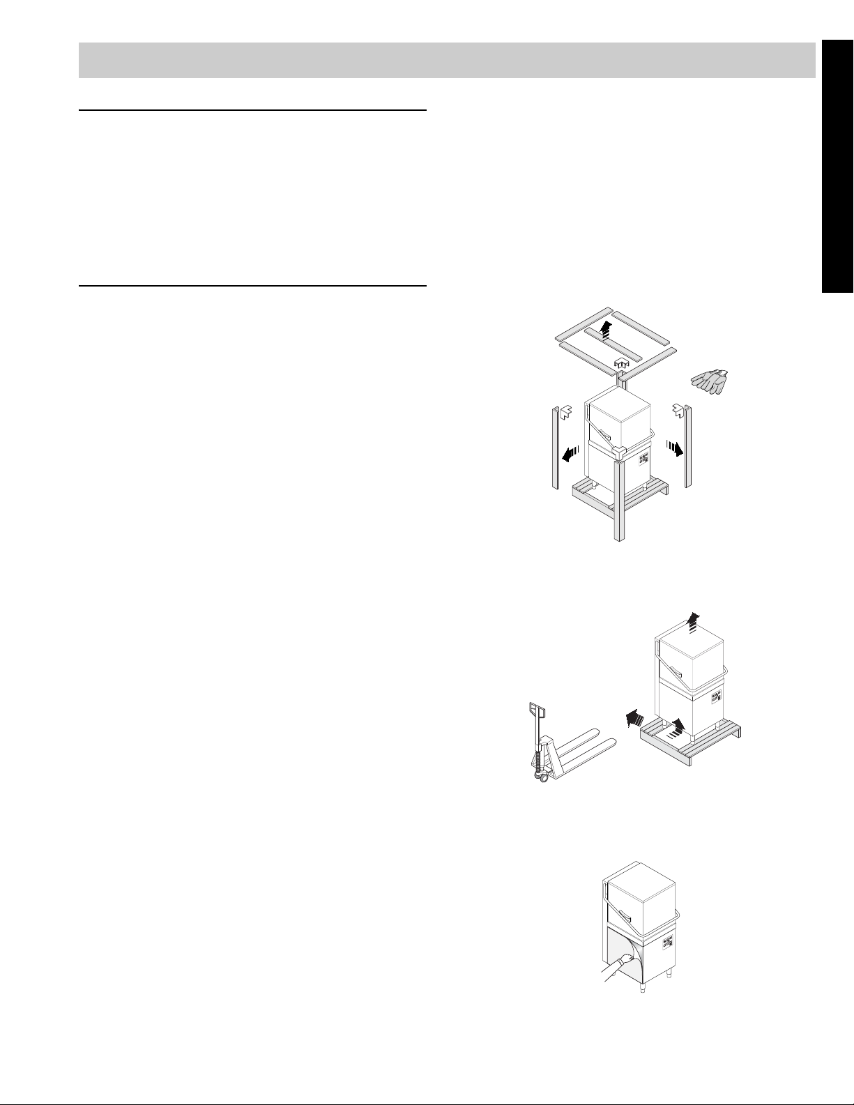
B1 HANDLING
Use suitable means to move the appliance: a lift truck or
fork pallet trucks (the forks should reach more than halfway beneath the appliance).
B2 UNPACKING
Wear protective gloves to unpack.
Lift the appliance using a lift truck,
Figure 1
NOTICE FOR SHIPPING DAMAGE
• The container should be examined for damage
before and during unloading.
• The freight carrier has assumed responsibility for its
safe transit and delivery.
• If damaged equipment is received, either apparent or
concealed, a claim must be made with the delivering
carrier. Apparent damage or loss must be noted on
the freight bill at the time of delivery.
• The freight bill must then be signed by the carrier
representative (Driver). If the bill is not signed, the
carrier may refuse the claim. The supply can supply
the necessary forms.
• A request for inspection must be made to the carrier
within 15 days if there is concealed damage or loss
that is not apparent until after the equipment is uncrated. The carrier should arrange an inspection.
• Be certain to hold all contents plus all packing material. Under no circumstances should a damaged
3
2
1
Figure 2
remove the base and position the appliance where it is
to be installed.
Figure 3
5

Remove the protective film and ensure that the packag-
PE
PP
PS
ing material is disposed of correctly in compliance with
the regulations in force in the country where the product
is to be used.
B3 DISPOSAL OF PACKING MATERIAL
All the packaging materials are environmentally safe and
friendly. They maybe kept without fear or danger. They
may be recycled or burned in a special waste incineration plant. Recyclable plastic components are marked as
follows:
polyethylene external wrapping film,
instruction bag.
polypropylene
polystyrene
foam
top packaging panels,
straps.
protective surround ele-
ments.
Wood and cardboard components may be disposed of
according to local regulations in force. Appliances that
have reached the end of their service life should be suitably disposed of. The appliance should be dismantled
according to regulations in force. All metal parts are in
stainless steel (AISI 304) and are removable. Plastic
parts are marked with the symbol of the material.
6
ENGLISH
B4 TECHNICAL DATA
MODEL WT65H WT65H
Supply voltage: 208 V, 1 ph, 60 Hz 39 amp 240 V, 1 ph, 60 Hz, 32 amp
Total Watts 13.6 kW 13.6 kW
Boiler heating elements 12.0 kW 12.0 kW
Tank heating elements 3.0 kW 3.0 kW
Water supply pressure 7.25 - 101 psi/50 - 700 kPa 7.25 - 101 psi/50 - 700k Pa
Water supply temperature 122°F/50°C 122°F/50°C
Water supply hardness for models without incorporated continuous water softner 140 ppm/14°fH max 140 ppm/14°fH max
Water supply hardness for models with incorporated continuous water softner 400 ppm/40°fH max 400 ppm/40°fH max
Rinse cycle water consumption 0,90 gallon/3.4 liters 0,90 gallon/3.4 liters
Boiler capacity 3 gallons/12 liters 3 gallons/12 liters
Tank capacity 11 gallons/42 liters 11 gallons/42 liters
Standard cycle time with water supply at 122°F/50°C 60/70/120 seconds 60/70/120 seconds
Legal noise level Leq <65 dB <65 dB
Minimum Supply - Circuit Ampacity 40 amp 33 amp
Net weight 282 lb/128 kg 282 lb/128 kg
Shipping weight 359.36 lb/163 kg 359.36 lb/163 kg
Shipping width 33 1/16” /840 mm 33 1/16” /840 mm
Shipping height 74 7/16” / 1890 mm 74 7/16” / 1890 mm
Shipping depth 36 5/8” / 930 mm 36 5/8” / 930 mm
Table 1
Standard cycle time may vary should the inlet water temperature be different from that indicated above.
WT65H208DU WT65H240DU WT65H208WS WT65H240WS
xx
7
25 7/16"
646 mm
26 5/16"
668 mm
59 3/8"
59 3/8"
1507 mm
1"
25 mm
10 3/8"
263 mm
21 7/16"
545 mm
9 5/16"
236 mm
6"
152 mm
32 1/8"
815 mm
26 5/16"
668 mm
29"
735 mm
SC
Y A
C
I
Q
4 7/16"
113 mm
13"
330 mm
8 5/8"
218 mm
1 1/2"
39 mm
C
I
22"
559 mm
2 7/8"
71 mm
6 5/8"
167 mm
4 7/8"
124 mm
2 5/16"
59 mm
2 5/16"
59 mm
15 3/8"
391 mm
A
7 7/8"
200 mm
34 1/2"
875 mm
76 13/16"
1953 mm
16 1/16"
409 mm
37"
940 mm
32 1/16"
815 mm
29 3/4"
756 mm
S YC
4 5/8"
118 mm
1507 mm
2 5/16"
59 mm
9 5/16"
236 mm
26 5/16"
1"
25 mm
21 7/16"
668 mm
25 7/16"
646 mm
545 mm
10 3/8"
263 mm
6"
152 mm
2 5/16"
59 mm
4 7/8"
124 mm
15 3/8"
391 mm
940 mm
32 1/16"
815 mm
29 3/4"
756 mm
22"
559 mm
37"
6 5/8"
167 mm
7 7/8"
200 mm
2 7/8"
71 mm
16 1/16"
409 mm
34 1/2"
875 mm
76 13/16"
1953 mm
13"
330 mm
8 5/8"
218 mm
1 1/2"
39 mm
32 1/8"
815 mm
4 5/8"
118 mm
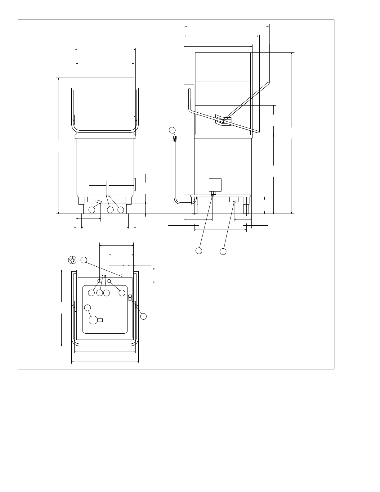
Legend Figure 4
A - Water inlet pipe with 3/4”dia/19mm fittings
26 5/16"
668 mm
29"
735 mm
C - Outlet pipe 1 5/8” ID /40 mm (^) –11/16” ID /18 mm (*).
I - Power supply
S - Detergent connection
Q - Equipotential (Ground) screw
Y - Rinse aid connection
(^) - Only for model with free-fall drainage
(*) - Only for model with drain pump
4 7/16"
113 mm
Figure 4
8
 Loading...