

Page 1

Milano
VISUAL DIVISION
graphic project
ELECTROLUX EUROCLEAN ITALIA SPA
Località Novella Terza 20070 Guardamiglio-Italy
Telephon nr. +39 377 451124 Fax nr. +39 377 51443
96 11-96
a
4
N
I
S31E34UK
W 345 B/M
W 355 B/M
W 365 B
W 375 B
MANUAL FOR USE
AND MAINTENANCE
Page 2
INDEX
NOTE
pag.
INTRODUCTION..................................................................1
UNPACKING ......................................................................2
TECHNICAL SPECIFICATION .................................................3
MACHINE CONTROLS .........................................................4
PREPARATION FOR USE ...................................................5-9
SCRUBBING AND DRYING OPERATION ........................10-15
CHANGING BRUSHES..................................................16-17
MAINTENANCE ...........................................................18-19
SAFETY AND FAULTS.........................................................20
TROUBLE SHOOTING ........................................................21
OPTIONALS.................................................................22-24
Page 3
A front splash guard is also available.
OPTIONALS
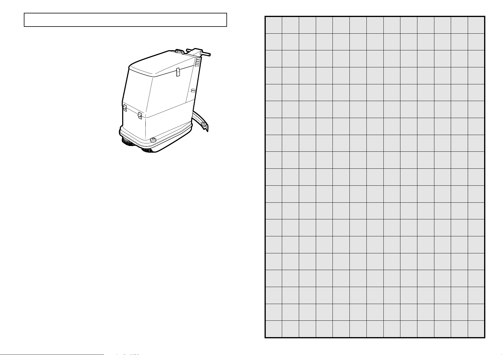
INTRODUCTION
INTRODUCTION
This manual is a guide to the efficient use of the machine and also contains practical information concerning the
functioning, adjustments and user maintenance of your new scrubber/drier. Your machine has been designed and
constructed to ensure maximum performarnce and ease of operation in a wide variety of applications. Before delivery, the
machine has been tested in our factory and by our distributor to ensure that it is delivered to you in perfect condition. To
maintain the machine in this condition and guarantee functioning without problems, it is essential that the periodic
maintenance operations indicated in this manual are properly carried out. Before using the machine, carefully read this
manual and keep it within easy reach for your future reference. Indications of “LEFT” and “RIGHT” are as seen from the
operators position. If you should need any further information concerning the machine, please do not hesitate to contact
either Electrolux Euroclean or our local distributor.
GENERAL SAFETY RULES
The rules below have to be followed carefully in order to
avoid damages to the operator and to the machine.
- Read the labels carefully on the machine; Do not cover
them for any reason and replace them immediately if
damaged.
- The socket for the power supply must be fitted with a
standard earthing (ground) system.
- With the brushes in working position, avoid touching or
passing over the mains cable. Avoid damaging by
squashing, bending or stressing.
- Where there is damage to the mains cable, stop the
machine, take off the plug from the mains system, and
replace the damaged cable immediately by calling the
Electrolux Service department.
- Do not mix different detergents, avoiding harmful odours.
- Do not place any liquid containers onto the machine.
- The storage temperature has to be between +15°C and +
55°C.
- The perfect operating temperature should be between 0°
C and 40° C.
- The humidity should be between 30 and 95%.
- Do not use the machine in explosive atmosphere.
- Do not use the machine as a means of transport.
- Do not use acid solutions which could damage the
machine.
- Avoid working with the brushes when the machine stands
still, in order to prevent floor damages.
- Do not vacuum iflammable liquids.
- In case of fire, use a powder extinguisher. Do not use
water.
- Do not strike shelvings or scaffoldings, where there is
danger of falling objects.
- Adapt the utilization speed to the adhesion conditions.
- Do not exceed over the limit gradient stated, to avoid
conditions of instability (2% max).
- The machine has to carry out simultaneously the
operations of washing and drying. Different operations
have to be carried out in areas which are not permitted
for the passage of non employed staff. Signal the areas
of moist floors with suitable signs.
- If the machine does not work properly, check by
conducting simple maintenance procedures. Otherwise,
it is better to ask for technical service.
-Where parts are required, ask for ORIGINAL spare parts
to an agent and/or to an authorized dealer.
- For any maintenance operation take off the power supply
from the machine.
- Do not take off the pieces which require the use of tools
to be removed.
- Do not wash the machine with direct water jets or with
high water pressure not with corrosive material.
- Every 200 working hours have a machine check through
a service department.
- The machine should not be abandoned, because of the
presence of toxic-harmful materials (batteries, oil etc.).
This disposal must be subject to the rules which provide
for its scrapping in appropiate centres.
- The machine does not cause any harmful vibrations.
24
MODIFICATIONS AND IMPROVEMENTS
Electrolux Euroclean aim toward continuous improvement of its machines and reserves the right to carry out modifications
and improvements whenever necessary without being obliged to update machines which have been sold previously.
SAFETY
You too can avoid accidents.
No accident prevention programme is effective without the total co-operation of the person directly responsible for the
functioning of the machine. The majority of accidents which may occur either during work or transferring the machine from
site to site are caused by the non-observance of the most elementary safety rules. An alert and cautious operator is the best
guarantee against accidents and is more effective than any other part of an accident prevention programme.
The machine must be switched off and disconnected from either its battery or mains supply before any servicing or
adjustment of operational parts are carried out. Ensure that any assistant is clear of the machine and that covers are closed
before switching on.
1
Page 4
1
2
3
4
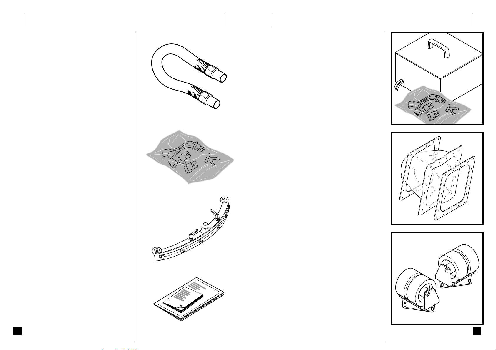
UNPACKING OPTIONALS
Check that you have received following parts
together with the machine:
- Connecting hose for squeegee
- Plastic bag with cables
Kit of cable to transform machine from mains
version to battery operated version.
Mains unit (or transformer) to change the machine
from the battery operated version to the mains
version.
For the models W345 and W355 a kit is
available to equip the machine with the
membrane.
- Squeegee
- Documents
2
In order to reduce the pressure of the machine on
the floor (according to norm DIN 18032) two rear
twin wheels can be mounted.
W345 and W355 cod. D00.06630
W365 and W375
cod. D00.06640
23
Page 5
O)
OPTIONALS
In addition to the normal accessories supplied
with the machine the following optionals are
available:
Batteries:
- For models 345/355 two 12 V batteries 140
amp hours.
- For models 365/375 four 6V batteries 240
amp hours.
Battery chargers:
- For models 345/355/365/375 two different
battery chargers are available with different
specifications according to the country where
there will be used: a) 24 Volts 30 A 50 Hz
b) 24 Volts 30 A 60
Hz
Different types of brushes and pad holders are
available. For a complete list consult your nearest
dealer.
W345 430mm (17 “) 1 required
Union mix scrub brush cod.145 00 42-00
Polypropylene scrub brush cod.145 00 96-00
Silicon Carbide scrub brush cod.140 00 63-00
Pad holder cod.145 00 43-00
W355 280mm (11 “) 2 required
Union mix scrub brush cod.145 00 45-00
Polypropylene scrub brush cod.145 00 97-00
Silicon Carbide scrub brush cod.145 00 64-00
Pad holder cod.145 00 46-00
W365 320mm (12,5 “) 2 required
Union mix scrub brush cod.145 01 02-00
Polypropylene scrub brush cod.145 01 00-00
Silicon Carbide scrub brush cod.140 01 03-00
Pad holder cod.145 01 04-00
W375 370mm (14,5 “) 2 required
Union mix scrub brush cod.145 01 07-00
Polypropylene scrub brush cod.145 01 05-00
Silicon Carbide scrub brush cod.140 01 08-00
Pad holder cod.145 01 09-00
TECHNICAL SPECIFICATION
MODELS
Working width (mm)
Width of squeegee (mm)
N° of brushes
Brush/s diameter (mm)
Brush speed (rpm)
Brush motor (watts)
Brush pressure (Kg)
Clean liquid tank (ltr)
Recovery tank (ltr)
Vacuum motor type
Vacuum motor (watts)
Vacuum depression (mm/H
Run time hour meter
Battery condition indicator
Traction motor (watts)
Forward speed (Km/H)
Reverse speed (Km/H)
Drive wheel diameter (mm)
Castor wheel diameter (mm)
Operating voltage (volts)
Length (mm)
Width (mm)
Height (mm)
Weight without batteries (kg)
Weight with mains unit (kg)
Standard wet batteries
Capacity 20 at hr rate (Ah)
Charger - taper current
Low maintenance dry batteries
Capacity 5 at hr rate (Ah)
Charger - constant voltage
(*) with the membrane (optional)
2
TECHNICAL SPECIFICATION
W345B/M
430 538 628 728
700 800 920 1010
1222
430 280 320 370
180 270 270 180
1x250 2x200 2x200 2x375
13-27 20-31 21-36 30-45
34/50 (*) 38/54 (*) 72 72
35/51 (*) 39/55 (*) 74 74
2 stages. 3 stages. 3 stages. 3 stages.
420 540 540 540
1150 1700 1700 1700
yes yes yes yes
yes yes yes yes
120 120 200 200
0-4,5 0-4,5 0-5 0-5
0-2,5 0-2,5 0-2,5 0-2,5
150 150 200 200
80 80 100 100
24 24 24 24
1235 1235 1330 1330
460 580 685 775
1050 1050 1095 1095
97 112 125 135
132 146 n/a n/a
2 x12v 2 x12v 4 x 6v 4 x 6v
140 140 240 240
12 cells 25 A 12 cells 25 A 12 cells 25 A 12 cells 25 A
2 x 12v 2 x 12v 4 x 6v 4 x 6v
70 70 160 160
24v. 25 A 24v. 25 A 24v. 25 A 24v. 25 A
W355B/M W365B W375B
22
3
Page 6

1
2
3
4
5
6
7
8
9
10
11
12
13
14
15
16
17
18
19
20
21
MACHINE CONTROLS
1324
56 7 8 9
- Scrubbing detergent flow adjustment
push button
- Suction on/off push button
- Brush motor on/off push button
- Run-time hour meter
- Scrubbing detergent flow boost pump
on/off push button
- Recovery tank full warning indicator
- Brush release push button
- Battery condition voltmeter
- Master key-switch
- Drive function control
- Switch for the speed selection
- Scrubbing detergent tank emptying
hose
- Handle height adjustment locking handwheel
- Drive motor on/off switch
- Squeegee control lever
- Recovery tank emptying hose
- Squeegee
- Brush pressure control hand-wheel
- Squeegee pressure control
- Squeegee rake angle control
- Brush lift/lower pedal
10
11
12
13
14
15
16
17
18
19
20
21
TROUBLE SHOOTING
PROBLEM POSSIBLE CAUSE CHECK
Nothing works.
No liquid supply to the
brushes.
Squeegee is not drying the
floor well.
All indicators flashing when
key switched on.
All 3 indicators of the battery
condition meter flashing.
3 indicators of battery
condition meter flashing in
sequence
No power.
Is the tank empty.
Are the brushes revolving and
the machine moving as well
as the flow control activated.
Is the tank filter blocked.
Are the solenoid valves
blocked.
Are the pipes blocked.
Blockage in hose.
Worn sgueegee not sitting
fully on floor.
Torn tank lid gasket.
Traction control not in neutral
position.
Traction drive electronics
faulty.
Overload in electrical circuit. Will reset when cooled
Is the battery plugged in.
Is the mains lead plugged in
and switched on.
Is the mains socket live.
Fill the tank.
Try this sequence.
Remove and clean.
Remove and clean.
Flush through with clean hot
water.
Remove and flush through
with water.
Adjust pressure and rake.
Replace
Centre the traction control
then switch the key on.
Call Service Engineer. or
Replace P.C.B.
down. Check motor currents
for overload, or tight
bearings etc.
4
21
Page 7

SAFETY AND FAULTS
Keyswitch/accelerator sequence:
This safety feature prevents the machine from
moving if the machine is accidentally switched on
with either forward or reverse function engaged
(due to machine fault or an operator error).
When this happens the leds on display panel
begin flashing.
Mosfet short circuit:
This safety feature prevents the machine from
moving if the machine is switched on with the the
part of the electronic print card controlling drive
power is in short circuit (in this case the machine
would move immediately at full speed). This
condition is signalled by the 3 voltmeter leds
which start flashing.
Overheating of the electronic print card
cooling vents:
This protection device of the electronic print card
prevents damage to the card itself during
prolonged use of the machine when one of its
functions is overloaded. In this condition the
machine automatically cuts off all its functions
which are then only restored when temperature
returns to normal value. This condition is signalled
by the lighting up in sequence of the 3 voltmeter
leds.
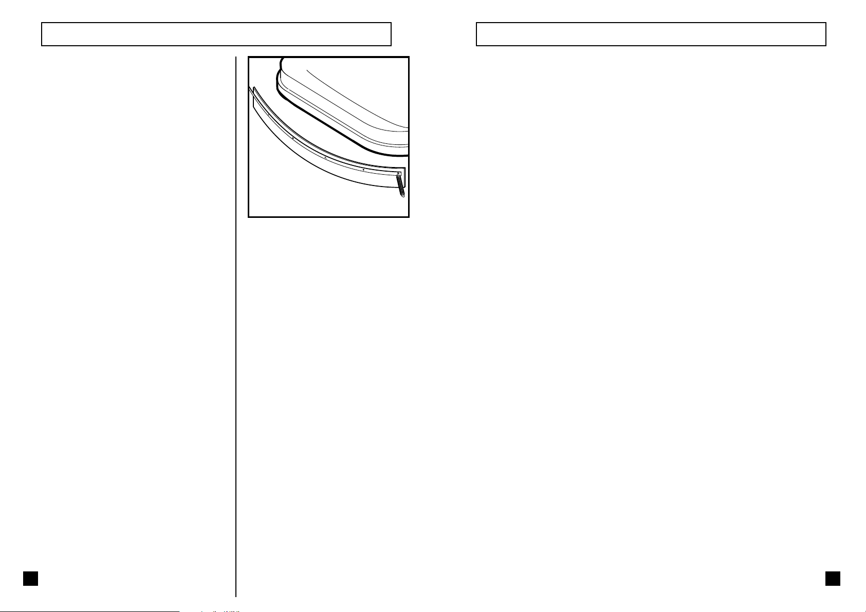
PREPARATION FOR USE
Partially unscrew the two middle levers on the
squeegee. Push the squeegee into the locating
lugs as illustrated and fully tighten the levers.
(pull the lever up to disingage it and make its
rotation free).
Push the coiled end of the squeegee hose fully
home onto the tubular spigot in the centre of the
squeegee.
Micro switch:
Micro switch to shut off all the functions when the
tank is in the upright position.
(SEMKO APPROVAL)
20
Push the straight end of the squeegee hose onto
the tank inlet pipe which protrudes through a slot
in the lower rear panel.
5
Page 8

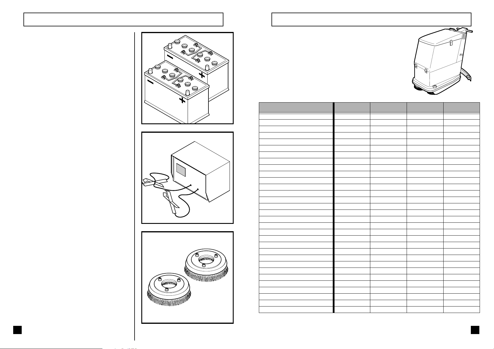
PREPARATION FOR USE
For models working with batteries follow
instructions below, whereas in the case of mains
operated models the transformer has already
been placed inside the machine and needs no
further installation.
The batteries are supplied without liquid,
therefore they must be filled up with the
appropriate acid before they can be used.
Take special care when handling the
acid as it is corrosive, If it should come
into contact with skin or eyes, wash
abundantly with water and consult a
doctor.
The W345B & W355B machines use two 12 volt
batteries, the W365B & W375B machines use
four 6 volt batteries.
Study the
illustrations then fit
the batteries and
connect the links
supplied as
indicated.
Plug the battery
socket into the
machine as shown.
Fold over the flaps
to cover the battery
tops, then lower the
tank unit to safely
cover exposed
working parts.
+
MAINTENANCE
The three solenoid valve bodies may be removed
by turning them through 45 degrees and lifting
them away to reveal the plunger and seating of
each valve. These should be cleaned of scale and
of any other foreign matter.
Regularly inspect the squeegee for damage or
wear to the lips. The lips may be easily replaced
by unscrewing the retaining strips, remove the
lips, replace with new, then screw the cover strips
back again to retain them.
-
Important:periodically clean the suction
filters; this is very important not to
+
reduce the suction capability of the
squeegee.
-
6
19
Page 9

MAINTENANCE
BEFORE ANY MAINTENANCE IS CARRIED
OUT THE BATTERY MUST BE UNPLUGGED
OR THE MAINS LEAD UNPLUGGED.
Periodically unscrew the filter inside the scrubbing
detergent tank, scrub whit a stiff brush under
running water to remove any accumulated foreign
matter.
Note: for the models 345-355 it is enough to pull
the filter to remove it. Press the filter to mount it.
For the battery operated models, the level of the
liquid inside batteries must be checked
periodically, and topped up with distilled water
if necessary.
Raise the bonnet, uncover the battery
compartment, remove caps and check level.
Special care should be taken
when handling battery liquid
as it is corrosive. If it should
come into contact with skin
or eyes, wash abundantly
with water and consult a
doctor.
365-375
345-355
PREPARATION FOR USE
The machine may now be run for trial purposes
but before putting it into service the batteries
should be charged to bring them up to their
maximum capacity.
New batteries will gradually “run in” and
increase in capacity to a maximum in about the
first 10 charge/discharge cycles.
-
+
If necessary the batteries should
be charged using an appropriate
battery charger. Remove the
battery caps during the charging
operation.
+
-
-
+
-
+
Recharge batteries when necessary with an
appropriate battery charger.
18
Check that the Hertz and Voltage
readings of the mains supply
correspond to those of the battery
charger.
7
Page 10

PREPARATION FOR USE
Drop the brushes (one or two depending on the
model) roughly side by side in front of the
machine, the actual position does not matter.
Switch the machine on by turning the key in the
key-switch a quarter turn clockwise. Wait
momentarily until the battery condition indicator
above the switch lights.
Note :
The mains machine will have to be plugged in,
the indicator then only shows that power is
available.
CHANGING BRUSHES
Position the new brushes roughly side by side on
the floor in front of the machine.
Move the machine forward until the brushes are
pushed along the floor. Release the brush lift/
lower pedal and allow it to settle at its highest
point. Rock the machine forward and back about
50mm (2”) to settle the drive plates into the brush
centers.
Drive the machine forward by holding the handgrips, then rolling the thumb wheels forward until
the machine moves completely over the brushes.
To stop release the thumb wheels and they will
return to a neutral position. This will ensure the
brushes are fully located under the drive plates.
8
Press the brush motor on/off push button to
engage the brushes. Press the brush pedal down
and latch it into its lower position, press the brush
push button again to stop the motors.
The machine is now ready for use again.
17
Page 11

CHANGING BRUSHES
To replace brushes carry out the following
sequence of operations:
The machine should be switched on but all
functions switched off.
Raise the brush unit by pressing down the brush
lift/lower pedal and latching in its lowest position.
Press the brush release push button momentarily
and the brushes at present fitted will be unloaded
from the machine.
PREPARATION FOR USE
Lower the brush unit by pushing the pedal to the
right to unlatch it. Then allow it to rise as far as it
will go. Push the machine forward then back
about 50mm (2”) to ensure the drive has located
in the brushes.
Press the brush “on/off” push button: the indicator
will light and the brush motors will engage the
brushes.
Move the machine backward by rolling the
traction control rearward until the brushes are
visible in front of the machine.
16
Once the brushes have locked on, raise the brush
unit by pushing the pedal down and latching it at
its lower position.
Press the brush “on/off” push button again (see
previous picture); the green indicator will wait for
the motors to spin down to stop before going out.
Note : The motors do not stop immediately.
The brushes are now loaded onto the machine.
9
Page 12

SCRUBBING AND DRYING OPERATION
Open the tank lid.
Fill the left tank with water to within about 75mm
(3”) from the top edge then add the scrubbing
detergent in a quantity to make a dilution
according to its instruction.
Too strong a mix wastes detergent, too weak a
mix will not work efficiently.
The machine is now ready for use so move off to
the site to be cleaned.
SCRUBBING AND DRYING OPERATION
Unclip the recovery tank emptying hose and
remove the drain plug whilst holding the pipe at
its highest extent, then lower it carefully into a
gully or drain.
Note:
It is against Water Regulations to discharge
detergents into a surface drain, only use a foul
gully or drain.
At the same time as emptying the recovery tank
check if the clean tank requires refilling.
If the clean liquid runs out then it is recommended
that to save time the recovery tank be emptied at
the same time as the clean tank is refilled.
Switch the machine on by turning the key in the
key-switch a quarter turn clockwise.
10
A switch is fitted on the rear panel to the right of
the control handle which controls the drive motor
power. With the switch lever in the up position the
traction motor is disconnected and the machine
may be pushed easily from site to site when the
mains lead is unplugged or when the batteries are
not available.
OFF
ON
15
Page 13

SCRUBBING AND DRYING OPERATION
Push the machine slowly forward, and adjust the
squeegee pressure control until the lips bend over
evenly as illustrated below. Then re-adjust the rake
control to make the radius of the squeegee sit
parallel to the floor and the lips bend evenly.
TRAVEL DIRECTION
FLOOR LEVEL
The lips must be replaced when they become
feather edged or torn.
Fully lift the squeegee control lever (just below and
to the right of the machine handle) to lower the
squeegee to a flat floor surface.
SCRUBBING AND DRYING OPERATION
Press the brush “on/off” push button: the indicator
will light and the brush motors will start.
Lower the brush unit by pushing the pedal to the
right to unlatch it.
If the recovery tank full indicator lights continuosly
for a period of 6 seconds the suction motor will
switch off and the tank will have to be emptied
before continuing the operation.
Note:
Lift the brushes whilst still moving forward then
stop traction, in that order, to avoid “polo rings”.
Lift the squeegee and stop the suction motor. Drive
the machine to an emptying point or use a transfer
trolly to empty the recovery tank.
14
Drive the machine forward by holding the handgrips. And turning the thumb wheels.
11
Page 14

SCRUBBING AND DRYING OPERATION
When the machine is ready for scrubbing select
the estimated amount of clean liquid required by
pressing the detergent flow control on/off push
button; an indicator will light which can be
increased in three steps for varying the quantity of
liquid delivered to the brushes.
If more liquid is required press the boost pump
on/off push button which will double the amount
of flow; this will be shown by the indicator.
Note:
The liquid will be delivered to the brushes only
when the machine is moving forward and the
brushes are rotating. If either the brushes or the
forward traction are stopped the liquid flow
will stop.
SCRUBBING AND DRYING OPERATION
Press the suction on/off push button.
Start the brushes rotating, move the machine
slowly forward, then immediately lower the
brushes to the floor by lifting the foot pedal. (If the
brushes are allowed to rotate in contact with the
floor without the machine moving then it is likely
to cause “polo rings” on the floor).
Whilst moving forward observe the cleaning
effect on the floor and adjust the detergent flow to
the minimum required whilst being liquid enough
to be picked up by the squeegee. This allows the
liquid to last longer before having to refill the
tank. If too little liquid is used the floor will dry
with a “sludgy” grey look to it.
The height of the drive handle can be adjusted by
turning the knob A.
The speed range can be selected by means of
switch B.
A
B
Lower the squeegee to the floor.
12
+
Adjust the brush pressure to the minimum
required; this will assist in using the least amount
of power necessary from the battery which will
then last longer before requiring recharge.
13
 Loading...