

Page 1

SERVICE MANUAL
W75 – W100 – W160 – W230
471 1553-51
Page 2

Page 3

NOTICE TO SERVICE PERSONNEL
INSTALLATION
Improper installation of Wascomat laundry and wet cleaning equipment can result in
personal injury and severe damage to the machine.
REFER INSTALLATION TO QUALIFIED PERSONNEL!
RISK OF ELECTRIC SHOCK
The equipment utilizes high Voltages. Disconnect electric power before servicing.
The use of proper service tools and techniques, and the use of proper repair procedures,
is essential to the safety of service personnel and equipment users.
REFER SERVICING TO QUALIFIED SERVICE PERSONNEL!
RISK OF PERSONAL INJURY
This equipment contains moving parts, and some components that may have sharp edges.
Improper or careless service procedures may result in serious injury to service personnel.
REFER SERVICING TO QUALIFIED SERVICE PERSONNEL!
ABOUT THIS MANUAL
This manual is intended to provide service guidance to qualified service personnel.
Wascomat and its authorized dealers make no determination regarding the qualification of
individuals requesting this service manual. The service provider assumes all risks inherent
to the servicing of this equipment and any risks that arise as result of the lack of
knowledge or ability of any person servicing this equipment.
REFER SERVICING TO QUALIFIED SERVICE PERSONNEL!
NOTE:
Improper installation or servicing of Wascomat equipment will void the
manufacturer's warranty!
Page 4
Machine description – Safety regulations
1
Summary
Service-
instruc-
tions
Data
Description of principle components
Programmes
Periodic maintenance
Function sequences – Fault finding
Automatic unit
Timer
Level control
Thermostat
2
3
4
5
11
12
21
22
23
24
25
26
27
Included
units and
components
Door and safety locking device
Motor
Inlet valve, water
Drain valve
Heating
Coin meter
Drum and bearings
28
29
30
31
32
33
34
35
36
37
38
39
40
41
42
Frame
43
44
45
46
47
48
49
50
Page 5

Page 6
Service
Manual
Fig.
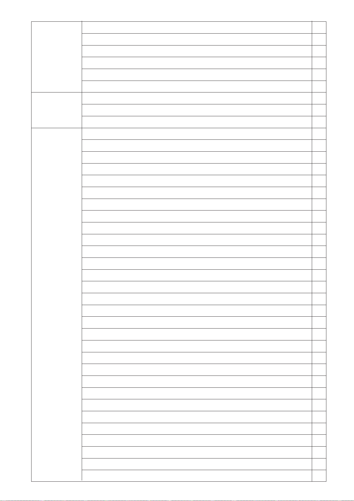
The 70 100, 160 and 230 litre washing machines described in this manual
1
are normal spin machines and differ only in size and washing capacity. The
machines are intended for installation in apartment houses, hotels,
laundries, industries, hospitals, smaller institutions and other regular users
who require machines with high reliability, large washing capacity and easy
maintenance.
Because the machines have a washing drum which is solidly mounted in
the frame, they require secure anchoring to the foundation.
The spin speed provides a G-factor of about 80.
The machines are supplied equipped in accordance with customer
specifications for electric, steam, gas heating or non-heating and can be
connected to various combinations of cold, hot and/or cold hard water.
The machines can be supplied with or without coin meter.
The machines are available with two different types of timer:
• Mechanical timer with fixed wash programs. The machine has switches
to select different standard programs.
1. Machine description
9112
91
Type
Edition
Page
1
• Electronic timer with fixed wash programs. The machine has switches to
select different standard programs. The timer also has a built-in troubleshooting program which increases possibilities for rational service.
1
1418
Page 7

1
EditionType
Page
1. Machine description
9112
92
Safety Regulations
• The machine is designed for water washing only.
• The machine must not be used by children.
• Installation and service work may only be carried out by qualified personnel.
• The machine’s door lock may not be bypassed under any circumstances.
• System leakage, such as a worn door gasket, should be repaired
immediately.
• Qualified personnel should study the relevant handbooks and service
manuals before any repairs or service are done.
• This machine may not be sprayed with water.
Service
Manual
Page 8

Service
Manual
2. Data
81
Type
9112
Edition
2
Page
W 75 W 100 W 160 W230
Dry weight capacity
at filling factor 1:13 5.4 kg 7.7 kg 12.3 kg 17.7 kg
at filling factor 1:10 7 kg 10 kg 16 kg 23 kg
Drum volume 70 lit 100 lit 160 lit 230 lit
diameter 520 mm 520 mm 620 mm 700 mm
depth 356 mm 473 mm 520 mm 600 mm
Drum speed wash 52 r/m 52 r/m 52 r/m 45 r/m
spin 530 r/m 530 r/m 500 r/m 455 r/m
G-factor wash 0.8 0.8 0.9 0.8
spin 81 81 87 81
Dimensions width 660 mm 660 mm 745 mm 825 mm
depth 649 mm 766 mm 995 mm 1090 mm
height 1050 mm 1050 mm 1195 mm 1320 mm
Recommended service space
side 250 mm 250 mm 250 mm 250 mm
rear 500 mm 500 mm 500 mm 500 mm
Min. space for moving
machine during servicing
side 50 mm 50 mm 50 mm 50 mm
rear 250 mm 250 mm 250 mm 250 mm
Weight net 107 kg 147 kg 202 kg 265 kg
gross, crate packed 117 kg 158 kg 220 kg 287 kg
gross, box packed 144 kg 185 kg 280 kg 352 kg
Transport volume
crate packed 0.62 m
box packed 0.77 m
3
3
0.65 m
0.8 m
3
3
1.1 m
1.5 m
3
3
1.42 m
1.8 m
3
3
Max floor load during spin 1.2±2.6 kN 1.7±3.4 kN 2.4±4.8 kN 3.1±5.2 kN
Frequency (dynamic load) 9 Hz 9 Hz 8.5 Hz 8.5 Hz
Water valves connection DN20 3/4 DN20 3/4" DN20 3/4'' DN20 3/4''
rec. water pressure 200-600 kPa 200-600 kPa 200-600 kPa 200-600 kPa
pressure limits 40-1000 kPa 40-1000 kPa 40-1000 kPa 40-1000 kPa
capacity at 300 kPa 27 l/min 27 l/min 27 l/min 100 l/min
Drain valve conn. outside diameter 75 mm 75 mm 75 mm 75 mm
capacity 160 l/min 160 l/min 160 l/min 160 l/min
Steam valve connection DN15 1/2" DN15 1/2" DN15 1/2'' DN15 1/2''
rec. steam pressure
300-600
Page 9

2
EditionType
Page
2. Data
9112
82
70 LITERS
Heating Voltage Total Fuse Cable crossalternative alternative kW A section mm
No heating 100 V 1 AC 50 Hz 1,4 20 3 x 4
or 100 V 1 AC 60 Hz 1,3 20 3 x 4
Steam heating 120 V 1 AC 60 Hz 1,2 16 3 x 2,5
200 V 3 AC 50 Hz 1,1 10 4 x 1,5
208-240 V 3 AC 60 Hz 1,1 10 4 x 1,5
220-230 V 1 AC 50 Hz 1,4 16 3 x 2,5
220-230 V 3 AC 50 Hz 1,2 10 4 x 1,5
240 V 1 AC 50 Hz 1,4 16 3 x 2,5
380-400 V 3N AC 50 HZ 1,2 10 5 x 1,5
415-440 V 3N AC 50 Hz 1,2 10 5 x 1,5
El 3,0 kW 220-240 V 1 AC 50 Hz 3,5 20 3 x 4
Service
Manual
2
380-400 V 3N AC 50 Hz 3.5 10 5 x 1,5
El 5,4 kW 220-230 V 1 AC 50 Hz 5,8 35 3 x 10
220-230 V 3 AC 50 Hz 5,8 16 4 x 2,5
240 V 1 AC 50 Hz 5,8 35 3 x 10
380-400 V 3N AC 50 Hz 5,8 10 5 x 1,5
415-440 V 3N AC 50 Hz 5,8 10 5 x 1,5
El 6,0 kW 380-415 V 3N AC 50 Hz 6,5 16 5 x 2,5
El 7,5 kW 220-230 V 3 AC 50 Hz 8,0 25 4 x 6
220-230 V 3 AC 60 Hz 8,0 25 4 x 6
240 V 3 AC 60 Hz 8,0 25 4 x 6
380-400 V 3 AC 50 Hz 8,0 16 4 x 2,5
380-400 V 3N AC 50 Hz 8,0 16 5 x 2,5
415-440 V 3 AC 50 Hz 8,0 16 4 x 2,5
415-440 V 3N AC 50 Hz 8,0 16 5 x 2,5
Page 10

Service
Manual
100 LITERS
Heating Voltage Total Fuse Cable crossalternative alternative kW A section mm
No heating 220 V 3 AC 50 Hz 1,6 10 4 x 1,5
or 415-440 V 3 AC 60 Hz 1,6 10 4 x 1,5
Steam heating 380-440 V 3N AC 50 Hz 1,6 10 5 x 1,5
415-440 V 3N AC 50 Hz 1,6 10 5 x 1,5
208-240 V 3 AC 60 Hz 1,6 10 4 x 1,5
120 V 1 AC 60 Hz 1,1 20 3 x 4
220-240 V 1 AC 50 Hz 1,7 16 3 x 2,5
El 7,5 kW 220-230 V 3 AC 50 Hz 8,1 25 4 x 6
380-400 V 3N AC 50 Hz 8,1 16 5 x 25
El 9 kW 415-440 V 3N AC 50 Hz 9,6 16 5 x 2,5
380-400 V 3 NAC 50 Hz 9,6 16 5 x 2,5
2. Data
83
9112
Type
Edition
2
Page
2
160 LITERS
Heating Voltage Total Fuse Cable crossalternative alternative kW A section mm
No heating 208-240 V 1 AC 60 Hz 2,6 16 3 x 2,5
or 208-240 V 3 AC 60 Hz 2,6 10 4 x 1,5
Steam heating 220-230 V 3 AC 50 Hz 2,6 10 4 x 1,5
380-440 V 3N AC 50 Hz 2,6 10 5 x 1,5
415-440 V 3N AC 50 Hz 2,6 10 5 x 1,5
El 12,0 kW 220-230 V 3 AC 50 Hz 12,8 35 4 x 10
380-400 V 3N AC 50 Hz 12,8 20 5 x 4
415-440 V 3N AC 50 Hz 12,8 20 5 x 4
230 LITERS
Heating Voltage Total Fuse Cable crossalternative alternative kW A section mm
No heating 208-240 V 3 AV 60 Hz 2,3 10 4 x 1,5
or 220-230 V 3 AC 50 Hz 2,3 10 4 x 1,5
2
2
Steam heating 380-400 V 3N AC 50 Hz 2,3 10 5 x 1,5
415-440 V 3N AC 50 Hz 2,3 10 5 x 1,5
El 18 kW 208-240 V 3 AC 60 Hz 18,9 50 4 x 16
220-230 V 3 AC 50 Hz 18,9 50 4 x 16
380-400 V 3N AC 50 Hz 18,9 35 5 x 10
415-440 V 3N AC 50 Hz 18,9 35 5 x 10
Page 11

Page 12
Service
Manual
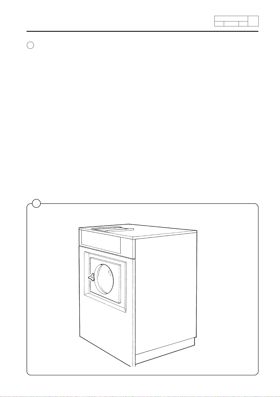
Fig.
The inner drum drive shaft is mounted in the outer drum with two ball
1
bearings at the back plate. Two neoprene gaskets make the shaft leak
resistant.
The motor is mounted on a rubber-cushioned shaft under the drum.
To prevent transmission of troublesome noises from chassis to the building
frame, the motor’s belt-tensioning device is also rubber-cushioned.
The drain valve is a membrane valve controlled with the help of the water
pressure in the cold water connection.
The door is electrically locked when the machine in running.
Timer, level control, thermostat, motor relays, etc., are located in the
automatic control unit which is easily accessible from the top of the
machine.
The front plate is available in a selection of finishes (galvanised/ painted or
in stainless steel). The side plates are galvanised/ painted, the rear panel is
galvanised/unpainted and the top panel is stainless steel.
5
3. Description of principle components
11 9020 1
9112
Type
Edition
Page
3
1
Detergent compartment
Control panel
Door and Safety lock
Inner drum
Drain valve
Inlet valve, water
Automatic control unit
Outer drum
Chassis
Motor
G119
Page 13
Service
Manual
4. Programmes
Identification of wash programs
The wash programs are identified by a combined letter and number symbol.
Identification occurs as described in the example below.
User catagory
10 19002
Edition
Type
Page
4
P = Standard
H = Hygienic and hospital.
These programs follow national
regulations
S = Selecta program. Special OPL-
program.
M = Mop program.
Timer type
E = electronic microprocessor-
controlled timer.
Electromechanical timer do not
have a letter positioned here in
the program name.
Example:
PE11CHd = electronic timer
P11CHd = electromechanical
timer
PE11CHd
Market
0 = Export
1 = Sweden
Machine family
1 = Machine with heating
2 = Machine for laundrettes, Europe
3 = Machine for laundrettes, USA and
4 = Machine for laundrettes,
5 = Machine for OPL, USA
6 = Machine for OPL, Selecta USA
Water connection
C = cold water
CH = cold and hot water
CHd = cold and cold hard water
CHHd = cold, hot and cold hard
water
and Asia
Canada
Denmark and West Germany
8 = Machine for laundrettes, Japan
The symbol PE11CHd used in the example above means:
• for standard user
• with electronic timer
• adapted for Sweden
• equipped with heating
• cold and cold hard water connection.
Page 14

10 2
9002
4
Type
PageEdition
4. Programmes
Program description
The wash programs identified by the symbol P11C are described on the
following pages. They are the programs designed for a regular user using a
heated machine with mechanical timer and intended for cold water
connection only.
These machines have eight fixed programs, which are selected by using the
knob on the control panel.
Program Wash type
Normal 95° white wash
Normal 60° colour wash
Normal 40° colour wash
Mild 30° delicate wash
Wool separate wool garments
Permanent press 40° fine wash
Service
Manual
Permanent press 60° coloured
Permanent press 95° white
By pushing the selector button HEAVILY SOILED a prewash and rinse will
be added to the three standard programs.
During cool-down, water filling and heating, the timer does not move. This
time is not included in the stated program times.
Page 15
Service
Manual
Program P11C
12 34 5 6 78
STANDARD STANDARD STANDARD STANDARD STANDARD STANDARD STANDARD STANDARD
NORMAL 95° NORMAL 60° NORMAL 40° DELICATE 30° WOOL PERM. PRESS 40° PERM. PRESS 60° PERM. PRESS 95°
ACTION
DETERGENT
LEVEL
TEMP
INLET WATER
TIME
ACTION
DETERGENT
LEVEL
TEMP
INLET WATER
TIME
ACTION
DETERGENT
LEVEL
TEMP
INLET WATER
TIME
ACTION
DETERGENT
LEVEL
TEMP
INLET WATER
TIME
ACTION
DETERGENT
LEVEL
TEMP
INLET WATER
TIME
ACTION
DETERGENT
LEVEL
TEMP
INLET WATER
TIME
ACTION
DETERGENT
LEVEL
TEMP
INLET WATER
TIME
ACTION
DETERGENT
LEVEL
TEMP
INLET WATER
TIME
3C-LL2N
3C-LL2N
3C-LL2N
3C-HL2G
3C-HL2G
3C-LL2N
3C-LL2N
3C-LL2N
C56
12 C 90 LL 2 N
C56
12 C 60 LL 2 N
---
12 C 40 LL 2 N
---
2C40HL-G
---
2C30HL-G
---
12 C 40 LL 2 N
C56
12 C 60 LL 2 N
C56
12 C 90 LL 2 N
4. Programmes
1N
1N
1N
1-
1-
1N
1N
1N
1C-HL-N
1N
2C-HL-N
1N
2C-HL3N
1N
0.5 E
1C-HL-N
1N
2C-HL-N
1N
0.5 E
1C-HL-N
1N
2C-HL-N
1N
0.5 E
--
1C-HL-G
1-
2C-HL-G
1-
--
1C-HL-G
1-
2C-HL-G
1-
1C-HL-N
1N
2C-HL-N
1N
0.5 E
1C-HL-N
1N
2C-HL-N
1N
0.5 E
1C-HL-N
1N
2C-HL-N
1N
0.5 E
1E
0.5 E
2C-HL3N
1N
1E
0.5 E
2C-HL3N
1N
1E
0.5 E
--
2C-HL3G
1G
1E
--
2C-HL3G
1G
1E
2C-HL3N
1N
0.5 E
0.5 E
0.5 E
1E
2C-HL3N
1N
1E
2C-HL3N
1N
1E
1.5 N
1.5 N
1.5 N
1.5
1.5 -
1.5 N
1.5 N
1.5 N
27.5 27.5 27.5 16.5 16.5 27.5 27.5 27.5
10 9002 3
Type
Edition
E = EXTRACTION
D = DISTRIBUTION
N = NORMAL ACTION 12/3 SEC
G = GENTLE ACTION 3/12 SEC
Page
4
PROGRAM
WITHOUT PRE WASH
PROGRAM
MAIN WASH
SEQUENCE
COOL DOWN
DRAIN
RINSE 1
DRAIN
EXTRACTION
RINSE 2
DRAIN
EXTRACTION
RINSE 3
DRAIN
EXTRACTION
RINSE 4
DRAIN
EXTRACTION
TOTAL TIME
SHAKE OUT
C = COLD WATER
LL = LOW LEVEL
HL = HIGH LEVEL
Page 16
10 9002 4
4
Type
Edition
Page
4. Programmes
Program P11C with prewash
ACTION
DETERGENT
LEVEL
TEMP
910111213141516
NORMAL 95° NORMAL 60° NORMAL 40° DELICATE 30° WOOL PERM. PRESS 40° PERM. PRESS 60° PERM. PRESS 95°
HEAVY SOILED HEAVY SOILED HEAVY SOILED
INLET WATER
TIME
ACTION
DETERGENT
LEVEL
TEMP
INLET WATER
TIME
ACTION
DETERGENT
LEVEL
TEMP
INLET WATER
TIME
ACTION
DETERGENT
LEVEL
TEMP
INLET WATER
TIME
ACTION
DETERGENT
LEVEL
TEMP
INLET WATER
TIME
ACTION
DETERGENT
LEVEL
TEMP
INLET WATER
TIME
6C-LL1N
0.5 N
ACTION
DETERGENT
LEVEL
TEMP
INLET WATER
TIME
6C-LL1N
0.5 N
ACTION
DETERGENT
LEVEL
TEMP
INLET WATER
TIME
6C-LL1N
0.5 N
3C-LL2N
3C-LL2N
3C-LL2N
3C-HL2G
3C-HL2G
C56
12 C 90 LL 2 N
C56
12 C 60 LL 2 N
---
12 C 40 LL 2 N
---
2C40HL-G
---
2C30HL-G
---
12 C 40 LL 2 N
C56
12 C 60 LL 2 N
C56
12 C 90 LL 2 N
1N
1N
1N
1-
1-
1N
1C-HL-N
1N
1C-HL-N
1N
1C-HL-N
1C-HL-N
1N
2C-HL-N
1N
2C-HL3N
1N
0.5 E
1C-HL-N
1N
0.5 E
1C-HL-N
1N
0.5 E
--
1C-HL-G
1-
--
1C-HL-G
1-
1N
1C-HL-N
1N
0.5 E
1N
1C-HL-N
1N
0.5 E
1N
1C-HL-N
1N
0.5 E
0.5 E
2C-HL-N
1N
0.5 E
2C-HL-N
1N
0.5 E
--
2C-HL-G
1-
--
2C-HL-G
1-
2C-HL-N
1N
0.5 E
2C-HL-N
1N
0.5 E
2C-HL-N
1N
0.5 E
1E
2C-HL3N
1N
1E
2C-HL3N
1N
1E
2C-HL3G
1G
1E
2C-HL3G
1G
1E
2C-HL3N
1N
1E
2C-HL3N
1N
1E
2C-HL3N
1N
1E
1.5 N
1.5 N
1.5 N
1.5
1.5
1.5 N
1.5 N
1.5 N
33 33 33 16.5 16.5 27.5 27.5 27.5
Service
Manual
E = EXTRACTION
D = DISTRIBUTION
N = NORMAL ACTION 12/3 SEC
G = GENTLE ACTION 3/12 SEC
PROGRAM
PROGRAM
SEQUENCE
PRE WASH
DRAIN
WITHOUT PRE WASH
MAIN WASH
COOL DOWN
DRAIN
RINSE
DRAIN
EXTRACTION
RINSE 2
DRAIN
EXTRACTION
RINSE 3
DRAIN
EXTRACTION
RINSE 4
DRAIN
EXTRACTION
SPIN DOWN
TOTAL TIME
C = COLD WATER
LL = LOW LEVEL
HL = HIGH LEVEL
Page 17
Service
Manual
4. Programmes
Identification of wash programs
The wash programs are identified by a combined letter and number symbol.
Identification occurs as described in the example below.
User catagory
P = Standard
H = Hygienic and hospital.
These programs follow national
regulations.
S = Selecta program. Special OPL-
program.
M = Mop program.
11 1
Type
9002
Edition
Page
4
Water connection
C = cold water
CH = cold and hot water
CHd = cold and cold hard water
CHHd = cold, hot and cold hard
water
PE11CHd
Timer type
E = electronic microprocessor-
controlled timer
Electromechanical timer do not
have a letter positioned here in
the program name.
Example:
PE11CHd = electronic timer
P11CHd = electromechanical
timer
The symbol PE11CHd used in the example above means:
Market
0 = Export
1 = Sweden
Machine family
1 = Machine with heating capacity
2 = Machine for laundrettes,
Europe and Asia
3 = Machine for laundrettes,
USA and Canada
4 = Machine for laundrettes,
Denmark and West Germany
5 = Machine for OPL, USA
6 = Machine for OPL, Selecta USA
8 = Machine for laundrettes, Japan
• for standard
• with electronic timer
• adapted for Sweden
• equipped with heating
• cold and cold hard water connection
Page 18
11 2
Type
4
9002
Service
PageEdition
4. Programmes
Manual
Program description
The wash programs identified by the sybol P11C
are described on the following pages. They are the
programs for a regular user in Sweden using a
heated machine with mechanical timer and
intended for cold water connection only. There are
more program variations available for machines
with electronic timer.
Machines with wash program PE11C have seven
fixed programs which are selected by pushing the
program buttons on the panel.
Program Wash type
Normal 95° white wash
Normal 60° colour wash
Normal 40° colour wash
Mild 30° delicate wash
Wool separate wool garments
Permanent press 40° fine wash
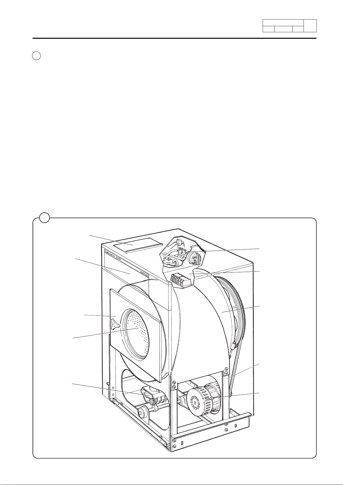
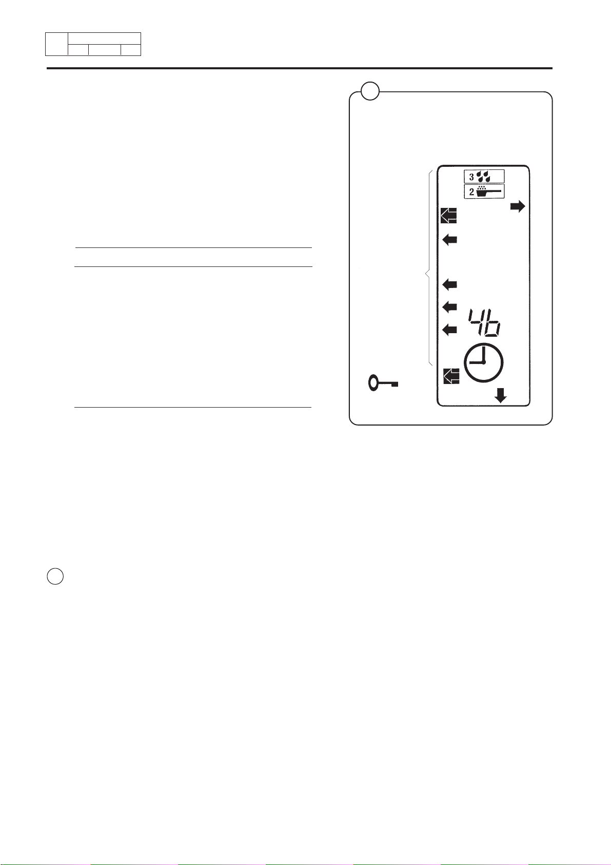
1
Nine arrow and
square
symbols
indicate
different
program steps
(shown here is
a program
example with
arrows 3, 4, 6,
7 and 8 in
use).
Permanent press 60° coloured
The programmer has two selector buttons,
HEAVILY SOILED and NO SPIN. By pushing in
one or the other or both simultaneously, a total of
28 different program variations are accessible.
During cool-down, water filling and heating, the
timer does not move. This program time is not
included in the stated program times.
Program indicator
Fig.
To the left in the display window, there are ten
1
arrow symbols which can be illuminated. A square
surrounding each arrow can also be illuminated.
The arrows light up when a program is selected in
order to indicate which program step is in progress.
During program operation, the squares around the
arrows light up when each program step is
completed.
In the following program schedule, there are
columns titled "PROG. INDIC." for each program.
The numbers included in the columns indicate
which squares should light. Squares which are
already illuminated remain lit throughout the
program operation.
1445
Page 19

Service
Manual
Program PE11C
12 3 4 5 6 7
STANDARD STANDARD STANDARD STANDARD STANDARD STANDARD STANDARD
NORMAL 95° NORMAL 60° NORMAL 40° DELICATE 30° WOOL PERM. PRESS 40° PERM. PRESS 60°
PROGIND
ACTION
DETERGENT
LEVEL
TEMP
INLET WATER
TIME
PROGIND
ACTION
DETERGENT
LEVEL
TEMP
INLET WATER
TIME
PROGIND
ACTION
DETERGENT
LEVEL
TEMP
INLET WATER
TIME
PROGIND
ACTION
DETERGENT
LEVEL
TEMP
INLET WATER
TIME
PROGIND
ACTION
DETERGENT
LEVEL
TEMP
INLET WATER
TIME
PROGIND
ACTION
DETERGENT
LEVEL
TEMP
INLET WATER
TIME
PROGIND
ACTION
DETERGENT
LEVEL
TEMP
INLET WATER
TIME
3C-LL2N3
3C-LL2N3
3C-HL2G3
3C-HL2G3
3C-LL2N3
3C-LL2N3
3C-LL2N3
4. Programmes
10 C 55 LL 2 N 3
10 C 40 LL 2 N 3
2C40HL2G3
2C30HL2G3
12 C 40 LL 2 N 3
12 C 55 LL 2 N 3
12 C 85 LL 2 N 3
0.5 N 4
0.5 N 4
0.5 4
0.5 4
0.5 N 4
0.5 N 4
CHLN4
0.5 N 4
1.5 C - LL - N 6
1.5 C - LL - N 6
1C-HL-G6
1C-HL-G6
1.5 C - LL - N 6
1.5 C - LL - N 6
1.5 C - LL - N 6
0.3 N 6
0.5 E 6
1.5 C - HL - N 7
0.3 N 6
0.5 E 6
1.5 C - HL - N 7
2C-HL-G7
0.5 6
2C-HL-G7
0.5 6
0.3 N 6
0.5 E 6
1.5 C - HL - N 7
0.3 N 6
0.5 E 6
1.5 C - HL - N 7
0.3 N 6
0.5 E 6
1.5 C - HL - N 7
11 9002 3
Type
Edition
2C-HL3N8
0.3 N 7
0.5 E 7
0.3 N 7
0.5 E 7
0.5 7
0.5 7
0.3 N 7
0.5 E 7
0.3 N 7
0.5 E 7
0.3 N 7
0.5 E 7
1E9
0.3 N 9
0.5 N 9
2C-HL3N8
1E9
0.3 N 9
0.5 N 9
2C-HL3G8
1E9
0.5 G 9
0.2 G 9
2C-HL3G8
1E9
0.5 G 9
0.2 G 9
2C-HL3N8
1E9
0.3 N 9
0.5 N 9
2C-HL3N8
1E9
0.3 N 9
0.5 N 9
2C-HL3N8
1E9
0.3 N 9
0.5 N 9
24 24 24 13.2 13.2 22 22
E = EXTRACTION
D = DISTRIBUTION
N = NORMAL ACTION 12/3 SEC
G = GENTLE ACTION 3/12 SEC
Page
4
PROGRAM
PROGRAM
SEQUENCE
PRE WASH
DRAIN
WITHOUT PRE WASH
MAIN WASH
COOL DOWN
DRAIN
RINSE 1
DRAIN
RINSE 2
DRAIN
EXTRACTION
RINSE 3
DRAIN
EXTRACTION
RINSE 4
DRAIN
SPIN DOWN
TOTAL TIME
EXTRACTION
C = COLD WATER
LL = LOW LEVEL
HL = HIGH LEVEL
Page 20
11 9002 4
4
Type
Edition
Page
4. Programmes
Program PE11C with "HEAVILY SOILED"
PROGIND
ACTION
DETERGENT
LEVEL
TEMP
8 9 10 11 12 13 14
NORMAL 95° NORMAL 60° NORMAL 40° DELICATE 30° WOOL PERM. PRESS 40° PERM. PRESS 60°
HEAVY SOILED HEAVY SOILED HEAVY SOILED STANDARD STANDARD HEAVY SOILED HEAVY SOILED
INLET WATER
TIME
PROGIND
ACTION
DETERGENT
LEVEL
TEMP
INLET WATER
TIME
PROGIND
ACTION
DETERGENT
LEVEL
TEMP
INLET WATER
TIME
PROGIND
ACTION
DETERGENT
LEVEL
TEMP
INLET WATER
TIME
PROGIND
ACTION
DETERGENT
LEVEL
TEMP
INLET WATER
TIME
6C-LL1N1
0.3 N 2
PROGIND
ACTION
DETERGENT
LEVEL
TEMP
INLET WATER
TIME
6C-LL1N1
0.3 N 2
PROGIND
ACTION
DETERGENT
LEVEL
TEMP
INLET WATER
TIME
6C-LL1N1
0.3 N 2
3C-LL2N3
12 C 60 LL 2 N 3
3C-LL2N3
12 C 40 LL 2 N 3
3C-HL2G3
2C40HL2G3
3C-HL2G3
2C30HL2G3
12 C 40 LL 2 N 3
12 C 60 LL 2 N 3
12 C 90 LL 2 N 3
C55 N 4
0.5 N 4
0.5 N 4
0.5 4
0.5 4
0.5 N 4
0.5 N 4
CHLN4
0.5 N 4
1.5 C - LL - N 6
0.3 N 6
0.5 E 6
1.5 C - HL - N 7
0.3 N 7
0.5 E 7
1.5 C - LL - N 6
0.3 N 6
0.5 E 6
1.5 C - HL - N 7
0.3 N 7
0.5 E 7
1C-HL-G6
1C-HL-G6
0.5 N 5
1.5 C - LL - N 6
1.5 C - LL - N 5
0.5 N 5
1.5 C - LL - N 6
1.5 C - LL - N 5
0.5 N 5
1.5 C - LL - N 6
1.5 C - LL - N 5
2C-HL-G7
0.5 6
0.5 6
0.3 N 6
0.3 N 6
0.3 N 6
0.5 7
2C-HL-G7
0.5 7
0.5 E 6
1.5 C - HL - N 7
0.3 N 7
0.5 E 7
0.5 E 6
1.5 C - HL - N 7
0.3 N 7
0.5 E 7
0.5 E 6
1.5 C - HL - N 7
0.3 N 7
0.5 E 7
2C-HL3N8
1E9
0.3 N 9
0.5 N 9
2C-HL3N8
1E9
0.3 N 9
0.5 N 9
2C-HL3G8
1E9
0.5 G 9
0.2 G 9
2C-HL3G8
1E9
0.5 G 9
0.2 G 9
2C-HL3N8
1E9
0.3 N 9
0.5 N 9
2C-HL3N8
1E9
0.3 N 9
0.5 N 9
2C-HL3N8
1E9
0.3 N 9
0.5 N 9
29.3 29.3 29.3 13.2 13.2 24 24
D = DISTRIBUTION
Service
Manual
E = EXTRACTION
N = NORMAL ACTION 12/3 SEC
G = GENTLE ACTION 3/12 SEC
PROGRAM
PROGRAM
SEQUENCE
PRE WASH
DRAIN
WITHOUT PRE WASH
MAIN WASH
COOL DOWN
DRAIN
RINSE 1
DRAIN
RINSE 2
DRAIN
EXTRACTION
RINSE 3
DRAIN
EXTRACTION
RINSE 4
DRAIN
TOTAL TIME
EXTRACTION
SPIN DOWN
C = COLD WATER
LL = LOW LEVEL
HL = HIGH LEVEL
Page 21

Service
Manual
4. Programmes
Program PE11C with "NO SPIN"
PROGIND
ACTION
DETERGENT
LEVEL
TEMP
INLET WATER
15 16 17 18 19 20 21
NORMAL 95° NORMAL 60° NORMAL 40° DELICATE 30° WOOL PERM. PRESS 40° PERM. PRESS 60°
NO EXTRACTION NO EXTRACTION NO EXTRACTION NO EXTRACTION NO EXTRACTION NO EXTRACTION NO EXTRACTION
TIME
PROGIND
ACTION
DETERGENT
LEVEL
TEMP
INLET WATER
TIME
PROGIND
ACTION
DETERGENT
LEVEL
TEMP
INLET WATER
TIME
PROGIND
ACTION
DETERGENT
LEVEL
TEMP
INLET WATER
TIME
PROGIND
ACTION
DETERGENT
LEVEL
TEMP
INLET WATER
TIME
PROGIND
ACTION
DETERGENT
LEVEL
TEMP
INLET WATER
TIME
PROGIND
ACTION
DETERGENT
LEVEL
TEMP
INLET WATER
TIME
3C-LL2N3
10 C 55 LL 2 N 3
3C-LL2N3
10 C 40 LL 2 N 3
3C-HL2G3
2C40HL2G3
3C-HL2G3
2C30HL2G3
3C-LL2N3
12 C 40 LL 2 N 3
3C-LL2N3
12 C 55 LL 2 N 3
3C-LL2N3
12 C 85 LL 2 N 3
0.5 N 4
0.5 N 4
0.5 4
0.5 4
0.5 N 4
0.5 N 4
CHLN4
0.5 N 4
1.5 C - LL - N 6
1.5 C - LL - N 6
1C-HL-G6
1C-HL-G6
1.5 C - LL - N 6
1.5 C - LL - N 6
1.5 C - LL - N 6
11 9002 5
Type
Edition
0.3 N 6
1.5 C - HL - N 7
0.3 N 6
1.5 C - HL - N 7
2C-HL-G7
0.5 6
2C-HL-G7
0.5 6
0.3 N 6
1.5 C - HL - N 7
0.3 N 6
1.5 C - HL - N 7
0.3 N 6
1.5 C - HL - N 7
2C-HL3N8
0.3 N 7
0.3 N 7
0.5 7
0.5 7
0.3 N 7
0.3 N 7
0.3 N 7
0.3 N 8
2C-HL3N8
0.3 N 8
2C-HL3G8
0.5 G 8
2C-HL3G8
0.5 G 8
2C-HL3N8
0.3 N 8
2C-HL3N8
0.3 N 8
2C-HL3N8
0.3 N 8
21.5 21.5 21.5 12 12 19.5 19.5
E = EXTRACTION
D = DISTRIBUTION
N = NORMAL ACTION 12/3 SEC
G = GENTLE ACTION 3/12 SEC
Page
4
PROGRAM
PROGRAM
SEQUENCE
PRE WASH
DRAIN
WITHOUT PRE WASH
MAIN WASH
COOL DOWN
DRAIN
RINSE 1
DRAIN
RINSE 2
DRAIN
EXTRACTION
RINSE 3
DRAIN
EXTRACTION
RINSE 4
DRAIN
EXTRACTION
TOTAL TIME
SPIN DOWN
C = COLD WATER
LL = LOW LEVEL
HL = HIGH LEVEL
Page 22

11 9002 6
4
Type
Edition
Page
4. Programmes
Program PE11C with "HEAVILY SOILED" and " NO SPIN"
PROGIND
ACTION
DETERGENT
LEVEL
TEMP
22 23 24 25 26 27 28
NORMAL 95° NORMAL 60° NORMAL 40° DELICATE 30° WOOL PERM. PRESS 40° PERM. PRESS 60°
H. SOIL + NO EXTR. H. SOIL + NO EXTR. H. SOIL + NO EXTR. H. SOIL + NO EXTR. H. SOIL + NO EXTR. H. SOIL + NO EXTR. H. SOIL + NO EXTR.
INLET WATER
TIME
PROGIND
ACTION
DETERGENT
LEVEL
TEMP
INLET WATER
TIME
PROGIND
ACTION
DETERGENT
LEVEL
TEMP
INLET WATER
TIME
PROGIND
ACTION
DETERGENT
LEVEL
TEMP
INLET WATER
TIME
PROGIND
ACTION
DETERGENT
LEVEL
TEMP
INLET WATER
TIME
6C-LL1N1
0.3 N 2
PROGIND
ACTION
DETERGENT
LEVEL
TEMP
INLET WATER
TIME
6C-LL1N1
0.3 N 2
PROGIND
ACTION
DETERGENT
LEVEL
TEMP
INLET WATER
TIME
6C-LL1N1
0.3 N 2
3C-LL2N3
12 C 60 LL 2 N 3
3C-LL2N3
12 C 40 LL 2 N 3
3C-HL2G3
2C40HL2G3
3C-HL2G3
2C30HL2G3
12 C 40 LL 2 N 3
12 C 60 LL 2 N 3
12 C 90 LL 2 N 3
C55 N 4
0.5 N 4
0.5 N 4
0.5 4
0.5 4
0.5 N 4
0.5 N 4
CHLN4
0.5 N 4
1.5 C - LL - N 6
0.3 N 6
1.5 C - HL - N 7
1.5 C - LL - N 6
0.3 N 6
1.5 C - HL - N 7
1C-HL-G6
1C-HL-G6
0.5 N 5
1.5 C - LL - N 6
1.5 C - LL - N 5
0.5 N 5
1.5 C - LL - N 6
1.5 C - LL - N 5
0.5 N 5
1.5 C - LL - N 6
1.5 C - LL - N 5
2C-HL-G7
0.5 6
2C-HL-G7
0.5 6
0.3 N 6
1.5 C - HL - N 7
0.3 N 6
1.5 C - HL - N 7
0.3 N 6
1.5 C - HL - N 7
2C-HL3N8
0.3 N 7
0.3 N 7
0.5 7
0.5 7
0.3 N 7
0.3 N 7
0.3 N 7
0.3 N 8
2C-HL3N8
0.3 N 8
2C-HL3G8
0.5 G 8
2C-HL3G8
0.5 G 8
2C-HL3N8
0.3 N 8
2C-HL3N8
0.3 N 8
2C-HL3N8
0.3 N 8
26.8 26.8 26.8 12 12 21.5 21.5
E = EXTRACTION
D = DISTRIBUTION
G = GENTLE ACTION 3/12 SEC
Service
Manual
N = NORMAL ACTION 12/3 SEC
PROGRAM
PRE WASH
PROGRAM
DRAIN
SEQUENCE
WITHOUT PRE WASH
MAIN WASH
COOL DOWN
DRAIN
RINSE 1
DRAIN
RINSE 2
DRAIN
EXTRACTION
RINSE 3
DRAIN
EXTRACTION
RINSE 4
DRAIN
SPIN DOWN
TOTAL TIME
EXTRACTION
C = COLD WATER
LL = LOW LEVEL
HL = HIGH LEVEL
Page 23

Service
Manual
4. Programmes
Identification of wash programs
The wash programs are identified by a combined letter and number symbol.
Identification occurs as described in the example below.
User catagory
9002
12 1
Type
Edition
Page
4
P= Standard
H= Hygienic and hospital.
These programs follow national
regulations.
S= Selecta program. Special OPL-
program.
M= Mop program.
Timer type
E= electronic microprocessorcontrolled timer
Electromechanical timer do not
have a letter positioned here in
the program name.
Example:
PE01CH = electronic
timer
P01CH = electromechanical
timer
PE01CH
Market
0= Export
1= Sweden
Machine family
1= Machine with heating
2= Machine for laundrettes, Europe
and Asia
3= Machine for laundrettes, USA
and Canada
4= Machine for laundrettes, Denmark
and West Germany
5= Machine for OPL, USA
6= Machine for OPL, Selecta USA
8= Machine for laundrettes, Japan
Water connection
C = cold water
CH = cold and hot water
CHd = cold and cold hard
water
CHHd = cold, hot and cold hard
water
The symbol PE01CH used in the example above means:
• for standard user
• with electronic timer
• equipped with heating
• cold and hot water connection
Page 24
12 9002 2
4
Type
Edition
Page
Program P01CH
12 34 5 6 78
STANDARD STANDARD STANDARD STANDARD STANDARD STANDARD STANDARD STANDARD
NORMAL 95° NORMAL 60° NORMAL 40° DELICATE 30° WOOL 40° PERM. PRESS 40° PERM. PRESS 60° PERM. PRESS 95°
ACTION
DETERGENT
LEVEL
TEMP
INLET WATER
TIME
ACTION
DETERGENT
LEVEL
TEMP
INLET WATER
TIME
ACTION
DETERGENT
LEVEL
TEMP
INLET WATER
TIME
ACTION
DETERGENT
LEVEL
TEMP
INLET WATER
TIME
ACTION
DETERGENT
LEVEL
TEMP
INLET WATER
TIME
ACTION
DETERGENT
LEVEL
TEMP
INLET WATER
TIME
ACTION
DETERGENT
LEVEL
TEMP
INLET WATER
TIME
ACTION
DETERGENT
LEVEL
TEMP
INLET WATER
TIME
3C-HL2G
3C-HL2G
4. Programmes
C56
1N
12 W 90 LL 2 N
C56
1N
12 W 60 LL 2 N
-1N
12 W 40 LL 2 N
--
2C40HL-G
1-
--
2C30HL-G
1-
-1N
12 W 40 LL 2 N
-1N
12 W 60 LL 2 N
-1N
12 W 90 LL 2 N
1C-HL-N
1N
2C-HL-N
0.5 E
1C-HL-N
1N
2C-HL-N
0.5 E
1C-HL-N
1N
2C-HL-N
1N
0.5 E
--
1C-HL-G
1-
2C-HL-G
1-
--
1C-HL-G
1-
2C-HL-G
1-
1C-HL-N
1N
2C-HL-N
1N
0.5 E
1C-HL-N
1N
2C-HL-N
1N
0.5 E
1C-HL-N
1N
2C-HL-N
1N
0.5 E
1N
2C-HL3N
1N
1E
0.5 E
1N
0.5 E
0.5 E
--
2C-HL3G
--
2C-HL3G
2C-HL3N
0.5 E
2C-HL3N
0.5 E
0.5 E
1.5 N
2C-HL3N
1N
1E
1.5 N
2C-HL3N
1N
1E
1.5 N
1G
1E
1.5 -
1G
1E
1.5 -
1N
4E
1.5 N
1N
4E
1.5 N
27.5 27.5 27.5 16.5 16.5 24.5 24.5 24.5
C = COLD WATER (15° C)
H = HOT WATER (65° C)
W = WARM WATER (35° C)
LL = LOW LEVEL
HL = HIGH LEVEL
2C-HL3N
1N
4E
1.5 N
Service
Manual
PROGRAM
PRE WASH
CYCLE
DRAIN
WITHOUT PRE WASH
MAIN WASH
COOL DOWN
DRAIN
RINSE 1
DRAIN
EXTRACTION
RINSE 2
DRAIN
EXTRACTION
RINSE 3
DRAIN
EXTRACTION
RINSE 4
DRAIN
EXTRACTION
SHAKE OUT
TOTAL TIME
- = NO ACTION
E = EXTRACTION
N = NORMAL ACTION
G = GENTLE ACTION
Page 25
Service
Manual
4. Programmes
Program P01CH with "HEAVY SOILED"
ACTION
DETERGENT
LEVEL
TEMP
910111213141516
NORMAL 95° NORMAL 60° NORMAL 40° DELICATE 30° WOOL 40° PERM. PRESS 40° PERM. PRESS 60° PERM. PRESS 95°
HEAVY SOILED HEAVY SOILED HEAVY SOILED
INLET WATER
TIME
ACTION
DETERGENT
LEVEL
TEMP
INLET WATER
TIME
ACTION
DETERGENT
LEVEL
TEMP
INLET WATER
TIME
ACTION
DETERGENT
LEVEL
TEMP
INLET WATER
TIME
ACTION
DETERGENT
LEVEL
TEMP
INLET WATER
TIME
ACTION
DETERGENT
LEVEL
TEMP
INLET WATER
TIME
6W-LL1N
ACTION
DETERGENT
LEVEL
TEMP
INLET WATER
TIME
6W-LL1N
ACTION
DETERGENT
LEVEL
TEMP
INLET WATER
TIME
6W-LL1N
C56
1N
12 W 90 LL 2 N
C56
1N
12 W 60 LL 2 N
-1N
12 W 40 LL 2 N
--
3C-HL2G
2C40HL-G
1-
--
3C-HL2G
2C30HL-G
1-
-1N
12 W 40 LL 2 N
0.5 N
-1N
12 H 60 LL 2 N
0.5 N
-1N
12 H 90 LL 2 N
0.5 N
1C-HL-N
1N
2C-HL-N
0.5 E
1C-HL-N
1N
2C-HL-N
0.5 E
1C-HL-N
1N
2C-HL-N
0.5 E
--
1C-HL-G
1-
2C-HL-G
--
1C-HL-G
1-
2C-HL-G
--
1C-HL-N
1
1C-HL-N
1N
2C-HL-N
0.5 E
--
1C-HL-N
1
1C-HL-N
1N
2C-HL-N
0.5 E
--
1C-HL-N
1
1C-HL-N
1N
2C-HL-N
0.5 E
12 9002 3
Type
1N
2C-HL3N
1N
1E
0.5 E
1N
0.5 E
1N
0.5 E
--
1-
--
1-
1N
0.5 E
1N
0.5 E
1N
0.5 E
1.5 N
2C-HL3N
1N
1E
1.5 N
2C-HL3N
1N
1E
1.5 N
2C-HL3G
1G
1E
1.5 -
2C-HL3G
1G
1E
1.5 -
2C-HL3N
1N
4E
1.5 N
2C-HL3N
1N
4E
1.5 N
36 36 36 16.5 16.5 24.5 24.5 24.5
C = COLD WATER (15° C)
H = HOT WATER (65° C)
W = WARM WATER (35° C)
LL = LOW LEVEL
HL = HIGH LEVEL
2C-HL3N
1N
4E
1.5 N
Edition
Page
4
PROGRAM
PRE WASH
CYCLE
DRAIN
WITHOUT PRE WASH
MAIN WASH
COOL DOWN
DRAIN
RINSE 1
DRAIN
EXTRACTION
RINSE 2
DRAIN
EXTRACTION
RINSE 3
DRAIN
EXTRACTION
RINSE 4
DRAIN
EXTRACTION
SHAKE OUT
TOTAL TIME
- = NO ACTION
E = EXTRACTION
N = NORMAL ACTION
G = GENTLE ACTION
Page 26

Service
Manual
4. Programmes
Identification of wash programs
The wash programs are identified by a combined letter and number symbol.
Identification occurs as described in the example below.
User catagory
9002
13 1
Type
Edition
Page
4
P= Standard
H= Hygienic and hospital.
These programs follow national
regulations.
S= Selecta program. Special OPL-
program.
M= Mop program.
Timer type
E= electronic microprocessorcontrolled timer
Electromechanical timer do not
have a letter positioned here in
the program name.
Example:
PE01CH = electronic
timer
P01CH = electromechanical
timer
PE01CH
Market
0= Export
1= Sweden
Machine family
1= Machine with heating
2= Machine for laundrettes, Europe
and Asia
3= Machine for laundrettes, USA
and Canada
4= Machine for laundrettes, Denmark
and West Germany
5= Machine for OPL, USA
6= Machine for OPL, Selecta USA
8= Machine for laundrettes, Japan
Water connection
C = cold water
CH = cold and hot water
CHd = cold and cold hard
water
CHHd = cold, hot and cold hard
water
The symbol PE01CH used in the example above means:
• for standard user
• with electronic timer
• equipped with heating
• cold and hot water connection
Page 27
13 9002 2
4
Type
Edition
Page
Program PE01CH
01 02 03 04 05 06 07
STANDARD STANDARD STANDARD STANDARD STANDARD STANDARD STANDARD
NORMAL 95° NORMAL 60° NORMAL 40° DELICATE 30° WOOL PERM. PRESS 40° PERM. PRESS 60°
PROGIND
ACTION
DETERGENT
LEVEL
TEMP
INLET WATER
TIME
PROGIND
ACTION
DETERGENT
LEVEL
TEMP
INLET WATER
TIME
PROGIND
ACTION
DETERGENT
LEVEL
TEMP
INLET WATER
TIME
PROGIND
ACTION
DETERGENT
LEVEL
TEMP
INLET WATER
TIME
PROGIND
ACTION
DETERGENT
LEVEL
TEMP
INLET WATER
TIME
PROGIND
ACTION
DETERGENT
LEVEL
TEMP
INLET WATER
TIME
PROGIND
ACTION
DETERGENT
LEVEL
TEMP
INLET WATER
TIME
3C-HL2G3
3C-HL2G3
4. Programmes
10 W 55 LL 2 N 3
0.5 N 4
10 W 40 LL 2 N 3
0.5 N 4
2C40HL2G3
0.5 - 4
2C30HL2G3
0.5 - 4
1N4
16 W 40 LL 4 N 3
1N4
14 W 55 LL 4 N 3
1N4
14 W 85 LL 4 N 3
1.5 C - LL - N 6
1.5 C - LL - N 6
1C-HL-G6
1C-HL-G6
1.5 C - LL - N 6
1.5 C - LL - N 6
1.5 C - LL - N 6
0.3 N 6
0.5 6
0.3 N 6
0.5 6
0.5 - 6
0.5 - 6
0.3 N 6
0.5 6
0.3 N 6
0.5 6
0.3 N 6
0.5 6
1.5 C - HL - N 7
1.5 C - HL - N 7
2C-HL-G7
1C-HL-G7
1.5 C - HL - N 7
1.5 C - HL - N 7
1.5 C - HL - N 7
Service
Manual
N
N
2C-HL3N8
0.3 N 7
0.5 7
0.3 N 7
0.5 7
0.5 - 7
0.5 - 7
0.3 N 7
0.5 7
0.3 N 7
0.5 7
0.3 N 7
0.5 7
19
0.3 N 9
0.5 N 9
N
N
2C-HL3N8
19
0.3 N 9
0.5 N 9
-
G
2C-HL3G8
19
0.5 G 9
0.2 G 9
-
G
2C-HL3G8
19
0.5 G 9
0.2 G 9
N
N
2C-HL3N8
69
0.3 N 9
0.5 N 9
N
N
2C-HL3N8
49
0.3 N 9
0.5 N 9
N
N
26.4 26.4 30.4 12.2 13.2 18.9 18.9
C = COLD WATER (15° C)
H = HOT WATER (65° C)
W = WARM WATER (35° C)
LL = LOW LEVEL
HL = HIGH LEVEL
2C-HL3N8
49
0.3 N 9
0.5 N 9
PROGRAM
PROGRAM
SEQUENCE
PRE WASH W 1
DRAIN
MAIN WASH W 1
MAIN WASH W 1
COOL DOWN
DRAIN
RINSE 1
DRAIN
EXTRACTION
RINSE 2
DRAIN
EXTRACTION
RINSE 3
DRAIN
EXTRACTION
RINSE 4
SHAKE OUT
DRAIN
EXTRACTION
FILLING
HEATING
- = NO ACTION
TOTAL TIME
E = EXTRACTION
N = NORMAL ACTION
G = GENTLE ACTION
Page 28
Service
Manual
4. Programmes
Program PE01CH with "HEAVY SOILED"
PROGIND
ACTION
DETERGENT
LEVEL
TEMP
08 09 10 11 12 13 14
NORMAL 95° NORMAL 60° NORMAL 40° DELICATE WOOL PERM. PRESS 40° PERM. PRESS 60°
HEAVY SOILED HEAVY SOILED HEAVY SOILED STANDARD STANDARD HEAVY SOILED HEAVY SOILED
INLET WATER
TIME
PROGIND
ACTION
DETERGENT
LEVEL
TEMP
INLET WATER
TIME
PROGIND
ACTION
DETERGENT
LEVEL
TEMP
INLET WATER
TIME
PROGIND
ACTION
DETERGENT
LEVEL
TEMP
INLET WATER
TIME
PROGIND
ACTION
DETERGENT
LEVEL
TEMP
INLET WATER
TIME
6 W 30 LL 1 N 1
0.5 N 2
PROGIND
ACTION
DETERGENT
LEVEL
TEMP
INLET WATER
TIME
6 W 30 LL 1 N 1
0.5 N 2
PROGIND
ACTION
DETERGENT
LEVEL
TEMP
INLET WATER
TIME
6 W 30 LL 1 N 1
0.5 N 2
3C-HL2G3
3C-HL2G3
C55 N 4
14 W 60 LL 2 N 3
0.5 N 4
1.5 C - LL - N 5
16 W 40 LL 2 N 3
0.5 N 4
1.5 C - LL - N 5
2C40HL2G3
0.5 - 4
2C30HL2G3
0.5 - 4
1N4
16 W 40 LL 4 N 3
1.5 C - LL - N 5
1N4
16 H 60 LL 4 N 3
1.5 C - LL - N 5
1N4
16 H 90 LL 4 N 3
1.5 C - LL - N 5
0.5 N 5
1.5 C - LL - N 6
0.3 N 6
0.5 6
1.5 C - HL - N 7
0.3 N 7
0.5 N 5
1.5 C - LL - N 6
0.3 N 6
0.5 6
1.5 C - HL - N 7
0.3 N 7
1C-HL-G6
2C-HL-G7
0.5 - 6
0.5 - 7
1C-HL-G6
2C-LL-G7
0.5 - 6
0.5 - 7
0.5 N 5
1.5 C - LL - N 6
0.3 N 6
0.5 6
1.5 C - HL - N 7
0.3 N 7
0.5 N 5
1.5 C - LL - N 6
0.3 N 6
0.5 6
1.5 C - L - N 7
0.3 N 7
0.5 N 5
1.5 C - LL - N 6
0.3 N 6
0.5 6
1.5 C - HL - N 7
0.3 N 7
0.5 7
0.5 7
0.5 7
0.5 7
0.5 7
13 9002 3
Type
Edition
N
N
2C-HL3N8
19
0.3 N 9
0.5 N 9
N
N
2C-HL3N8
19
0.3 N 9
0.5 N 9
-
G
2C-HL3G8
19
0.5 G 9
0.2 G 9
-
G
2C-HL3G8
19
0.5 G 9
0.2 G 9
N
N
2C-HL3N8
49
0.3 N 9
0.5 N 9
N
N
2C-HL3N8
49
0.3 N 9
0.5 N 9
N
N
36.9 36.9 36.9 13.2 13.2 26.9 24.9
C = COLD WATER (15° C)
H = HOT WATER (65° C)
W = WARM WATER (35° C)
LL = LOW LEVEL
HL = HIGH LEVEL
2C-HL3N8
49
0.3 N 9
0.5 N 9
Page
4
PROGRAM
PROGRAM
SEQUENCE
PRE WASH W 1
DRAIN
MAIN WASH W 1
MAIN WASH W 1
COOL DOWN
DRAIN
RINSE 1
DRAIN
EXTRACTION
RINSE 2
DRAIN
EXTRACTION
RINSE 3
DRAIN
EXTRACTION
RINSE 4
SHAKE OUT
DRAIN
EXTRACTION
FILLING
HEATING
TOTAL TIME
- = NO ACTION
E = EXTRACTION
N = NORMAL ACTION
G = GENTLE ACTION
Page 29

13 9002 4
4
Type
Edition
Page
4. Programmes
Program PE01CH with "NO EXTRACTION"
PROGIND
ACTION
DETERGENT
LEVEL
TEMP
INLET WATER
15 16 17 18 19 20 21
NORMAL 95° NORMAL 60° NORMAL 40° DELICATE WOOL PERM. PRESS 40° PERM. PRESS 60°
NO EXTRACTION NO EXTRACTION NO EXTRACTION NO EXTRACTION NO EXTRACTION NO EXTRACTION NO EXTRACTION
TIME
PROGIND
ACTION
DETERGENT
LEVEL
TEMP
INLET WATER
TIME
PROGIND
ACTION
DETERGENT
LEVEL
TEMP
INLET WATER
TIME
PROGIND
ACTION
DETERGENT
LEVEL
TEMP
INLET WATER
TIME
PROGIND
ACTION
DETERGENT
LEVEL
TEMP
INLET WATER
TIME
PROGIND
ACTION
DETERGENT
LEVEL
TEMP
INLET WATER
TIME
PROGIND
ACTION
DETERGENT
LEVEL
TEMP
INLET WATER
TIME
10 W 55 LL 2 N 3
0.5 N 4
10 W 40 LL 2 N 3
0.5 N 4
3C-HL2G3
2C40HL2G3
0.5 - 4
3C-HL2G3
2C30HL2G3
0.5 - 4
1N4
16 W 40 LL 4 N 3
1N4
14 W 55 LL 4 N 3
1N4
14 W 85 LL 4 N 3
1.5 C - LL - N 6
1.5 C - LL - N 6
1C-HL-G6
1C-HL-G6
1.5 C - LL - N 6
1.5 C - LL - N 6
1.5 C - LL - N 6
0.3 N 6
1.5 C - HL - N 7
0.3 N 7
0.3 N 6
1.5 C - HL - N 7
0.3 N 7
2C-HL-G7
0.5 - 6
0.5 - 6
0.3 N 6
0.3 N 6
0.3 N 6
2C-HL-G7
1.5 C - HL - N 7
1.5 C - HL - N 7
1.5 C - HL - N 7
0.5 - 7
0.5 - 7
0.3 N 7
0.3 N 7
0.3 N 7
2C-HL3N8
0.3 N 8
2C-HL3N8
0.3 N 8
2C-HL3G8
0.5 G 8
2C-HL3G8
0.5 G 8
2C-HL3N8
0.3 N 8
2C-HL3N8
0.3 N 8
2C-HL3N8
0.3 N 8
Service
Manual
N
N
N
N
-
G
-
G
N
N
N
N
N
N
20.9 20.9 22.9 12.0 12.0 16.4 16.4
C = COLD WATER (15° C)
H = HOT WATER (65° C)
W = WARM WATER (35° C)
LL = LOW LEVEL
HL = HIGH LEVEL
PROGRAM
PROGRAM
SEQUENCE
PRE WASH W 1
DRAIN
MAIN WASH W 1
MAIN WASH W 1
COOL DOWN
DRAIN
RINSE 1
DRAIN
EXTRACTION
RINSE 2
DRAIN
EXTRACTION
RINSE 3
DRAIN
EXTRACTION
RINSE 4
SHAKE OUT
DRAIN
EXTRACTION
FILLING
HEATING
- = NO ACTION
TOTAL TIME
E = EXTRACTION
N = NORMAL ACTION
G = GENTLE ACTION
Page 30
Service
Manual
4. Programmes
13 9002 5
Type
Edition
Page
4
Program PE01CH with "HEAVY SOILED" and "NO EXTRACTION"
PROGIND
22 23 24 25 26 27 28
NORMAL 95° NORMAL 60° NORMAL 40° DELICATE WOOL PERM. PRESS 40° PERM. PRESS 60°
H. SOIL + NO EXTR. H. SOIL + NO EXTR. H. SOIL + NO EXTR. NO EXTRACTION NO EXTRACTION H. SOIL + NO EXTR. H. SOIL + NO EXTR.
ACTION
DETERGENT
LEVEL
TEMP
INLET WATER
TIME
PROGIND
ACTION
DETERGENT
LEVEL
TEMP
INLET WATER
TIME
PROGIND
ACTION
DETERGENT
LEVEL
TEMP
INLET WATER
TIME
PROGIND
ACTION
DETERGENT
LEVEL
TEMP
INLET WATER
TIME
PROGIND
ACTION
DETERGENT
LEVEL
TEMP
INLET WATER
TIME
PROGIND
ACTION
DETERGENT
LEVEL
TEMP
INLET WATER
TIME
PROGIND
ACTION
DETERGENT
LEVEL
TEMP
INLET WATER
TIME
3C-HL2G3
3C-L 2G3
6 W 30 LL 1 N 1
0.5 N 2
6 W 30 LL 1 N 1
0.5 N 2
6 W 30 LL 1 N 1
0.5 N 2
C55 N 4
14 W 60 LL 2 N 3
0.5 N 4
1.5 C - LL - N 5
16 W 40 LL 2 N 3
0.5 N 4
1.5 C - LL - N 5
2C40HL2G3
0.5 - 4
2C30HL2G3
0.5 - 4
1N4
16 W 40 LL 4 N 3
1.5 C - LL - N 5
1N4
16 H 60 LL 4 N 3
1.5 C - LL - N 5
1N4
16 H 90 LL 4 N 3
1.5 C - LL - N 5
0.5 N 5
1.5 C - LL - N 6
0.3 N 6
0.5 N 5
1.5 C - LL - N 6
0.3 N 6
1C-HL-G6
2C-HL-G7
0.5 - 6
1C-HL-G6
0.5 - 6
0.5 N 5
1.5 C - LL - N 6
0.3 N 6
0.5 N 5
1.5 C - LL - N 6
0.3 N 6
0.5 N 5
1.5 C - LL - N 6
0.3 N 6
1.5 C - HL - N 7
1.5 C - HL - N 7
2C-HL-G7
1.5 C - HL - N 7
1.5 C - L - N 7
1.5 C - HL - N 7
2C-HL3N8
0.3 N 7
0.3 N 7
0.5 - 7
0.5 - 7
0.3 N 7
0.3 N 7
0.3 N 7
0.3 N 8
2C-HL3N8
0.3 N 8
2C-HL3G8
0.5 G 8
2C-HL3G8
0.5 G 8
2C-HL3N8
0.3 N 8
2C-HL3N8
0.3 N 8
2C-HL3N8
0.3 N 8
N
N
N
N
-
G
-
G
N
N
N
N
N
N
31.4 31.4 31.4 12 12 24.4 22.4
C = COLD WATER (15° C)
H = HOT WATER (65° C)
W = WARM WATER (35° C)
LL = LOW LEVEL
HL = HIGH LEVEL
PROGRAM
PROGRAM
SEQUENCE
PRE WASH W 1
DRAIN
MAIN WASH W 1
MAIN WASH W 1
COOL DOWN
DRAIN
RINSE 1
DRAIN
EXTRACTION
RINSE 2
DRAIN
EXTRACTION
RINSE 3
DRAIN
EXTRACTION
RINSE 4
SHAKE OUT
DRAIN
EXTRACTION
FILLING
HEATING
TOTAL TIME
- = NO ACTION
E = EXTRACTION
N = NORMAL ACTION
G = GENTLE ACTION
Page 31

Service
Manual
4. Programmes
Identification of wash programs
The wash programs are identified by a combined letter and number symbol.
Identification occurs as described in the example below.
User catagory
9002
14 1
Type
Edition
Page
4
P= Standard
H= Hygienic and hospital.
These programs follow national
regulations.
S= Selecta program. Special OPL-
program.
M= Mop program.
Timer type
E= electronic microprocessorcontrolled timer
Electromechanical timer do not
have a letter positioned here in
the program name.
Example:
PE01CH = electronic
timer
P01CH = electromechanical
timer
PE01CH
Market
0= Export
1= Sweden
Machine family
1= Machine with heating
2= Machine for laundrettes, Europe
and Asia
3= Machine for laundrettes, USA
and Canada
4= Machine for laundrettes, Denmark
and West Germany
5= Machine for OPL, USA
6= Machine for OPL, Selecta USA
8= Machine for laundrettes, Japan
Water connection
C = cold water
CH = cold and hot water
CHd = cold and cold hard
water
CHHd = cold, hot and cold hard
water
The symbol PE01CH used in the example above means:
• for standard user
• with electronic timer
• equipped with heating
• cold and hot water connection
Page 32

14 9002 2
4
Type
Edition
Page
4. Programmes
Program P01CH with pre wash
ACTION
DETERGENT
LEVEL
TEMP
12 34 5 6 78
STANDARD STANDARD STANDARD STANDARD STANDARD STANDARD STANDARD STANDARD
NORMAL 95° NORMAL 60° NORMAL 40° DELICATE 30° WOOL 40° PERM. PRESS 40° PERM. PRESS 60° PERM. PRESS 95°
INLET WATER
TIME
ACTION
DETERGENT
LEVEL
TEMP
INLET WATER
TIME
ACTION
DETERGENT
LEVEL
TEMP
INLET WATER
TIME
ACTION
DETERGENT
LEVEL
TEMP
INLET WATER
TIME
ACTION
DETERGENT
LEVEL
TEMP
INLET WATER
TIME
ACTION
DETERGENT
LEVEL
TEMP
INLET WATER
TIME
ACTION
DETERGENT
LEVEL
TEMP
INLET WATER
TIME
ACTION
DETERGENT
LEVEL
TEMP
INLET WATER
TIME
3C-LL2N
3C-LL2N
3C-LL2N
3C-HL2G
3C-HL2G
3C-LL2N
3C-LL2N
3C-LL2N
C56
1N
12 C 90 LL 2 N
C56
1N
12 C 60 LL 2 N
-1N
12 C 40 LL 2 N
--
2C40HL-G
1-
--
2C30HL-G
1-
-1N
12 C 40 LL 2 N
-1N
12 C 60 LL 2 N
-1N
12 C 90 LL 2 N
1C-HL-N
1N
2C-HL-N
1N
2C-HL3N
1N
0.5 E
0.5 E
1C-HL-N
1N
2C-HL-N
1N
0.5 E
0.5 E
1C-HL-N
1N
2C-HL-N
1N
0.5 E
0.5 E
--
1C-HL-G
1-
1C-HL-G
1-
1C-HL-N
1N
1C-HL-N
1N
1C-HL-N
1N
--
2C-HL-G
1
--
--
2C-HL-G
1-
2C-HL-N
1N
0.5 E
0.5 E
2C-HL-N
1N
0.5 E
0.5 E
2C-HL-N
1N
0.5 E
1E
1.5 N
2C-HL3N
1N
1E
1.5 N
2C-HL3N
1N
1E
1.5 N
2C-HL3G
1G
1E
1.5 -
2C-HL3G
1G
1E
1.5 -
2C-HL3N
1N
4E
1.5 N
2C-HL3N
1N
4E
1.5 N
30.5 30.5 30.5 16.5 16.5 27.5 27.5 27.5
2C-HL3N
1N
4E
0.5 E
1.5 N
C = COLD WATER (15°C)
LL = LOW LEVEL
HL = HIGH LEVEL
Service
Manual
PROGRAM
CYCLE
PRE WASH
DRAIN
WITHOUT PRE WASH
MAIN WASH
COOL DOWN
DRAIN
RINSE 1
DRAIN
EXTRACTION
RINSE 2
DRAIN
EXTRACTION
RINSE 3
DRAIN
EXTRACTION
RINSE 4
DRAIN
EXTRACTION
SHAKE OUT
TOTAL TIME
- = NO ACTION
E = EXTRACTION
N = NORMAL ACTION
G = GENTLE ACTION
Page 33

Service
Manual
4. Programmes
Program P01CH with "HEAVY SOIL"
ACTION
DETERGENT
LEVEL
TEMP
910111213141516
NORMAL 95° NORMAL 60° NORMAL 40° DELICATE 30° WOOL 40° PERM. PRESS 40° PERM. PRESS 60° PERM. PRESS 95°
HEAVY SOILED HEAVY SOILED HEAVY SOILED
INLET WATER
TIME
ACTION
DETERGENT
LEVEL
TEMP
INLET WATER
TIME
ACTION
DETERGENT
LEVEL
TEMP
INLET WATER
TIME
ACTION
DETERGENT
LEVEL
TEMP
INLET WATER
TIME
ACTION
DETERGENT
LEVEL
TEMP
INLET WATER
TIME
ACTION
DETERGENT
LEVEL
TEMP
INLET WATER
TIME
6C-LL1N
0.5 N
ACTION
DETERGENT
LEVEL
TEMP
INLET WATER
TIME
6C-LL1N
0.5 N
ACTION
DETERGENT
LEVEL
TEMP
INLET WATER
TIME
6C-LL1N
0.5 N
3C-LL2N
3C-LL2N
3C-LL2N
3C-HL2G
3C-HL2G
C56
1N
12 C 90 LL 2 N
C56
1N
12 C 60 LL 2 N
-1N
12 C 40 LL 2 N
--
2C40HL-G
1-
--
2C30HL-G
1-
-1N
12 C 40 LL 2 N
12 C 60 LL 2 N
12 C 90 LL 2 N
1C-HL-N
-1N
1C-HL-N
-1N
1C-HL-N
1C-HL-N
1C-HL-N
1C-HL-N
1C-HL-G
1C-HL-G
--
1N
1C-HL-N
--
1N
1C-HL-N
--
1N
1C-HL-N
1N
2C-HL-N
1N
2C-HL3N
1N
0.5 E
1N
2C-HL-N
1N
0.5 E
1N
2C-HL-N
1N
0.5 E
--
1-
--
1-
1N
0.5 E
1N
0.5 E
1N
0.5 E
--
2C-HL-G
1-
--
2C-HL-G
1-
2C-HL-N
1N
2C-HL-N
1N
2C-HL-N
1N
1E
0.5 E
0.5 E
0.5 E
0.5 E
0.5 E
0.5 E
1.5 N
2C-HL3N
1N
1E
1.5 N
2C-HL3N
1N
1E
1.5 N
2C-HL3G
1G
1E
1.5 -
2C-HL3G
1G
1E
1.5 -
2C-HL3N
1N
4E
1.5 N
2C-HL3N
1N
4E
1.5 N
36 36 36 16.5 16.5 27.5 27.5 27.5
C = COLD WATER (15° C)
2C-HL3N
1N
4E
1.5 N
14 9002 3
Type
Edition
LL = LOW LEVEL
HL = HIGH LEVEL
Page
4
PROGRAM
CYCLE
PRE WASH
DRAIN
WITHOUT PRE WASH
MAIN WASH
COOL DOWN
DRAIN
RINSE 1
DRAIN
EXTRACTION
RINSE 2
DRAIN
EXTRACTION
RINSE 3
DRAIN
EXTRACTION
RINSE 4
DRAIN
EXTRACTION
SHAKE OUT
TOTAL TIME
- = NO ACTION
E = EXTRACTION
N = NORMAL ACTION
G = GENTLE ACTION
Page 34

Service
Manual
4. Programmes
Identification of wash programs
The wash programs are identified by a combined letter and number symbol.
Identification occurs as described in the example below.
User catagory
9002
15 1
Type
Edition
Page
4
P= Standard
H= Hygienic and hospital.
These programs follow national
regulations.
S= Selecta program. Special OPL-
program.
M= Mop program.
Timer type
E= electronic microprocessorcontrolled timer
Electromechanical timer do not
have a letter positioned here in
the program name.
Example:
PE11CH = electronic
timer
P11CH = electromechanical
timer
PE01CH
Market
0= Export
1= Sweden
Machine family
1= Machine with heating
2= Machine for laundrettes, Europe
and Asia
3= Machine for laundrettes, USA
and Canada
4= Machine for laundrettes, Denmark
and West Germany
5= Machine for OPL, USA
6= Machine for OPL, Selecta USA
8= Machine for laundrettes, Japan
Water connection
C = cold water
CH = cold and hot water
CHd = cold and cold hard
water
CHHd = cold, hot and cold hard
water
The symbol PE01CH used in the example above means:
• for standard user
• with electronic timer
• cold and hot water connection
Page 35

15 9002 2
4
Type
Edition
Page
Program P02CH
12 34
COLD WARM HOT PERM. PRESS
4. Programmes
ACTION
DETERGENT
LEVEL
TEMP
INLET WATER
TIME
ACTION
DETERGENT
LEVEL
TEMP
INLET WATER
TIME
ACTION
DETERGENT
LEVEL
TEMP
INLET WATER
TIME
ACTION
DETERGENT
LEVEL
TEMP
INLET WATER
TIME
ACTION
DETERGENT
LEVEL
TEMP
INLET WATER
TIME
3 W 30* HL 1 N
1N
5 W 40* LL 2 N
ACTION
DETERGENT
LEVEL
TEMP
INLET WATER
TIME
3 W 30* HL 1 N
1N
ACTION
DETERGENT
LEVEL
TEMP
INLET WATER
TIME
3 W 30* HL 1 N
1N
ACTION
DETERGENT
LEVEL
TEMP
INLET WATER
TIME
3 C 30* HL 1 G
1G
1N
5H90*LL2N
1N
5 W 60* LL 2 N
1N
5 W 30* LL 2 G
1G
1C-HL-N
1N
1C-HL-N
1N
2C-HL3N
1N
0.5 E
1C-HL-N
1N
0.5 E
1C-HL-N
1N
0.5 E
1C-HL-G
1G
0.5 E
0.5 E
1C-HL-N
1N
0.5 E
1C-HL-N
1N
0.5 E
1C-HL-G
1G
0.5 E
1E
1.5 N
2C-HL3N
1N
4E
1.5 N
2C-HL3N
1N
4E
1.5 N
23.5 23.5 23.5 20.5
2C-HL3G
1G
4E
1.5 G
Service
Manual
ELECTRICAL HEATED MACHINES.
* TEMPERATURES ON STEAM- AND
C = COLD WATER (15° C)
H = HOT WATER (65° C)
W = WARM WATER (35° C)
LL = LOW LEVEL
HL = HIGH LEVEL
PROGRAM
CYCLE
PRE WASH
DRAIN
WITHOUT PRE WASH
MAIN WASH
COOL DOWN
DRAIN
RINSE 1
DRAIN
EXTRACTION
RINSE 2
DRAIN
EXTRACTION
RINSE 3
DRAIN
EXTRACTION
RINSE 4
DRAIN
EXTRACTION
SHAKE OUT
TOTAL TIME
- = NO ACTION
E = EXTRACTION
N = NORMAL ACTION
G = GENTLE ACTION
Page 36

Service
Manual
4. Programmes
Identification of wash programs
The wash programs are identified by a combined letter and number symbol.
Identification occurs as described in the example below.
User catagory
9002
16 1
Type
Edition
Page
4
P= Standard
H= Hygienic and hospital.
These programs follow national
regulations.
S= Selecta program. Special OPL-
program.
M= Mop program.
Timer type
E= electronic microprocessorcontrolled timer
Electromechanical timer do not
have a letter positioned here in
the program name.
Example:
PE11CH = electronic
timer
P11CH = electromechanical
timer
PE01CH
Market
0= Export
1= Sweden
Machine family
1= Machine with heating
2= Machine for laundrettes, Europe
and Asia
3= Machine for laundrettes, USA
and Canada
4= Machine for laundrettes, Denmark
and West Germany
5= Machine for OPL, USA
6= Machine for OPL, Selecta USA
8= Machine for laundrettes, Japan
Water connection
C = cold water
CH = cold and hot water
CHd = cold and cold hard
water
CHHd = cold, hot and cold hard
water
The symbol PE01CH used in the example above means:
• for standard user
• with electronic timer
• cold and hot water connection4. Programmes4 13 5Program
Page 37

16 9002 2
4
Type
Edition
Page
Program P03CH
12 34
COLD WARM HOT PERM. PRESS
4. Programmes
ACTION
DETERGENT
LEVEL
TEMP
INLET WATER
TIME
ACTION
DETERGENT
LEVEL
TEMP
INLET WATER
TIME
ACTION
DETERGENT
LEVEL
TEMP
INLET WATER
TIME
ACTION
DETERGENT
LEVEL
TEMP
INLET WATER
TIME
ACTION
DETERGENT
LEVEL
TEMP
INLET WATER
TIME
3W-HL1N
1N
ACTION
DETERGENT
LEVEL
TEMP
INLET WATER
TIME
3W-HL1N
1N
ACTION
DETERGENT
LEVEL
TEMP
INLET WATER
TIME
3W-HL1N
1N
ACTION
DETERGENT
LEVEL
TEMP
INLET WATER
TIME
3C-HL1N
1N
--
6W-HL2N
1N
1C HL-N
1N
0.5 E
--
6H-HL2N
1N
1C-HL-N
1N
0.5 E
--
6W-HL2N
1N
1C-HL-N
1N
0.5 E
--
6C-HL2N
1N
1C-HL-N
1N
0.5 E
1C HL-N
1N
2C HL3N
1N
0.5 E
1C-HL-N
1N
0.5 E
1C-HL-N
1N
0.5 E
1C-HL-N
1N
0.5 E
1E
2C-HL3N
1N
4E
2C-HL3N
1N
4E
2C-HL3N
1N
4E
1.5 N
1.5 N
1.5 N
24.5 24.5 24.5 21.5
1.5 N
C = COLD WATER (15° C)
W = WARM WATER (35° C)
H = HOT WATER (65° C)
Service
Manual
LL = LOW LEVEL
HL = HIGH LEVEL
PROGRAM
CYCLE
PRE WASH
DRAIN
WITHOUT PRE WASH
MAIN WASH
COOL DOWN
DRAIN
RINSE 1
DRAIN
EXTRACTION
RINSE 2
DRAIN
EXTRACTION
RINSE 3
DRAIN
EXTRACTION
RINSE 4
DRAIN
EXTRACTION
SHAKE OUT
TOTAL TIME
- = NO ACTION
E = EXTRACTION
N = NORMAL ACTION
G = GENTLE ACTION
Page 38

Service
Manual
4. Programmes
Identification of wash programs
The wash programs are identified by a combined letter and number symbol.
Identification occurs as described in the example below.
User catagory
17 1
9002
Type
Edition
Page
4
P= Standard
H= Hygienic and hospital.
These programs follow national
regulations.
S= Selecta program. Special OPL-
program.
M= Mop program.
Timer type
E= electronic microprocessorcontrolled timer
Electromechanical timer do not
have a letter positioned here in
the program name.
Example:
PE11CH = electronic
timer
P11CH = electromechanical
timer
HE02CH
Market
0= Export
1= Sweden
Machine family
1= Machine with heating
2= Machine for laundrettes, Europe
and Asia
3= Machine for laundrettes, USA
and Canada
4= Machine for laundrettes, Denmark
and West Germany
5= Machine for OPL, USA
6= Machine for OPL, Selecta USA
8= Machine for laundrettes, Japan
Water connection
C = cold water
CH = cold and hot water
CHd = cold and cold hard
water
CHHd = cold, hot and cold hard
water
The symbol HE02CH used in the example above means:
• for standard user
• with electronic timer
• equipped with heating
• cold and hot water connection
Page 39

17 9002 2
4
Type
Edition
Page
4. Programmes
Service
Manual
Program HE02CH
01 02 03 04 05 06 07
HOT WARM COLD POLYCOTTON 50 COTTON 71 POLYCOTTON 65 SLUICE PR.
STANDARD STANDARD STANDARD STANDARD STANDARD STANDARD STANDARD
PROGIND
ACTION
DETERGENT
LEVEL
TEMP
INLET WATER
TIME
PROGIND
ACTION
DETERGENT
LEVEL
TEMP
INLET WATER
TIME
PROGIND
ACTION
DETERGENT
LEVEL
TEMP
INLET WATER
TIME
PROGIND
ACTION
DETERGENT
LEVEL
TEMP
INLET WATER
TIME
PROGIND
ACTION
DETERGENT
LEVEL
TEMP
INLET WATER
TIME
PROGIND
ACTION
DETERGENT
LEVEL
TEMP
INLET WATER
TIME
PROGIND
ACTION
DETERGENT
LEVEL
TEMP
INLET WATER
TIME
2C-HL-N2
1N2
2C-HL-N2
1N2
C55 N 5
3 W 63 LL 1 N 3
1N3
3 W 63 LL 1 N 3
1N3
1N5
10 W 68 LL 4 N 4
1N5
10 H 74 LL 4 N 4
6 W 50 LL 4 N 4
1N5
6 C 30 LL 2 G 4
1G5
6 H 60 LL 4 N 4
1N5
6 H 90 LL 4 N 4
1N5
1C-HL-N6
0.5 N 6
1C-HL-N6
0.5 N 6
1C-HL-N6
0.5 N 6
1C-HL-G6
0.5 G 6
1C-HL-N6
0.5 N 6
1C-HL-N6
0.5 N 6
0.5 E 6
0.5 E 6
0.5 E 6
0.5 E 6
0.5 E 6
0.5 E 6
2C-HL-N7
0.5 N 7
2C-HL-N7
0.5 N 7
2C-HL-N7
0.5 N 7
2C-HL-G7
0.5 G 7
2C-HL-N7
0.5 N 7
2C-HL-N7
0.5 N 7
0.5 E 7
0.5 E 7
0.5 E 7
0.5 E 7
0.5 E 7
0.5 E 7
N
N
2C-HL3N8
5E9
0.5 N 9
N
2C-HL3N8
5E9
0.5 N 9
N
2C-HL3N8
2E9
0.5 N 9
G
2C-HL3G8
2E9
0.5 G 9
N
2C-HL3N8
5E9
0.5 N 9
N
2C-HL3N8
5E9
0.5 N 9
N
N
N
N
G
N
N
19.5 19.5 16.5 16.5 27.5 24.5 6.0
C = COLD WATER (15° C)
H = HOT WATER (65° C)
W = WARM WATER (35° C)
LL = LOW LEVEL
HL = HIGH LEVEL
PROGRAM
PROGRAM
SEQUENCE
PRE WASH R1
DRAIN
PRE WASH R1
DRAIN
EXTRACTION
PRE WASH R2
DRAIN
PRE WASH R2
DRAIN
EXTRACTION
PRE WASH W1
DRAIN
MAIN WASH W1
DRAIN
RINSE 1
COOL DOWN
DRAIN
RINSE 2
EXTRACTION
EXTRACTION
DRAIN
RINSE 3
DRAIN
FILLING
EXTRACTION
TOTAL TIME
HEATING
- = NO ACTION
E = EXTRACTION
N = NORMAL ACTION
G = GENTLE ACTION
Page 40

Service
Manual
4. Programmes
17 9002 3
Type
Edition
Page
4
Program HE02CH with "SLUICE"
PROGIND
ACTION
DETERGENT
LEVEL
TEMP
INLET WATER
TIME
2C-HL-N1
1N1
2C-HL-N1
1N1
2C-HL-N2
1N2
2C-HL-N2
2C-HL-N2
2C-HL-N2
2C-HL-N2
2C-HL-G2
2C-HL-N2
08 09 10 11 12 13 14
HOT WARM COLD POLYCOTTON 50 COTTON 71 POLYCOTTON 65 SLUICE PR.
WITH SLUICE WITH SLUICE WITH SLUICE WITH SLUICE WITH SLUICE WITH SLUICE WITH SLUICE
PROGIND
ACTION
DETERGENT
LEVEL
TEMP
INLET WATER
TIME
PROGIND
ACTION
DETERGENT
LEVEL
TEMP
INLET WATER
TIME
PROGIND
ACTION
DETERGENT
LEVEL
TEMP
INLET WATER
TIME
PROGIND
ACTION
DETERGENT
LEVEL
TEMP
INLET WATER
TIME
PROGIND
ACTION
DETERGENT
LEVEL
TEMP
INLET WATER
TIME
PROGIND
ACTION
DETERGENT
LEVEL
TEMP
INLET WATER
TIME
2C-HL-N1
2C-HL-N1
1N1
1E1
1N1
1E1
1N2
C55 N 5
1N2
1E2
3 W 63 LL 1 N 3
1N3
10 W 68 LL 4 N 4
1N2
1E2
3 W 63 LL 1 N 3
1N3
10 H 74 LL 4 N 4
1N2
1G2
1N2
6 W 50 LL 2 N 4
6 C 30 LL 2 G 4
6 H 60 LL 4 N 4
6 H 90 LL 4 N 4
1N5
1C-HL-N6
1N5
1C-HL-N6
1N5
1C-HL-N6
1G5
1C-HL-G6
1N5
1C-HL-N6
1N5
1C-HL-N6
2C-HL-N7
0.5 N 6
0.5 E 6
0.5 N 7
2C-HL-N7
0.5 N 6
0.5 E 6
0.5 N 7
2C-HL-N7
0.5 N 6
0.5 E 6
0.5 N 7
2C-HL-G7
0.5 G 6
0.5 E 6
0.5 G 7
2C-HL-N7
0.5 N 6
0.5 E 6
0.5 N 7
2C-HL-N7
0.5 N 6
0.5 E 6
0.5 N 7
0.5 E 7
0.5 E 7
0.5 E 7
0.5 E 7
0.5 E 7
0.5 E 7
N
N
2C-HL3N8
2E9
0.5 N 9
N
2C-HL3N8
5E9
0.5 N 9
N
2C-HL3N8
2E9
0.5 N 9
G
2C-HL3G8
2E9
0.5 G 9
N
2C-HL3N8
5E9
0.5 N 9
N
2C-HL3N8
5E9
0.5 N 9
N
N
N
N
G
N
N
19.5 19.5 19.5 16.5 35.5 32.5 12.0
C = COLD WATER (15° C)
H = HOT WATER (65° C)
W = WARM WATER (35° C)
LL = LOW LEVEL
HL = HIGH LEVEL
PROGRAM
PROGRAM
SEQUENCE
PRE WASH R1
DRAIN
PRE WASH R1
DRAIN
EXTRACTION
PRE WASH R2
DRAIN
PRE WASH R2
DRAIN
EXTRACTION
PRE WASH W1
DRAIN
MAIN WASH W1
DRAIN
RINSE 1
COOL DOWN
DRAIN
RINSE 2
EXTRACTION
EXTRACTION
DRAIN
RINSE 3
DRAIN
FILLING
EXTRACTION
TOTAL TIME
HEATING
- = NO ACTION
E = EXTRACTION
N = NORMAL ACTION
G = GENTLE ACTION
Page 41

17 9002 4
4
Type
Edition
Page
4. Programmes
Service
Manual
Program HE02CH with "PRE WASH"
PROGIND
ACTION
DETERGENT
LEVEL
TEMP
INLET WATER
15 16 17 18 19 20 21
HOT WARM COLD POLYCOTTON 50 COTTON 71 POLYCOTTON 65 SLUICE PR.
WITH PRE WASH WITH PRE WASH WITH PRE WASH WITH PRE WASH STANDARD STANDARD STANDARD
TIME
PROGIND
ACTION
DETERGENT
LEVEL
TEMP
INLET WATER
TIME
PROGIND
ACTION
DETERGENT
LEVEL
TEMP
INLET WATER
TIME
PROGIND
ACTION
DETERGENT
LEVEL
TEMP
INLET WATER
TIME
PROGIND
ACTION
DETERGENT
LEVEL
TEMP
INLET WATER
TIME
PROGIND
ACTION
DETERGENT
LEVEL
TEMP
INLET WATER
TIME
PROGIND
ACTION
DETERGENT
LEVEL
TEMP
INLET WATER
TIME
2C-HL- N2
1N2
2C-HL- N2
1N2
3 W 63 LL 1 N 3
3 W 63 LL 1 N 3
3 W 40 LL 1 N 3
3 C 30 LL 1 N 3
3 W 40 LL 1 N 3
3 W 40 LL 1 N 3
C55 N5
1N3
1N3
1N3
1N3
1N3
1N3
1N5
10 W 68 LL 4 N 4
10 H 74 LL 4 N 4
6 W 50 LL 4 N 4
6 C 30 LL 2 G 4
6 H 60 LL 4 N 4
6 H 90 LL 4 N 4
1C-HL- N6
1N5
1C-HL- N6
1N5
1C-HL-N6
1G5
1C-HL-G6
1N5
1C-HL-N6
1N5
1C-HL-N6
0.5 N 6
0.5 N 6
0.5 N 6
0.5 G 6
0.5 N 6
0.5 N 6
0.5 E 6
0.5 E 6
0.5 E 6
0.5 E 6
0.5 E 6
0.5 E 6
2C-HL- N7
0.5 N 7
2C-HL- N7
0.5 N 7
2C-HL-N7
0.5 N 7
2C-HL-G7
0.5 G 7
2C-HL-N7
0.5 N 7
2C-HL-N7
0.5 N 7
0.5 E 7
0.5 E 7
0.5 E 7
0.5 E 7
0.5 E 7
0.5 E 7
N
N
2C-HL3N8
2E9
0.5 N 9
N
2C-HL3N8
5E9
0.5 N 9
N
2C-HL3N8
2E9
0.5 N 9
G
2C-HL3G8
2E9
0.5 G 9
N
2C-HL3N8
5E9
0.5 N 9
N
2C-HL3N8
5E9
0.5 N 9
N
N
N
N
G
N
N
23.5 23.5 20.5 20.5 27.5 24.5 6.0
C = COLD WATER (15° C)
H = HOT WATER (65° C)
W = WARM WATER (35° C)
LL = LOW LEVEL
HL = HIGH LEVEL
PROGRAM
PROGRAM
SEQUENCE
PRE WASH R1
DRAIN
PRE WASH R1
DRAIN
EXTRACTION
PRE WASH R2
DRAIN
PRE WASH R2
DRAIN
EXTRACTION
PRE WASH W1
DRAIN
MAIN WASH W1
DRAIN
RINSE 1
COOL DOWN
DRAIN
RINSE 2
EXTRACTION
EXTRACTION
DRAIN
RINSE 3
DRAIN
FILLING
EXTRACTION
TOTAL TIME
HEATING
- = NO ACTION
E = EXTRACTION
N = NORMAL ACTION
G = GENTLE ACTION
Page 42

Service
Manual
4. Programmes
17 9002 5
Type
Edition
Page
4
Program HE02CH with "SLUICE" and "PRE WASH"
PROGIND
ACTION
DETERGENT
LEVEL
TEMP
INLET WATER
TIME
2C-HL-N1
1N1
2C-HL-N1
1N1
2C-HL-N2
1N2
2C-HL-N2
1N2
2C-HL-N2
1N2
1E2
3 W 63 LL 1 N 3
1N3
2C-HL-N2
1N2
1E2
3 W 63 LL 1 N 3
1N3
2C-HL-N2
1N2
3 W 40 LL 1 N 3
1N3
2C-HL-N2
1N2
3 C 30 LL 1 G 3
1G3
2C-HL-N2
1N2
3 W 40 LL 1 N 3
1N3
2C-HL-N2
1N2
3 W 40 LL 1 N 3
1N3
C55 N 5
1N5
10 W 68 LL 4 N 4
10 H 74 LL 4 N 4
6 W 50 LL 2 N 4
6 C 30 LL 2 G 4
6 H 60 LL 4 N 4
6 H 90 LL 4 N 4
1C-HL-N6
1N5
1C-HL-N6
1N5
1C-HL-N6
1G5
1C-HL-G6
1N5
1C-HL-N6
1N5
1C-HL-N6
2C-HL-N7
0.5 N 6
0.5 E 6
2C-HL-N7
0.5 N 6
0.5 E 6
2C-HL-N7
0.5 N 6
0.5 E 6
2C-HL-G7
0.5 G 6
0.5 E 6
2C-HL-N7
0.5 N 6
0.5 E 6
2C-HL-N7
0.5 N 6
0.5 E 6
2C-HL3N8
0.5 N 7
0.5 E 7
2C-HL3N8
0.5 N 7
0.5 E 7
2C-HL3N8
0.5 N 7
0.5 E 7
2C-HL3G8
0.5 G 7
0.5 E 7
2C-HL3N8
0.5 N 7
0.5 E 7
2C-HL3N8
0.5 N 7
0.5 E 7
22 23 24 25 26 27 28
HOT WARM COLD POLYCOTTON 50 COTTON 71 POLYCOTTON 65 SLUICE PR.
SLUICE + PRE WASH SLUICE + PRE WASH SLUICE + PRE WASH SLUICE + PRE WASH WITH SLUICE WITH SLUICE WITH SLUICE
PROGIND
ACTION
DETERGENT
LEVEL
TEMP
INLET WATER
TIME
PROGIND
ACTION
DETERGENT
LEVEL
TEMP
INLET WATER
TIME
PROGIND
ACTION
DETERGENT
LEVEL
TEMP
INLET WATER
TIME
PROGIND
ACTION
DETERGENT
LEVEL
TEMP
INLET WATER
TIME
PROGIND
ACTION
DETERGENT
LEVEL
TEMP
INLET WATER
TIME
PROGIND
ACTION
DETERGENT
LEVEL
TEMP
INLET WATER
TIME
2C-HL-N1
2C-HL-N1
1N1
1E1
1N1
1E1
N
N
N
N
2E9
0.5 N 9
N
N
5E9
0.5 N 9
N
N
2E9
0.5 N 9
G
G
2E9
0.5 G 9
N
N
5E9
0.5 N 9
N
N
26.5 26.5 23.5 23.5 35.5 32.5 12.0
5E9
0.5 N 9
C = COLD WATER (15° C)
W = WARM WATER (35° C)
H = HOT WATER (65° C)
LL = LOW LEVEL
HL = HIGH LEVEL
PROGRAM
PROGRAM
SEQUENCE
PRE WASH R1
DRAIN
PRE WASH R1
DRAIN
EXTRACTION
PRE WASH R2
DRAIN
PRE WASH R2
DRAIN
EXTRACTION
PRE WASH W1
DRAIN
MAIN WASH W1
DRAIN
RINSE 1
COOL DOWN
DRAIN
RINSE 2
EXTRACTION
EXTRACTION
DRAIN
RINSE 3
DRAIN
FILLING
EXTRACTION
TOTAL TIME
HEATING
- = NO ACTION
E = EXTRACTION
N = NORMAL ACTION
G = GENTLE ACTION
Page 43

Page 44

Service
Manual
For proper and safe machine operation, the maintenance procedures
described below should be followed.
Frequency of maintenance should be based on the machine's degree of
use.
11. Periodic Maintenance
Daily
• Check door and safety lock:
- Open the door and try to start machine. It should not start.
- Close the door, start machine and try to open the door. It should not
be possible to open the door.
- Make sure the door does not leak.
- Clean the door seal of any residual detergent.
• Check that the drain valve does not leak during operation.
• Clean detergent dispenser of any residual detergent.
9002
51
Type
Edition
Page
11
12
Every three months
• To check the safety lock security function in case of power failure:
- Start the machine and allow it to operate at least one minute (so that
the bimetal spring in the lock mechanism warms up). It should not be
possible to open the door during this time.
- Turn the main supply off. The drain valve should now open and any
remaining water flushed out. The door should remain locked approx. 1
minute after the power cut-off.
• Check the machine drain and remove any lint.
• Inspect inside the machine (directly during washing to detect any
possible leakage).
- Turn the main supply off.
- Remove top cover, rear and front protection panels.
- Check that hose connections do not leak.
- Check the V-belts, stretch or replace them when necessary (see
Chapter 30. Motor).
- Check that water does not leak onto the foundation. Such leakage
may indicate that the machine's radial packing needs to be replaced.
- If heating takes an unusually long time, check for lime deposits on the
heating element. When necessary remove the deposits with a
deliming agent.
Page 45

Page 46

Service
Manual
12. Function Sequences
L1
Type
900310 3
Page
Edition
12
Safety lock
S3
X170
Program selector
X70
Parent card
9
1
2
8
Timer
Parent card
Safety lock
A
8
A:10
X70
X170
17
B
b
7
3
F1
X86:1
1
S5
a
C:7
A
16
3
b
a
X82:1
X82:2
X71:2 X71:1
8
9
1
2
Y80
(1) Control fuse
(2) Program selector,
row 1
(3) Door
switch
A and B : power supply, see
other function diagrams
(4) Timer, row 3
a: door solenoid open
b: door solenoid close
(5) Timer, row 8b
Safety lock
(6) Door solenoid
open
(7) Door solenoid
closed
Program selector
Row no.
0
NORMAL 95°
NORMAL 60°
NORMAL 40°
MILD 30°
WOOL 40°
Perm. press 40°
Perm. press 60°
Perm. press 95°
1 2
1435
S4
X170
7
3
X70
Parent
card
C
Program selector
(8) Coil,
delay unit
(9) Switch,
delay unit
6
4
D
C:6
a
S5
2
X86:2
C and D : power supply,
see other function diagrams
(10) Program selector, row 2
N/L3
1413
Page 47

12
EditionType
Page
12. Function Sequences
Start
When a program is completed, the machine stops at program stage 52 and
the door can be opened.
The door must be closed for the machine to start. It is only when the door is
closed that point B receives voltage (see section on "Safety lock and power
supply"). When the START button is pressed to start a new program, the
coil for timer (5) rapid advance receives voltage since row 34 (3) is closed
at stages 52-53. At stage 54 the timer stops until the START button is
released. The timer then rapid advances to stage 1 (row 33 (4) is cloced at
stage 54) and the wash program begins. This design prevents accidental
excess rapid advance of the timer when starting.
Rapid advance
By holding down the START button during program operation, the timer can
be rapid advanced past different wash phases. It works like this:
Row 34 (3) is closed between stages 1-41. One can rapid advance past
these stages with a single push of a button. When the timer reaches stage
42 the START button must be released. This causes the timer to advance
to stage 43 since row 33 (4) is closed at stage 42. It is then possible to
easily rapid advance exactly to the final spin.
900310 4
Service
Manual
If desired, the timer can be rapid advanced up to and including stage 46 by
holding the START button down.
Sequence diagram
33 Rapid advance 1/Start
34 Rapid advance Start
Förtvätt
Pre wash
1234
30''
(30'')
P+ T+
4-5'
56
1'
Avlopp
Drain
891011 12
7
30''
L+ 30''
Rinse 4
P+ 1'
Avlopp/
Centrif.
Drain/
30''
L+ 1'
Extract
38 39
30''
4:e sköljn.
Skölj-
Stop
stopp
40 41
STOP
P+ 30''
P+ 30''
42 43 44
30''/1'
Huvudtvätt Nedkyln.
Main wash
3''
T+
30''
27''
P+ 3'
13 14 15
1'
0-1'
17
16
18 192021
1'
1'1'1'
5'
Cool
down
2223242526
1'
T-
T-
0-1'
Rinse
2:a
sköljn.
1:a
sköljn.
Rinse 1
Avlopp
Avlopp
Drain
Drain
27
28 2930313233 343536 37
1'
2'
1'
L+ 1'
P+ 1'
Rinse
3:e
sköljn.
P+ 1'
Drain/
Avlopp/
Centrif.
30''
L+ 1'
3
Extract
30''
P+ 1'
2
1'
Drain/
Avlopp/
Centrif.
Extract
454647 48 49
1'
3'
L+ 1'
Tumling
Spin down
50
3''
3''
L+ 27''
Open
Öppna
51 525354
2'
27''
30''
Start
Start
O/S
1429
Page 48

Service
Manual
12. Function Sequences
9003
10 5
Type
Edition
Page
12
Coin meter
B26
B25
NC
COM
NO
No
coin
meter
Parent card
X79:2
X79:1
Push button card
Parent card
Timer
S6
X73
X173
X173
X73
B
34
B
diagram "Safety lock and
power supply"
(1) Coin meter
Machines without coin meter have
a bridge between X79:1-2
B = Power supply, see function
1012
1
3
(2) Control switch START
2
4
11
9
6
7
(3) Timer, row 34 Rapid advance
START
X79:3
Parent card
K51
33
(4) Timer, row 33 Rapid advance
1/START
(5) Coil for timer rapid advance
A:1
D = Power supply, see function
D
diagram "Safety lock and power
supply".
1427
Page 49

10 9003
12
Type Edition Page
6
12. Function Sequences
Rapid advance and program selection
Depending on which program is selected and if the HEAVILY SOILED
button is pressed, the timer is rapid advanced past different program
phases. In chapter 4, (Program description, type 10), is a description of
how the various programs differ from one another. Rapid advance occurs
as follows:
All programs
The timer rapid advances when rows 41 (8) and 35 (5) are closed. This
means that the timer rapid advances past prewash and the first rinse in all
programs as long as the HEAVILY SOILED button is not pressed down.
Normal programs
During the three normal programs, row 16 (3) in the program selector is
closed which means that the timer rapid advances in stage 21, when row
43 (9) is closed. This rapid advance is described in the section ”Cool-down,
Normal program”.
Service
Manual
Mild 30°C, Wool 40°C
During these programs, row 13 (1) in the program selector is closed which
means that the timer is rapid advanced when row 40 (7) is closed. During
operation, wash time is reduced at intervals during the various program
phases.
Permanent press programs
During permanent press programs, row 14 (2) in the program selector is
closed which means that the timer is rapid advanced when row 41 (8) is
closed. It should be possible to rapid advance the timer past the first rinse
even when HEAVILY SOILED is selected (see ”Heavily soiled” below).
HEAVILY SOILED selected
When this variant is selected, rows 41 (8) and 35 (5) are de-energised. If
Normal programs are selected (row 16 in program selector is closed) row
36 (6) receives voltage which means that the timer rapid advances past
stage 11 of the main wash cycle. Stage 11 includes a three minute cold
water wash before heat is connected to effectively clean away spots, such
as blood, which contain protein. For Normal programs with HEAVILY
SOILED selected, a separate prewash is used, allowing stage 11 to be
omitted.
Sequence diagram
35 Rapid advance, Prewash
36 Rapid advance, Main wash
40 Rapid advance, Mild/Wool
41 Rapid advance, 1 st rinse
43 Rapid advance, Normal
Pre wash
1234
30''
(30'')
P+ T+
4-5'
56
1'
Drain
891011 12
7
3''
30''
L+ 30''
Main wash
17
13 14 15
16
1'
0-1'
1'1'1'
T+
30''
27''
P+ 3'
18 192021
1'
1'
5'
Cool
down
2223242526
T-
T-
0-1'
Rinse 2
Rinse 1
Drain
Drain
27
28 2930313233 343536 37
1'
2'
1'
1'
L+ 1'
P+ 1'
P+ 1'
Drain/
L+ 1'
Rinse 3
Extract.
30''
30''
P+ 1'
P+ 1'
Drain/
L+ 1'
Extract.
38 39
30''
30''
Rinse 4
40 41
P+ 30''
Stop
STOP
P+ 30''
42 43 44
30''/1'
Drain/
Extract.
454647 48 49
1'
3'
L+ 1'
Spin down
3''
3''
L+ 27''
51 525354
50
27''
Open
Start
2'
30''
O/S
1433
Page 50

Service
Manual
12. Function Sequences
10 9003
Edition
Type
7
Page
12
Parent card
X173
Push button
card
S7
B
X73:5
8
Timer
B = Power supply, see function
diagram ''Safety lock and power
A:17
X83:2
X183:9
supply''.
Program
selector
13
S5
a
14
S5
a
16
S5
a
14
C
X73:7
6
15 17
(1) Program selector,
row 13
(2) Program selector,
row 14
(3) Program selector,
row 16
(4) Control switch
HEAVILY SOILED
Program selector
Row no.
0
Normal 95°
Normal 60°
Normal 40°
Mild 30°
Wool 40°
Perm. press 40°
Perm. press 60°
Perm. press 95°
X173
7
6
X73
Parent card
5
8
41
13
(5) Timer, row 35
Rapid advance
(6) Timer, row 36
Rapid advance, Main wash
(7) Timer, row 40
Rapid advance, Gentle/Wool
(8) Timer, row 41
Rapid advance, 1 st rinse
10 11
4
5
B
35
36
40
(9) Timer, row 43
Rapid advance, Normal
14 16
13
43
(10) Coil for timer rapid advance.
K51
Timer
A:1
Parent card
D = Power supply, see ''Safety lock
D
and power supply''.
1434
1432
Page 51

10 9003
12
Type Edition Page
8
12. Function Sequences
Motor control
For the motor to operate, it is necessary for row 5a (2) or row 7a (1) to be closed, or
for the level sensor to be shut off (water level is reached) so that point E receives
voltage. The sequence diagram indicates that both rows 5a and 7a are closed
during water filling, spin and tumble cycles. For each wash moment when the drum
should be filled with water, all rows are open and advance is initiated by the level
sensor, point E in the diagram. If for some reason water does not fill into the drum,
the motor stops.
Normal speed (12 second rotation - 3 second pause)
Row 9a (5) remains closed when the motor is running at normal speed. Row 24b
(7) in the timer is supplied voltage via row 18 (6) in the program selector. The latter
row is closed during all programs where the drum rotates at normal speed. Row 24
is located in the timer’s built-in reverser, where each stage lasts 3 seconds. The
reverser switches over at normal speed: 12 seconds on, 3 seconds off, 12 seconds
on, etc. Row 24 controls the connection of contactor K1 which in turn activates the
motor wash winding.
Service
Manual
Gentle action (3 second rotation - 12 second pause)
When washing is done at gentle action (Mild 30°C and Wool 40°C programs), row
18 (6) in the program selector is de-energised. Instead, voltage is supplied via rows
11a (3) and 22b (4). Row 11a controls how long the motor will rotate during the
program. Row 22b is located in the reverser and switches over at gentle action: 3
seconds on, 12 seconds off, 3 seconds on, etc.
Spin
During the spin cycle, row 9b (5) activates spin contactor K4. As a security
measure, K4:22-21 (10) de-energises K1, preventing the wash winding from being
connected at the same time as the spin winding.
Sequence diagram
5a. TM direct/Level 0
7a. TM direct
9a. Normal action
9b. Spin 1
11a. Gentle action
21a. Wash speed, right
21b. Wash speed, left
22b. Gentle action
23a. Wash speed, right
23b. Wash speed, left
24b. Normal action
Pre wash
1234
30''
(30'')
P+ T+
Drain
891011 12
7
56
1'
3''
30''
4-5'
L+ 30''
30 sek 30 seconds
Main wash
17
13 14 15
16
1'
0-1'
1'1'1'
T+
30''
27''
P+ 3'
18 192021
1'
1'
5'
Cool
down
2223242526
T-
T-
0-1'
30 seconds
Rinse 2
Rinse 1
Drain
Drain
27
28 2930313233 343536 37
1'
2'
1'
1'
L+ 1'
P+ 1'
P+ 1'
Drain/
L+ 1'
Rinse 3
Extract.
30''
30''
P+ 1'
P+ 1'
30 seconds
Drain/
L+ 1'
Extract.
38 39
30''
30''
Rinse 4
40 41
P+ 30''
Stop
STOP
P+ 30''
42 43 44
30''/1'
Drain/
Extract.
454647 48 49
1'
3'
L+ 1'
30 seconds
Spin down
3''
3''
L+ 27''
51 525354
50
27''
30''
Open
2'
Start
O/S
1443
Page 52

Service
Manual
Program
selector
12. Function Sequences
X183
18
S5
a
Overheating
protection
X83
5
6
10
1
Parent card
Timer
A
16
A
a
7
b
9
ab
24
4
X85
A1
A2
22
K4
21
X3:9
F2
11
a
22
b
K1
B
15 14
a
5
3
A1
K4
A2
10 9003
Edition
Type
A B E = Power supply. Points A
and B, see function diagram ''Safety
lock and power supply''. Point E, see
E
function diagram ''Water filling''.
(1) Timer, row 7a
TM direct
(2) Timer, row 5a
Tm direct/Level 0
(3) Timer, row 11a
Gentle action
(4) Timer, row 22b
Gentle action
(5) Timer, row 9
a: Normal action b: Spin 1
(6) Program selector,
row 18
(7) Timer, row 24b
Normal action
(8) Contactor coil
Motor, wash speed
(9) Contactor coil
Motor, spin
(10) Contactor
Motor, spin
(11) Overheating protection M1
9
Page
12
Programmer
Row no.
0
Normal 95°
Normal 60°
Normal 40°
Mild 30°
Wool 40°
Perm. press 40°
Perm. press 60°
Perm. press 95°
X3:7
X85:1
Timer
K51
A:3
Parent card
C
(12) Relay, timer
rapid advance
C = Power supply, see function
diagram ''Safety lock and power
supply''.
2
1
303
312
313
K1
X3
Motor
X3
311
64
5
306
6
M
3
2
31
305
304
4
5
M1
2
1
(13) Contactor K1
Motor, wash speed
(14) Contactor K1
K4
Motor, spin
(15) Timer, rows 21 and 23 wash
speed-right, wash speed-left
(16) Motor, wash and spin speed
1442
L1
L2
L3
18
X25
323
4
6
3
5
324
3
4
Timer
21
23
a
a
1444
X25
b
1
301
b
2
302
Page 53

10 9003
12
Type Edition Page
10
Water filling
This section describes a machine which only has a cold water connection. The
diagrams of other variants (• cold and hot water • cold, hot and cold-hard water •
cold and cold-hard water) are included in the machine circuit diagram.
Here is how water fills during the various wash moments:
Prewash
During the prewash cycle, rows 14a (1) and 6b (7) are closed. For Normal and
Permanent press programs, row 3 (3) in the program selector is closed which
means water fills to the preset low level (the change-over contact 11-12-14 in the
level sensor trips at low water level). For Mild 30°C and Wool 40°C programs, row 5
(4) in the program selector is closed. The machine then fills to the preset high level.
Voltage travels from the level sensor via row 6b to water valve Y11 (11) which in
turn fills detergent compartment 1. Rows 14a (1) and 6b (7) are closed during the
entire prewash. If the water level during prewash falls below the level sensor’s
preset level, water will refill (see chapter 26 on Level Control).
12. Function Sequences
Service
Manual
Main wash
During the main wash, rows 14a (1) and 2a (6) are closed. Which level sensor (high
or low) is used depends on the selected wash program just as it does for prewash.
Voltage travels from the level sensor via row 2a (6) and rows 6 (9) and 7 (10) in the
program selector to water valve Y12 (12). This valve then fills detergent
compartment 2 with water. The above mentioned rows 6 and 7 are used to select
between the various water connections when cold water is not the only option.
When only cold water is connected, the rows are connected in parallel when cold
and hot water or cold, hot and hard water connected clamp A is cut. Rows 14a (1)
and 2a (6) are closed during the entire main wash which means that if the water
level during this cycle falls below the level sensor’s preset level, water will refill (see
chapter 26 on Level Control).
Rinse
During all rinse cycles, row 10a (2) is closed which means that water always fills to
high level. During the first two rinses, row 6b (7) is closed and valve Y11 (11) fills
detergent compartment 1 with water. During rinse 3 and 4, row 2b (6) is closed
instead of 6b. This makes it possible to select cold hard water for these two rinses
when other water options are available clamp B is cut. When only cold water is
connected, water fills via valve Y11 (11) into compartment 1. For the fourth rinse,
row 4a (8) closes as well so that valve Y13 (13) can flush away any conditioner
used from compartment 3.
Sequence diagram
2a Valve TMPF 2
2b Valve, hard water
4a Valve TMPF 3
6b Valve TMPF 1
10a Level 2
14a Level 1 or 2
Pre wash
1234
30''
(30'')
P+ T+
56
4-5'
1'
Drain
891011 12
7
3''
30''
L+ 30''
Main wash
17
13 14 15
16
1'
0-1'
1'1'1'
T+
30''
27''
P+ 3'
18 192021
1'
1'
5'
Cool
down
2223242526
T-
T-
0-1'
Rinse 2
Rinse 1
Drain
Drain
27
28 2930313233 343536 37
1'
2'
P+ 1'
L+ 1'
1'
1'
P+ 1'
Drain/
L+ 1'
Rinse 3
Extract.
30''
30''
P+ 1'
P+ 1'
Drain/
L+ 1'
Extract.
38 39
30''
30''
Rinse 4
40 41
P+ 30''
Stop
STOP
P+ 30''
42 43 44
30''/1'
Drain/
Extract.
454647 48 49
1'
3'
L+ 1'
Spin down
3''
L+ 27''
51 525354
50
3''
27''
Open
Start
2'
30''
O/S
1441
Page 54

Service
356
7
Manual 12. Function Sequences
10 9003
Type
Edition
11
Page
12
Parent card
Timer
Program
selector
Parent card
Level control
Parent card
Timer
B1
X183
p<
X178
a
X83
C
X78
X178
X78
A
B
A:17
14
3
8
3
S5
a
5
S5
a
54
6
1
1
6
21
11
12
14
22
4
3
5
4
32
6
E
a
24
2
5
B = Power supply, see function
diagram ''Safety lock and power
supply''.
(1) Timer, row 14a
Level 1 or 2
10
(2) Timer, row 10a
Level 2
7
4
(3) Program selector
row 3
(4) Program selector
row 5
(5) Level control
14
E = supply to heating mechanism and
timer motor, see fuction diagram
''Heating'' and ''Timer motor''.
Program selector
Row no.
0
Normal 95°
Normal 60°
Normal 40°
Mild 30°
Wool 40°
Perm. press 40°
Perm. press 60°
Perm. press 95°
6
Program
selector
X183:1
S5
a
1440
X83:10
7
S5
a
Parent
card
C
2
3
X75:5
X75
Parent card
Timer
Parent card
2
b
b
a
6
(6) Timer, row 2
a: Valve, TMPF 2 b: Valve, hard water
(7) Timer, row 6b
Valve TMPF 1
4
a
7
A
9
8
B
A
(8) Timer, row 4a
Valve, TMPF 3
(9) Program selector row 6
(10) Program selector
row 7
X75:3
Y11
Y12
6
4
A:2
K51
A:3
C
X75:1
Y13
2
(11) Water valve, compartment 1, cold
water
(12) Water valve, compartment 2, cold
water
(13) Water valve, compartment 3, cold
water
(14) Relay, timer rapid advance
C = Power supply, see function
diagram ''Safety lock and power
supply''.
1439
Page 55

10 9003
12
Type Edition Page
12
12. Function Sequences
Heating
Contactor K21 (11) controls the heating elements on electrically heated machines.
Steam heated machines have steam valve Y5 (11).
Heating cannot take place until the drum is filled with water so that the level control
shuts off (see function diagram ”Water filling”). Voltage is then received by the
heating function, point E to the right in the diagram.
The timer is fitted so that heating can occur during both prewash and main wash
cycles (row 1b (10) closes during both prewash and main wash). For program P11,
described here, heating is not used during prewash. The timer advances past this
program stage as follows:
• Row 10b (6) is closed during prewash.
• When the timerr reaches stage 3, it stops (this stop is preset in the programmer)
to wait for heating to start, if called for.
• However, in stage three, row 38 (8) closes. The coil for rapid advance (9)
receives voltage and advances the timer to stage 4 without heating occurring.
Service
Manual
During the main wash, water is heated as follows:
• One of rows 9-12 (2)-(5) in the program selector will close depending on which
program is selected. This controls which contact in the thermostat (7) will stop
the heating process.
• When the timer reaches stage 12, it stops (this stop is preset in the programmer)
to wait for the heating to be completed.
• Since rows 5b (1) and 1b (10) are closed at stage 12, relay K21/valve Y51 (11)
receives voltage and heating begins.
• Row 38 (8) is also closed at stage 12 and when the correct temperature is
reached (the change-over contact in the thermostat trips) the coil for rapid
advance (9) receives voltage resulting in the timer advancing to stage 13.
The thermostat has an hysteresis of approx. 4°C which means the contact returns
to its original position when the wash water temperature falls 4°C below the preset
value. Rows 5b (1) and 1b (10) are closed during the entire main wash cycle. This
results in the water being reheated to the correct temperature if the temperature
should fall more than 4°C below the correct level during washing.
Sequence diagram
1b. Elements
5b. Temp. Main wash
10b. Level 2
38. Rapid adv., Temp +
Pre wash
1234
30''
(30'')
P+ T+
4-5'
56
1'
Drain
891011 12
7
30''
L+ 30''
Main wash
17
13 14 15
16
1'
3''
T+
30''
27''
P+ 3'
0-1'
1'1'1'
18 192021
1'
1'
5'
Cool
down
2223242526
T-
T-
0-1'
Rinse 2
Rinse 1
Drain
Drain
27
28 2930313233 343536 37
1'
2'
P+ 1'
L+ 1'
1'
1'
P+ 1'
Drain/
L+ 1'
Rinse 3
Extract.
30''
30''
P+ 1'
P+ 1'
Drain/
L+ 1'
Extract.
38 39
30''
30''
Rinse 4
40 41
P+ 30''
Stop
STOP
P+ 30''
42 43 44
30''/1'
Drain/
Extract.
454647 48 49
1'
3'
L+ 1'
Spin down
3''
L+ 27''
50
3''
27''
Open
Start
51 525354
2'
30''
O/S
1438
Page 56

Service
Manual 12. Function Sequences
10 9003
Type
Edition
13
Page
12
B = Power supply point, see
function diagram ''Safety lock and
power supply''.
Parent card
B
A:17
10
Timer
b
A:13
Parent
card
X172:6X72:1
Timer
Programselector
9
S5
a
S5
10
C
Parent
card
X72
3
X172
B11
11
30°
14
12
22
5
40°
E
E = Power supply from level
sensor, see function diagram ''Water
filling''.
(1) Programmer, row 5b
b
X83:6
X183:5
Temp., main wash
(2) Program selector
row 9
10
a
11
S5
a
12
S5
a
9
8
11
(3) Program selector
row 10
(4) Program selector
row 11
(5) Program selector
row 12
(6) Timer row 10b
2
5
34
4
21
60°
24
32
2
31
34
42 44
90°
5
41
Level 2
(7) Thermostat
Timer
Parent card
Program selector
Row no.
0
Normal 95°
Normal 60°
Normal 40°
Mild 30°
Wool 40°
Perm. press 40°
Perm. press 60°
Perm. press 95°
38
B:2
A:1
D
9
101112
K51
For electric
heating
Thermostat
1437
Parent card
Programmer
A1
K21
A2
Overheat
protection
Timer
Parent card
1
For steam
heating
X172:1
X72:6
A:12
b
X85:6
X3:9
X3:7
X85:1
K51
A:3
C
F2
Y51
(8) Timer row 38
(9) K51 Coil for timer
rapid advance
(10) Timer, row 1b
Element
(11) For electric heating: Contactor
For steam heating: Steam valve
(12) Overheat protection
(13) Relay, timer rapid advance
C = Power supply, see function
diagram ''Safety lock and po
supply''.
1436
Page 57

12
10 9003
Type
Edition Page
14
12. Function Sequences
Cool-down, Normal program
Cool-down for Normal programs (60°C and 95°C) consists of water filling the
drum until its temperature drops to 56°C, upon which the main wash water
drains.
Cool-down functions as follows:
• At program stages 21 and 22, the timer advance stops (this stop is preset
in the timer). Stage 21 is used for cool-down in permanent press programs.
In Normal programs the timer rapid advances past this stage; the coil for
rapid advance (9) receives voltage via row 16 (5) in the program selector
and row 43 (7).
• At stage 22, rows 14b (1) and 6a (2) are closed. Water valve Y11 (10)
receives voltage, opens and begins to fill detergent compartment 1 with
cold water.
• When the temperature drops to 56°C, the thermostat 60°C contact
changes over from position 31-34 to 31-32 (the thermostat has an
hysteresis of 4° C. See chapter 27, type 10). Since rows 7a (3), 1a (4) and
39 (8) are all closed at program stage 22, the magnet for rapid advance (9)
receives voltage and the timer advances to stage 23.
Service
Manual
• At stage 23, the water-filled drum rotates 0-1 minutes before the water
drains at stage 24 (time can vary since the timer advance is synchronized
with the program pause).
Sequence diagram
1a Cool-down
6a Valve TMPF1
7a TM direct
14 b Fill directly
39 Rapid adv., Cool-down
43 Rapid adv., Normal
Pre wash
1234
30''
(30'')
P+ T+
4-5'
56
1'
Drain
891011 12
7
30''
L+ 30''
Main wash
0-1'
17
16
1'
1'1'1'
13 14 15
3''
T+
30''
27''
P+ 3'
18 192021
1'
1'
5'
Cool
down
2223242526
T-
T-
0-1'
Rinse 2
Rinse 1
Drain
Drain
27
28 2930313233 343536 37
1'
2'
P+ 1'
L+ 1'
1'
1'
P+ 1'
Drain/
L+ 1'
Rinse 3
Extract.
30''
30''
P+ 1'
P+ 1'
Drain/
L+ 1'
Extract.
38 39
30''
30''
Rinse 4
40 41
P+ 30''
Stop
STOP
P+ 30''
42 43 44
30''/1'
Drain/
Extract.
454647 48 49
1'
3'
L+ 1'
Spin down
3''
3''
L+ 27''
51 525354
50
27''
Open
Start
2'
30''
O/S
1458
Page 58

Service
Manual
12. Function Sequences
10 9003
Edition
Type
15
Page
12
Thermostat
B11
Parent
card
B
A
A B = Power supply, see function
diagram ''Safety lock and power
supply''.
17
Timer
16
A
X83:2
X183:9
Program
selector
(1) Timer, row 14b
14
b
a
6
a
7
Fill directly
(2) Timer row 6a
Valve TMPF 1
(3) Timer row 7a
TM directly
a
1
16
S5
a
12
X172
34
32
60°
31
X72
1
2
X75:5
A
6
5
B:1
7
Parent card
C:17
B:13
(4) Timer row 1a
cool-down
(5) Program selector
row 16
(6) Thermostat
change-over contact at 60°
Parent
card
Timer
Programselector
Row no.
0
Normal 95°
Normal 60°
Normal 40°
Mild 30°
Wool 40°
Perm. press 40°
Perm. press 60°
Perm. press 95°
(7) Timer row 43
Rapid advance, Normal
(8) Timer row 39
Rapid advance, Cool-down
(9) K51 Coil for timer rapid advance
(10) Water valve
compartment 1 cold water
X75:6
A:2
Y11
39
Program selector
Parent card
43
K51
A:1
(11) Relay, timer rapid advance
K51
A:3
C
D
C D = Power supply, see function
diagram ''Safety lock and power
supply''.
16
1457
1452
Page 59

12
10 9003
Type
Edition Page
16
12. Function Sequences
Cool-down, Permanent press program
For cool-down during Permanent press programs (60°C and 95°C), cold
water fills the machine until water temperature falls to 56°C. The main wash
water then drains. Water fills in pulses for Permanent press programs, while
for Normal programs, it fills continually. During the former, the water valve is
open for 3 seconds, closed 27 seconds, open 3 seconds, etc.
Cool-down at program stage 21 occurs as follows:
• When the timer reaches stage 21, it stops (this stop is preset in the
timer).
• At program stage 21, rows 14a (1), 11a (5) and 6a (7) are
closed. Row 3 (2) in the program selector is energised during the
permanent press programs and the level control (3) is set at position 1114 (the drum is filled to low level).
• This means that water valve Y11 (9) and row 22a (6) now open and
close at the same time — 3 seconds open, 27 seconds closed, 3
seconds open, etc.
Service
Manual
• When the temperature falls to 56°C, the thermostat 60°C-contact
changes over from position 31-34 to 31-32 (the thermostat has a
hysteresis of 4°C, see also chapter 27, type 10). Since rows 1a (4) and
39 (10) are closed at stages 21 and 22, the coil (11) for rapid advance
receives voltage causing the timer to rapid advance to stage 23.
• At stage 23, the water-filled drum rotates for 0-1 minutes
before the water drains at stage 24 (time can vary since the timer
advance is synchronised at stage 23 with the program pause).
Sequence diagram
1a Cool-down
6a Valve TMPF 1
11a Gentle action
14a Level 1 or 2
39 Rapid adv, Cool-down
22a Water pulses
Pre wash
1234
30''
(30'')
P+ T+
56
1'
30''
4-5'
30 seconds
Drain
891011 12
7
3''
27''
L+ 30''
P+ 1'
Drain/
L+ 1'
Extract.
38 39
30''
30''
Rinse 4
40 41
P+ 30''
Main wash
17
13 14 15
16
1'
0-1'
30 seconds
1'1'1'
T+
30''
P+ 3'
18 192021
1'
1'
5'
Cool
down
2223242526
T-
T-
0-1'
Rinse 2
Rinse 1
Drain
Drain
27
28 2930313233 343536 37
1'
2'
1'
L+ 1'
P+ 1'
30 seconds
Rinse 3
Drain/
Extract.
1'
30''
30''
L+ 1'
P+ 1'
P+ 1'
Stop
STOP
P+ 30''
42 43 44
30''/1'
Drain/
Extract.
454647 48 49
1'
3'
L+ 1'
30 seconds30 seconds
Spin down
3''
3''
L+ 27''
51 525354
50
27''
Open
Start
2'
30''
O/S
1461
Page 60

Service
Manual
12. Function Sequences
10 9003
Edition
Type
17
Page
12
Parent card
Timer
Program
selector
Parent card
Level control
p<
B1
Parent card
a
B
X83:3
X183:8
3
S5
C:5
X78:1
X178:6
11
12
A:17
14
a
14
X178:5
X78:2
A:14
B = Power supply, see function diagram
''Safety lock and power supply'.
(1) Timer, row 14a'
Level 1 or 2
(2) Program selector
row 3
(3) Level control,
low level
Program selector
Row no.
0
Normal 95°
Normal 60°
Normal 40°
Mild 30°
Wool 40°
Perm. press 40°
Perm. press 60°
Perm. press 95°
Thermostat
B11
3
34
1460
32
60°
31
X172:2
X172
1
X72:5
Timer
X72
6
Parent card
Parent card
K51
Parent card
a
B:1
39
D
1
A:12
Timer
A:1
11
C
a
22
6
A:7
X75:5
X75:6
A:2
K51
A:3
a
a
Y11
(4) Timer, row 1a
Cool-down
(5) Timer row 11a
Gentle action
(6) Timer row 22a
Water pulsing
(7) Timer row 6a
Valve, TMPF 1
(8) Thermostat
change-over contact at 60°C
(9) Water valve
compartment1, cold water
(10) Timer, row 39
Rapid advance, cool-down
(11) Coil for timer
rapid advance
(12) Relay
Timer rapid advance
C D = Power supply, see function diagram
''Safety lock and power supply''.
1459
Page 61

12
10 9003
Type
Edition
18
Page
12. Function sequences
Drain
The drain valve closes when the control valve Y1 (2) is activated (cold water supply
must be open).
The valve will not close until the door is locked (this is when point C receives
voltage, see section ”Safety lock and power supply”). Control valve Y1 is controlled
by row 16a (1) which itself is closed when the drain valve (2) should be closed.
Service
Manual
16 Drain valve
Pre wash
1234
30''
(30'')
P+ T+
4-5'
56
1'
Drain
891011 12
7
30''
L+ 30''
P+ 1'
Drain/
L+ 1'
Extract.
38 39
30''
30''
Rinse 4
P+ 30''
Main wash
17
13 14 15
16
3''
27''
1'
T+
30''
0-1'
P+ 3'
18 192021
1'
1'1'1'
5'
Cool
down
2223242526
1'
T-
T-
0-1'
Rinse 2
Rinse 1
Drain
Drain
27
28 2930313233 343536 37
1'
2'
1'
1'
L+ 1'
P+ 1'
P+ 1'
Drain/
L+ 1'
Rinse 3
Extract.
30''
30''
P+ 1'
40 41
P+ 30''
Stop
42 43 44
STOP
Drain/
Extract.
454647 48 49
1'
L+ 1'
30''/1'
Spin down
3'
3''
3''
L+ 27''
51 525354
50
27''
30''
Open
2'
Start
O/S
1431
Page 62

Service
Manual 12. Function Sequences
10 9003
Type
Edition
19
Page
12
Parent card
Timer
Timer
Parent card
16
B
A:17
a
X84:2
Y1
M
X84:1
A:3
C
B = Power supply point, see function
diagram ”Safety lock and power supply”.
(1) Timer, row 16
Drain valve
(2) Drain valve
D = Power supply point 0 V, see function
diagram ”Safety lock and power supply”.
1430
Page 63

12
10 9003
Type
Edition
20
Page
12. Function sequences
Timer advance
The timer motor advances in the following way:
From timer rows
Rows 5a (3) and 7a (1) are closed during all drain and spin cycles. They are also
closed during the first part of wash and rinse cycles when water is filling.
From level control
When water fills to the correct level, the level control’s contact changes over and
point E in the diagram receives voltage (see section on ”Water filling”). During
those phases when timer rows 5a (3) and 7a (1) are open, the level control controls
the advance of the timer motor. As a result, if water does not fill to the correct level,
the timer will stop.
At rapid advance
Contact K51 (2) closes when the program is rapid advanced so that the motor
always receives voltage.
Service
Manual
At heating and cool-down
At stages 3, 12 and 21-22, the timer advance switches off internally in the timer
even if the motor is still energised. Stages 3 and 12 are used for heating water (see
section ”Heating”). Stages 21-22 are used for cool-down (see section ”Cool-down,
Normal program” and ”Cool-down, Permanent press”).
Sequence diagram
5a. Tm direct/Level 0
7a. TM direct
Pre wash
1234
30''
(30'')
P+ T+
4-5'
56
1'
Drain
891011 12
7
30''
L+ 30''
Main wash
17
13 14 15
16
1'
3''
T+
30''
27''
P+ 3'
0-1'
1'1'1'
18 192021
1'
1'
5'
Cool
down
2223242526
T-
T-
0-1'
Rinse 2
Rinse 1
Drain
Drain
27
28 2930313233 343536 37
1'
2'
1'
1'
L+ 1'
P+ 1'
P+ 1'
Drain/
L+ 1'
Rinse 3
Extract.
30''
30''
P+ 1'
P+ 1'
Drain/
L+ 1'
Extract.
38 39
30''
30''
Rinse 4
40 41
P+ 30''
Stop
STOP
P+ 30''
42 43 44
30''/1'
Drain/
Extract.
454647 48 49
1'
3'
L+ 1'
Spin down
3''
3''
L+ 27''
51 525354
50
27''
Open
Start
2'
30''
O/S
1463
Page 64

Service
Manual 12. Function Sequences
10 9003
Type
Edition
21
Page
12
K51
A
B
A B E = Power supply. Points A and B,
see function diagram ”Safety lock and power
supply”. Point E, see function diagram ”Water
E
16
A
a
17
14
7
filling”.
(1) Timer, row 7a
TM direct
(2) Relay, timer rapid advance
a
5
(3) Timer, row 5a
TM direct/Level 0
(4) Timer motor
M21
M
A:1
D = Power supply, see function diagram
D
”Safety lock and power supply”.
1462
Page 65

Service
Manual
12. Operational sequences
11 1
9002
Edition
Type
Page
12
Trouble shooting
Fault indication
The microprocessor-controlled machines have an
Fig.
automatic trouble shooting program which
1
continuously monitors the main functions. If a fault
Fig.
occurs in service, a nummerical code (see table
2
below) blinks on the control panel display.
When error code 01 or 02 are displayed, a restart
can be done after the fault has been put right.
When the other codes are displayed, the main
switch must be turned off and then on again before
the machine can be restarted.
Built-in service program
There is a built-in service program which facilitates
function controls and fault tracing. With the
program, different switches and sensors, such as
the door safety lock and coin meter, can be
checked. It is also easy to direct and thereby check
the machine parts, such as motor, valves and door
safety lcok.
1
Error code
3
..
...
2
..
...
1
1026
2
Error code Error Probable remedy/Solution
01 Water level not reached Is the water shut-off valve open? Push START restart.
02 Door lock in operative Open and close door again.
Push START for restart.
03 Shortcircuit Shortcircuit in temperature sensor or in the cable
between sensor and circuit board.
04 Water temperature over 98° C
05 Water in machine Check drain and level sensor system.
before program start
06 Machine memory fault
07 Machine heats incorrectly Check heating system and thermostat.
08 Drain time too long Check drain system.
09 Out-of-balance switch in operative
Page 66

11 2
12
Type Edition Page
9002
12. Operational sequences
Service
Manual
Service program setting
• Remove the top panel
• Set the service switch to the service position (the
Fig.
2
switch is located on the programmer circuit
board behind the control panel display window).
Fig.
• The key set changes to numerical keys with 1-7
3
as program selector buttons and 8 and 9 as
variable selector buttons. The start button is
used as on/off switch.
IMPORTANT!
Since there is no 0 key included in the key set,
only 11-19, 21-29, etc. are used in the service
program.
Sensor and switch checks
Fig.
The program indicator displays certain input signals
by illuminating the arrows in the display window.
4
For example, arrow no. 5 lights up when the door is
closed thereby showing that the door microswitch is
functioning correctly.
The table below shows which input signals are
displayed with the help of the program indicator.
1 Coin fee program button
2 Coin slot 1
3 Coin slot 2
4 Out-of-balance switch
2
Service switch
to left = service position
to right = normal position
SN
1416
3
1
2
3
4
5
6
7
89
ON/OFF
5 Safety lock
6 Price decrease 1
7 Price decrease 2
8 Free wash
9-
10 ON/OFF function (applies to functions
input with key set, see next chapter).
1037
4
1
2
3
4
5
6
7
8
9
10
1038
Page 67

Service
Manual
12. Fault Tracing
11 3
9002
Edition
Type
Page
12
Function checks
It is possible to test the machine's various functions
by inputting a numerical code using the key set.
The function chosen can then be turned on and off
using the start button. Program indicator no. 10
shows if the function is turned on or off.
The table below lists the functions which can be
simulated and which numerical codes apply to each
respective function.
Code Functions
11 Detergent compartment 1
12 Detergent compartment 2
13 Detergent compartment 3
14 Detergent compartment 4
15 Detergent compartment 5
16 Valve connection, hot water
17 Valve connection, cold water
18 Valve connection, hard water
19 Heat (The display window shows the
machine temperature and not code "19").
21 Motor, clockwise rotation
22 Motor, counter-clockwise rotation
23 Distribution, counter-clockwise
24 Spin, counter-clockwise
5
Service switch
to left = service position
to right = normal position
S
N
1416
WARNING!
Do not run the motor (codes 21
and 22) immediately after spin.
Wait until the drum has stopped to
avoid major risk of damaging
machine.
25 Coupling
26 Drain valve
27 Drain
28 Level switch
N.B.!
When code 19 is pushed in, the temperature
is displayed, not the code number.
Disconnecting service program
• Return the service switch on the programmer
Fig.
5
circuit board to the N position.
Page 68

Service
Manual 12. Function Sequences
General
This chapter describes a machine with the wash program
P02CH. The machine has an electromechanical programmer,
hot and cold water connection, without heating and wash
programs for laundrettes, coin-ops etc.
To facilitate fault-tracing in the machine electronics, the circuit
diagram is divided into functional sequences. The following
sequences are described in this chapter:
• Power supply and start, machines without coin meter .......2
• Power supply and start, machines with coin meter ............4
• Power supply and start machine with coin meter and
rapid advance.....................................................................6
• Safety lock..........................................................................8
• Rapid advance and program selection.............................10
• Motor control ....................................................................12
12 9005
Edition
Type
1
Page
12
• Water filling ......................................................................14
• Cool-down ........................................................................16
• Drain.................................................................................18
• Programmer advance.......................................................20
Page 69

12
Type Edition Page
212 9005
12. Function Sequences
Power supply and start, machines without coin
meter
Some control circuits do not receive voltage until the door and lock switch
S3 (3) are closed (point B ). Others receive voltage even when the door is
open (point A ). These feed points recur in other function diagrams.
The same conditions apply for feed points C and D . Point C does not
receive voltage until a switch S4 (9) in the safety lock delay unit is closed
(i.e. door is locked). Point D receives voltage even when the door is open.
Start
When a program is completed, the machine stops at program stage 53 and
the door can be opened.
The door must be closed for the machine to start.
It is only when the door is closed that switch S6 (4) receives voltage. When
S6 is pressed to start a new program, the coil for rapid advance (8)
receives voltage since row 34 (6) is closed at stage 53.
Service
Manual
At stage 54 the timer stops until S6 is released. The timer then advances to
stage 1 (row 33 (7) is closed at stage 54) and the wash program begins.
This design prevents accidental excess rapid advance of the timer when
starting.
Program advance
By holding down S6 the timer can be advanced past different wash cycles
(row 34 is closed in stages 1-46).
Sequence diagram
33 Rapid adv. Start
34 Rapid adv. Start
Prerinse
1234
30''
(30'')
Prewash
Drain
891011 12
7
56
3''
P+
27''
30''
L+ 1'
P+ T+
3'1'1'
Drain
13 14 15
3''
L+ 1'
Mainwash
17
18 192021
16
27''
30''
T+ 1'
P+ 3'
1'
1'
1'
2223242526
4'
1'
Cool
down
Drain
Rinse 1
27
28 2930313233 343536 37
1'
1'
1'
2'
1'
T- 1'
L+ 1'
P+ 1'
L+ 1'
Drain/
Spin
Drain/
Spin
Drain/
P+ 1'
L+ 1'
Rinse 3
40 41
38 39
30''
30''
L+ 1'
P+ 1'
Rinse 2
30''
30''
Rinse 4
Spin
30''
30''
42 43 44
1'
P+ 1'
Drain/
Spin
454647 48 49
1'
3'
L+ 1'
Tumbling
3''
L+ 27''
50
30''
30''
Open
51 525354
2'
3''
1552
Start
Off/Start
Page 70

Service
Manual 12. Function Sequences
X1
1
F1
X80:1
Parent card
X73:2
X173:7
Power Switch
Safety lock
S3
X174
S2
X174
X74
Parent
card
card
X70
1
2
Parent card
X74:4
X73:8
X173:1
X170
9
8
Power Switch
card
1
3
2
4
1
3
A
B
S6
Parent card
X173
X73
4
B
34
2
57
6
7
S1
X173:8
X73:1
X74:2
E
12 9005
Edition
Type
3
Page
(1) Fuse
(2) Switch On - Off
(3) Switch Door
(4) Switch Start + K51
(5) Power Switch S2 Emergency
Stop
A B E : power supply to
other functions
(6) Timer row 34
Rapid advance Start
12
Timer
Safety lock
S4
X170
X70
Parent
card
Power Switch
card
Parent card
33
(7) Timer row 33
Rapid advance Start
(8) Coil for timer
advance
X170
K51
6
A:1
X70
4
(9) Switch Doorlock
7
3
C
X73:3
X173:6
X173:5
X73:4
X80:2
2
X1
C and D = power supply to other
D
functions
(10) Switch On - Off
S1
1543
Page 71

12 9005
12
Type Edition Page
4
12. Function Sequences
Power supply and start, machine with coin meter
Some control circuits do not receive voltage until the door and lock switch
S3 (2) are closed (point B ). Others receive voltage even when the door is
open (point A ). These feed points recur in other function diagrams.
The same conditions apply for feed points C and D . Point C does not
receive voltage until a switch S4 (8) in the safety lock delay unit is closed
(i.e. the door is locked). Point D receives voltage even when the door is
open.
Start
When a program is completed, the machine stops at program stage 53 and
the door can be opened.
The door must be closed for the machine to start. It is only when the door is
closed that impulsegenerator B21 (5) in the coin meter receives voltage.
The coin lock B26 (5) also receives voltage since row 10a (3) is closed at
stage 53. This means that the lock in front of the coin slot can be moved
and a coin can be inserted.
Service
Manual
When the correct amount of coins have been inserted into the coin meter
the impulse generator's contact with COM-NO position and the coil for timer
(5) receives voltage (row 34 (5) is closed at stage 53).
At stage 54 row 34 is released but the timer advances to stage 1 since row
33 (7) is closed at stage 54. This design feeds the timer forward to stage 1
regardless of how long the impulse generator's contact remains in COM-NO
position.
Sequence diagram
10a Start
33 Rapid adv. Start
34 Rapid adv. Start
Prerinse
1234
30''
(30'')
Prewash
Drain
891011 12
7
56
3''
P+
27''
30''
L+ 1'
P+ T+
3'1'1'
Drain
13 14 15
3''
L+ 1'
Mainwash
17
18 192021
16
27''
30''
T+ 1'
P+ 3'
1'
1'
1'
2223242526
4'
1'
Cool
down
Drain
Rinse 1
27
28 2930313233 343536 37
1'
1'
1'
2'
1'
T- 1'
L+ 1'
L+ 1'
P+ 1'
Drain/
Spin
Drain/
Spin
Drain/
Rinse 3
Rinse 2
30''
30''
L+ 1'
P+ 1'
40 41
38 39
30''
30''
L+ 1'
P+ 1'
Rinse 4
Spin
30''
42 43 44
30''
P+ 1'
Drain/
Spin
454647 48 49
1'
1'
L+ 1'
3'
Tumbling
3''
L+ 27''
51 525354
50
30''
30''
Open
Start
2'
3''
Off/Start
1565
Page 72

Service
Manual 12. Function Sequences
X1
1
Safety lock
S3
S2
X174
X74
Parent
card
X174
F1
X80:1
Parent card
X73:2
X73:1
X170
X70
1
9
8
2
X74:4
X75:5
X74:2
Timer
1
3
10
a
A:5
P-card
X75:3
2
4
1
3
A:4
A
B
B21
L
N
NC
B26
X73
COM
NO
24
Parent card
E
6
7
B
(1) Fuse
(2) Door Switch
(3) Timer row 10 a Start
(4) Switch S2 emergency stop
(5) Coin meter
B21 = Impulse Generator Start
B26 = Coin Lock
A B E : Power supply to other
functions
12 9005
Edition
Type
5
Page
12
Safety lock
Parent
card
X75:1
Timer
S4
X170
X70
34
(6) Timer row 34
Rapid advance Start
33
(7) Timer row 33
Rapid advance Start
(8) Coil for timer
advance
X170
K51
6
A:1
X70
4
(11) Switch Doorlock
7
3
C
X1
X73:3
X73:4
X80:2
2
D
C and D = Power supply to
other functions
1427
Page 73

12
12 9005
Type
Edition Page
6
12. Function Sequence
Power supply and start, machine with coin meter
and rapid advance (only France)
Some control circuits do not receive voltage until the door and lock switch
S3 (2) are closed (point B ). Others receive voltage even when the door is
open (point A ). These feed points recur in other function diagrams.
The same conditions apply for feed points C and D . Point C does not
receive voltage until a switch S4 (10) in the safety lock delay unit is closed
(i.e. the door is locked). Point D receives voltage even when the door is
open.
Start
When a program is completed, the machine stops at program stage 53 and
the door can be opened.
The door must be closed for the machine to start. It is only when the door is
closed that the impulse generator B21 (5) in the coin meter receives
voltage. The coin lock B26 (5) also receives voltage since row 10a (3) is
closed at stage 53. This means that the lock infront of the coin slot can be
moved and a coin can be inserted.
Service
Manual
When the correct amount of coins have been inserted into the coin meter
the impulse generator’s contact with
COM-NO position and the magnet for timer (9) receives voltage (row 34 (7)
is closed at stage 53).
At stage 54 row 34 is released but the timer advances to stage 1 since row
33 (8) is closed at stage 54. This design feeds the timer forward to stage 1
regardless of how long the impulse generator’s contact remains in COMNO position.
Rapid advance
By holding down S6 (6) during program operation, the timer can be rapid
advanced past different wash phases (rows 10b (3) and 34 (7) are both
closed at program stages 1 -46).
Sequence diagram
10a Start
10b Door lock
33 Rapid adv. Start
34 Rapid adv. Start
Prerinse
1234
P+
30''
(30'')
Drain
56
L+ 1'
3''
Prewash
891011 12
7
27''
30''
P+ T+
3'1'1'
Drain
13 14 15
3''
L+ 1'
Mainwash
17
18 192021
16
27''
30''
T+ 1'
P+ 3'
1'
1'
1'
2223242526
4'
1'
Cool
down
Drain
Rinse 1
27
28 2930313233 343536 37
1'
1'
1'
2'
1'
T- 1'
L+ 1'
L+ 1'
P+ 1'
Drain/
Spin
Drain/
Spin
Drain/
Rinse 3
Rinse 2
30''
30''
L+ 1'
P+ 1'
40 41
38 39
30''
30''
L+ 1'
P+ 1'
Rinse 4
Spin
30''
42 43 44
30''
P+ 1'
Drain/
Spin
454647 48 49
1'
1'
L+ 1'
3'
Tumbling
3''
L+ 27''
50
30''
51 525354
2'
3''
30''
Open
Start
Off/Start
1553
Page 74

Service
Manual
Safety Lock
S3
12. Function Sequence
X1
1
F1
X80:1
Parent Card
X73:2
X73:1
X170
X70
1
9
8
2
X74:4
X75:5
X74:2
(1) Fuse
(2) Switch Door
12 9005
Type
Edition
7
Page
12
S2
Parent
Card
X174
X174
X74
Timer
1
3
10
a
b
A:5
A:8
P-card
X75:3
2
4
1
3
A:4
A
B
B21
L
N
COM
NO
NC
X71:1
(3) Timer row 10
a: Start
b: Door lock
(4) Switcher S2
Emergency stop
(5) Coin meter
B21 = Impulse generator start
B26 = Coin lock
A and B : Power supply to other
functions
B26
X73
S6
24
1
X71:2
(6) Switch Start + K51
Parent Card
E = Power supply to function
''Rapid advance Program selection''
(7) Timer row 34
34
E
6
7
B
Rapid advance Start
33
(8) Timer row 33
Rapid advance Start
Timer
Safety Lock
Parent
Card
X75:1
S4
X170
X70
(9) Coil for rapid
advance timer
X170
K51
6
A:1
X70
4
(10) S4 Switch Doorlock
7
3
C and D : Power supply to
C
D
X73:3
X73:4
X80:2
2
X1
other functions
1551
Page 75

12
12 9005
Type
Edition Page
8
12. Function Sequence
Safety Lock
The machine can not be started until the door is closed. When the start
button on the machine is pressed, or the correct number of coins are
inserted into the coin meter, the timer advances to stage 1. Row 1b (1) then
closes and the solenoid which locks the door (4) receives voltage. When
the lock piston has locked the door, the delay unit switch (6) closes and
point C receives voltage. It is only then that the drum can begin to
revolve and water begin to fill.
At program stage 1, row 10b (2) closes up which means that the bimetal
spring in the delay unit heats up. Once the spring is heated, the delay unit
holds the door locked. Row 10b is closed during the entire wash program.
In the case of a power failure, it takes approx. 2 minutes for the delay unit
spring to cool down and the door to open. This is a security measure that
guarantees the drum has ample time to stop and that water can drain (the
drain valve opens automatically in the event of a power failure).
During the last phase of the tumble cycle (program stage 49 -51) row 10b
(2) opens. When the program is completed (program stage 52), row 1a (1)
opens and the solenoid which opens the lock (3) withdraws the lock piston
so that the door can be opened immediately. This program stage lasts 2
minutes. During this time and the time allotted to stages 49 -51, the delay
unit is able to cool down enough so that the door does not lock when row
1a opens after 2 minutes.
Service
Manual
Sequence diagram
1a. Door solenoid open
1b. Door solenoid close
10b. Doorlock
Prerinse
1234
P+
30''
(30'')
Drain
56
L+ 1'
3''
Prewash
891011 12
7
27''
30''
P+ T+
3'1'1'
Drain
13 14 15
3''
L+ 1'
Mainwash
17
18 192021
16
27''
30''
T+ 1'
P+ 3'
1'
1'
1'
2223242526
4'
1'
Cool
down
Drain
Rinse 1
27
28 2930313233 343536 37
1'
1'
1'
2'
1'
T- 1'
L+ 1'
P+ 1'
L+ 1'
Drain/
Spin
30''
30''
Rinse 2
P+ 1'
Drain/
L+ 1'
Spin
30''
38 39
30''
Rinse 3
L+ 1'
P+ 1'
Drain/
40 41
Rinse 4
Spin
30''
30''
42 43 44
1'
P+ 1'
Drain/
Spin
454647 48 49
1'
3'
3''
L+ 1'
Tumbling
30''
L+ 27''
51 525354
50
30''
Open
Start
2'
3''
Off/Start
1554
Page 76

Service
Manual
12. Function Sequence
12 9005
Type
Edition
9
Page
12
Parent Card
Timer
Parent Card
Safety Lock
S4
B
411
A
b
10
b
814
A
X70
7
9
1
3
X170
Y80
A
1
a
13
8
2
A and B = Power supply, see
function diagram ''Power supply and
start''.
(1) Timer row 1
a: Door solenoid open
b: Door solenoid close
(2) Timer row 10 b
Doorlock
(3) Door solenoid open
(4) Door solenoid close
(5) Coil delay unit
(6) S4 Switch delay unit
Parent Card
X170
7
3
X70
CD
6
4
C and D = Power supply, see
function diagram ''Power supply and
start''.
1549
Page 77

12
12 9005
Type
Edition
10
Page
12. Function Sequences
Program rapid advance and selection
The timer can be used for many different types of program. It is therefore
equipped with a number of functions which are not used in program P02.
The programmer advances rapidly past different program stages when the
built-in coil for rapid advance (11) is activated.
All wash programs
The timer has rapid advance past the following stages in all wash
programs.
• Stage 1 -4 Pre-rinse and drain omitted row 45 (4)
• Stage 10 -11 Pre-wash reduced 2 minutes row 37 (7)
• Stage 16 Main wash reduced 3 minutes row 40 (8)
• Stage 18 -20 Main wash reduced 3 minutes row 41 (9)
• Stage 21 -23 Main wash reduced 6 minutes row 42 (10)
• Stage 30 -32 Rinse 1 and Drain/Spin omitted row 44 (3)
Service
Manual
Permanent press programs
During permanent press programs, row 9 (1) in the program selector is
closed which means that row 43 (6) rapid advances the timer at stage 46.
This reduces the final spin time by 3 minutes.
Machines with heating
If the washing machine is equipped for heating ,the L shackle (2) should be
cut-off. This allows for heating at stage 8 during pre-wash and stage 17
during main wash. If the machine is not equipped for heating, the shackle is
closed and row 38 (5) rapid advances past both of these program stages.
Sequence diagram
37 Rapid adv. Prewash -2'
38 Rapid adv. Temp +
40 Rapid adv. Mainwash -3'
41 Rapid adv. Mainwash -3'
42 Rapid adv. Mainwash -6'
43 Rapid adv. Spin -3'
44 Rapid adv. Rinse 1
45 Rapid adv. Prerinse
Prerinse
1234
P+
30''
(30'')
Drain
56
L+ 1'
3''
Prewash
891011 12
7
27''
30''
P+ T+
3'1'1'
Drain
13 14 15
3''
L+ 1'
Mainwash
17
18 192021
16
27''
30''
T+ 1'
P+ 3'
1'
1'
1'
2223242526
4'
1'
Cool
down
Drain
Drain/
Rinse 1
27
28 2930313233 343536 37
1'
1'
1'
2'
1'
T- 1'
L+ 1'
P+ 1'
L+ 1'
Spin
30''
30''
Rinse 2
P+ 1'
Drain/
L+ 1'
Spin
30''
Rinse 3
38 39
30''
P+ 1'
Drain/
40 41
L+ 1'
Rinse 4
Spin
30''
42 43 44
30''
P+ 1'
Drain/
Spin
454647 48 49
1'
1'
L+ 1'
3'
Tumbling
3''
L+ 27''
50
30''
Open
51 525354
2'
3''
30''
Start
Off/Start
1555
Page 78

Service
Manual 12. Function Sequences
Parent Card
E
B
C:11
9
Program
Selector
S5
a
2
L
1
2
7
B
10 11 12 13
3
C:1
B E = Power Supply, see functions
diagram ''power supply and start''
(1) Program selector row 9
(2) Shackle L
shackle closed : machine without heating
shackle cut-off: machine with heating
12 9005
Type
Edition Page
11
12
44
45
38
37
40
41
42
43
(3) Timer row 44
Rapid adv. Rinse 1
(4) Timer row 45
Rapid adv. Prerinse
(5) Timer row 38
Rapid adv. Temp +
(6) Timer row 43
Rapid adv. Spin -3'
(7) Timer row 37
Rapid adv. Prewash -2'
(8) Timer row 40
Rapid adv. Mainwash -3'
(9) Timer row 41
Rapid adv. Mainwash -3'
(10) Timer row 42
Rapid adv. Mainwash -6'
Program Selector
1 Cold
2 Warm
3 Hot
4 Perm. press
Timer
K51
A1
(11) Coil for timer rapid advance
Parent Card
D
D = Power supply, see functions diagram
''Power Supply and Start.
9
1556
1544
Page 79

12
12 9005
Type
Edition
12
Page
12. Function Sequences
Motor control
Normal Action (12 second rotation - 3 second pause)
Row 8 (1) in the program selector is closed during programs ”Warm”, ”Hot”
and ”Permanent Press” when the motor is running at normal action. From
row 8 the voltage is supplied via row 14b (5) to row 24b (7). This row is
located in the timer's built-in reverser, where each stage lasts 3 seconds.
Row 24b switches over at normal speed (12 seconds on, 3 seconds off, 12
seconds on etc.) and controls contactor K1 which activates the motor wash
winding.
Gentle Action (3 second rotation - 12 second pause)
Row 10 (2) in the program selector is closed and row 8 (1) is de-energised
during program ”Cold”. This means that the motor is running at gentle
action. From row 10 the voltage is supplied via row 22b (3) which is located
in the motor’s built-in reverser. The rows switch over at gentle speed (3
seconds on, 12 seconds off, 3 seconds on etc.). The voltage is then
supplied via row 14b (5) and 24b (7) to contactor K1 which activates the
motor wash winding. Row 24b does switch over at normal action, but is
always closed when 22b closes.
Service
Manual
Spin
During the spin cycle, row 13b (6) activates spin contactor K4 (9). At the
same time K4:21 -22 (10) de-energises K1, preventing the wash winding
from being connected at the same time as the spin winding.
Normal action during tumbling
At stage 48, contactor K1 is supplied via row 14a (5) instead of 14b. The
motor runs at normal speed at this stage regardless of which program has
been chosen.
Sequence diagram
Cool
down
Drain
Drain/
Spin
Rinse 1
27
28 2930313233 343536 37
1'
1'
1'
2'
1'
T- 1'
L+ 1'
P+ 1'
L+ 1'
30''
30''
9a. M21 direct
11a. M21 direct/level 0
13b. Spin 1
14a. Normal action
14b. Normal/gentle action
21a. Action right
21b. Action left
22b. Gentle action
23a. Action right
23b. Action left
24b. Normal action
Prerinse
1234
30''
(30'')
Drain
P+
L+ 1'
30 seconds
56
3''
Prewash
891011 12
7
27''
30''
P+ T+
3'1'1'
Drain
13 14 15
3''
L+ 1'
Mainwash
17
18 192021
16
27''
30''
T+ 1'
P+ 3'
1'
1'
1'
2223242526
4'
1'
Rinse 2
P+ 1'
30 seconds30 seconds30 seconds
Drain/
L+ 1'
Spin
30''
Rinse 3
38 39
30''
P+ 1'
Drain/
40 41
L+ 1'
Rinse 4
Spin
30''
42 43 44
30''
P+ 1'
Drain/
Spin
454647 48 49
1'
1'
L+ 1'
30 seconds
3'
Tumbling
3''
L+ 27''
50
30''
Open
51 525354
2'
3''
30''
Start
Off/Start
1557
Page 80

Service
Manual 12. Function Sequences
12 9005
Type
Edition Page
13
12
Parent Card
13
b
3
X85
A1
K4
A2
Overheat
protection
a
24
4
A1
A2
22
X3:9
K4
21
b
F2
A:4
Prog.
selector
X83:5
X83:6
b
11
a
14
Timer
K1
C:12
S5
a
b
10
X182:8
X82:2
22
B = Power supply, see functions
B
C:10
8
S5
a
diagram, ''power supply and start''
(1) Program selector row 8
(2) Program selector row 10
X182:9
X82:1
(3) Timer row 22 b
Gentle action
(4) Timer row 11a
M21 direct / level 0
(5) Timer row 14
a:Normal action b:Normal/gentle action
(6) Timer row 13b
Spin 1
(7) Timer row 24b
Normal action
(8) Contactor coil K1
Wash
(9) Contactor coil K4
Spin
(10) Contactor K4
Spin
(11) Overheat protection F2
Program Selector
1 Cold
2 Warm
3 Hot
4 Perm. press
8 10
1558
L1
L2
L3
Timer
X25
Timer
Parent
Card
X25
a
1
301
323
5
3
6
21
b
a
302
X3:7
X85:1
K51
A:3
C
(12) Relay, program rapid advance
(13) C = Power supply, see function
diagram ''power supply and start''
311
312
313
2
4
K1
1
3
X3
Motor
X3
64
5
31
306
305
6
5
M
2
3
324
303
4
23
b
2
(14) Contactor K1
Wash
(15) Contactor K4
2
Spin
K4
304
(16) Timer row 21 and 23
4
action right, action left
(17) Motor M1, wash and spin
M1
1
1547
Page 81

12 9005
12
Type Edition Page
14
12. Function Sequences
Water filling
This section describes a machine which has a hot and cold water
connection. Program P02 does not use Pre-rinse (stages 1-3) which means
that the timer rapid advances past this section, see function section "Rapid
Advance, Program Selection". Here is how water fills in other wash
sections:
Prewash
During the prewash cycle row 5a (2) is closed which means that the water
fills to the high level (the change-over contact 21-22-24 in the level sensor
trips at high water level). Row 4b (5) is closed which means that cold water
fills detergent compartment 1 with water valve Y11 (13). Row 2b (7) is
closed and warm water fills directly into the drum with valve Y24 (17) in all
programs except Cold, since row 7 (12) in the program selector is closed in
all programs except Cold. Rows 5a (2), 4b (5) and 2b (7) are closed during
the entire prewash. If the water level during prewash falls below the level
sensor's preset level, water will refill (see chapter 26 on Level Detection).
Service
Manual
Main wash
During the main wash row 3b (1) is closed. Water fills to the low level
because the shackle N (3) on the parent card is cut but to high water level if
the shackle is closed. Voltage travels from the level sensor via row 8a (6).
The program selector's row 5 (9) is closed during program. Hot and hot
water fills detergent compartment 2 with water valve Y22 (14). During other
wash programs the program selector's row 6 (10) is closed, and then cold
water fills the detergent compartment 2 with water valve Y12 (15). During
all programs hot water also fills directly into the drum with the water valve
Y24 (17) since row 2b (7) is closed during the main wash. The rows are
closed during the entire main wash which means that if the water level
during this cycle falls below the level sensor's present level, water will refill.
Rinse
During rinse cycles, row 3a (1) is closed which means that water fills to high
level. Row 4a (5) is closed and valve Y11 (13) fills detergent compartment
1 with cold water. Row 6b (8) is also closed which means that if shackle P
(11) on the parent card is closed, valve Y24 (17) receives voltage and
warm water fills directly into the drum. For the fourth rinse, row 2a closes as
well so that valve Y13 (16) can flush away any conditioner used from
compartment 3.
Sequence diagram
2a Valve rinse 4
2b Valve prerinse+prewash
3a N2 prerinse, rinse 1-4
3b N1 prewash, mainwash
4a Valve PR+CD+R 1-4
4b Valve prewash
5a N2 prewash
6a Valve mainwash
6b Valve rinse 1-4
8a Valve mainwash
Prerinse
1234
30''
(30'')
Prewash
Drain
891011 12
7
56
3''
P+
27''
30''
L+ 1'
P+ T+
3'1'1'
Drain
13 14 15
3''
L+ 1'
Mainwash
17
18 192021
16
27''
30''
T+ 1'
P+ 3'
1'
1'
1'
2223242526
4'
1'
Cool
down
Drain
Rinse 1
27
28 2930313233 343536 37
1'
1'
1'
2'
1'
T- 1'
L+ 1'
P+ 1'
L+ 1'
Drain/
Spin
30''
30''
Rinse 2
P+ 1'
Drain/
L+ 1'
Spin
30''
38 39
30''
Rinse 3
P+ 1'
Drain/
40 41
L+ 1'
Rinse 4
Spin
30''
42 43 44
30''
P+ 1'
Drain/
Spin
454647 48 49
1'
1'
L+ 1'
3'
Tumbling
3''
L+ 27''
50
30''
30''
Open
Start
51 525354
2'
3''
Off/Start
1559
Page 82

Service
Manual
12. Function Sequences
12 9005 15
Edition
Type
Page
12
Program Selector
Parent card
Timer
Parent
card
Level control
Parent card
Timer
4
a
b
75
X82
3
X182
Prog.
select
a
14
C
X76:5
Y11
X76:6
a
5
4
X78:3
Y22
X78:4
5
S5
B1
8
S5
a
3
P-card
X76:3
X76:4
A
b
16
X79
X179
p<
X179
X79
A
A:9
6
Y12
B
A:4
3
a
5
a
15
12
N
6
1
1
6
21
11
12
43
3
6
24
14
22
52
4
5
2
14
F
2
a
b
X82
X182
7
a
C:2
X76:1
ab
9
14 2
S5
A:7
Y13
X76:2
6
68
P
Prog.
select
C:13
X78:1
Y24
X78:2
B = Power supply, see function diagram
"Power supply and start"
(1) Timer row 3
a : N2 prerinse, rinse 1-4
b : N1 prewash, mainwash
(2) Timer row 5a
N2 prewash
(3) Shackle N
shackle closed: only high water level
shackle cut-off: low and high water level
(4) Level control
F = voltage supply to timer motor, see
section "Programmer supply"
(5) Timer row 4
a:Valve PR+CD+R 1-4 b:Valve prewash
(6) Timer row 8a
Valve mainwash
(7) Timer row 2
a:Valve rinse 4 b:Valve prerinse+prewash
(8) Timer row 6
a:Valve mainwash b:Valve rinse 1-4
(9) Program selector row 5
(10) Program selector row 6
(11) Shackle P
shackle closed: warm rinse water
(not prog. Cold)
shackle cut-off: cold rinse water
(12) Program selector row 7
(13) Water valve Y11, compartment 1, cold
(14) Water valve Y22, compartment 2, hot
(15) Water valve Y12, compartment 2, cold
(16) Water valve Y13, compartment 3, cold
(17) Water valve Y24, drum, hot
1 Cold
2 Warm
3 Hot
4 Perm. press
5 6 7
1560
Parent card
Timer
Parent card
A:2
K51
C
(18) Relay, timer rapid advance
A:3
C = Power supply, see functiondiagram
"Power supply and start"
1548
Page 83

12 9005
12
Type Edition Page
16
12. Function Sequences
Drain
The drain valve closes when the control valve Y1 (2) is activated (if the cold
water tap is open).
The valve will not close until the door is locked (this is when point B
receives voltage, see section "Power supply and Start"). Control valve Y1 is
controlled by 16a (1) which itself is closed when drain valve 2 should be
closed.
Service
Manual
Sequence diagram
16a Drain valve
Prerinse
1234
30''
(30'')
Prewash
Drain
891011 12
7
56
3''
P+
27''
30''
L+ 1'
P+ T+
3'1'1'
Drain
13 14 15
3''
L+ 1'
Mainwash
17
18 192021
16
27''
30''
T+ 1'
P+ 3'
1'
1'
1'
2223242526
4'
1'
Cool
down
Drain
Rinse 1
27
28 2930313233 343536 37
1'
1'
1'
2'
1'
T- 1'
L+ 1'
L+ 1'
P+ 1'
Drain/
Spin
30''
Rinse 2
30''
P+ 1'
Drain/
L+ 1'
Spin
30''
Rinse 3
38 39
30''
P+ 1'
Drain/
40 41
L+ 1'
Rinse 4
Spin
30''
42 43 44
30''
P+ 1'
Drain/
Spin
454647 48 49
1'
1'
L+ 1'
3'
Tumbling
3''
L+ 27''
50
30''
30''
Open
51 525354
2'
3''
Off/Start
1561
Start
Page 84

Service
Manual
12. Function Sequences
12 9005
Edition
Type
17
Page
12
Parent card
Timer
Timer
Parent card
16
B
A:4
a
X84:2
Y1
X84:1
A:3
C
B = Power supply, see function diagram
"Power supply and start".
(1) Timer row 16a
Drain valve
(2) Valve, drain
D = Power supply, see function diagram
"Power supply and start"
1545
Page 85

12 9005
12
Type Edition Page
18
12. Function Sequences
Programmer advance
The timer motor advances in the following way:
From timer rows
Rows 9a (1) and 11a (3) are closed during all drain and spin cycles. They
are also closed during the first of the wash and rinse cycles when water is
filling.
From level sensor
When water fills to the correct level, the level sensor's contact changes
over and point F in the diagram receives voltage (see section on "Water
filling"). During those cycles when timer rows 9a (1) and 11a (3) are open,
the level sensor controls the advance of the timer motor. As a result, if
water does not fill to the correct level, the timer will stop.
At program rapid advance
Contact K51 (2) closes when the program is rapid advanced so that the
motor always receives voltage.
Service
Manual
At heating
At stages 8, 17, 27, the programmer advances switches off internally in the
timer even if the motor is still energised. Stages 8 and 17 are used for
heating water. Machines without heating rapid advance past this stage (see
section "Rapid advance, program selection").
Sequence diagram
9a. M21 direct
11a. M21 direct/level 0
Prerinse
1234
30''
(30'')
Prewash
Drain
891011 12
7
56
3''
P+
27''
30''
L+ 1'
P+ T+
3'1'1'
Drain
13 14 15
3''
L+ 1'
Mainwash
17
18 192021
16
27''
30''
T+ 1'
P+ 3'
1'
1'
1'
2223242526
4'
1'
Cool
down
Drain
Drain/
Rinse 1
27
28 2930313233 343536 37
1'
1'
1'
2'
1'
T- 1'
L+ 1'
L+ 1'
P+ 1'
Spin
30''
Rinse 2
30''
P+ 1'
Drain/
L+ 1'
Spin
30''
Rinse 3
38 39
30''
P+ 1'
Drain/
40 41
L+ 1'
Rinse 4
Spin
30''
30''
42 43 44
1'
P+ 1'
Drain/
Spin
454647 48 49
1'
3'
L+ 1'
Tumbling
3''
L+ 27''
50
30''
Open
51 525354
2'
3''
30''
Start
Off/Start
1562
Page 86

Service
Manual
12. Function Sequences
12 9005
Edition
Type
19
Page
12
K51
A
A
9
F
11
a
17
B
4
X83:5
see function diagram "Power supply and Start".
Point E, see function diagram "Water filling".
(1) Timer row 9a
M21 direct
(2) Relay K51, Timer rapid advance
A B F = Power supply. Points A and B,
X83:6
a
11
(3) Timer row 11a
M21 direct/level 0
(4) Timer motor M21
M21
M
A:1
D
D = Power supply, see function diagram
"Power supply and Start"
1546
Page 87

Page 88

Service
Manual
General
This chapter describes a mahcine with the wash program P03CH. The
machine has an electromechanical programmer, hot and cold water
connection, without heating and wash programs for laundrettes, coin-ops
etc.
To facilitate fault-tracing in the machine electronics, the circuit diagram is
divided into funcitonal sequences. The following sequences are described
in this chapter:
• Power supply and start, machines without coin meter ......... 2
• Power supply and start, machines with coin meter .............. 4
• Safety lock............................................................................ 6
• Rapid advance and program selection................................. 8
• Motor control ...................................................................... 10
• Water filling ........................................................................ 12
12. Function Sequences
13 9010
Edition
Type
1
Page
12
• Drain................................................................................... 16
• Programmer advance......................................................... 20
Contact designations
Start/Coinm.
Drain
valve
Cold water
Hot water
Optional
switches
Lamp
Motor
relay
Short-circuit
bridges
Program
selector
Power
Level switch
Door lock
1583
Page 89

13 9010
12
Type Edition Page
2
12. Function Sequences
Power supply and start, machines without coin
meter
Some control circuits do not receive voltage until the door and lock switch
S3 (3) are closed (point B ). Others receive voltage even when the door is
open (point A ). These feed points recur in other function diagrams.
The same conditions apply for feed points C and D . Point C does not
receive voltage until a switch S4 (9) in the safety lock delay unit is closed
(i.e. door is locked). Point D receives voltage even when the door is open.
Start
When a program is completed, the machine stops at progam stage 53 and
the door can be opened.
The door must be closed for the machine to start.
It is only when the door is closed that row 11a (5) receives voltage. When
S6 is pressed to start a new program, the coil for rapid advance (8)
receives voltage since row 11a (5) is closed at stage 51.
Service
Manual
At stage 52 the timer stops until S6 is released. The timer then advances to
stage 1 (row 15a (6) is closed at stage 52) and the wash program begins.
This design prevents accidental excess rapid advance of the timer when
starting
Program advance
By holding down S6 the timer can be advanced past different wash cycles
(row 4a (4) is closed in stages 1-45).
Sequence diagram
4a. Rapid advance
11a. Start
15a. Rapid advance
1581
Page 90

Service
Manual
12. Function Sequences
(1) F1 Fuse
(2) S1 Switch On – Off
(3) S3 Switch door
A B : Power supply to other functions
13 9010
Edition
Type
3
Page
12
(4) Timer row 4 a
Rapid advance
(5) Timer row 11 a
Start
(6) Timer row 15 a
Rapid advance
(7) S6 Switch Start + K51
(8) K51 Coil for timer advance
(9) S4 Switch Doorlock
C D : Power supply to other functions
(10)S1 Switch On – Off
1580
Page 91

13 9010
12
Type Edition Page
4
12. Function Sequences
Power supply and start, machine with coin meter
Some control circuits do not receive voltage until the door and lock switch
S3 (3) are closed (point B ). Others receive voltage even when the door is
open (point A ). These feed points recur in other function diagrams.
The same conditions apply for feed points C and D . Point C does not
receive voltage until a switch S4 (9) in the safety lock delay unit is closed
(i.e. door is locked). Point D receives voltage even when the door is open.
Start
When a program is completed, the machine stops at program stage 51 and
the door can be opened.
The door must be closed for the machine to start. It is only when the door is
closed that the row 11a (5) receives voltage. When correct number of coins
have been inserted into the coin-meter, a contact (7) in the coin-meter is
closed and the coil for rapid advance (8) recieves voltage (row 11a (5) is
closed in stage 51).
Service
Manual
At stage 52 row 11a is released but the timer advances to stage 1 since
row 15a (6) is closed at stage 52. This design always feeds the timer to
stage 1 and directly start the wash program when correct number of coins
have been inserted.
Sequence diagram
4a. Rapid advance
11a. Start
15a. Rapid advance
1581
Page 92

Service
Manual
12. Function Sequences
(1) Fuse
(2) Switch On – Off
(3) Switch door
A B : Power supply to other functions
(4) Timer row 4 a
Rapid advance
13 9010
Edition
Type
5
Page
12
(5) Timer row 11 a
Start
(6) Timer row 15 a
Rapid advance
(7) Coin meter
(8) Coil for timer advance
(9) Switch Doorlock
C D : Power supply to other functions
(10)Switch On – Off
1582
Page 93

13 9010
12
Type Edition Page
6
12. Function Sequences
Safety Lock
The machine can not be started until the door is closed (point ( B ) in the
diagram does not receive voltage until the door is closed, see sequence
diagram "Power supply and start"). When the start button on the machine is
pressed, or the correct number of coins are inserted into the coin meter, the
timer advances to stage 1. Row 9b (1) then closes and the solenoid which
locks the door (4) receives voltage.
When the lock piston has locked the door, S4 (7) closes and point C
receives voltage. It is only then that the drum can begin to revolve and
water begin to fill.
At program stage 1, row 11b (3) closes up which means that the bimetal
spring in the delay unit heats up. Once the spring is heated, the delay unit
holds the door locked.
Row 11b is closed during the entire wash program. In the case of a power
failure, it takes > 2 minutes for the bi-metal spring has cooled down and the
door to open. This is a security measure that guarantees the drum has
ample time to stop and that water can drain (the drain valve opens
automatically in the event of a power failure).
Service
Manual
During the last phase of the tumble cycle (program stage 49-50) row 11b
(3) opens. When the program is completed (program stage 50), row 15b (2)
closes and the solenoid which opens the lock (5) withdraws the lock piston
so that the door can be opened immediately. This program stage lasts 2
minutes. In this time plus the time in stage 49 the bi-metal spring in the
door lock have time to cool down so that the door does not lock when row
15b opens in stage 51.
Sequence diagram
9b. Door solenoid close
11b. Door lock
15b. Door solenoid open
1577
Page 94

Service
Manual
12. Function Sequences
A B : Power supply, see function diagram
"Power supply and start"
(1) Timer row 9 b
Door solenoid – close
(2) Timer row 15 b
Door solenoid – open
13 9010
Edition
Type
7
Page
12
(3) Timer row 11 b
Door lock
(4) Door solenoid close
(5) Door solenoid open
(6) Coil delay unit
(7) S4 Switch delay unit
C and D = Power supply, see function
diagram "Power supply and start"
1576
Page 95

13 9010
12
Type Edition Page
8
12. Function Sequences
Rapid advance, program selection
Program Permanent Press
When program Permanent Press is used, row 3 (10) and 4 (9) of the
program selector are closed which means that rows 3a (3) rapid advances
the timer in step 43-45 and row 1b (2) in step 17-19, which means shorter
final extraction and no cool down.
Program Cold and Hot
In these programs row 4 (9) of the program selector is closed, which means
that cool down is cut out when row 1b (2) rapid advances the timer in step
17-19.
If door is opened
If by any reason the door should be opened during operation, switch S3 (8)
is closed and the timer rapid advances to step 50 because row 2a (14) is
closed.
Service
Manual
Shackles
The machine is supplied with two shackles mounted on the parent card,
contact X77. The shackles have the following function:
X77:3-4 (7)
Shackle closed: No cool down after main wash
Schackle cut off: Cool down after main wash
X77:5/6 (2) (see: "Water filling")
Shackle closed: High water level in pre-wash and main wash
Shackle cut off: Low water livel in pre-wash and main wash
Switch S12-S14 (Option)
The three switches S12, S13 and S14 give more possibilities to vary the
program and can be ordered separately from your dealer. The following
parts will be cut out if the switches are closed:
Switch/ Step Part Row
Shackle
S12 (11) Step 43-45 3 min shorter final extraction 3a (3)
S13 (12) Step 22-27 No first rinse 9a (4)
S14 (13) Step 11-6 No pre-wash 16a (5)
Sequence diagram
1b. Rapid adv. Cood down
2a. Rapid adv. Open door
3a. Rapid adv. Short spin
9a. Rapid adv. 1st rinse
15a. Rapid advance
16a. Rapid adv. Prewash
1574
Page 96

Service
Manual
12. Function Sequences
13 9010
Edition
Type
A B F = Power supply, see
functions diagram "Power supply
and start", F see functions
diagram "Water filling"
(1) Timer row 15 a
Rapid advance
(2) Timer row 1 b
Rapid adv. Cool down
(3) Timer row 3 a
Rapid adv. Short spinn
(4) Timer row 9 a
Rapid adv. 1:st rinse
(5) Timer row 16 a
Rapid adv. Pre wash
Page
9
12
(6) S6 Switch Start + K51
(7) Shackle X77:3-4 shackle
closed: no cool down
shackle cut-off: cool down
(8) S3 Switch Door
(9) Timer row 4
(10)Timer row 3
Switches S12 – S14 : Option
(11)Switch S12 Short spinn
(12)Switch S13 No first rinse
(13)Switch S14 No pre wash
(14)Timer row 2 a
Rapid adv. Open door
Program Selector
1575
(15)K51 Coil for timer rapid advance
D = Power supply, see functions
diagram "Power supply and start"
1573
Page 97

13 9010
12
Type Edition Page
10
12. Function Sequences
Motor control
Normal Action (12 second rotation - 3 second pause)
Row 3b (1) is closed when the motor is running with normal action. From
row 3b the voltage is supplied to row 24b (2). This row is located in the
timer's built-in reserver, where each stage lasts 3 seconds. Row 24b
switches over at normal speed (12 seconds on, 3 seconds off, 12 seconds
on etc.) and controls contactor K1 (4) which activates the motor wash
winding.
Row 21 a-b and 23 a-b (11) switches two of the incoming phases so that
the motor is reversing.
Spin
During the spin cycle, row 16b (3) activates spin contactor K4 (5). At the
same time K4:21-22 (6) de-energises K1, so that the wash speed winding
and extract winding of the motor can not be connected at the same time.
Service
Manual
Sequence diagram
3b. Wash action
16b. Spin
21a. Action right
21b. Action left
23a. Action right
23b. Action left
24b. Normal action
1568
Page 98

Service
Manual
12. Function Sequences
B = Power supply, see functions diagram
"Power supply and start"
(1) Timer row 3 b
Wash action
(2) Timer row 24 b
Normal action
F = Power supply, see function diagram
"Water filling"
(3) Timer row 16 b
Spin
13 9010
Edition
Type
11
Page
12
(4) K1 Contactor coil
Wash
(5) K4 Contactor coil
Spin
(6) K4 Contactor
Spin
(7) F2 Overheat protection
(8) K51 Relay, program rapid advance
C = Power supply, see function diagram
"Power supply and start"
(9) K1 Contactor
Wash
(10)K4 Contactor
Spin
(11)Timer row 21 and 23
action right, action left
(12)M1 Motor, Wash and spin action
1547
Page 99

12
13 9010
Type
12
PageEdition
Water filling
Prewash
During the prewash cycle row 13a (1) is closed. Row 14a (6) is closed
which means that cold water fills detergent compartment 1 with water valve
Y11 (9).
Row 1 (5) in the program selectros is closed in program Warm, Hot and
Permanent Press. In these programs water is filled directly into the drum
from valve Y24 (17) as row 10b (8) is closed. All rows is closed during the
entire prewash. If water level during prewash falls below the level sensor's
preset level, water will refill (see chapter 26 on Level Detection).
Main wash
During the main wash row 13a (1) is closed. Row 5b (7) and 10a (8) are
closed during main wash. Row 2 (4) and 1 (5) of the program selector
control which of the water valves shall fill water:
• In program Cold only cold water is filled through compartment 2 with
valve Y12 (11).
12. Function Sequences
Service
Manual
• In program Permanent Press and Warm both hot and cold water is filled
with valve Y12 (11) and Y22 (13).
• In program Hot only hot water is filled with valve Y22 (13).
The rows 5b (7) and 10a (8) are closed during the whole main wash and if
the water level is decreasing the machine will fill up again to correct level.
Rinse
During the rinses rows 13b (1) and 5a (7) are closed, which gives water
filling with cold water through compartment 2 to high level with valve Y12
(11). During rinse No. 3 row 14b (b) is also closed so that valve Y13 (10)
can flush down rinsing agent in compartment 3.
Sequence diagram
5a Inlet valve Y12
5b Inlet valve Y12
10a Inlet valve Y22
10b Inlet valve Y24
13a Level 1
13b Level 2
14aInlet valve Y11
14b Inlet valve Y13
30''
30''
16
30''
Cool
down
17
18 192021
P2+ 120''
891011 12
7
3''
30''
27''
Mainwash
30''
P1+ 120''
30''
13 14 15
30''
30''
Drain
Prewash Drain
1234
56
3''
30''
30''
(27)''
P1+ 120''
Rinse 1
2223242526
3''
30''
30''
27''
Drain/
Rinse 2
Spin
27
28 2930313233 343536 37
3''
30''
30''
30''
P2+ 30''
27''
Drain/
Spin
30''
P2+ 30''
30''
30''
Rinse 3
3''
27''
30''
P2+ 30''
Drain Spin
40 41
38 39
30''
30''
30''
42 43 44
30''
30''
454647 48 49
30''
30''
120''
Tumbling
3''
27''
30''
30''
Start
Open
51 52
50
120''
Off/Start
1566
Page 100

Service
1
2
Manual
12. Function Sequences
13 9010
Edition
Type
13
Page
12
Timer
F
a
X72
X179
p<
B1
X179
X79
E
14
b
6
B
13
ab
X79
16
1
6
21
11
12
43
3
24
14
22
52
4
5
2
b
a
5
Timer
2
3
Level
control
X81
6
X73
X77
X181
1
2
X81
1
5
6
Pogram
selector
a
S5
a
S5
1
X181
2
3
45
10
b
a
4
B = Power supply, see function
diagram ''Power Supply and Start''
(1) Timer row 13
a: Level 1
b: Level 2
(2) Shackle X77:5-6
shackle closed: only high water level
shackle cut-off: low and high water level
(3) B1 Level control
E F = voltage supply to other
function sequences
(4) Timer row 2
(5) Timer row 1
(6) Timer row 14
a: Inlet valve Y11
b: Inlet valve Y13
(7) Timer row 5
a: Inlet valve Y12
b: Inlet valve Y12
(8) Timer row 10
a: Inlet valve Y22
b: Inlet valve Y24
Program selector
1 Cold
2 Warm
3 Hot
4 Perm. press
1570
X72
Timer
Y11
5
Y13
Y12
14
X73
K51
C
Y24
2
Y22
(9) Y11 Water valve, cold, detergent 1
(10) Y13 Water valve, cold, detergent 3
(11) Y12 Water valve, cold, detergent 2
(12) Y24 Water valve, hot, drum
(13) Y22 Water valve, hot, detergent 2
3
(14) K51 Relay, timer rapid advance
(15) C = Power supply, see function
diagram ''Power Supply and Start''
1566
 Loading...