

Page 1

Refer to the numbered drawings that go with the numbered
paragraphs in the instructions.
Contents
Introduction 1
Introduction 1
Installation. 1
Use, Safety 3
Cleaning, Hygiene, Storage 7
Introduction
GB
01/2007
Fault fi nding 8
Maintenance 9
Compliance with regulations 10
Parts list - exploded view A
Electrical diagrams I
The User Manual contains useful information for the user on
how to work correctly and in complete safety, and is designed
to make it easier to use the machine (called “machine” or “appliance” below).
What follows is in no case intended to be a long list of warnings
and constraints, but rather as a series of instructions meant to
improve the service provided by the machine in every respect,
and particularly to avoid a series of injuries or damage to equipment that might result from inappropriate procedures for use
and management.
It is essential that all the people responsible for transporting,
installing, commissioning, using, maintaining, repairing or dismantling the machine should consult this manual and read it carefully
before proceeding with the various operations, in order to avoid
any incorrect or inappropriate handling that might be result in
damage to the machine or put people’s safety at risk.
Introduction
1.1 DESCRIPTION
The combined vegetable slicer/cutter is a preparation machine
that provides two functions:
1) Cutting vegetables (cut - slice - shred - grate - ) Cutting chips
and dices.
2) Cutter-mixer for reducing condiments, emulsions, and sauces,
various liquidising operations, and cuttering meat. The vegetable cutting function is designed to allow cutting of all types of
products, by means of a lever-operated hopper. This combined
appliance equipped with the lever-operated hopper and cutter is
very appropriate for restaurant and small community kitchens.
• Control panel
A ON switch, to operate at the selected speed.
B STOP switch.
C ON switch, to operate at the selected speed, while held
pressed in.
E Display of selected speed
F Increase speed
G Decrease speed
1.2
It is just as important that the Manual should always be available
to the operator and it should be kept carefully where the machine
is used ready for easy and immediate consultation in case of any
doubt, or in any case, whenever the need arises.
If after reading the Manual, there are still any doubts concerning
how to use the machine, please do not hesitate to contact the
Manufacturer or approved After Sales Service provider, who
is constantly available to ensure quick and careful service for
improved machine operation and optimum effi ciency.
Note that the safety, hygiene and environmental protection standards currently applicable in the country where the machine is
installed must always be applied during all phases of machine
operation. Consequently it is the user’s responsibility to ensure
that the machine is operated and used solely under the optimum
safety conditions laid down for people, animals and property.
1.1
A Pusher
B Ram press
C Hopper
D Ejector
E Cutting chamber
F Drive shaft
G Body
H Casing
I Inclinable base
J Strut
K Control panel
L Locking pin
M Bowl
N Bowl handle
O Lid locking handle
P Rotor
Q Lid
R Scraper handle
Installation
Machine storage: -25°C to +50°C
Ambient temperature during operation: +4°C to +40°C
This machine is for professional use and must be used by staff trained to use, clean and maintain it, in terms or reliability and
safety.
Use the machine in adequately lit premises (See applicable technical standard for the country of use. In Europe, refer to standard
EN 12464-1)
When handling the machine, always check that the parts taken hold of are not mobile elements: risk of dropping and injury to the
lower limbs.
The machine is not designed for use in explosive atmospheres.
ATTENTION!!
1
TRK2 GB 01 07
Page 2
2.1 DIMENSIONS - WEIGHT (for information only)
• see table:
P1 : Gross weight
2.1
2.2 POSITIONING AND ORGANISATION
Always place the machine on a strong, fl at, stable
support.
P2 : Net weight of vegetable slicer
P3 : Net weight of cutter
• On a table of height between 700 and 900 mm maximum, the
vegetable slicer can take a standard receiving bowl of maximum
height 200 mm.
• On a functional, mobile stand (delivered as an option).
• When using large bowls, place the vegetable slicer at the
edge of the table or use a mobile stand.
2.3 ELECTRICAL CONNECTION
ATTENTION!!
Connection to the electrical power supply must be done according to proper professional practice by a qualifi ed and authorised
person (see current standards and legislation in the country of installation).
If an adapter is used on the socket, a check must be made that the electrical characteristics of this adapter are not lower than
those of the machine.
Do not use multiple plugs
The AC power supply to the machine must comply with the following conditions;
- Maximum voltage variation: ±5%
- Maximum frequency variation: ±1% on a continuous basis, ± 2% over short periods
ATTENTION: the electrical installation must comply (for design, creation and maintenance) with the legal and standard
requirements in the country where used.
- Check that the electric mains voltage, the value shown on the specifi cation plate and the label on the power cable are the
same.
- The machine’s electrical power supply must be protected against voltage surges (short-circuits and excess voltages) by using
fuses or thermal relays of the appropriate gauge relative to the place of installation and machine specifi cations – see the specifi cations shown in column G of fi gure 2.3a
ATTENTION: Concerning protection against indirect contact (depending on the type of power supply provided and
connection of the exposed conductive parts to the equipotential protection circuit), refer to point 6.3.3 of EN 60204-1 (IEC
60204-1) with the use of protection devices for automatic shut-off of power in the event of an insulation fault with a TN or
TT, system, or for the IT system, with the use of a permanent insulation or differentials controller for automatic shut-off.
The requirements of IEC 60364-4-41, 413.1 must apply for this protection.
For example: in a TT system, a differential circuit breaker must be installed upline of the power supply, with a suitable
power cut-off (e.g.: 30 mA) on the earthing installation for the place where it is planned to install the machine.
ATTENTION: Failure to comply with these instructions means the customer runs the risk of machine failure and/or accidents due to direct or indirect contacts.
• Motor specifi cations:
A Number of phases (1 single phase)
B Nominal voltage range in volts
C Frequency (Hertz)
D Nominal power (Watts)
E Nominal current (Amperes)
F Rating of fuse for protecting the electrical line (Amperes)
• The combined appliance runs on single-phase current.
• Warning for the installer:
This electronic combined appliance is fi tted with a fi lter which
discharges disturbance from the network directly to earth without
passing through the variator. In order to be effi cient, the earth
connection for the installation must be good quality, for otherwise
disturbances may transit via the variator and damage it.
Earthing is mandatory, using a green/yellow
conductor.
NO EARTH PLUG = NO PROTECTION =
RISK OF ELECTROCUTION = RISK OF FAILURE
Note: The earth values are defi ned according to the residual
differential current. (See standard NFC 15100 and PROMOTELEC guide). Non-compliance with these instructions may result
in invalidation of the warranty.
TRK2 GB 10 06
2.3
No damage caused by an earth connection fault will be covered
by the warranty.
In certain cases depending on the protection differentials
it may be necessary to install SI (Super Immunity) type
devices to avoid any inappropriate triggering.
To PAT test the Electrolux Range of Food Preparation Equipment,
the PCB board needs to be disconnected before any test is done.
This is due to the fact that the boards are fi tted with a grounding
diode that can give incorrect result during such a test. Also on
a standard appliance a fl ash test of 25 amps and up to 3000v is
used but, as you would expect, to use this on equipment, which
has a printed circuit, board would be quite destructive to that
board. We would recommend the use of a PAT tester approved
for computer systems which use a lower rate of amps.
The appliance is perfectly safe and is CE certifi cated. There are
two ways to get overcome this problem.
• Disconnect the board as instructed and test using test for
PC’s,
• Or install the mixer on a fused spur (no plug) as this takes it
away from being a portable appliance and the PAT test is then
not needed.
2
Page 3
Use, Safety
Clean the machine properly prior to its fi rst use
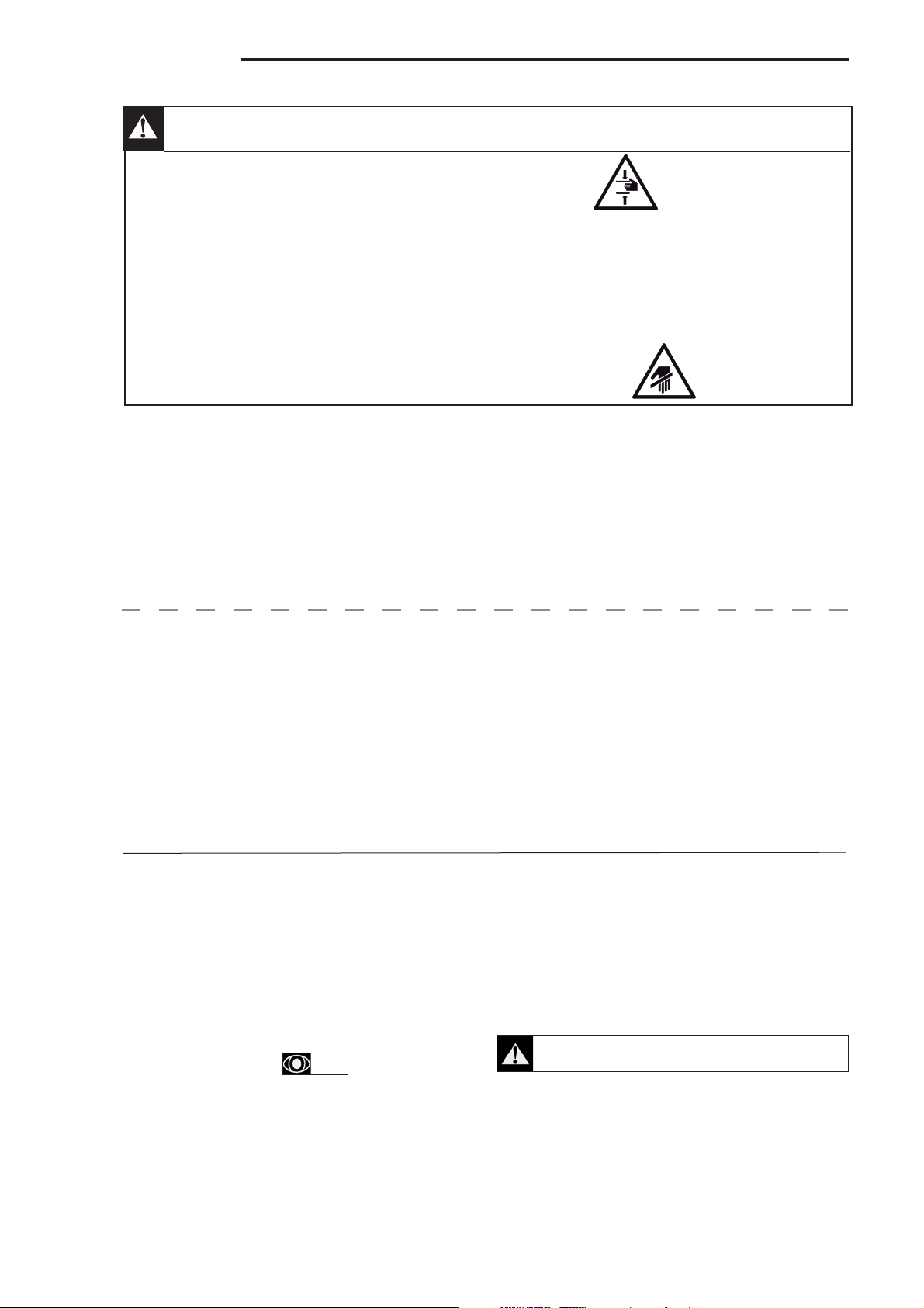
Uncontrolled closure of the lid or ram press involves a risk of crushing the fi ngers.
Never put a hand in the ejection area while the machine is in operation; risk of injury. It is strictly forbidden to put the safety systems
out of action or modify them: Risk of permanent injury!!!!
Check that the safety devices operate correctly each time before using (see paragraph on «safety system adjustments»). Never
put a hand, a hard or frozen object in the appliance
For health and safety reasons, always use a washable or disposable strong head covering that covers the hair completely.
ATTENTION: All operations, whether using, cleaning or maintenance, present risks of cuts; never force and always keep
hands a reasonable distance from cutting edges.
Always use appropriate protective equipment when carrying out these operations.
3.1.1 THE SAFETY OF THE USER is guaranteed by the following features:
ATTENTION!!
VEGETABLE SLICER
- The motor is braked to a halt when the presser lever is opened,
to allow for risk-free loading
- It is impossible to start the motor without the hopper/press
being in place.
- The dimensions of the small long vegetables hopper.
CUTTER
- The motor stops when the lid is unlocked.
- The bowl has to be in position before the appliance can be
started
- The ON button has to be pressed after the machine has been
stopped («no volt release» device)»
- The motor is braked to a halt before access to the rotor is
possible.
- Operation by holding the button pressed, in order to check on
progress with processing.
3.1.2 STARTING
• The slicer can be started if:
- the hopper is locked
- the ram press is down
• The cutter can be started if:
- The bowl is correctly positioned
- The locking pin is properly engaged (see para 3.3)
- The lid is properly locked.
a) Continuous operation:
Press button A.
The speed can be increased or decreased during operation by
pressing on button F or G.
1.2
- There is no risk connected with access to the evacuation
chute, thanks to the design of the cutting chamber, ejector
and plates.
- Compliance with the instructions given in this manual for using,
cleaning and maintaining the appliance.
- Automatic locking of the rotor during rotation thanks to the
bayonet system.
- The size of the central pouring hole that allows products to be
added when the machine is ON.
- The bowl design (leak prevention tube).
- The bowl, cover and its seal, the rotor and scraper are easy
to dismantle for cleaning.
b) Operation by holding a button pressed in:
Hold button C pressed in to be able to check on progress with
a process requiring a delicate touch.
c) Stop
Press button B
Note: Avoid stopping the cutter by unlocking the lid.
Never exceed speed 4 when operating the vegetable slicer..
Note: If the appliance is to remain stopped for several days,
disconnect it from the power supply in order not to leave the
electronic variator powered up.
3
TRK2 GB 10 06
Page 4

3.2 CHOICE OF CUTTING ACCESSORIES
3.2a
VEGETABLE SLICER
• Slicing plates C: straight cut, from 1 to 14 mm.
Note: Plate C14 is for use with screens FT or MT only.
• Slicing plates CW: wavy cut, from 2 to 6 mm for:
- Vegetables: Potatoes, carrots, aubergines, beetroot, leaf celery,
cabbage, mushrooms, cucumbers, courgettes, chicory, fennel,
onions, leeks, radishes, etc
- Fruit: Almonds, bananas, apples, etc
3.2b
• Curved plates CC: for cutting fragile and stringy products,
from 1 to 5 mm.
- Recommended for tomatoes, citrus fruit, mushrooms, shredded
salads, and all other products described opposite.
3.2c
• Shredding plates AS: for cutting matchsticks from 2 to 4 mm.
- AS 2 : fi ne 2 x 2 mm
- AS 3 : medium 3 x 3 mm
- AS 4 : big 4 x 4 mm for matchstick potatoes
«straw» potatoes,
}
celeriac, carrots
3.2d
• Grater plates J - P - K
• J 2 fi ne J 3 medium J 4 big J 7 very big J 9 very big.
- Vegetables: Carrots, «straw» potatoes, celeriac, red cabbage,
beetroot, black radish, horseradish, rösti potatoes.
- Cheese: Gruyere, mozzarella.
- Other: Walnuts, almonds, breadcrumbs, chocolate, etc
• P: For Parmesan, breadcrumbs, almonds, black radish,
chocolate.
• K: Special grater for raw potatoes (Knödeln).
3.2e
• Chipped potato screen FT: cuts from 6 to 12 mm thick in com-
bination with a C/CW plate of the same thickness.
3.2f
• Dice screen MT: cuts square sections from 5 to 20 mm in
combination with a C/CW plate for:
- Cubes or parallelepipeds: diced vegetables or fruit, mixed
vegetables, minestrone, sautéed or fried potatoes, soup.
Note: When using screen MT05, use only the small hopper with
the removable pusher
Indication of throughput (kg / h):
Crisps with C 2 250
Potatoes C 3 300
Grated carrots J 3 250
Chipped potatoes C 10 + FT 10 500
Sauteed potatoes C 14 + FT 20 600
Diced vegetables C 8 + MT 8 450
THE VARIOUS ACCESSORIES
3.2g
CUTTER
• The cutter-emulsifi er is fi tted as standard with a lid-bowl scraper,
and a rotor with to extra hard stainless steel blades (micro-serrated
blades as standard and smooth blades on option).
Note: Optional rotors suited to various types of work (see table
para 3.8). CHECK WITH US.
3.3 PUTTING INTO SERVICE / USING
! All these operations involve a risk of cuts, never apply
force and keep the hands a reasonable distance away
from the blades.
3.3
VEGETABLE SLICER
• The vegetable slicer is delivered with the ejector fi tted on the
drive shaft Press the lid lock upwards and lift the lid until the clip
stop is reached, to remove the ejector.
Before starting a task, always check that the cutting chamber,
drive shaft, ejector, plate and screen are clean. All these parts
must be washed without fail prior to using for the fi rst time.
1) To cut, slice, grate, shred
• Fit the cutting chamber.
• Fit the ejector to the fl at part of the drive shaft.
• Install the plate selected (cutter, slicer, or grater).
- Turn the plate clockwise ( ) to locate the entry point for
the bayonet, then continue in the same direction until the pin
reaches its stop.
- Close the lid and check it locks in position.
- To remove the plate, turn in the opposite direction and lift it,
using the fi nger slots located around the edge. If it stays stuck,
see para 5.3.
• It can be used as a cutter-mixer by removing the scraper from
the existing lid, or using a second lid without scraper, for the
following tasks:
- Minced meat, vegetables, etc.
- Crushed preparations, powdering.
- Kneading dough.
2) To cut chips or cubes
• Fit the cutting chamber.
• Fit the ejector (see para above).
• Place the screen selected in its place and check that it does
not rock (cleanliness of seatings).
• Then install the plate selected and close the lid.
• Recommendations: When cutting products of varying hardness using an MT screen, start by cutting the softer products,
because they will not be able to push out the cubes of harder
products that may be trapped in the screen. For hard products
such as carrots or celeriac, or other that stick, like cheese, it is
recommended to use the small hopper.
TRK2 GB 09 06
4
Page 5

CUTTER
• Before starting a job, always check on the cleanliness of the
rotor R, bowl E, lid B and its seal N, scraper P and its handle
A and the drive shaft L.
All these parts must be washed without fail prior to using for
the fi rst time.
• To use the cutter, install:
- The bowl on the central shaft, taking care to position the bowl
locking stud correctly in its housing.
- The rotor on the drive shaft, until it reaches the stop. Then
introduce the products to be processed (never do this before
installing the rotor).
- Close the lid (fi tted with its seal) on the bowl and lock it using
the handle.
The appliance is ready for operation.
• Fitting the scraper on the lid:
- Push the scraper P from below into position in the central hole
of the lid.
- Locate the pin in handle A in the slot in the scraper, and push
down until it reaches the stop.
- Hold the scraper hub with one hand and while applying pressure
on both parts, turn the handle clockwise (seen from above) to
lock them.
3.3
3.3c
• To remove the scraper:
- Hold the scraper hub with one hand and while applying
Note:
When the scraper is not used, the central hole in the lid can
closed using the plug provided with the machine .
• Always start working at low speed before increasing to a higher
speed.
• Use the button held pressed mode to start or complete any
process that requires a certain amount of supervision, or precise
degree of fi nishing.
• During work, turn the handle clockwise ( ) (seen from
above) to clean the bowl walls and lid, and to mix the product
evenly. Turn the handle clockwise ( ) then anti-clockwis
( ) with a sharp movement to detach sticky products from
the scraper.
Note:
- Liquid products or ingredients can be introduced via the chute
in the handle.
- The angled blades ensure quick and even mixing.
pressure on both parts, turn the handle anti-clockwise ( )
(seen from above) to unlock them.
Never put a hand or a hard object in the bowl while the
appliance is operating.
3.4 CHOICE AND FUNCTIONS OF THE VEGETABLE
CUTTER HOPPERS
1) Large hopper with hinged presser lever.
A Cutting slices B Thin slicing C Grating
- Passage for large products (160 x 80mm maximum, corresponding to a quartered cabbage).
• The products are loaded manually by introducing them either
one by one or by handfuls, ensuring they are correctly positioned to avoid cutting the wrong way. Wedge «fragile» products
(tomatoes, citrus fruit, etc) against the walls.
3.4a
3.4b
2) Small hopper with removable pusher.
• For cutting long products into slices (carrots, chicory, cucumbers, leeks, etc) opening maximum Ø 52 mm.
For cutting into slices, always present long products by their
pointed end.
• For manual loading, introduce the products vertically in the
little hopper, either one by one or by handfuls.
• Recommendations in order to avoid:
- Irregular, slanting cut: arrange fi ne products «top-to-tail».
- Jamming: cut off the ends of the vegetables.
3.5 USING THE LARGE HOPPER AND PRESSER LEVER
The vegetable slicer can only work if the lid is closed.
- Hold the pusher inside the presser lever which will avoid
products moving back up.
- Press the ON button
- Bring the presser lever back up
- Immediately the pusher has come out of the hopper, the motor
stops meaning that the products can be loaded in perfect
safety.
- When the lever moves down, the vegetable slicer starts again
automatically.
3.5b
3.5c
3.5a
For cutting and slicing.
- Using the presser lever, push the products down the hopper
until the bottom stop is reached, applying just the right amount
of pressure on the presser lever.
- Bring the presser lever back up again and start a new cycle.
- When work has fi nished, push the STOP button.
Note: Apply the right amount of pressure on the presser lever,
according to:
- the product being processed (soft product = small amount of
pressure),
- the cutting accessory chosen (a grater requires more pressure
than a slicing plate).
3.4c
3.6 USING THE SMALL FEED HOPPER AND PUSHER
- Leave the presser lever in the low position and unlock the
pusher.
- Press the ON button to start
- Remove the pusher with one hand and introduce the products
with the other.
- Push the products with the pusher and start a new cycle.
- When work has fi nished, push the STOP button.
5
3.6
Never put a hand or a hard object in a hopper with the machine
turned on.
TRK2 GB 09 06
Page 6

3.7 A FEW WORKING EXAMPLES (QUANTITIES ARE GIVEN AS AN INDICATION ONLY)
CUTTER
! Never process hard products (whole vegetables, lumps
of meat, etc) with the scraper in position. It would be liable
to be damaged.
Quantity of fi nished product by weight
Qty Type of blade K45 VV K55 VV K70 VV
Sausage meat min smooth 100 g 100 g 200 g
max smooth 1.5 kg 2 kg 25 kg
Minced meat/
steak «tartar» min smooth 100 g 100 g 200 g
max smooth 1.5 kg 2 kg 2.5 kg
Onion min smooth 150 g 150 g 150 g
max smooth 1.5 kg 2 kg 2.5 kg
Parsley min smooth 1 bunch (about 100 g) 1 bunch (about 100 g) 1 bunch (about 100 g)
max smooth
Mayonnaise min any 100 g 150 g 150 g
max any 2 kg 2.5 kg 3.5 kg
Emulsifi ed carrots min
max
Garlic and parsley
butte
r max smooth 1,5 kg 1,8 kg 2,5 kg
Shortcrust pastry
max
Dough (fl our and
water paste
60 % humidity)
Almonds or
min
min any 160 g 160 g 160 g
min
Microserrated
Microserrated
min smooth 200 g 300 g 300 g
Microserrated
Microserrated
max any 2 kg 2.4 kg 3 kg
Microserrated
3 bunches (about 300 g) 4 bunches (about 400 g) 5 bunches (about 500 g)
600 g 600 g 1 kg
1 kg 1,5 kg 2,5 kg
150 g 160 g 160 g
1.3 kg 1.7 kg 2.5 kg
100 g 00 g 200 g
TRK2 GB 09 06
hazelnuts
Parmesan min smooth 100 g 100 g 200 g
max smooth 750 g 1 kg 1.5 kg
max
Microserrated
1 kg 1.5 kg 2 kg
6
Page 7

Cleaning, hygiene, storage
Before dismantling any part, disconnect the appliance from the power supply.
Before using any cleaning product, be sure to read the instruction and safety instructions accompanying the product and use
appropriate protective equipment.
Do not clean the machine with a pressure cleaner
Take care when handling the rotor, screens and plates. (Risk of CUTS – ELECTRIC SHOCK).
4.1 BETWEEN TWO SESSIONS
VEGETABLE SLICER
- Remove the cutting accessories (plate, screen, ejector) and
the pusher.
- Remove the cutting chamber.
- Remove the hopper-lid and the presser lever, in accordance
with the following instructions:
c Lift the pusher until it slips into the clipped position.
(This is the only position in which the locking pin can be locked/unlocked).
4.1a
ATTENTION!!
d Unlock the pin by pulling about 2cm.
e Lower the pusher to make it easier to remove the assembly
f Remove the locking pin completely.
g The hopper-lid and lid-pusher assembly can be removed.
- Wash the equipment in hot water, rinse and dry.
- Clean the body using a clean, damp sponge.
• The cutting chamber, hopper and presser lever can be washed
in a dishwasher.
CUTTER
• Remove the bowl, lid with its seal, scraper and rotor (see
para 3.3).
• To dismantle the lid:
- Unlock the lid using handle C.
- Open the lid until it reaches the rear stop
- Remove the locking pin
- Remove the lid
• Use the slot at the rear of the lid to remove seal N.
• To re-assemble, follow the same procedure in reverse order,
taking care to push the locking pin completely home when the
lid is in the fully open position.
4.1b
• Lift bowl E vertically using its handle D, rotor R will unlock
automatically The rotor can also be removed separately.
• Clean the above parts under a tap or in a sink using hot water
and a detergent-disinfectant product or greaser (if working with
greasy products).
• Check that the various parts have been cleaned correctly.
Note:
- Use cleaning products that are compatible with the plastic
(polycarbonate) and stainless steel parts.
- Do not use abrasive products to clean the transparent lid.
4.2 AFTER USE
VEGETABLE SLICER
- See para 4.1.
- Clean removable parts with hot water and a detergent-degreaser-disinfectant compatible with the material the parts
are made of.
- Rinse with clean water and leave to dry.
Recommendation : For the MT screens, push out any trapped
dice using a carrot. Do not use any metal implements.
4.2
4.2
- Clean the outside of the vegetable slicer using a damp sponge
Note:
- Do not use abrasive detergents which scratch the surfaces, nor
any containing chlorine which dulls the aluminium.
CUTTER
• To dismantle and clean the bowl, scraper and rotor, see para
4.1.
• If needed, clean the outside of the machine using a damp
sponge and a detergent-disinfectant product, paying particular
attention to the rotor drive shaft, the bowl seating area and the
slot that takes the bowl positioning lug, the rinse.
Note:
- Use cleaning products that are compatible with the materials
from which the appliance is made.
- The drive shaft and inside of the rotor must be kept perfectly
clean.
- The bowl, lid and scraper can be put in the dishwasher, together
- In order to avoid any acid marking the rotor blades, it is re-
- After cleaning the lid, do not lock it in position. By allowing
and mild detergent, then rinse using a clean sponge.
with the rotor provided the blades are protected against any
impact.
commended to dry them thoroughly prior to storage, and to
keep the rotor in the cold chamber in order to keep microbial
development to a minimum .
the air to circulate freely there will be no condensation nor
concentration of any remaining smells
4.3 STORAGE
- After cleaning, store each cutting accessory in the storage
rack fi xed to the wall.
4.3
7
TRK2 GB 09 06
Page 8

Fault fi nding
5.1 IF THE APPLIANCE WON’T START, CHECK THAT:
• The machine is connected to the power supply.
• The power supply to the socket is correct.
• The bowl is in position.(Cutter)
• The hopper is properly locked.(Vegetable slicer)
• The presser lever is completely down.(Vegetable slicer)
5.2 ABNORMAL NOISE:
• Stop the appliance.
• Check that the plate, screen and ejector are correctly positioned.
• Dismantle, clean if necessary and re-assemble.
• If the noise persists, and if the appliance lacks power, check
that:
- The motor phases are correctly connected.
5.3 PLATE JAMMED: VEGETABLE SLICER
- Disconnect the appliance.
- Place one hand fl at on the ejector and prevent it from rotating.
5.3a
• The lid is locked properly (Cutter).
• The pin is pushed fully home (see para 4.1).
• If the appliance stops in the middle of a task:
- The motor heat sensor has been triggered. Wait a few minutes
before starting up again.
- Reduce the quantity of product and/or speed.
• Check:
- That the bowl, rotor and scraper are correctly positioned.
- hat there are no foreign bodies inside the bowl.
• Dismantle, clean if necessary and re-assemble.
If the problem persists, check with your supplier’s maintenance
service
- With the other hand, take hold of the outer part of the plate using
the fi nger holds, and move anticlockwise ( ) sharply.
- Lift the plate, rocking it backwards and forwards in the direction
of rotation.
5.3b
5.4 WORK QUALITY
VEGETABLE SLICER
• Before any intervention, stop the machine.
• If the products are not being discharged correctly, check
that:
- The ejector is fi tted correctly.
- The products in the collection container are not blocking the
exit.
- There is no build-up of products in the cutting chamber.
• If the quality of cut is not up to standard, check:
- That the direction of rotation is correct (anticlockwise ( )
- The correct speed has been selected (depending on model).
- The right cutting accessories have been chosen (see para
- The condition of the cutting accessories.
- The choice of hopper.
- The way the products are presented inside the hopper (see
CUTTER
• In order to obtain impeccable quality of work, quickly and
without heating:
- Use blades that are always well-sharpened and have not been
the subject of knocks.
- Keep a spare rotor ready for delicate work (e.g.: chopping
parsley with smooth blades, kneading with serrated blades).
- Avoid working with excessive quantities of products which will
Note:
- The microserrated blades combine the qualities of a smooth and
a serrated blade, meaning they need sharpening less often.
- If necessary, restore the cutting edge by using a whetstone on
the opposite side from the grinding.
seen from above).
3.2).
para 3-4)
result in them becoming heated (meat, dough).
TRK2 GB 09 06
8
Page 9

Maintenance
Maintenance may only be carried out by a qualifi ed, trained and authorised person.
6.1 MECHANICAL PARTS
• The appliance requires only minimum maintenance (the bea-
rings, motor and mechanical parts are greased for life).
6.2 MAINTENANCE OF CUTTING ACCESSORIES
• Slicing plates: resharpening the blades
- Remove the fi xing screws,
- Use a grinder with water, taking care to keep the same cutting
angle.
• Chipped potato screen.
The blades cannot be changed because they are overmoulded
and tensioned for life.
- If needed, use a soft stone to restore the cutting edge.
• Dicing screen.
The blades cannot be changed because they are overmoulded
and tensioned for life.
ATTENTION!!
• It is recommended to lubricate the seal located at the base of
the drive shaft once a year using food quality grease.
- If needed use a small fi le if the blades have been damaged
after a knock.
• Graters.
Graters are not resharpened.
- If the hollows in the grater are badly worn, change the cup.
• Cutter rotor.
- Ensure that the blades remain properly sharpened because
the quality of cutting depends on this (especially for meat).
6.3 ADJUSTMENT TO SAFETY FEATURES
• The safety features must be checked frequently for correct
operation. The motor must stop in less than 2 seconds when the
speed setting is between 1 and 4, and in less than 4 seconds
when the speed is above 4.
- When the lid is opened the motor should not start if the lid is
not properly closed (lock clipped into place),
6.4 ELECTRICAL COMPONENTS
• Access to electrical components:
- Disconnect the machine and turn it over.
- Dismantle the casing (4 screws – size 7 spanner).
! Residual voltage at the capacitor terminals.
• The capacitors may still have an electric charge.
In order to avoid any risk when carrying out an intervention, it is
recommended to discharge them by connecting their terminals
using an insulated conductor (e.g. screwdriver).
See the electrical diagrams at the end of these instructions
6.3
- When the presser lever is lifted, dimension F at 45 mm max
• If one of these two safety functions is not implemented:
- Do not use the appliance.
- Have it adjusted by your local dealer’s service department.
• Identifi cation of the wire colours:
- Motor: A: red - B: green - C: yellow - D: white - E: blue -
- Phases: L Single phase; - Neutral: N
- Earth: Green/Yellow B/C
• Component identifi cation:
S1 : Lid safety
S2 : Bowl safety
S6 : Speed safety
S5 : Locking pin safety
M : Motor
V : Variator
CC : Control board
X : Power supply cord :
from the edge of the hopper.
F: black - G: orange - H: purple - I: grey - J: brown - K: pink
6.5 ADDRESS FOR MAINTENANCE
We recommend that you contact fi rst the seller of the machine
fi rst of all.
! For all requests for information or orders for spare parts,
quote the type of machine, the serial number and the
electrical specifi cations.
The manufacturer reserves the right to modify and make improvements to the products without giving prior warning.
Supplier’s stamp
Date of purchase: ...............................................
9
TRK2 GB 05 07
Page 10

Compliance with legislation
The machine is designed and made in compliance with:
- The machine directive 2006/42 EEC,
- The CEM directive 2004/108 EEC,
- The low voltage directive 2006/95/EEC,
- The machine recycling directive 2002/95/EEC
- The «WEEE» directive 2002/96/EEC
The symbol “ ” on the product indicates that this product
must not be treated as household waste. On the contrary, it must
be taken to an electric and electronic equipment recycling point.
By ensuring that the product is properly disposed of in this way,
you are helping to prevent damage to the environment and human
health that could otherwise occur if the product is not disposed of
in a controlled manner. For more information about the recycling
of this product, please contact the sales department or supplier
of the product, the after sales service or the appropriate waste
treatment services.
- The «waste» directive 2006/12/EEC
The machine is designed in order to contribute as little as possible, if at all, to the quantity and noxious nature of waste and
risks of pollution.
Please comply with the recycling conditions.
- The «packaging and packaging waste» directive 94/62/
EEC
The machine packaging is designed in order to contribute as
little as possible, if at all, to the quantity and noxious nature of
waste and risks of pollution.
Please make sure the various packaging materials are disposed
of in the appropriate recycling points.
- European standards:
EN 6O 204-1-2006 Machine electrical equipment.
EN 1678-1998 vegetable cutting machines, integral safety.
EN 12852- Food processing machinery. Regulations relating to
safety and hygiene.
This compliance is certifi ed by:
- The CE conformity mark, attached to the machine.
- The corresponding CE declaration of conformity, associated
with the warranty.
- This instruction manual, which must be given to the operator.
Acoustic specifi cations:
- The acoustic pressure level measured in accordance with the
test code EN ISO 3744 and EN ISO 11201 is 73 dBA under
the conditions specifi ed in standard EN 1678 : 1998 (use of
a fi ne grater for processing raw, unpeeled potatoes). When
empty, or with the cutter, the level is < 70 dBA.
Protection indexes according to standard EN 60529-2000:
- Electrical controls IP55
- Machine as a whole IP34
Built-in safety:
- The machine has been designed and manufactured in compliance with the relevant regulations and standards referred
to above.
- Before using the machine, the operator must be trained in its
use and informed of any possible residual risks.
Food hygiene:
The machine is made of materials that comply with the following
legislation and standards:
- Directive 1935/2004/EEC: materials and articles intended to
come in contact with food,
- Standards EN 601-2004: moulded aluminium alloys in contact
with food.
The surfaces of the food area are smooth and easy to clean. Use
detergents that are approved for food hygiene and respect the
instructions for their use.
TRK2 GB 02 07
10
 Loading...