

Page 1
U19 All Refrigerator and All Freezer Trim Kit Installation
Product Line: U19 All Refrigerator and All Freezer Models
Serial Number Range: All Serial number ranges
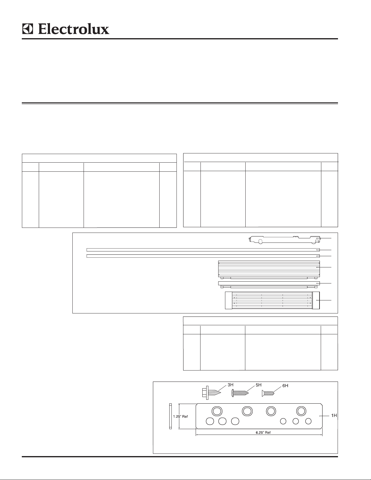
Single Trim Kit Components
INSTRUCTION SHEET
Parts Included in Kit TRIMKITEZ1 (Part# 808739901):
Kit for Frigidaire Models
Single Trim Kit 808739901
ITEM PART NUMBER DESCRIPTION QTY
1 808657301 Trim Side RH U19 1
2 808657302 Trim Side LH U19 1
3 808657602 Trim Top Short U19 Single 1
4 808667402 Trim Top Tall U19 Single 1
5 808709902 Kick Plate U19 Single 1
6 297337700 Carton, Packaging 1
7 A00350301 Hardware Pack Single U19 1
8 297276900 Leveler Assembly Support System 2
Single Trim Kit
Parts Included in Kit TRIMKITSS1 (Part# 808739902):
Kit for Electrolux Models
Single Trim Kit 808739902
ITEM PART NUMBER DESCRIPTION QTY
1 808657303 Trim Side RH U19 1
2 808657304 Trim Side LH U19 1
3 808657604 Trim Top Short U19 Single 1
4 808667404 Trim Top Tall U19 Single 1
5 808709904 Kick Plate U19 Sngle 1
6 297337700 Carton, Packaging 1
7 A00350301 Hardware Pack Single U19 1
8 297276900 Leveler Assembly Support System 2
Front View
8
1
2
4
3
5
NOTE: All Hardware Pack components mentioned
throughout this instruction sheet will have an “H”
after the item number.
Hardware Pack A00350301
Hardware Pack A00350301
ITEM PART NUMBER DESCRIPTION QTY
1H 297333900 Tie-Bar Hinge 1
3H 297236250 Screw 1/4-20 x .63 8
5H 050149 Screw TH #8-18 x .75 AB 6
6H 297142600 Screw FH #8-32 x .63 2
7H A00343901 Installation Instructions 1
©2013 Electrolux Home Products, Inc. Instruction Sheet A00343901 11.04.13
Page 2
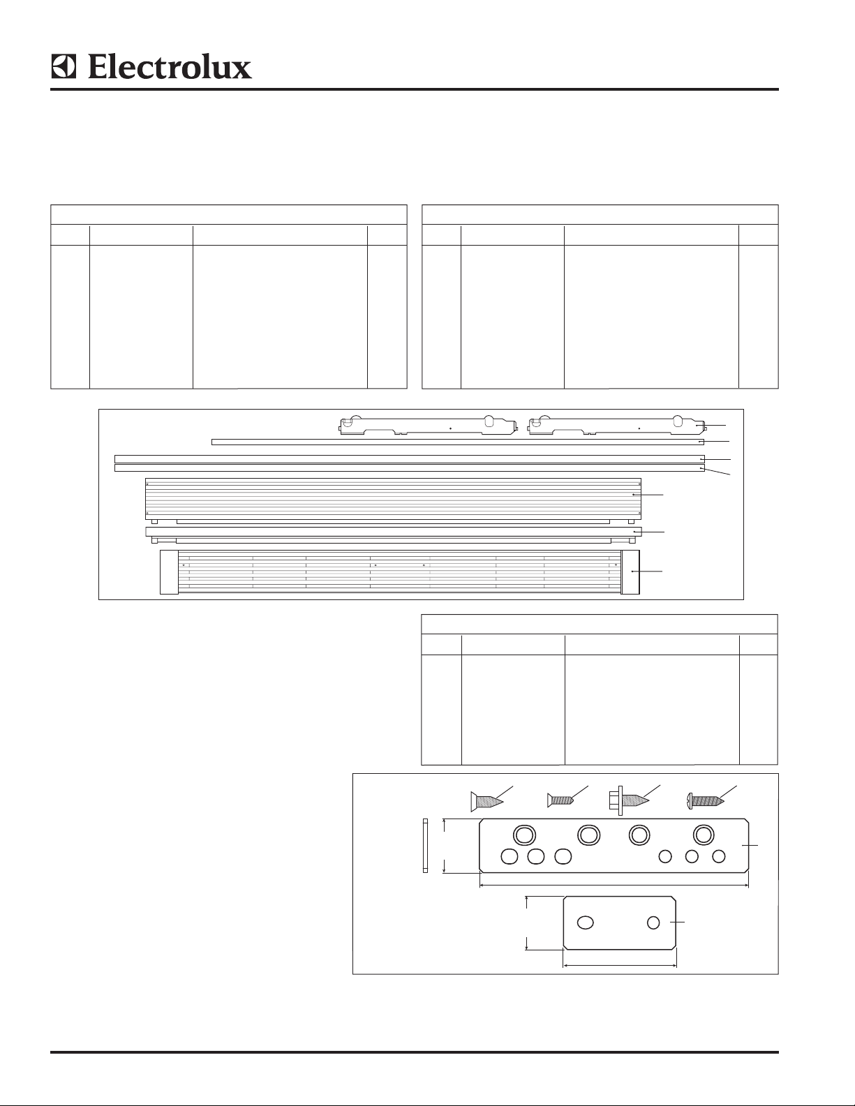
1.25”
Ref
1.25”
Ref
6.25” Ref
2.62” Ref
1H
2H
3H4H 5H6H
Dual Trim Kit Components
INSTRUCTION SHEET
Parts Included in Kit TRIMKITEZ2 (Part# 808743701):
Kit for Frigidaire Models
Double Trim Kit 808743701
ITEM PART NUMBER DESCRIPTION QTY
1 808674501 Center Trim U19 1
2 808676201 Trim Side RH U19 1
3 808676202 Trim Side LH U19 1
4 808657601 Trim Top Short U19 Dual 1
5 808667401 Trim Top Tall U19 Dual 1
6 808709901 Kick Plate U19 Dual 1
7 297337700 Carton, Packaging 1
8 A00350302 Hardware Pack Dual U19 1
9 297276900 Leveler Assembly Support System 4
Double Trim Kit
Front View
Parts Included in Kit TRIMKITSS2 (Part# 808743702):
Kit for Electrolux Models
Double Trim Kit 808743702
ITEM PART NUMBER DESCRIPTION QTY
1 808674501 Center Trim U19 1
2 808676203 Trim Side RH U19 1
3 808676204 Trim Side LH U19 1
4 808657603 Trim Top Short U19 Dual 1
5 808667403 Trim Top Tall U19 Dual 1
6 808709903 Kick Plate U19 Dual 1
7 297337700 Carton, Packaging 1
8 A00350302 Hardware Pack Dual U19 1
9 297276900 Leveler Assembly Support System 4
9
1
2
3
5
4
NOTE: All Hardware Pack components mentioned
throughout this instruction sheet will have an “H”
after the item number.
Hardware Pack A00350302
6
Hardware Pack A00350302
ITEM PART NUMBER DESCRIPTION QTY
1H 297333900 Tie-Bar Hinge 2
2H 297333901 Tie-Bar Back 1
3H 297236250 Screw 1/4-20 x .63 18
4H 297337000 Screw FH 1/4-20 x .63 4
5H 050149 Screw TH #8-18 x .75 AB 8
6H 297142600 Screw FH #8-32 x .63 2
7H A00343901 Installation Instructions 1
©2013 Electrolux Home Products, Inc. Instruction Sheet A00343901 11.04.13
Page 3
INSTRUCTION SHEET
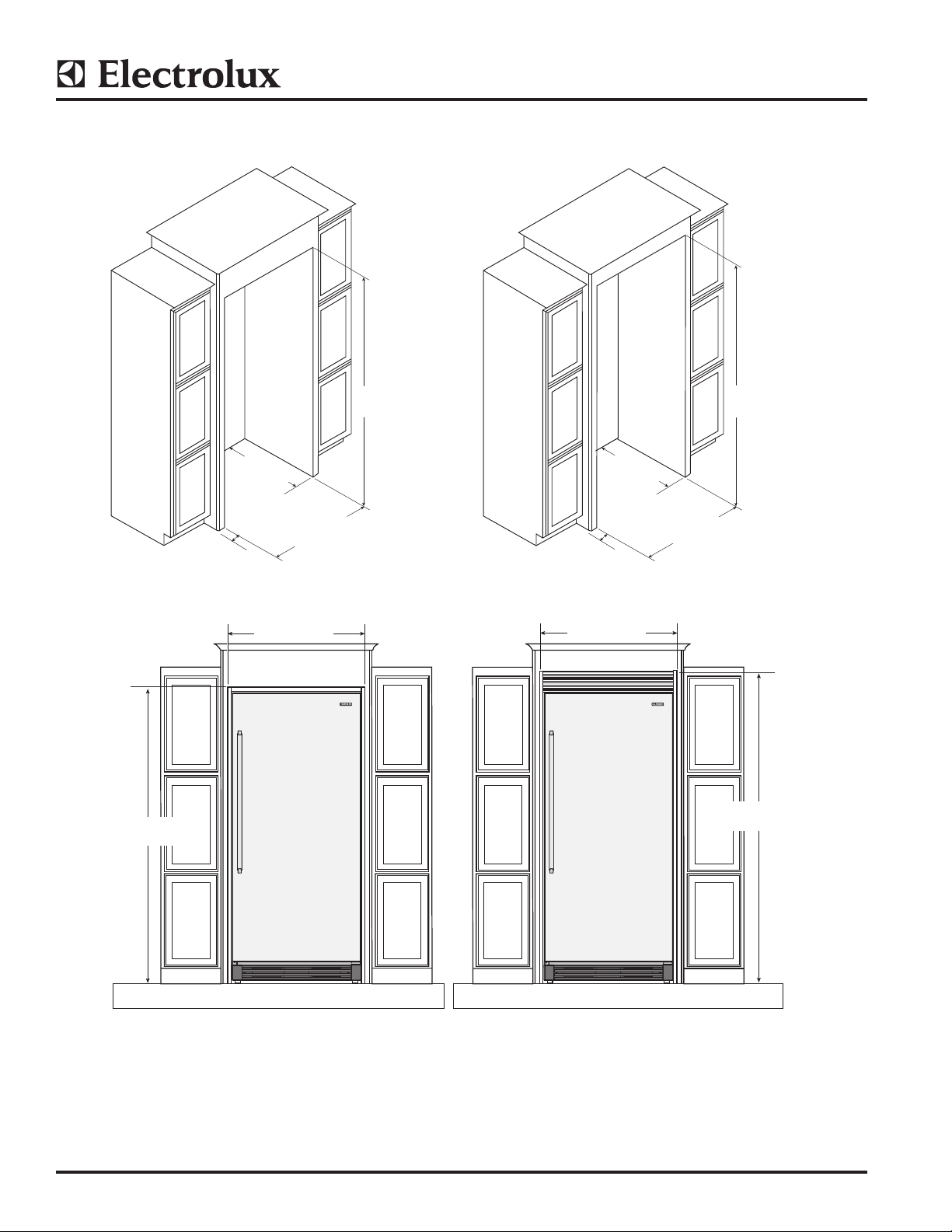
TRIMKITEZ1 (Part# 808739901) & TRIMKITSS1 (Part# 808739902) Trim Kit Dimensions
75.09”
(1907 mm)
0.75”
(19.05 mm)
(min.)
25.25”
(641mm)
(min.)
(882 mm)
33.00 ± .032”
(838 ± .8mm)
34.74”
75.00 ± .06”
(1905 mm)
0.75”
(19.05 mm)
(min.)
34.74”
(882 mm)
79.00 ± .06”
(2006.5 ± 1.5mm)
25.25”
(641mm)
(min.)
33.00 ± .032”
(838 ± .8mm)
79.09”
(2009 mm)
©2013 Electrolux Home Products, Inc. Instruction Sheet A00343901 11.04.13
Page 4
INSTRUCTION SHEET
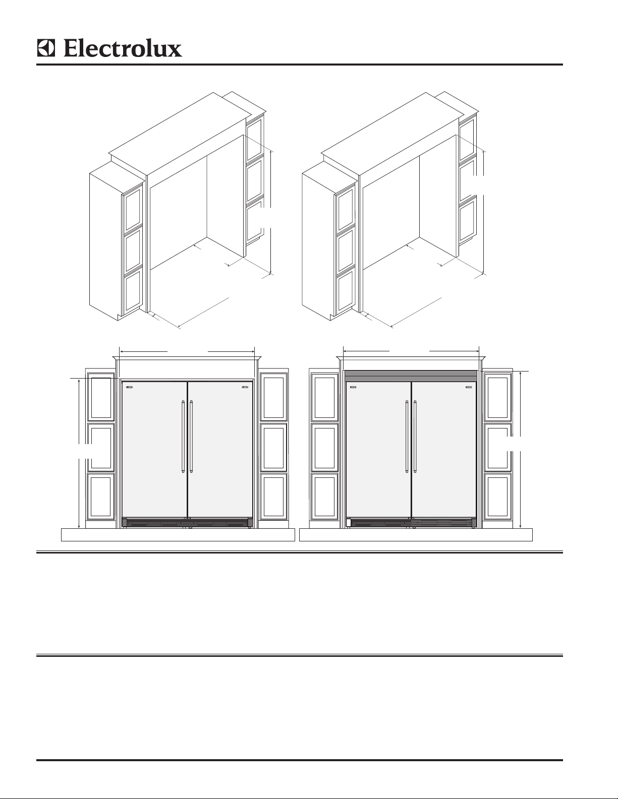
67.12”
TRIMKITEZ2 (Part# 808743701) & TRIMKITSS2 (Part# 808743702) Trim Kit Dimensions
(2006.5 ± 1.5mm)
75.00 ± .06”
(1905 mm)
”
79.00 ± .06”
75.09”
(1907 mm)
0.75”
(19.05 mm)
(min.)
(641mm)
67.12”
(1705 mm)
25.25”
min.
66.00 ± .032
(1676.4 ± .8mm)
0.75”
(19.05 mm)
(min.)
25.25”
(641mm)
min.
(1705 mm)
66.00 ± .032
(1676.4 ± .8mm)
79.09”
(2009 mm)
Safety: Always wear safety glasses when using power tools.
Tools Needed:
• PhillipsTM Screwdriver • Adjustable Wrench to t 1-¼” • Step Ladder
• Flathead Screwdriver • 3/8” Socket Wrench • Tape Measure (min. 7” length)
• Safety Glasses • 7/16” Socket Wrench • Drill & 1/8” Bit
Before You Begin
• Be careful when unpacking components. Do not use sharp objects when removing packaging material. This may
scratch the surface of trim components.
• Use extreme care when handling the metal trim pieces. Corners are very sharp and easily damaged if dropped.
©2013 Electrolux Home Products, Inc. Instruction Sheet A00343901 11.04.13
Page 5
INSTRUCTION SHEET
Setting Up The Trim And Grill Assembly
(Single and Dual Installations)
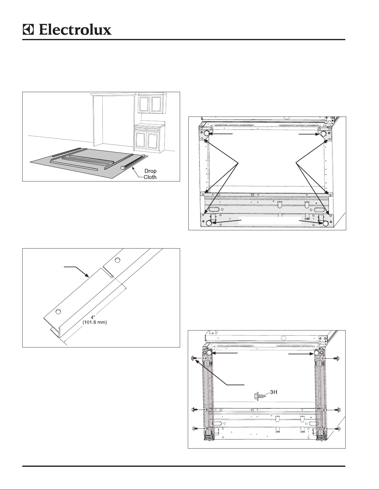
1. Lay the parts out on a cleared area face down. Be
sure to place a drop cloth over the floor to prevent
scratching trim kit and/or floor. (See Figure 1).
Figure 1
2. Cut 4” (101.6 mm) off the left and right Side Trim using
the slot as a guide to make the proper size for a 75”
(1905 mm) cut-out. (See Figure 2).
Leveling System Install
(Single and Dual Installations)
3. a. Lie unit on its back on packaging material or a
drop cloth to prevent damage.
b. Remove (3) screws from each side and discard.
(See Figure 3)
c. Remove and save both plastic leg levelers to use
in the next step.
Remove Leg Levelers
Remove And Discard
Screws
Remove Leg Levelers
NOTE: DO NOT cut the side trim if installing in a 79”
(2006 mm) opening.
Side Trim
Left and Right
Sides
Figure 2
Figure 3
4. a. Attach the current leg leveler to leveling system.
The leg leveler is a common part that will work
on both bottom sides of the unit. (See Figure 4).
b. Attach leg leveler with three (3) screws per side
using a 3/8 socket.
c. Re-install the leg levelers.
d. In order to provide clearance to access the rear
screw hole, adjust the rear roller up out of he
way. When finished, lower the rear roller back to
its initial position.
Install Leg Levelers
Install Screws
(3 per side)
Figure 4
©2013 Electrolux Home Products, Inc. Instruction Sheet A00343901 11.04.13
Page 6
Trim Kit Installation
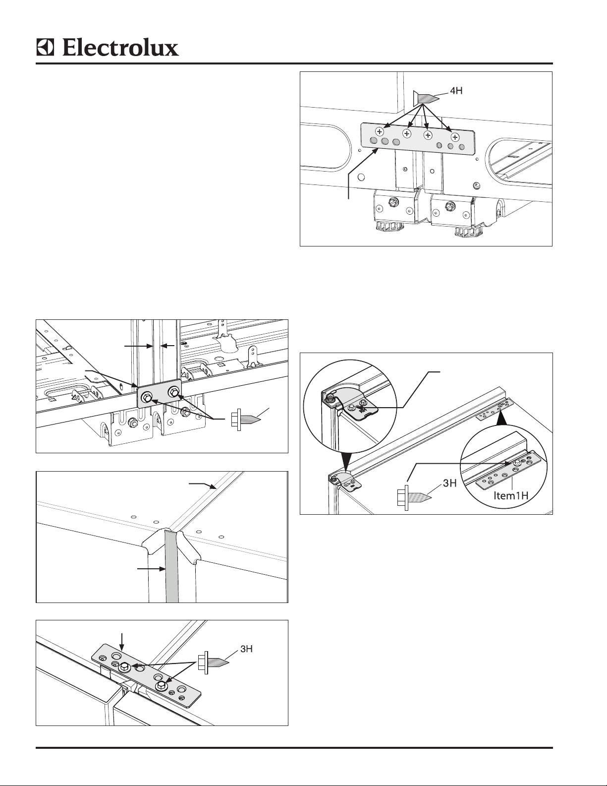
Installing Trim Kit Tie Bar
(Dual Installation Only)
NOTE: Leveling may be required to line up the holes
in steps “a” and “d”.
5. a. Tie units together by securing the mounting
bracket at the back of the units with a
3/8” socket. (See Figure 5).
b. Install center strip to insure the proper 3/8” gap
is maintained between units. (See Figure 6).
c. Tie units together with the common mounting
bracket at the front top with two screws in
the inner two screw holes by using a 3/8” socket.
(See Figure 7).
d. Tie units together with common mounting
bracket at the bottom front using #3 Phillips
driver. (See Figure 8).
3/8” Gap
INSTRUCTION SHEET
Item 1H
Figure 8
Trim Kit Installation (Single Unit Installation)
6. Remove outer screw from top hinge using a 3/8”
socket driver or wrench and save for later. Install
mounting bracket with one screw mounted to inside
hole using a 3/8” socket. (See Figure 9).
Item 2H
3/8” Center Strip
Item 1 Dual kit
Figure 5
3/8” Gap Between Units
Figure 6
Item 1H
Remove Screw
3
H
Figure 9
Side Trim Installation
(Single and Dual Installations)
7. a. Position Left Hand Side Trim on cabinet trim with
bottom resting on the floor.
b. Drill the 1/8” (3mm) pilot hole.
c. Run screw in all the way and then back out.
Remove side trim for later install. (See Figure 10).
NOTE: Some cabinet substrates may require predrilling holes using a 1/8” (3 mm) diameter drill bit.
Figure 7.
©2013 Electrolux Home Products, Inc. Instruction Sheet A00343901 11.04.13
Page 7
INSTRUCTION SHEET
8. a. Position Right Hand Side Trim on cabinet trim
with bottom resting on the floor.
b. Drill the 1/8” (3 mm) pilot hole.
c. Run screw in all the way and then back out.
Remove side trim for later install. (See Figure 10).
H
Figure 10
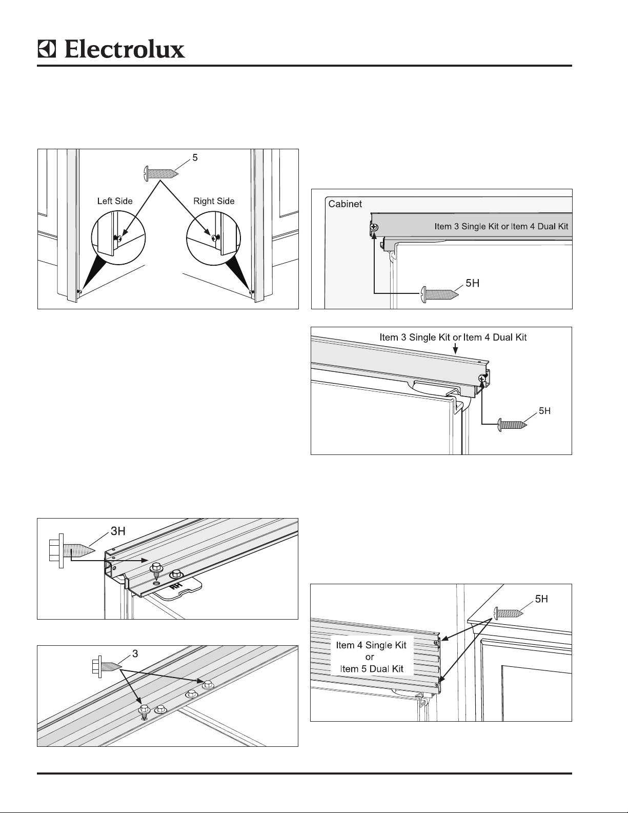
Top Trim Install
(Single and Dual Installations)
NOTE: Step ladder required for installing top
trim components.
10. 75” (1905 mm) High Opening With Top Trim
(Single and Dual Installations)
a. Slide units into place. Adjust height so top trim
height reaches 75.09” (1907 mm). Center units
in opening and level. (See Step 12 for leveling
instructions) (See Figures 13 and 14).
b. Drill 1/8” (3 mm) pilot holes and fasten screws
with a Phillips driver to kitchen cabinets.
Figure 13
9. a. Remove outer hinge screw common on both
sides for a dual installation, (for a single
installation this screw is removed in Step 6.
Align the top trim and attach with a 3/8” socket.
Repeat for opposite side. (See Figure 11).
b. (Dual installation only) Install outer screws on
common mounting bracket, align top trim
and attach with 3/8” socket. (See Figure 12).
Figure 11
H
Figure 14
11. 79” (2006 mm) High Opening With Louvered Top
Trim (Single and Dual Installations)
a. Slide units into place. Adjust height so top trim
height reaches 79.09” (2009 mm). Center units
in opening and level. (See Figure 15)
b. Drill 1/8” pilot holes and fasten two (2) screws
per side with a Phillips driver to kitchen cabinets.
Figure 12
Figure 15
©2013 Electrolux Home Products, Inc. Instruction Sheet A00343901 11.04.13
Page 8
INSTRUCTION SHEET
12. Trim Kit Leveling (See Figure 16)
(Single and Dual Installations)
a. To raise front of unit, turn leg leveler to left with
adjustable wrench to fit 1-¼” hex.
b. To raise back of unit, adjust bolt clockwise with
3/8” socket or flat head screwdriver.
To raise or lower door,
adjust 7/16” bolt.
3/8” Bolts
Phillips Head
Screws
To raise back of
unit, adjust bolt
clockwise.
Leg Leveler
Figure 16
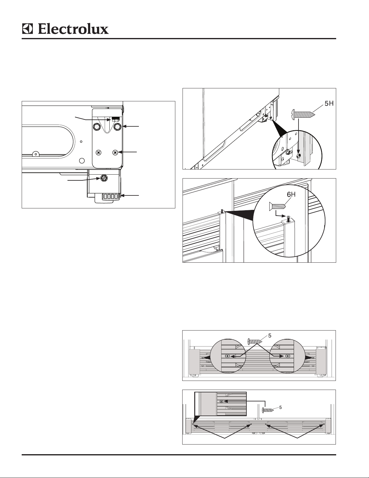
14. Side Trim Attachment to Kitchen Cabinets
(Single and Dual Installations)
a. Fasten bottom of side trim with screw.
(See Figure 17).
b. Fasten screws to top trim. (See Figure 18).
Figure 17
13. Hinge Adjustment (See Figure 16)
(Single and Dual Installations)
a. The bottom hinge is designed to make final
minor adjustments for door to door and door to
cabinet alignment.
b. Hinge will move side to side 3/32” and raise
up 1/8”.
Use a 7/16” socket or open end wrench to raise or
lower the door.
Use a 3/8” socket and a Phillips screwdriver to loosen
bottom hinge. Shift door left or right, then retighten
screws and bolts.
Figure 18
15. Kick Plate Attachment
(Single Unit) Attach the kick plate to the cabinet
with two (2) screws. (See Figure 19).
(Dual Unit) Attach the kick plate to the cabinet
with four (4) screws. (See Figure 20).
Figure 19
Screws
Screws
Figure 20
©2013 Electrolux Home Products, Inc. Instruction Sheet A00343901 11.04.13
Page 9

HOJA DE INSTRUCCIONES
1,25” Ref.
6,25” Ref.
1H
3H
5H
6H
Instalación del kit de molduras de todos los congeladores y refrigeradores U19
Línea de productos: modelos de todos los congeladores y refrigeradores U19
Rango de número de serie: todos los números de serie
Componentes del kit de monturas simples
Piezas incluidas en el kit TRIMKITEZ1
(pieza n.º 808739901) :
Kit para los modelos Frigidaire
Piezas incluidas en el kit TRIMKITSS1
(pieza n.º 808739902) :
Kit para los modelos Electrolux
Kit de molduras simples 808739901
ART. N.º DE PIEZA DESCRIPCIÓN CANT
1 808657301 Moldura lateral RH U19 1
2 808657302 Moldura lateral LH U19 1
3 808657602 Moldura superior corta
U19 simple
4 808667402 Moldura superior alta U19
simple
5 808709902 Placa de protección
U19 simple
6 297337700 Embalaje de cartón 1
7 A00350301 Paquete de accesorios
simples U19
8 297276900 Sistema de soporte de
montaje del nivelador
Kit de molduras simples
1
1
1
1
2
Kit de molduras simples 808739902
ART. N.º DE PIEZA DESCRIPCIÓN CANT
1 808657303 Moldura lateral RH U19 1
2 808657304 Moldura lateral LH U19 1
3 808657604 Moldura superior corta
U19 simple
4 808667404 Moldura superior alta U19
simple
5 808709904 Placa de protección
U19 simple
6 297337700 Embalaje de cartón 1
7 A00350301 Paquete de accesorios
simples U19
8 297276900 Sistema de soporte de
montaje del nivelador
Vista frontal
1
1
1
1
2
NOTA: Todos los componentes del Paquete de
accesorios mencionados en toda esta hoja de
instrucciones tendrán una letra “H” posterior al
número de artículo.
Paquete de accesorios A00350301
Paquete de accesorios A00350301
ART. N.º DE PIEZA DESCRIPCIÓN CANT
1H 297333900 Bisagra de la barra
de unión
3H 297236250 Tornillo 1/4-20 x 0,63 8
5H 050149 Tornillo TH #8-18 x 0,75 AB 6
6H 297142600 Tornillo FH #8-32 x 0,63 2
7H A00343901 Instrucciones de
instalación
©2013 Electrolux Home Products, Inc. Hoja de instrucciones A00343901 11.04.13
1
1
Page 10

HOJA DE INSTRUCCIONES
1,25”
Ref.
1,25”
Ref.
6,25” Ref.
2,62” Ref.
1H
2H
3H4H 5H6H
Componentes del kit de molduras dobles
Piezas incluidas en el kit TRIMKITEZ2
(Pieza N.º 808743701) :
Kit para los modelos Frigidaire
Kit de molduras dobles 808743701
ART. N.º DE PIEZA DESCRIPCIÓN CANT.
1 808674501 Moldura central U19 1
2 808676201 Moldura lateral RH U19 1
3 808676202 Moldura lateral LH U19 1
4 808657601 Moldura superior corta
5 808667401 Moldura superior alta U19
6 808709901 Placa de protección
7 297337700 Embalaje de cartón 1
8 A00350302 Paquete de accesorios
9 297276900 Sistema de soporte de
Vista frontal
U19 doble
doble
U19 doble
doble U19
montaje del nivelador
Kit de molduras dobles
Front View
Piezas incluidas en el kit TRIMKITSS2
(Pieza N.º 808743702) :
Kit para los modelos Electrolux
Kit de molduras dobles 808743702
ART. N.º DE PIEZA DESCRIPCIÓN CANT.
1 808674501 Moldura central U19 1
2 808676203 Moldura lateral RH U19 1
3 808676204 Moldura lateral LH U19 1
1
1
1
1
4
4 808657603 Moldura superior corta
U19 doble
5 808667403 Moldura superior alta U19
doble
6 808709903 Placa de protección
U19 doble
7 297337700 Embalaje de cartón 1
8 A00350302 Paquete de accesorios
doble U19
9 297276900 Sistema de soporte de
montaje del nivelador
5
1
1
1
1
4
9
1
2
3
NOTA: Todos los componentes del Paquete de
accesorios mencionados en toda esta hoja de instrucciones tendrán una letra “H” posterior al número
de artículo.
4
6
Paquete de accesorios A00350302
ART. N.º DE PIEZA DESCRIPCIÓN CANT.
1H 297333900 Bisagra de la barra
de unión
2H 297333901 Parte posterior de la barra
de unión
3H 297236250 Tornillo 1/4-20 x 0,63 14
4H 297337000 Tornillo FH 1/4-20 x 0,63 4
5H 050149 Tornillo TH #8-18 x 0,75 AB 1
6H 297142600 Tornillo FH #8-32 x 0,63 1
7H A00343901 Instrucciones de instalación 1
2
1
Paquete de accesorios A00350302
©2013 Electrolux Home Products, Inc. Hoja de instrucciones A00343901 11.04.13
Page 11

HOJA DE INSTRUCCIONES
34,74”
34,74”
TRIMKITEZ1 (Pieza N.º 808739901) & TRIMKITSS1 (Pieza N.º 808739902) Dimensiones del kit de molduras
0,75 po
(19,05 mm)
(min.)
25,25 po
(641 mm)
(min.)
75,00 ± 0,06 po
(1905 mm)
0,75 po
(19,05 mm)
(min.)
33,00 ± 0,032 po
(838 ± 0,8 mm)
(882 mm)
0,75 po
(19,05 mm)
(min.)
25,25 po
(641 mm)
(min.)
(882 mm)
79,00 ± 0,06 po
(2006,5 ± 1,5 mm)
0,75 po
(19,05 mm)
(min.)
33,00 ± 0,032 po
(838 ± 0,8 mm)
75,09”
(1907 mm)
79,09”
(2009 mm)
©2013 Electrolux Home Products, Inc. Hoja de instrucciones A00343901 11.04.13
Page 12

HOJA DE INSTRUCCIONES
TRIMKITEZ2 (Pieza N.º 808743701) & TRIMKITSS2 (Pieza N.º 808743702) Dimensiones del kit de molduras
79,00 ± ,06”
(2006,5 ± 1,5mm)
75,00 ± 0,06”
(1905 mm)
”
75,09”
(1907 mm)
0,75”
(19,05 mm)
(min.)
(641mm)
67,12”
(1705 mm)
25,25”
min.
66,00 ± 0,032
(1676,4 ± 0,8mm)
0,75 po
(19,05 mm)
(min.)
25,25”
(641mm)
min.
67,12”
(1705 mm)
66,00 ± ,032
(1676,4 ± ,8mm)
79,09”
(2009 mm)
Seguridad: siempre utilice gafas de seguridad cuando use herramientas mecánicas.
Herramientas necesarias :
TM
• Destornillador Phillips
• Llave ajustable para fijar a 1-1/4” • Escalera de mano
• Destornillador de cabeza plana • Llave de cubo de 3/8” • Cinta métrica (mín. de 7” de largo)
• Gafas de seguridad • Llave de cubo de 7/16” • Perforadora y broca de 1/8”
Antes de comenzar
1. Tenga cuidado al desembalar los componentes. No utilice objetos filosos al quitar el embalaje del material. Esto puede
rayar la superficie de los componentes de las molduras.
2. Tenga mucho cuidado al manipular las piezas de molduras de metal. Las esquinas son muy filosas y se dañan
fácilmente si se caen.
©2013 Electrolux Home Products, Inc. Hoja de instrucciones A00343901 11.04.13
Page 13

HOJA DE INSTRUCCIONES
Configuración de la moldura y el montaje de
la rejilla (instalaciones simples y dobles)
1. Coloque las piezas fuera en un área limpia
hacia abajo. Asegúrese de colocar una tela
protectora sobre el piso para evitar rayar el kit
de molduras y/o el piso. (Consulte la Figura 1).
Dejar caer
el paño
Figura 1
2. Corte 4” (101,6 mm) de la Moldura lateral
derecha e izquierda mediante el uso de la
ranura como guía para realizar el tamaño
correcto para un corte de 75” (1905 mm).
(Consulte la Figura 2).
NOTA : NO corte la moldura lateral si la instala en
una apertura de 79” (2006 mm).
Moldura lateral
Costado derecho
e izquierdo
Instalación del sistema de nivelación
(instalaciones simples y dobles)
3. a. Apoye la unidad sobre su parte
posterior en el material de embalaje o una
tela protectora para evitar daños.
b. Quite los (3) tornillos de cada lado y
deséchelos.(Consulte la Figura 3).
c. Quite y guarde ambos niveladores de
las patas de plástico para utilizar en el
siguiente paso.
Quite los niveladores de
las patas
Quite y deseche los
tornillos
Quite los niveladores de
las patas
Figura 3
4. a. Sujete el nivelador de las patas actual para
nivelar el sistema. El nivelador de las patas es
una pieza común que funcionará en ambos
costados inferiores de la unidad. (Consulte la
Figura 4).
b. Sujete el nivelador de las patas con tres (3)
tornillos por lado utilizando una llave de 3/8”.
c. Vuelva a instalar los niveladores de las patas.
d. Para proporcionar holgura para tener acceso
al orificio del tornillo posterior, ajuste el rodillo
posterior hacia arriba fuera del camino.
Cuando termine, baje el rodillo posterior de
vuelta a su posición inicial.
,
Figura 2
Instale los
niveladores de las patas
Instale los tornillos
(3 por lado)
Figura 4
©2013 Electrolux Home Products, Inc. Hoja de instrucciones A00343901 11.04.13
Page 14

Instalación del kit de molduras
Instalación de barra de unión del kit de
molduras (sólo instalación doble)
NOTA: se puede requerir la nivelación para alinear los
orificios en los pasos “a” y “d”.
5. a. Una las unidades al asegurar el soporte de
montaje en la parte posterior de las unidades
con una llave de 3/8”. (Consulte la Figura 5).
b. Instale la tira central para garantizar que
la separación de 3/8” correcta se mantenga
entre las unidades. (Consulte la Figura 6).
c. Una las unidades con el soporte de montaje
común en la parte superior delantera con
dos tornillos en los dos orificios de tornillos
internos al usar una llave de 3/8”. (Consulte la
Figura 7).
d. Una las unidades con el soporte de montaje
común en la parte delantera inferior utilizando
un destornillador Phillips N.º 3. (Consulte la
Figura 8).
Separación de
3/8”
HOJA DE INSTRUCCIONES
Artículo 1H
Figura 8
Instalación del kit de molduras (instalación de
unidad simple)
6. Quite el tornillo externo de la bisagra superior
mediante el uso de un adaptador o llave de
cubo de 3/8” y guárdelo para después.
Instale el soporte de montaje con un tornillo
montado en el orificio interno utilizando una
llave de 3/8”. (Consulte la Figura 9).
Artículo 2H
Separación de
Kit doble
de 1 artículo
con tira central de 3/8”
Artículo 1H
Figura 5
3/8” entre
las unidades
Figura 6
Quite el tornillo
3
H
Artículo 1H
Figura 9
Instalación de las molduras laterales
(instalaciones simples y dobles)
7. a. Coloque la moldura lateral izquierda en
la moldura del gabinete con la parte inferior
apoyada sobre el piso.
b. Perfore el orificio del piloto de 1/8” (3 mm).
c. Gire el tornillo hasta el final y luego, hacia
atrás. Quite la moldura lateral para instalar
posteriormente. (Consulte la Figura 10).
Figura 7
NOTA : Algunos soportes del gabinete pueden
requerir orificios perforados previamente utilizando
una broca de perforación de diámetro de 1/8”
(3 mm).
©2013 Electrolux Home Products, Inc. Hoja de instrucciones A00343901 11.04.13
Page 15

HOJA DE INSTRUCCIONES
Kit simple de 3 artículos o kit doble de 4 artículos
8. a. Coloque la moldura lateral derecha en la
moldura del gabinete con la parte inferior
apoyada sobre el piso.
b. Perfore el orificio del piloto de 1/8” (3 mm).
c. Gire el tornillo hasta el final y luego, hacia
atrás. Quite la moldura lateral para instalar
posteriormente. (Consulte la Figura 10).
H
Lado izquierdo Lado derecho
Figura 10
Instalación de las molduras superiores
(instalaciones simples y dobles)
NOTA : Se requiere escalera de mano para instalar
los componentes de las molduras superiores.
9. a. Quite el tornillo de la bisagra exterior común
en ambos lados para una instalación doble
(para una instalación simple, este tornillo se
quita en el paso 6). Alinee la moldura superior
y sujete con una llave de 3/8”. Repita para el
lado opuesto. (Consulte la Figura 11).
b. (Sólo instalación doble) Instale los tornillos
externos en el soporte de montaje común,
alinee la moldura superior y sujete con una
llave de 3/8”. (Consulte la Figura 12).
10. 75” (1905 mm) de gran apertura con moldura
superior (instalaciones simples y dobles)
a. Desplace las unidades en el lugar. Ajuste
la altura para que la altura de la moldura
superior alcance los 75,09” (1.907
mm). Centre las unidades en la apertura y
nivele. (Consulte el paso 12 para obtener las
instrucciones de nivelación). (Consulte las
Figuras 13 y 14).
b. Perfore los orificios de los pilotos de
1/8” (3 mm) y ajuste los tornillos con un
destornillador Phillips para los gabinetes de
la cocina.
Gabinete
Kit simple de 3 artículos o kit doble de 4 artículos
Figura 13
Figura 14
11. 79” (2006 mm) de gran apertura con
moldura superior de ventilación
(instalaciones simples y dobles).
a. Desplace las unidades en su lugar. Ajuste la
altura para que la altura de la moldura
superior alcance los 79,09” (2.009 mm).
Centre las unidades en la apertura y nivele.
(Consulte la Figura 15).
b. Perfore los orificios del piloto unos 1/8” y
ajuste dos (2) tornillos por lado con un
destornillador Phillips para los gabinetes de
la cocina.
Figura 11
H
Figura 12
Kit simple de 4 artículos
o
kit doble de 5 artículos
Figura 15.
©2013 Electrolux Home Products, Inc. Hoja de instrucciones A00343901 11.04.13
Page 16

12. Nivelación del kit de molduras (consulte la
Figura 16) (instalaciones simples y dobles)
a. Para levantar la parte delantera de la
unidad, gire el nivelador de las patas
hacia la izquierda con una llave ajustable
para adaptar 1-1/4” hexagonal.
b. Para levantar la parte posterior de la
unidad, ajuste el perno hacia la derecha
con una llave de 3/8” o un destornillador de
cabeza plana.
HOJA DE INSTRUCCIONES
Para elevar o bajar la
puerta, ajuste el perno de
7/16”.
Para levantar la
parte posterior de
la unidad, ajuste el
perno hacia
la derecha.
Figura 16
Pernos de
3/8”
Tornillos
de cabeza
Phillips
Nivelador de
las patas
13. Ajuste de la bisagra (consulte la Figura 16)
(instalaciones simples y dobles)
a. La bisagra inferior está diseñada para
realizar ajustes leves finales para la
alineación de las puertas y de la puerta
al gabinete.
b. La bisagra se desplazará de un lado a otro
unos 3/32” y se elevará 1/8”.
Utilice una llave de 7/16” o llave de boca para
elevar o bajar la puerta.
Utilice una llave de 3/8” y un destornillador
Phillips para aflojar la bisagra inferior. Cambie
la puerta izquierda o derecha, luego vuelva a
ajustar el tornillos y los pernos.
Figura 17
Figura 18
15. Dispositivo de sujeción de la placa
de protección
(unidad simple) Sujete la placa de protección
al gabinete con dos (2)
tornillos. (Consulte la Figura 19).
(unidad doble) Sujete la placa de protección
al gabinete con cuatro
(4) tornillos. (Consulte la
Figura 20).
14. Dispositivo de sujeción de las molduras
laterales para los gabinetes de la cocina
(instalaciones simples y dobles)
a. Ajuste la parte inferior de la moldura lateral
con el tornillo. (Consulte la Figura 17).
b. Ajuste los tornillos con la moldura superior.
(Consulte la Figura 18).
Figura 19
Tornillos
Figura 20
©2013 Electrolux Home Products, Inc. Hoja de instrucciones A00343901 11.04.13
Tornillos
Page 17

FEUILLE D’INSTRUCTIONS
U19 Installation de la trousse des appareils tout réfrigérateur et tout congélateur
Ligne de produit : U19 Modèles d’appareils tout réfrigérateur et tout congélateur
Intervalle de numéros de série : Tous les intervalles de numéros de série
Composants de la trousse de garniture simple
Pièces incluses dans la trousse TRIMKITEZ1
(pièce # 808739901) :
Trousse pour modèles Frigidaire
Pièces incluses dans la trousse TRIMKITSS1
(pièce # 808739902) :
Trousse pour modèles Electrolux
Trousse de garniture simple 808739901
ARTICLE NUMÉRO DE PIÈCE DESCRIPTION QTÉ
1 808657301 Côté de garniture
RH U19
2 808657302 Côté de garniture
LH U19
3 808657602 Haut de garniture courte
U19 Un appareil
4 808667402 Haut de garniture haute
U19 Un appareil
5 808709902 Plaque de bas de porte
U19 Un appareil
6 297337700 Carton, emballage 1
7 A00350301 Quincaillerie pour un
appareil U19
8 297276900 Système de support
d’assemblage de niveleur
Trousse de garniture simple
1
1
1
1
1
1
2
Trousse de garniture simple 808739902
ARTICLE NUMÉRO DE PIÈCE DESCRIPTION QTÉ
1 808657303 Côté de garniture
RH U19
2 808657304 Côté de garniture
LH U19
3 808657604 Haut de garniture courte
U19 Un appareil
4 808667404 Haut de garniture haute
U19 Un appareil
5 808709904 Plaque de bas de porte
U19 Un appareil
6 297337700 Carton, emballage 1
7 A00350301 Quincaillerie pour un
appareil U19
8 297276900 Système de support
d’assemblage de niveleur
Vue frontale
1
1
1
1
1
1
2
REMARQUE : La lettre « H » suit le numéro de
tous les composants de quincaillerie qui sont
mentionnés dans cette feuille d’instructions.
Quincaillerie A00350301
Quincaillerie A00350301
ARTICLE NUMÉRO DE PIÈCE DESCRIPTION QTÉ
1H 297333900 Charnière couve-joint 1
3H 297236250 Vis 1/4-20 x 0,63 8
5H 050149 Vis TH #8-18 x 0,75 AB 6
6H 297142600 Vis FH #8-32 x 0,63 2
7H A00343901 Instructions d’installation 1
©2013 Electrolux Home Products, Inc. Feuille d’instructions A00343901 11.04.13
Page 18

FEUILLE D’INSTRUCTIONS
Réf.
1,25 po
Réf.
1,25 po
Réf. 6,25 po
Réf. 2,62 po
1H
2H
3H4H 5H6H
Composants de la trousse de garniture double
Pièces incluses dans la trousse TRIMKITEZ2
(pièce #808743701) :
Trousse pour modèles Frigidaire :
Trousse de garniture double 808743701
ARTICLE NUMÉRO DE PIÈCE DESCRIPTION QTÉ
1 808674501 Garniture centrale U19 1
2 808676201 Côté de garniture RH U19 1
3 808676202 Côté de garniture LH U19 1
4 808657601 Haut de garniture courte
U19 deux appareils
5 808667401 Haut de garniture haute
U19 deux appareils
6 808709901 Plaque de bas de porte
U19 deux appareils
7 297337700 Carton, emballage 1
8 A00350302 Quincaillerie pour deux
appareils U19
9 297276900 Système de support
d’assemblage de niveleur
Trousse de garniture double
Vue frontale
Front View
Pièces incluses dans la trousse TRIMKITSS2
(pièce #808743702) :
Trousse pour modèles Electrolux :
Trousse de garniture double 808743702
ARTICLE NUMÉRO DE PIÈCE DESCRIPTION QTÉ
1 808674501 Garniture centrale U19 1
2 808676203 Côté de garniture RH U19 1
3 808676204 Côté de garniture LH U19 1
1
1
1
1
4
4 808657603 Haut de garniture courte
U19 deux appareils
5 808667403 Haut de garniture haute
U19 deux appareils
6 808709903 Plaque de bas de porte
U19 deux appareils
7 297337700 Carton, emballage 1
8 A00350302 Quincaillerie pour deux
appareils U19
9 297276900 Système de support
d’assemblage de niveleur
9
1
2
3
5
1
1
1
1
4
REMARQUE : La lettre « H » suit le numéro de
tous les composants de quincaillerie qui sont mentionnés dans cette feuille d’instructions.
Quincaillerie A00350302
4
6
Quincaillerie A00350302
ARTICLE NUMÉRO DE PIÈCE DESCRIPTION QTÉ
1H 297333900 Charnière couve-joint 2
2H 297333901 Arrière du couve-joint 1
3H 297236250 Vis 1/4-20 x 0,63 14
4H 297337000 Vis FH 1/4-20 x 0,63 4
5H 050149 Vis TH #8-18 x 0,75 AB 1
6H 297142600 Vis FH #8-32 x 0,63 1
7H A00343901 Instructions d’installation 1
©2013 Electrolux Home Products, Inc. Feuille d’instructions A00343901 11.04.13
Page 19

FEUILLE D’INSTRUCTIONS
2006,50 ± 1,50 mm
TRIMKITEZ1 (pièce # 808739901) et TRIMKITSS1 (pièce # 808739902) Dimensions de la trousse de garniture
19,05 mm
(0,75 po)
(min.)
641,00 mm
(25,25 po)
(min.)
838,00 ± 0,80 mm
(33,00 ± 0,032 po)
19,05 mm
(0,75 po)
882 mm
(34,74 po)
1905,00 mm
(75,00 ± 0,06 po)
(min.)
19,05 mm
(0,75 po)
(min.)
641,00 mm
(25,25 po)
(min.)
882 mm
(34,74 po)
(79,00 ± 0,06 po)
19,05 mm
(0,75 po)
(min.)
838,00 ± 0,80 mm
(33,00 ± 0,032 po)
1907 mm
(75,09 po)
2009 mm
(79,09 po)
©2013 Electrolux Home Products, Inc. Feuille d’instructions A00343901 11.04.13
Page 20

FEUILLE D’INSTRUCTIONS
TRIMKITEZ2 (pièce # 808743701) & TRIMKITSS2 (pièce # 808743702) Dimensions de la trousse de garniture
79.00 ± .06”
(2006.5 ± 1.5mm)
75.00 ± .06”
(1905 mm)
”
75.09”
(1907 mm)
0.75”
(19.05 mm)
(min.)
25.25”
(641mm)
min.
67.12”
(1705 mm)
66.00 ± .032”
(1676.4 ± .8mm)
0.75”
(19.05 mm)
(min.)
25.25”
(641mm)
min.
67.12”
(1705 mm)
66.00 ± .032”
(1676.4 ± .8mm)
79.09”
(2009 mm)
Sécurité : Toujours porter des lunettes de protection lorsque vous utilisez des outils électriques.
Outils nécessaires :
• Tournevis PhillipsMC • Clé à molette avec boulon à tête de 1,25 po • Escabeau
• Tournevis à tête plate • Clé à douille 3/8 po • Ruban à mesurer (longueur de 7 po min.)
• Lunettes de protection • Clé à douille 7/16 po • Perceuse et foret 1/8 po
Avant de commencer
1. Faites attention lorsque vous déballez les composants. N’utilisez pas d’objets pointus pour enlever le matériel
d’emballage. Vous pourriez égratigner la surface des composants de la garniture.
2. Agissez avec extrême prudence lorsque vous manipulez les pièces de métal de la garniture. Les coins sont
particulièrement tranchants et, en cas de chute, peuvent facilement être endommagées.
©2013 Electrolux Home Products, Inc. Feuille d’instructions A00343901 11.04.13
Page 21

FEUILLE D’INSTRUCTIONS
Installation de la garniture et mise en place de
la grille (Installation d’un ou deux appareils)
1. Dégagez un espace suffisant pour disposez
les pièces face vers le bas. Assurez-vous d’y
avoir auparavant étendu une toile pour ne pas
égratigner le revêtement du plancher ou les
pièces de la garniture. (Voir la Figure 1).
Toile de
protection
Figure 1
2. Coupez 4 po (101,6 mm) à droite et à gauche
de la garniture latérale en vous servant de
la fente comme guide afin d’avoir la taille
appropriée à une découpe de 75 po (1905
mm). (Voir la Figure 2).
REMARQUE : NE PAS couper la garniture latérale
si vous installez l’appareil dans une ouverture de
79 po (2006 mm).
Garniture
latérale
Côtés gauche
et droit
Installation du système de mise à niveau
(Installation d’un ou deux appareils)
3. a. Couchez l’appareil sur le dos en le déposant
sur le matériel d’emballage ou sur une toile pour
éviter d’endommager le plancher.
b. Retirez les trois (3) vis de chacun des côtés et
jetez-les. (Voir la Figure 3).
c. Retirez et gardez les deux vérins de calage de
plastique afin de les utiliser à l’étape suivante.
Retirer les vérins
de calage
Retirer et jeter les vis
Retirer les vérins
de calage
Figure 3
4. a. Fixez le vérin de calage actuel au système de
mise à niveau. Le vérin de calage est une pièce
commune qui fonctionnera sur l’un ou l’autre
des côtés inférieurs de l’appareil. (Voir la Figure 4).
b. Fixez le vérin de calage à l’aide de trois (3) vis
par côté à l’aide d’une douille de 3/8 po.
c. Réinstallez les vérins de calage.
d. Pour avoir suffisamment d’espace pour
atteindre le trou de vis arrière, relevez la roulette
arrière pour l’empêcher de nuire. Quand vous
avez terminé, redescendez la roulette arrière
pour la remettre à sa position initiale.
101,6 mm
(4po)
Figure 2
Installer les vérins
de calage
Installer les vis
(3 de chaque côté)
Figure 4
©2013 Electrolux Home Products, Inc. Feuille d’instructions A00343901 11.04.13
Page 22

Installation de la garniture
Installation du couvre-joint de la trousse de
garniture (Installation de deux
appareils seulement)
REMARQUE : Il est possible qu’une mise à niveau soit
requise pour aligner les trous des étapes « a » et « d ».
5. a. Liez les deux appareils en fixant le support de
fixation à l’arrière des appareils à l’aide d’une
douille de 3/8 po. (Voir la Figure 5).
b. Installez la bande centrale qui permet de
s’assurer de toujours avoir un espace de 3/8 po
entre les deux appareils. (Voir la Figure 6).
c. Liez les deux appareils à l’aide du support
de fixation commun sur le dessus à l’avant en
insérant deux vis dans les trous intérieurs à
l’aide d’une douille de 3/8 po. (Voir la Figure).
d. Liez les deux appareils à l’aide du support de
fixation en bas à l’avant à l’aide d’un tournevis
Phillips #3. (Voir la Figure 8).
Espace de
10 mm (3/8
po)
Article
2H
FEUILLE D’INSTRUCTIONS
Article 1H
Figure 8
Installation de la garniture (installation d’un
seul appareil)
6. Retirez la vis extérieure de la charnière à l’aide
d’une clé à douille de 3/8 po et conservez-la
afin de l’utiliser plus tard.
Installez le support de fixation en insérant une
vis dans le trou intérieur à l’aide d’une clé à
douille de 3/8 po. (Voir la Figure 9).
10 mm (3/8 po)
d’espace
entre les appareils
Bande centrale de
10 mm (3/8 po)
Article 1 de la
trousse double
Article 1H
Figure 5
Figure 6
Retirer la vis
3
H
Article 1H
Figure 9
Installation de la garniture latérale
(Installation d’un ou deux appareils)
7. a. Placez la garniture du côté gauche sur la
garniture de la caisse en vérifiant qu’elle
touche le sol.
b. Percez l’avant-trou de 1/8 po (3 mm).
c. Vissez la vis jusqu’au bout, puis sortez.
Enlevez la garniture latérale afin de l’installer
ultérieurement. (Voir la Figure 10).
Figure 7
REMARQUE : Il est possible qu’il soit nécessaire
de percer des avant-trous pour certains types de
subjectiles d’armoires de cuisine à l’aide d’un foret
de 1/8 po (3 mm) de diamètre.
©2013 Electrolux Home Products, Inc. Feuille d’instructions A00343901 11.04.13
Page 23

FEUILLE D’INSTRUCTIONS
8. a. Placez la garniture du côté droit sur la
garniture de la caisse en vérifiant qu’elle
touche le sol.
b. Percez l’avant-trou de 1/8 po (3 mm).
c. Vissez la vis jusqu’au bout, puis ressortez.
Enlevez la garniture latérale afin de l’installer
ultérieurement. (Voir la Figure 10).
H
Côté gauche Côté droit
Figure 10
Installation de la garniture supérieure
(Installation d’un ou deux appareils)
REMARQUE : Il faut utiliser un escabeau pour ins-
taller les composants de la garniture supérieure.
9. a. Si vous installez deux appareils, enlevez la vis
extérieure qui est la même sur les deux côtés
(si vous n’installez qu’un seul appareil, cette
vis a été retirée à l’étape 6).
Alignez la garniture supérieure et fixez-la à
l’aide d’une douille de 3/8 po. Répétez cette
étape sur l’autre côté. (Voir la Figure 11).
b. (Installation de deux appareils seulement)
Insérez les vis extérieures sur le support de
fixation commun, alignez la garniture et
fixez-la à l’aide d’une douille de 3/8 po.
(Voir la Figure 12).
10. Ouverture de 75 po de hauteur (1905mm) avec
garniture supérieure (Installation d’un ou
deux appareils)
a. Glissez les appareils en place. Ajuster la
hauteur pour que la hauteur de la garniture
supérieure atteigne 75,09 po (1907mm).
Centrer les appareils dans l’ouverture
et mettre de niveau. (Voir l’étape 12
pour consulter les instructions de mise
à niveau) (Voir les Figures 13 et 14)
b. Percez des avant-trous de 1/8 po (3 mm)
et vissez les vis dans les armoires de cuisine
à l’aide d’un tournevis Phillips.
Armoire de cuisine
Article 3 de la trousse simple ou article 4
de la trousse double
Figure 13
Article 3 de la trousse simple ou
article 4 de la trousse double
Figure 14
11. Ouverture de 79 po de hauteur (2006 mm) avec
garnitures supérieures à évent (installation d’un
ou de deux appareils).
a. Glissez les appareils en place. Ajuster la
hauteur pour que la hauteur de la garniture
supérieure atteigne 79,09 po (2009 mm).
Centrer les appareils dans l’ouverture
et mettre de niveau. (Voir la Figure 15).
b. Percez des avant-trous de 1/8 po et vissez
deux (2) vis sur les armoires de cuisine sur
chaque côté à l’aide d’un tournevis Phillips.
Figure 11
H
Figure 12
Article 4 de la trousse simple
ou
article 5 de la trousse double
Figure 15
©2013 Electrolux Home Products, Inc. Feuille d’instructions A00343901 11.04.13
Page 24

FEUILLE D’INSTRUCTIONS
12. Mise à niveau de la trousse de garniture
(voir la Figure 16) (Installation d’un ou
deux appareils)
a. Pour soulever le devant de l’appareil,
tournez le vérin de calage vers la gauche
à l’aide d’une clé à molette avec boulon à
tête hexagonale de 1,25 po.
b. Pour soulever l’arrière de l’appareil, tournez
le boulon vers la droite à l’aide d’une douille
de 3/8 po ou d’un tournevis à tête plate.
Pour lever ou baisser
la porte, tournez le
boulon 7/16 po.
Pour baisser
l’arrière de
l’appareil, tournez
le boulon vers
la gauche.
Figure 16
Boulons 3/8
po
Tournevis
à pointe
Phillips
Vérin de
calage
13. Réglage de la charnière (voir la Figure 16)
(Installation d’un ou deux appareils)
a. La charnière inférieure sert à apporter les
derniers petits ajustements requis pour
que les portes soient bien alignées l’une
par rapport à l’autre et par rapport à
la caisse.
b. La charnière peut bouger latéralement de
3/32 po et monter de 1/8 po.
Utilisez une douille de 7/16 po ou une clé
ouverte pour lever ou baisser la porte.
Utilisez une douille de 3/8 po et un
tournevis Phillips pour desserrer la
charnière inférieure. Déplacez la porte vers
la droite ou vers la gauche, puis revissez la
vis et les boulons.
14. Fixation de la garniture latérale aux
armoires de cuisine (Installation d’un ou
deux appareils)
a. Fixez le bas de la garniture à l’aide d’une vis.
(Voir la Figure 17).
b. Vissez les vis de la garniture supérieure.
(Voir la Figure 18).
Figure 17
Figure 18
15. Fixation de la plaque de bas de porte
(Installation d’un seul appareil)
Fixez la plaque de bas de porte à l’armoire à
l’aide de deux (2) vis. (Voir la Figure 19).
(Installation d’un duo d’appareils)
Fixez la plaque de bas de porte à l’armoire à
l’aide de quatre (4) vis. (Voir la Figure 20).
Figure 19
Screws
Figure 20
©2013 Electrolux Home Products, Inc. Feuille d’instructions A00343901 11.04.13
Screws
 Loading...