

Electrolux TRIMKITSS1, TRIMKITEZ1 User Manual
U19 All Refrigerator and All Freezer Trim Kit Installation
Product Line: U19 All Refrigerator and All Freezer Models
Serial Number Range: All Serial number ranges
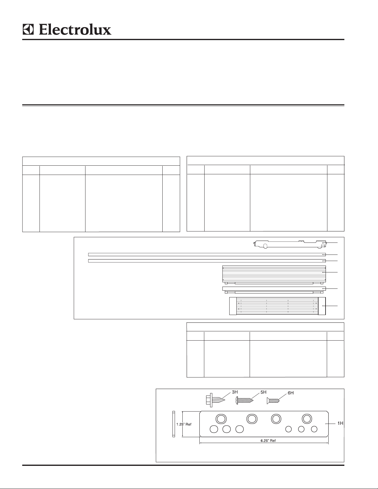
Single Trim Kit Components
INSTRUCTION SHEET
Parts Included in Kit TRIMKITEZ1 (Part# 808739901):
Kit for Frigidaire Models
Single Trim Kit 808739901
ITEM PART NUMBER DESCRIPTION QTY
1 808657301 Trim Side RH U19 1
2 808657302 Trim Side LH U19 1
3 808657602 Trim Top Short U19 Single 1
4 808667402 Trim Top Tall U19 Single 1
5 808709902 Kick Plate U19 Single 1
6 297337700 Carton, Packaging 1
7 A00350301 Hardware Pack Single U19 1
8 297276900 Leveler Assembly Support System 2
Single Trim Kit
Parts Included in Kit TRIMKITSS1 (Part# 808739902):
Kit for Electrolux Models
Single Trim Kit 808739902
ITEM PART NUMBER DESCRIPTION QTY
1 808657303 Trim Side RH U19 1
2 808657304 Trim Side LH U19 1
3 808657604 Trim Top Short U19 Single 1
4 808667404 Trim Top Tall U19 Single 1
5 808709904 Kick Plate U19 Sngle 1
6 297337700 Carton, Packaging 1
7 A00350301 Hardware Pack Single U19 1
8 297276900 Leveler Assembly Support System 2
Front View
8
1
2
4
3
5
NOTE: All Hardware Pack components mentioned
throughout this instruction sheet will have an “H”
after the item number.
Hardware Pack A00350301
Hardware Pack A00350301
ITEM PART NUMBER DESCRIPTION QTY
1H 297333900 Tie-Bar Hinge 1
3H 297236250 Screw 1/4-20 x .63 8
5H 050149 Screw TH #8-18 x .75 AB 6
6H 297142600 Screw FH #8-32 x .63 2
7H A00343901 Installation Instructions 1
©2013 Electrolux Home Products, Inc. Instruction Sheet A00343901 11.04.13
1.25”
Ref
1.25”
Ref
6.25” Ref
2.62” Ref
1H
2H
3H4H 5H6H
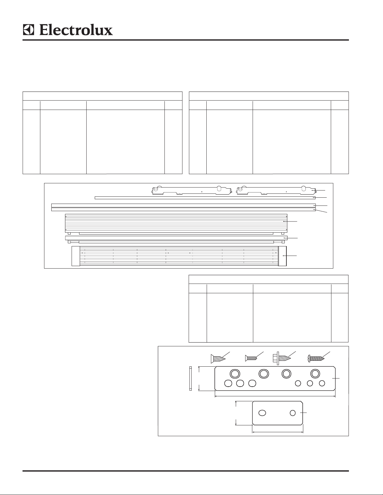
Dual Trim Kit Components
INSTRUCTION SHEET
Parts Included in Kit TRIMKITEZ2 (Part# 808743701):
Kit for Frigidaire Models
Double Trim Kit 808743701
ITEM PART NUMBER DESCRIPTION QTY
1 808674501 Center Trim U19 1
2 808676201 Trim Side RH U19 1
3 808676202 Trim Side LH U19 1
4 808657601 Trim Top Short U19 Dual 1
5 808667401 Trim Top Tall U19 Dual 1
6 808709901 Kick Plate U19 Dual 1
7 297337700 Carton, Packaging 1
8 A00350302 Hardware Pack Dual U19 1
9 297276900 Leveler Assembly Support System 4
Double Trim Kit
Front View
Parts Included in Kit TRIMKITSS2 (Part# 808743702):
Kit for Electrolux Models
Double Trim Kit 808743702
ITEM PART NUMBER DESCRIPTION QTY
1 808674501 Center Trim U19 1
2 808676203 Trim Side RH U19 1
3 808676204 Trim Side LH U19 1
4 808657603 Trim Top Short U19 Dual 1
5 808667403 Trim Top Tall U19 Dual 1
6 808709903 Kick Plate U19 Dual 1
7 297337700 Carton, Packaging 1
8 A00350302 Hardware Pack Dual U19 1
9 297276900 Leveler Assembly Support System 4
9
1
2
3
5
4
NOTE: All Hardware Pack components mentioned
throughout this instruction sheet will have an “H”
after the item number.
Hardware Pack A00350302
6
Hardware Pack A00350302
ITEM PART NUMBER DESCRIPTION QTY
1H 297333900 Tie-Bar Hinge 2
2H 297333901 Tie-Bar Back 1
3H 297236250 Screw 1/4-20 x .63 18
4H 297337000 Screw FH 1/4-20 x .63 4
5H 050149 Screw TH #8-18 x .75 AB 8
6H 297142600 Screw FH #8-32 x .63 2
7H A00343901 Installation Instructions 1
©2013 Electrolux Home Products, Inc. Instruction Sheet A00343901 11.04.13
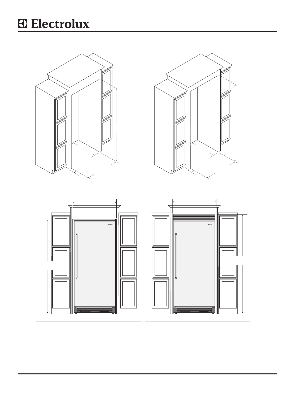
INSTRUCTION SHEET
TRIMKITEZ1 (Part# 808739901) & TRIMKITSS1 (Part# 808739902) Trim Kit Dimensions
75.09”
(1907 mm)
0.75”
(19.05 mm)
(min.)
25.25”
(641mm)
(min.)
(882 mm)
33.00 ± .032”
(838 ± .8mm)
34.74”
75.00 ± .06”
(1905 mm)
0.75”
(19.05 mm)
(min.)
34.74”
(882 mm)
79.00 ± .06”
(2006.5 ± 1.5mm)
25.25”
(641mm)
(min.)
33.00 ± .032”
(838 ± .8mm)
79.09”
(2009 mm)
©2013 Electrolux Home Products, Inc. Instruction Sheet A00343901 11.04.13
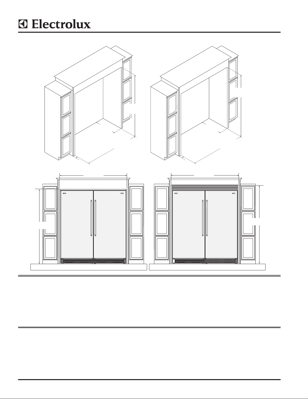
INSTRUCTION SHEET
67.12”
TRIMKITEZ2 (Part# 808743701) & TRIMKITSS2 (Part# 808743702) Trim Kit Dimensions
(2006.5 ± 1.5mm)
75.00 ± .06”
(1905 mm)
”
79.00 ± .06”
75.09”
(1907 mm)
0.75”
(19.05 mm)
(min.)
(641mm)
67.12”
(1705 mm)
25.25”
min.
66.00 ± .032
(1676.4 ± .8mm)
0.75”
(19.05 mm)
(min.)
25.25”
(641mm)
min.
(1705 mm)
66.00 ± .032
(1676.4 ± .8mm)
79.09”
(2009 mm)
Safety: Always wear safety glasses when using power tools.
Tools Needed:
• PhillipsTM Screwdriver • Adjustable Wrench to t 1-¼” • Step Ladder
• Flathead Screwdriver • 3/8” Socket Wrench • Tape Measure (min. 7” length)
• Safety Glasses • 7/16” Socket Wrench • Drill & 1/8” Bit
Before You Begin
• Be careful when unpacking components. Do not use sharp objects when removing packaging material. This may
scratch the surface of trim components.
• Use extreme care when handling the metal trim pieces. Corners are very sharp and easily damaged if dropped.
©2013 Electrolux Home Products, Inc. Instruction Sheet A00343901 11.04.13
INSTRUCTION SHEET
Setting Up The Trim And Grill Assembly
(Single and Dual Installations)
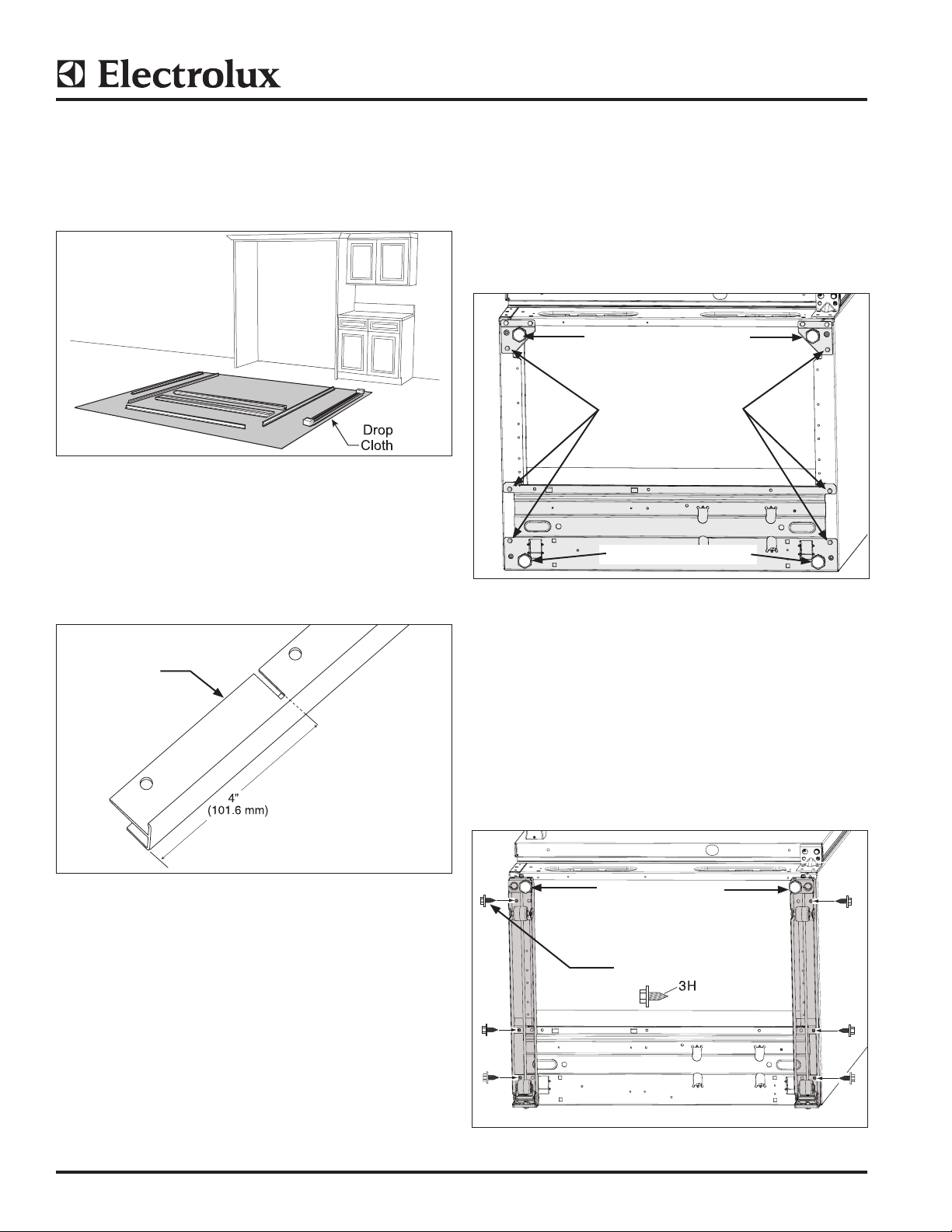
1. Lay the parts out on a cleared area face down. Be
sure to place a drop cloth over the floor to prevent
scratching trim kit and/or floor. (See Figure 1).
Figure 1
2. Cut 4” (101.6 mm) off the left and right Side Trim using
the slot as a guide to make the proper size for a 75”
(1905 mm) cut-out. (See Figure 2).
Leveling System Install
(Single and Dual Installations)
3. a. Lie unit on its back on packaging material or a
drop cloth to prevent damage.
b. Remove (3) screws from each side and discard.
(See Figure 3)
c. Remove and save both plastic leg levelers to use
in the next step.
Remove Leg Levelers
Remove And Discard
Screws
Remove Leg Levelers
NOTE: DO NOT cut the side trim if installing in a 79”
(2006 mm) opening.
Side Trim
Left and Right
Sides
Figure 2
Figure 3
4. a. Attach the current leg leveler to leveling system.
The leg leveler is a common part that will work
on both bottom sides of the unit. (See Figure 4).
b. Attach leg leveler with three (3) screws per side
using a 3/8 socket.
c. Re-install the leg levelers.
d. In order to provide clearance to access the rear
screw hole, adjust the rear roller up out of he
way. When finished, lower the rear roller back to
its initial position.
Install Leg Levelers
Install Screws
(3 per side)
Figure 4
©2013 Electrolux Home Products, Inc. Instruction Sheet A00343901 11.04.13
Trim Kit Installation
Installing Trim Kit Tie Bar
(Dual Installation Only)
NOTE: Leveling may be required to line up the holes
in steps “a” and “d”.
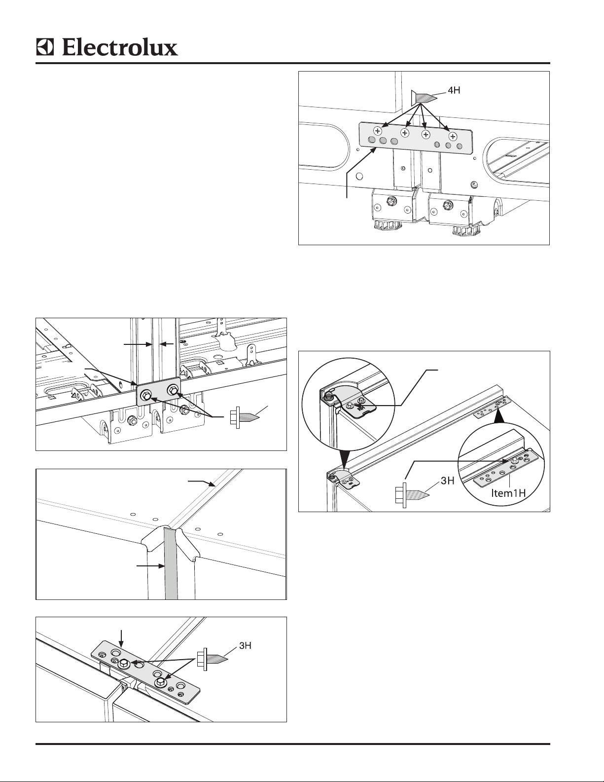
5. a. Tie units together by securing the mounting
bracket at the back of the units with a
3/8” socket. (See Figure 5).
b. Install center strip to insure the proper 3/8” gap
is maintained between units. (See Figure 6).
c. Tie units together with the common mounting
bracket at the front top with two screws in
the inner two screw holes by using a 3/8” socket.
(See Figure 7).
d. Tie units together with common mounting
bracket at the bottom front using #3 Phillips
driver. (See Figure 8).
3/8” Gap
INSTRUCTION SHEET
Item 1H
Figure 8
Trim Kit Installation (Single Unit Installation)
6. Remove outer screw from top hinge using a 3/8”
socket driver or wrench and save for later. Install
mounting bracket with one screw mounted to inside
hole using a 3/8” socket. (See Figure 9).
Item 2H
3/8” Center Strip
Item 1 Dual kit
Figure 5
3/8” Gap Between Units
Figure 6
Item 1H
Remove Screw
3
H
Figure 9
Side Trim Installation
(Single and Dual Installations)
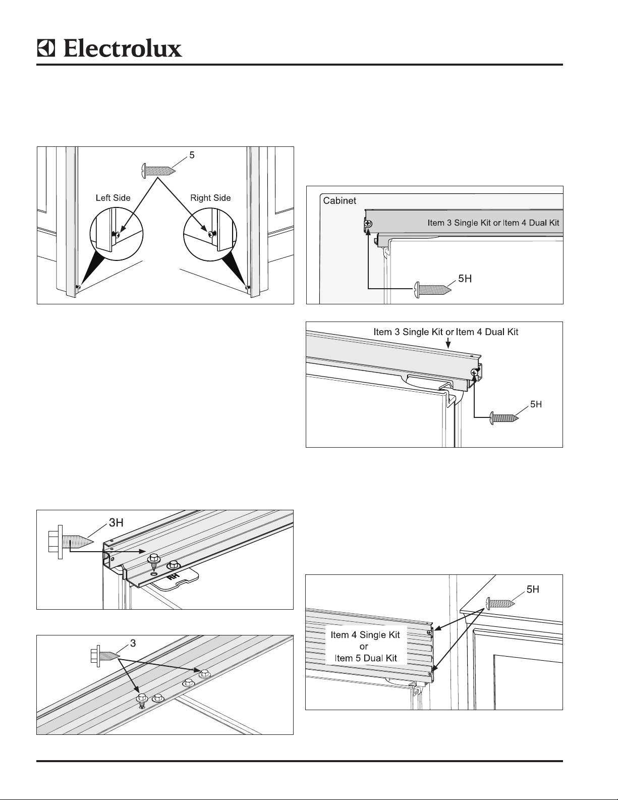
7. a. Position Left Hand Side Trim on cabinet trim with
bottom resting on the floor.
b. Drill the 1/8” (3mm) pilot hole.
c. Run screw in all the way and then back out.
Remove side trim for later install. (See Figure 10).
NOTE: Some cabinet substrates may require predrilling holes using a 1/8” (3 mm) diameter drill bit.
Figure 7.
©2013 Electrolux Home Products, Inc. Instruction Sheet A00343901 11.04.13
INSTRUCTION SHEET
8. a. Position Right Hand Side Trim on cabinet trim
with bottom resting on the floor.
b. Drill the 1/8” (3 mm) pilot hole.
c. Run screw in all the way and then back out.
Remove side trim for later install. (See Figure 10).
H
Figure 10
Top Trim Install
(Single and Dual Installations)
NOTE: Step ladder required for installing top
trim components.
10. 75” (1905 mm) High Opening With Top Trim
(Single and Dual Installations)
a. Slide units into place. Adjust height so top trim
height reaches 75.09” (1907 mm). Center units
in opening and level. (See Step 12 for leveling
instructions) (See Figures 13 and 14).
b. Drill 1/8” (3 mm) pilot holes and fasten screws
with a Phillips driver to kitchen cabinets.
Figure 13
9. a. Remove outer hinge screw common on both
sides for a dual installation, (for a single
installation this screw is removed in Step 6.
Align the top trim and attach with a 3/8” socket.
Repeat for opposite side. (See Figure 11).
b. (Dual installation only) Install outer screws on
common mounting bracket, align top trim
and attach with 3/8” socket. (See Figure 12).
Figure 11
H
Figure 14
11. 79” (2006 mm) High Opening With Louvered Top
Trim (Single and Dual Installations)
a. Slide units into place. Adjust height so top trim
height reaches 79.09” (2009 mm). Center units
in opening and level. (See Figure 15)
b. Drill 1/8” pilot holes and fasten two (2) screws
per side with a Phillips driver to kitchen cabinets.
Figure 12
Figure 15
©2013 Electrolux Home Products, Inc. Instruction Sheet A00343901 11.04.13
INSTRUCTION SHEET
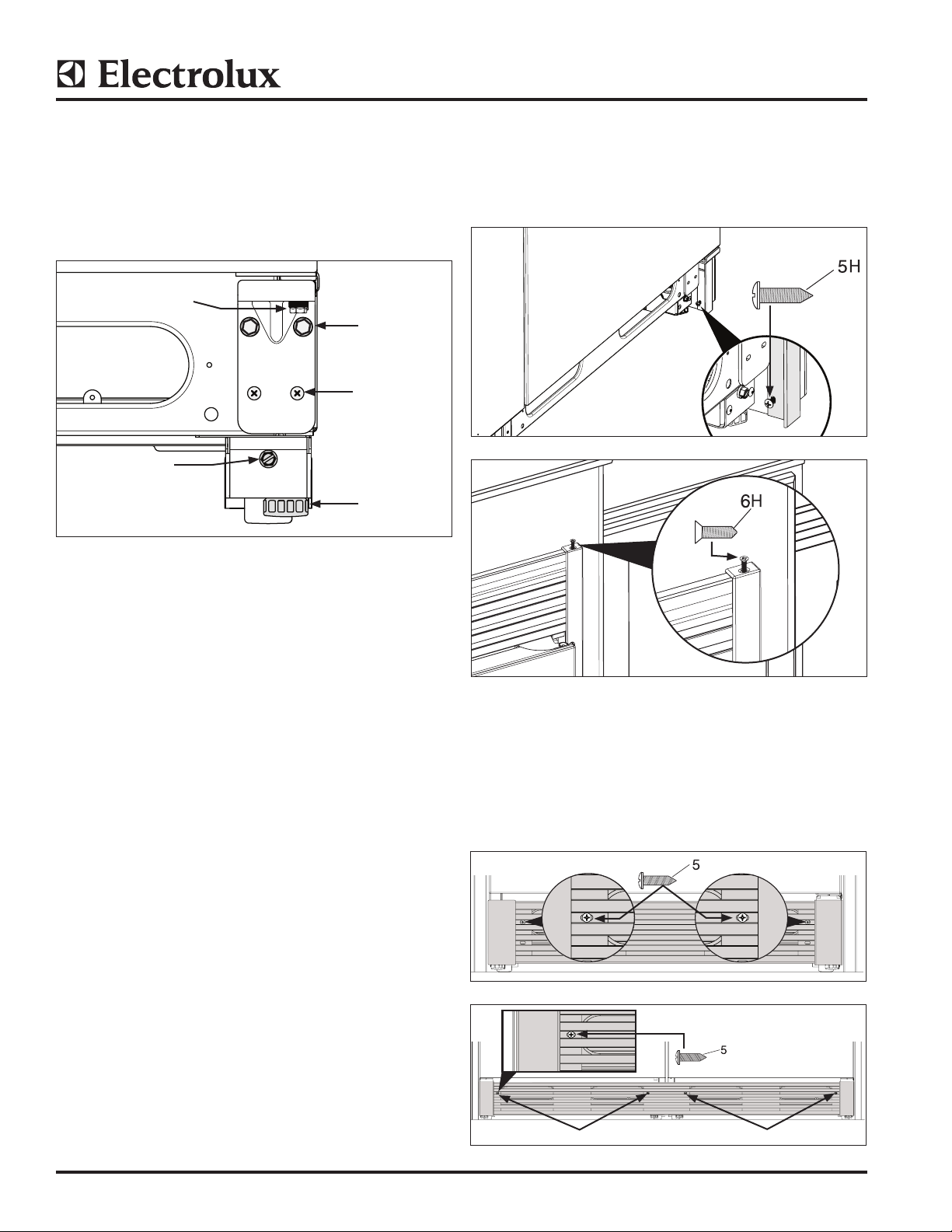
12. Trim Kit Leveling (See Figure 16)
(Single and Dual Installations)
a. To raise front of unit, turn leg leveler to left with
adjustable wrench to fit 1-¼” hex.
b. To raise back of unit, adjust bolt clockwise with
3/8” socket or flat head screwdriver.
To raise or lower door,
adjust 7/16” bolt.
3/8” Bolts
Phillips Head
Screws
To raise back of
unit, adjust bolt
clockwise.
Leg Leveler
Figure 16
14. Side Trim Attachment to Kitchen Cabinets
(Single and Dual Installations)
a. Fasten bottom of side trim with screw.
(See Figure 17).
b. Fasten screws to top trim. (See Figure 18).
Figure 17
13. Hinge Adjustment (See Figure 16)
(Single and Dual Installations)
a. The bottom hinge is designed to make final
minor adjustments for door to door and door to
cabinet alignment.
b. Hinge will move side to side 3/32” and raise
up 1/8”.
Use a 7/16” socket or open end wrench to raise or
lower the door.
Use a 3/8” socket and a Phillips screwdriver to loosen
bottom hinge. Shift door left or right, then retighten
screws and bolts.
Figure 18
15. Kick Plate Attachment
(Single Unit) Attach the kick plate to the cabinet
with two (2) screws. (See Figure 19).
(Dual Unit) Attach the kick plate to the cabinet
with four (4) screws. (See Figure 20).
Figure 19
Screws
Screws
Figure 20
©2013 Electrolux Home Products, Inc. Instruction Sheet A00343901 11.04.13
 Loading...