

Page 1
Doc. No: 560001 EG
Page:1 Ed.1" 08-2014
From ser. no.:
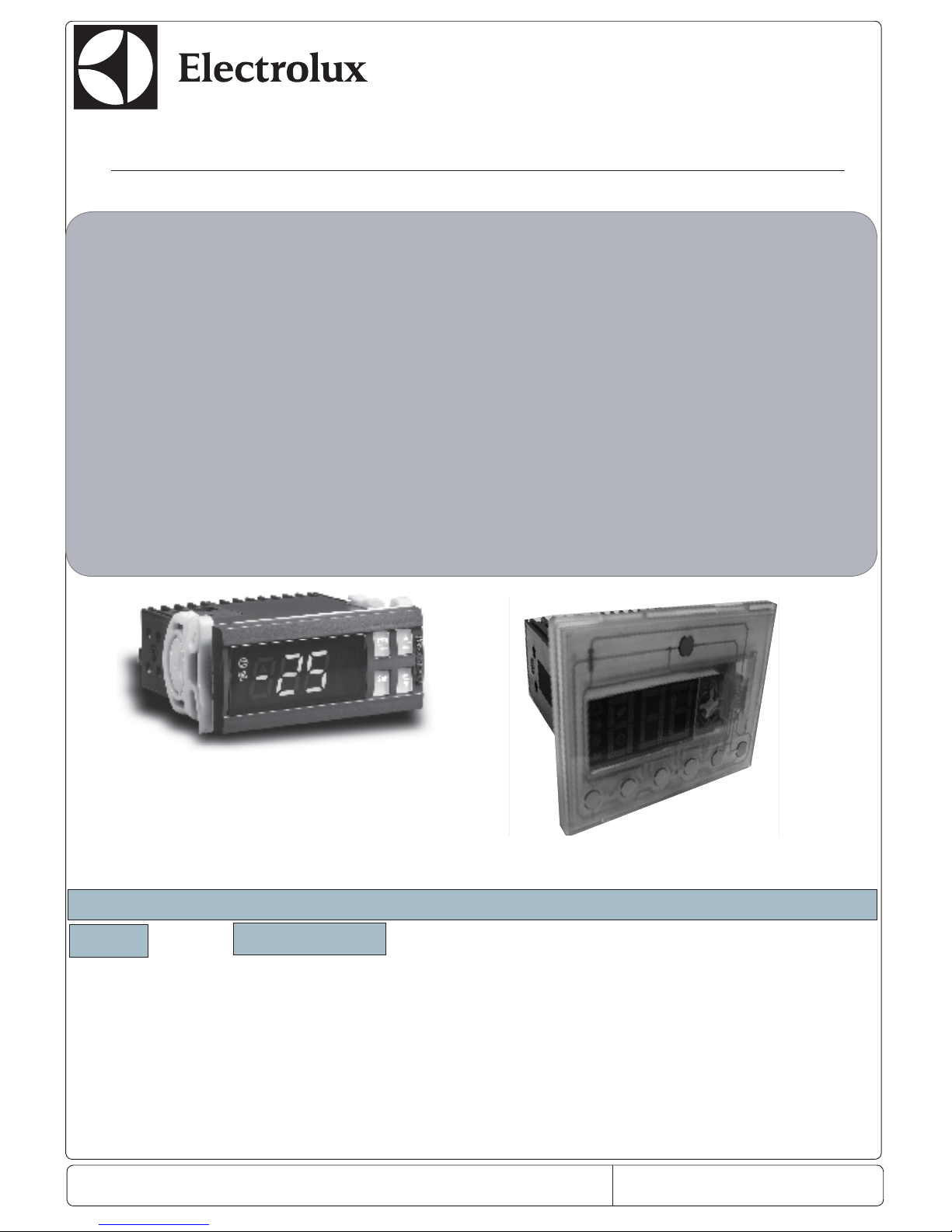
Quick reference manual
Thermoregulator
Management controller
Premium
&
Standard
Standard Model
Model for Ecostore Premium
CONTENTS
Page Description
2 Buttons
3 Icons
4 Programming
5 to 7 Parameters view
8 to 9 Service/ Temperature alarms
10 Defrost algorithm
11 to 14 Spare part code of controller
15 to 40 Parameter descriptions
Page 2
Doc. No.: 560001 EG
Page:2 Ed.1" 08-2014
From ser. no.:
GENERAL DESCRIPTION OF INSTRUMENT
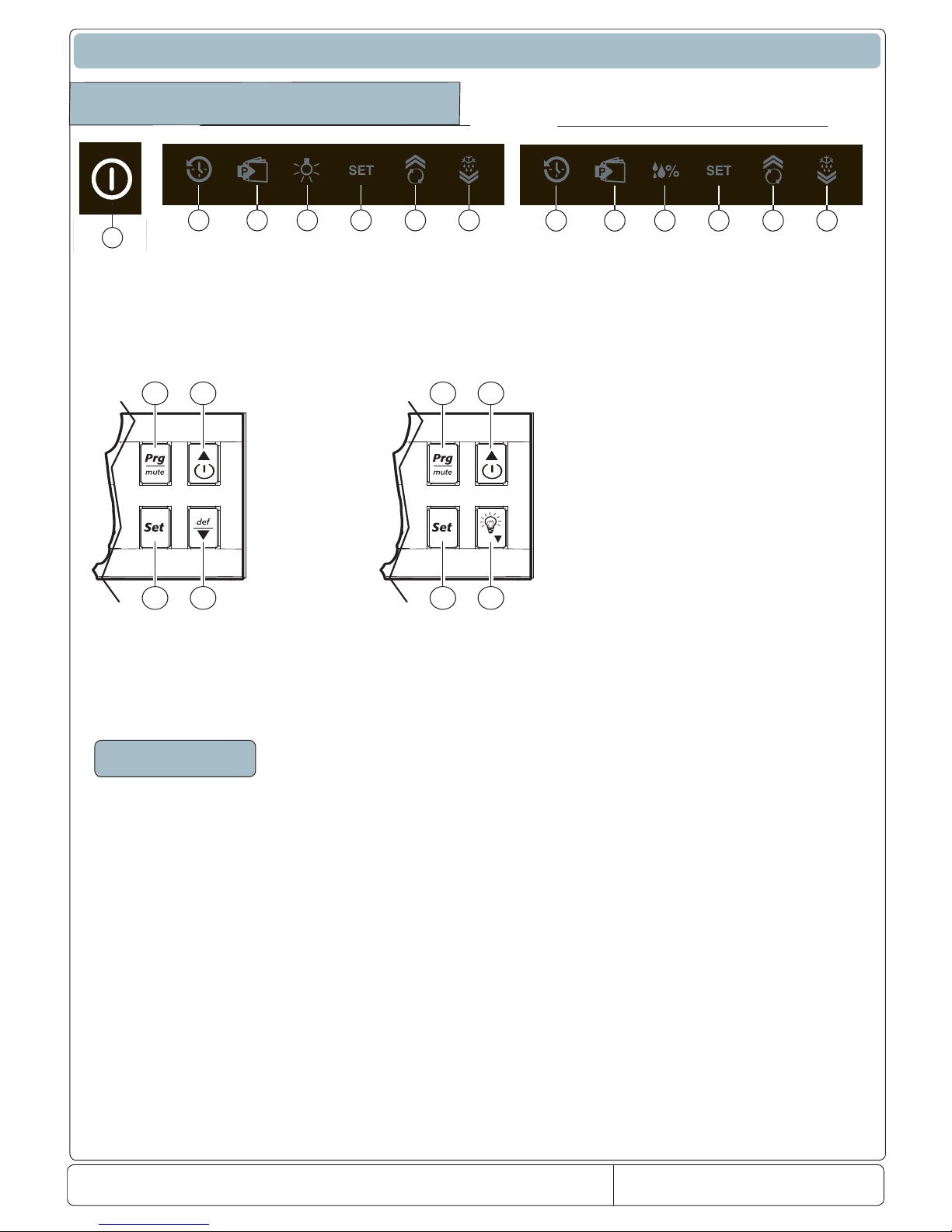
Description of buttons
1
2 3 4 5 6 7
PREMIUM
2 3 8 5 6 7
PREMIUM
Description
1. ON/OFF
2. History button
3. Programming confi rmation button
4. Light button
5. Temperatura/Programming button
6. Temperature decrease /Turbo cooling button
7. Temperature increase/Manual defrost button
8. Umidity button
3
6/1
75
3
6/1
45
Standard Control
Page 3
Doc. No: 560001 EG
Page:3 Ed.1" 08-2014
From ser. no.:
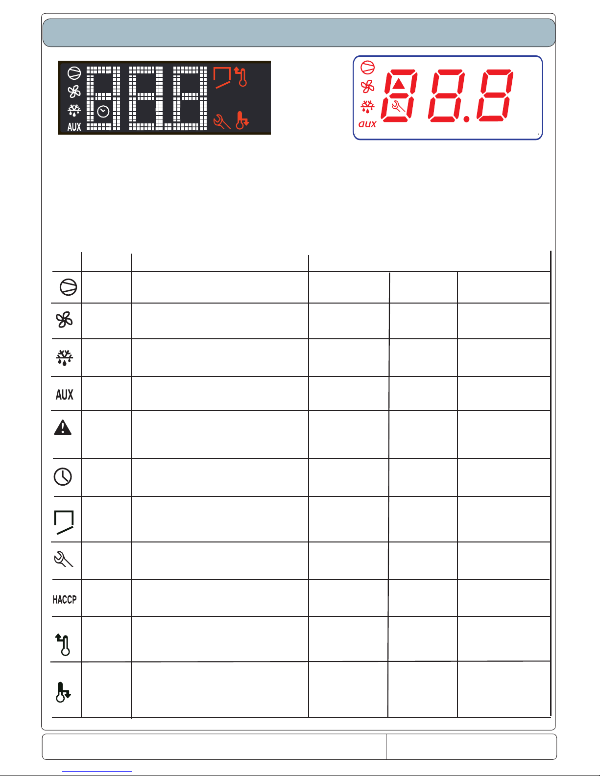
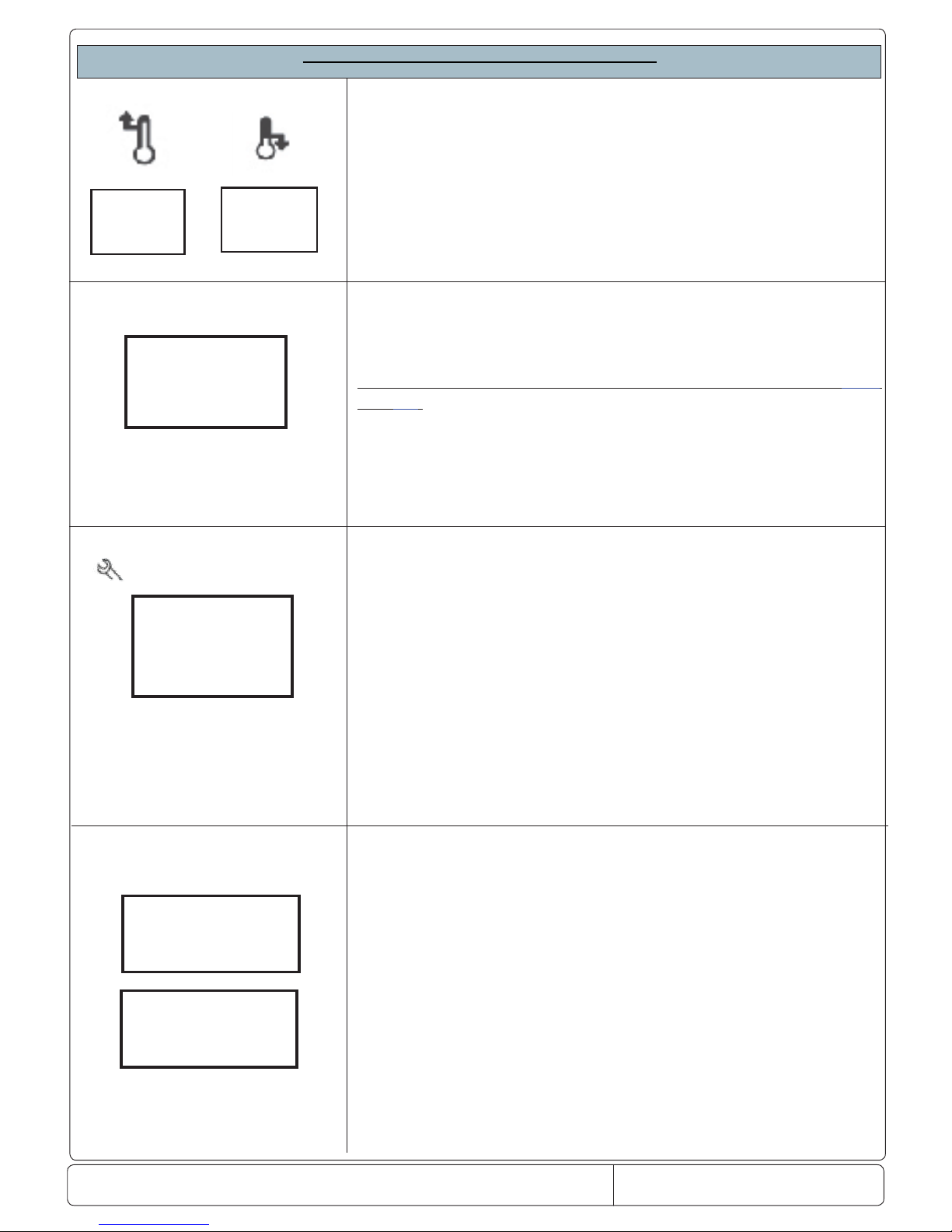
Description of Icons
Standard Control
Premium
ICON
FUNCTION
DESCRIPTION
NORMAL FUNCTIONING
ON OFF
BLINK
COMPRESSOR
ON when the compressor starts. Flashes when the activation
of the compressor is delayed by safety times.
Compressor on
Compressor o Awaiting activation
FAN
ON when the fan starts.Flashes when the activation of the fan is
prevented due to external disabling or procedures in progress.
Fan on
Fan o Awaiting activation
DEFROST
ON when the defrost is activated. Flashes when the activation of
the defrost is prevented due to external disabling or
procedures in progress.
Defrost in progress
Defrost not in progress Awaiting activation
AUX
Si accende all’attivazione dell’uscita ausiliaria selezionata come
AUX (LUCE)ON when the auxiliary output selected as
AUX (or LIGHT) is activated.
AUX auxiliary output active
AUX auxiliary output not
active
ALARM
ON following pre-activation of the delayed external digital input
alarm. Flashes in the event of alarms during normal operation
(e.g. high/low temperature) or in the event of alarms from an
immediate or delayed external digital input.
Delayed external alarm
(before the time ‘A7’ elapses)
No alarm present
Alarms in norm. operation
(e.g. High/low temperature)
or immediate or delayed alarm
from external digital input
CLOCK
On in case of consultation history temperature . History temperature History temperature not
consulting
DOOR
Blinking in case of door open/On in case of alarm door open Auxiliary exit Light ON Auxiliary exit Light ON
Door closed
Door open
Service
Flashes in the event of malfunctions, for example E2PROM errors or
probe faults
Programming , set temperature
No malfunction Malfunction (e.g. E2PROM error or
probe fault). Contact service
HACCP
ON if the HACCP function is enabled.Flashes when there are new
HACCP alarms stored (HA and/or HF alarm shown on the display)
HACCP function enabled HACCP function not
enabled
HACCP alarm saved
(HA and/or HF)
TEMPERATURE
ON in case of high Temperature Alarm High temperature
Alarm low temperatutre in
history
No alarm
No alarm
Actual alarm ( high temperature)
Actual alarm ( low temperature)
DISPLAY
ON in case Low temperature
Page 4
Doc. No.: 560001 EG
Page:4 Ed.1" 08-2014
From ser. no.:
INSTRUMENT PROGRAMMING
Operation parameters, completely modi able from front keypad. Access to these is protected by a password that prevents random changes or modi cations by
unauthorised persons.
Accessing parameters (confi guration):
1. press the PRG and SET buttons together for more than 5 seconds and the display will show "00", password required;
2. use the buttons or to scroll the numbers until displaying "11" (Password for accessing parameters);
3. con rming with SET, the rst modi able parameter will appear on the display.
Modifying parameters
After displaying the parameter, proceed as follows:
1. use the buttons or to scroll the parameters to the one to be modi ed. Scrolling is accompanied by lighting up of an icon on the display, representing the
parameter category. Alternatively, press the PRG button to display a menu of the categories or parameters for quickly accessing the family of parameters to be
changed;
2. scroll the menu with the buttons and and the codes of the various parameter categories (see "Summary of operation parameters") are displayed, together
with lighting up of the corresponding icon (if present);
3. on accessing the category, press SET to go straight to the rst parameter of the selected category (if no parameter is visible, pressing the SET button will
have no e ect);
4. it is possible to continue consulting the parameters or return to the categories menu with the PRG button;
5. press SET to display the value associated with the parameter;
6. increase or decrease the value respectively with the buttons and ;
7. press SET to temporarily save the new value and return to the display of the parameter. Repeat the procedure from step 1 or step 2;
8. if the parameter has subparameters, press SET to display the rst subparameter;
9. press the buttons or to view all the subparameters;
10. press SET to display the associated value;
11. increase or decrease the value respectively with the buttons or ;
12. press SET to temporarily save the new value and return to the display of the subparameter code;
13. press PRG to return to the display of the parent parameter.
Saving new values assigned to parameters
To permanently save the values of the modi ed parameters, press the PRG button for more than 5 seconds, thus exiting the parameter modi cation proce-
dure. It is possible to cancel all the parameter modi cations, temporarily stored in RAM, and return to "normal operation" by not pressing any button for 60 seconds,
thus allowing the parameter modi cation session to expire for TIMEOUT.
Attention: If the modi cation session expires for timeout, the parameters will not be not restored.
If the power to the instrument is switched o before pressing the PRG button, all changes made to the parameters and temporarily saved will be lost.
Page 5

Doc. No: 560001 EG
Page:5 Ed.1" 08-2014
From ser. no.:
Classifi cation of parameters
As well as being divided according to TYPE, the parameters are grouped into logical CATEGORIES identi ed by the initial symbols or letters.
Given below are the existing categories with respective letters.
Parameters Category Text Icon
/
Temperature probe management parameters
Pro
r
Temperature control parameters
CtL
c
Compressor safety time and activation parameters
CMP
d
Defrost management parameters
dEF
A
Alarm management parameters
ALM
F
Fan management parameters
fan
H
General conguration parameters (addresses, enabling, etc.…)
CnF
Default parameters
fo tinUegnaRnoitpircseDenoizircseDretemaraP
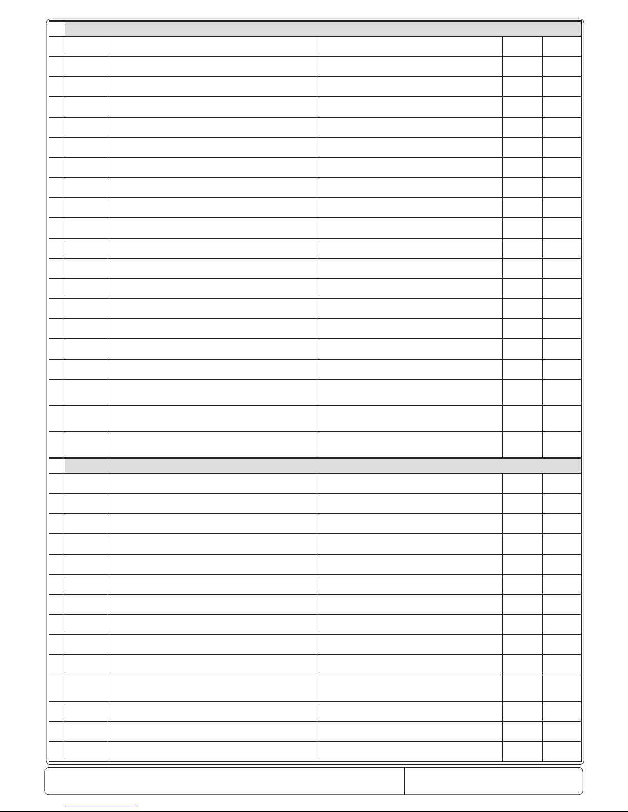
1
/
/2
Stabilità misura 51...4ytilibats tnemerusaeM
2
/3
Rallentamento visualizzazione sonda 51...0esnopser yalpsid eborP
3
/5
Selezione °C o°F galF1/0F° ro C° noitceleS
4
/6
Punto decimale galF1/0tniop lamiceD
5
/tl
Visualizzazione su terminale interno 7…1lanimret no yalpsiD
6
/A2
Configurazione sonda 2 4…02 eborp noitarugifnoC
7
/A3
Configurazione sonda 3 4…03 eborp noitarugifnoC
8
/c1
Calibrazione sonda CELLA 0.02..0.02- 1 eborp noitarbilaC
C/F (/10)
9
/c2
Calibrazione sonda 2 0.02..0.02- 2 eborp noitarbilaC
C/F (/10)
10
/c3
Calibrazione sonda 3 0.02..0.02- 3 eborp noitarbilaC
C/F (/10)
11
St
2r…1rtniop teStniop teS
C/
F
12
rd
Delta Regolatore
02…1.0atled lortnoC
C/ F
13
r1
Set minimo ammesso
2r...05-dewolla tniop tes muminiM
C/ F
14
r2
Set massimo ammesso
002…1rdewolla tniop tes mumixaM
C/ F
15
r5
Abilitazione monitoraggio temperatura
1...0 gnirotinom erutarepmet elbanE
C/ F
16
c0
Ritardo start compressore. ,ventole e aux zona neutra
all’accensione
niM51...0no rewop morf tuptuO yaleD
17
c1
Tempo minimo tra accensioni successive niM51…0no rewop neewteb yaleD
18
c2
Tempo minimo di On del compressore niM51...0emit FFO rosserpmoc muminiM
19
c4
Duty setting niM001…0gnittes ytuD
20
cc
Durata ciclo continuo sruoH51…0noitarud elcyc suounitnoC
21
c6
Esclusione allarme dopo ciclo continuo sruoH51…0elcyc suounitnoc retfa ssapyb mralA
PARAMETERS RELEVANT TO TEMPERATURE PROBE MANAGEMENT
PARAMETRI RELATIVI ALLA REGOLAZIONE DELLA TEMPERATURA\PARAMETERS RELEVANT TO TEMPERATURE CONTROL MANAGEMENT
PARAMETRI RELATIVI ALLA GESTIONE DEL COMPRESSORE\PARAMETERS RELEVANT TO COMPRESSOR MANAGEMENT
Page 6
Doc. No.: 560001 EG
Page:6 Ed.1" 08-2014
From ser. no.:
22
d
d0
Tipo di defrost galF4...0tsorfed fo epyT
23
dI
Intervallo tra i defrost sruoH052…0stsorfed neewteb lavretnI
24
dt1
Temperatura di fi ne defrost evap. End defrost temperature, evaporator -50…200
C/ F
25
dtP
002...0pots tinu ta erutarepmet tsorfed dnEoppurg id atamref a otnemanirbs enif id arutarepmeT
C/ F
26
dP1
Durata massima defrost evaporatore Maximum defrost duration, evaporator 1…250 Min
27
d3
Ritardo inserimento defrost niM052...0yaled trats tsorfeD
28
d4
Abilitazione defrost allo start up galFy/npu-trats no tsorfed elbanE
29
d5
Ritardo defrost allo start up niM052…0pu-trats no yaled tsorfeD
30
d6
Blocco display durante il defrost 2...0tsorfed gnirud dloh no yalpsiD
31
dd
Tempo di gocciolamento dopo il defrost niM51…0tsorfed retfa emit gnippirD
32
d8
Esclusione allarmi dopo il defrost sruoH51…0tsorfed retfa ssapyb mralA
33
d8d
Esclusione allarmi dopo aperture porta niM/sruoH052…0mrala gninepo rood no yaleD
34
d9
Priorità defrost su protezioni compressore Defrost priority over compressor protectors n/y Flag
35
dC
Base dei tempi per defrost galF1/0)s/m=1;m/h=0( tsorfed esab emiT
36
dC1
Base dei tempi per allarmi galF1/0)s/m=1;m/h=0( smrala esab emiT
37
d10
Running time del compressore sruoH052...0tsorfed rof emit gninnur rosserpmoC
38
d11
0.02..0.02-tsorfed rof erutarepmet emit gninnuRemit gninnur id arutarepmet id ailgoS
C/ F
39
dF0
Numero di ore del compressore attivo dopo il quale lo
sbrinamento deve essere attivato
NUM_COMP_ON number of hours the compressor is on
after which defrost must start
0...12 Hours
40
dF1
Numero di aperture porta dopo il quale il parametro DFO deve
decrementare
number of door openings after which dF0 must be
decreased
0...500 Units
41
dF2
Minuti da sottrarre al parametro DF0 per anticipare lo
sbrinamento
minutes to be subtracted to dF0 in order to anticipate
defrost
0...240 Min
42
A0
Differenziale allarmi e ventole 0.02…1.0laitnereffid )naf( mralA
C/ F
43
A1
Tipo di soglia AL e AH galf1/0mralA etulosbA ro evitaleR
44
AL
Soglia di allarme di bassa temperatura 002…05-dlohserht mrala erutarepmet woL
C/ F
45
AH
Soglia di allarme di alta temperatura 002…05-dlohserht mrala erutarepmet hgiH
C/ F
46
Ad
Ritardo segnalazione bassa e alta temperatura Low and high temperature signal delay 0…250 Min
47
A4
Confi gurazione ingresso digitale 1 galf51…0noitarugifnoc 1 tupni latigiD
48
A5
Confi gurazione ingresso digitale 2 galF51…0noitarugifnoc 2 tupni latigiD
49
A6
Blocco compressore da allarme esterno Stop compressor from external alarm 0…100 Min
50
A7
Ritardo rilevazione allarme esterno niM052…0yaled noitceted mrala lanretxE
51
A8
Abilitazione allarmi Ed1 ed Ed2 galF
0(off)-9(0n)
’2dE‘ dna ’1dE‘ smrala elbanE
52
A9
Segnale virtuale 2( usato per connttere la almpada a led)
Virtual input 2 configuration(Used in connection with
LED
_
Lam
p)
0…15 Flag
53
Ac
Allarme alta temperatura condensatore 002...0mrala erutarepmet resnednoc hgiH
C/ F
54
AE
Differenziale allarme alta temperatura condensatore High condenser temperature alarm differential 0.1...20
C/ F
55
Acd
Ritardo allarme alta temperatura condensatore High condenser temperature alarm delay 0…250 Min
PARAMETRI RELATIVI ALLA GESTIONE DELLO SBRINAMENTO\PARAMETERS RELEVANT TO DEFROST MANAGEMENT
PARAMETRI RELATIVI ALLA GESTIONE DEGLI ALLARMI\PARAMETERS RELEVANT TO ALARM MANAGEMENT
Page 7
Doc. No: 560001 EG
Page:7 Ed.1" 08-2014
From ser. no.:
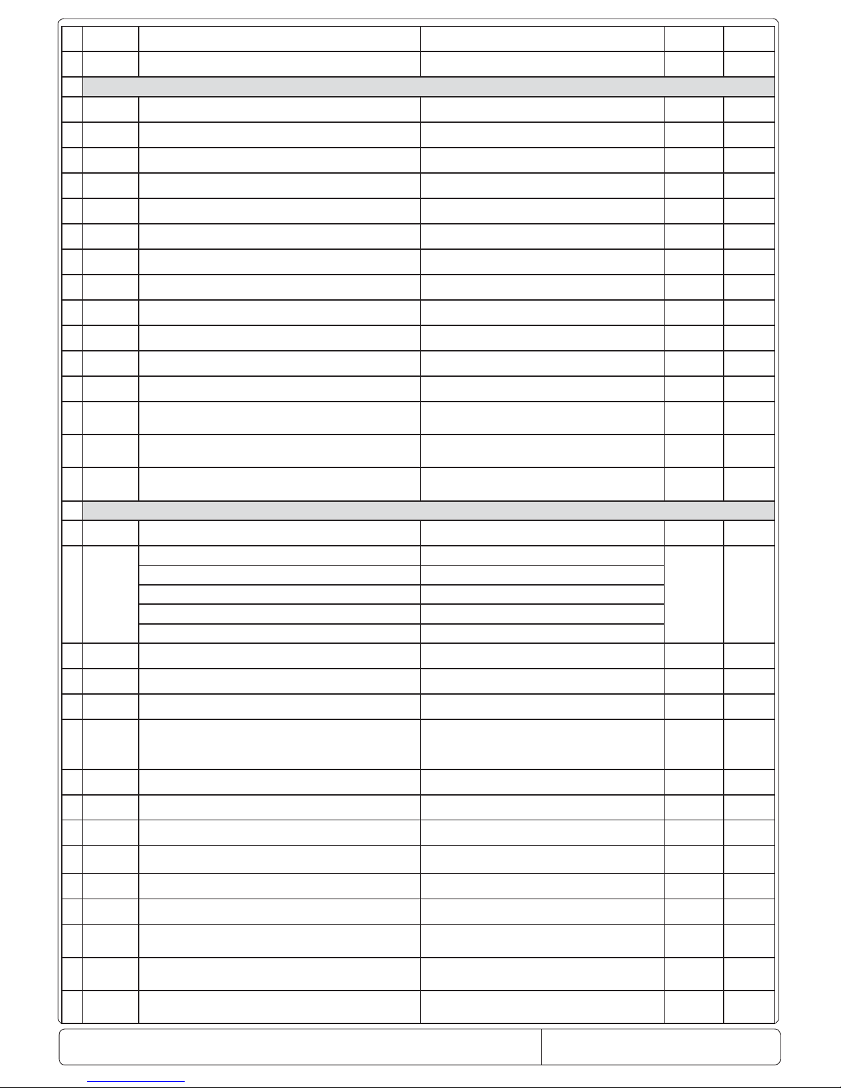
56
A
ACS
002+....05-tniopteS naelC mralAnaelC emralla rep erutarepmet id ailgoS
C/ F
57
ACd
Ritardo allarme alta temperatura condensatore Alarm Clean differential
C/ F
58
F0
Gestione ventilatori galF3...0tnemeganam naF
59
F1
Temperatura accensione ventilatore
002...05-erutarepmet pots naF
C/ F
60
F2
Ventilatore off con compressore off
galF1/0FFO rosserpmoc htiw FFO naF
61
F3
Ventilatore in sbrinamento
galF1/0tsorfed ni snaF
62
Fd
niM51…0gnippird retfa FFO naFotnemaloiccogs ol opod otneps erotalitneV
63
F10
2...0LVL_ytidimuHàtidimU
64
F11
ces006..0edom ytidimuh wol ni emit NO naFàtidimu assab ni osecca erotalitneV
65
F12
ces006..0edom ytidimuh wol ni emit FFO naFàtidimu assab ni otneps erotalitneV
66
F13
ces006..0edom ytidimuh muidem ni emit NO naFàtidimu aidem ni osecca erotalitneV
67
F14
ces006..0edom ytidimuh muidem ni emit FFO naFàtidimu aidem ni otneps erotalitneV
68
F15
ces006..0edom ytidimuh hgih ni emit NO naFàtidimu atla ni osecca erotalitneV
69
F16
ces006..0edom ytidimuh hgih ni emit FFO naFàtidimu atla ni otneps erotalitneV
70
F17
Differenziale del compressore in accensione con umidita bassa temperature differential for compressor ON in low hum. 0,1..20 sec
71
F18
Differenziale del compressore in accensione con umidita media
temperature differential for compressor ON in medium
hum.
0,1..20 sec
72
F19
Differenziale del compressore in accensione con umidita alta temperature differential for compressor ON in high hum. 0,1..20 sec
73
H0
702…0sserdda eciveDovitisopsid ozziridnI
4 yaler fo noitcnuF4 eler led otnemanoiznuF
)41 = evlavortcele
wolF()41 =alovlavorttele ossulF(
)51 = ecnatsiser emarF()51 =ecinoc aznetsiseR(
) 8 = thgil rood ssal
G()8 =ortev atrop ecuL(
) 2 = ecnatsiser epip niarD()2=asnednoc ociracs id aznetsiseR(
75
H2
galF6...0)6=N;1=Y( FFO/NO elbanE)6=N;1=Y ( FFO/NO otsat atilibasid/atilibA
76
H4
galF1/0rezzub elbasiDonilaciC atilibasiD
77
H6
552...0dapyek kcoLareitsat occolB
78
H7
Percentuale di umidità (H7=0 , disabilita controllo umidità F0=3)Attivazione Luce (H7=1) -Tipo di controllo : Versione Mass ( H7=2)
keyboard type: HUM% key (H7 = 0, enable humidity
management with F0=3) or LIGHT key (H7 = 1).
Controller t
yp
e: Mass version (H7 = 2
)
1...3
79
CCd
syaD999.......0syaD retnuoC naelCaizilup id inoig oiggetnoC
80
Cd
syaD999.......0syad naelCaizilup id inroiG
81
SAn
galF552.......0 rebmun smralA ecivreSitunevva ecivreS opit id imralla oremuN
82
SAr
galF1.......0naS teser retnuoc smralA ecivreSsmralA ecivreS ied erotatnoc led otnemarezzA
83
CAn
galF552.......0retnuoc mralA naelCteser omitlu’llad itunevva naelC imralla id oremuN
84
CAr
galF1.......0teser retnuoc mralA naelCnaelC id imralla ilged erotatnoc led otnemarezzA
85
4r1
Spazio tra il differnziale corrente e il flusso della temperatura della
elettrovalvola
Gap between current differential and flow electro-valve
tem
p
erature differential
0,1..20
C/ F
86
4r2
Abilita/disabilita la resistenza cornice mobile con la referenza
della tem
p
eratura impostata
Parameter (temperature) enabling/disabling frame
resistance with reference to chosen cell set
p
oint
-20..20
C/ F
87
4r3
Ritardo per la resistenza di scarico( il tempo deve includere la
durata del defrost
)
Delay for drain pipe switch-off (the value must include the
defrost duration
)
0...60 min
74
PARAMETRI GENERALI DI CONFIGURAZIONE
PARAMETRI RELATIVI ALLA GESTIONE DEL VENTILATORE EVAPORATORE\PARAMETERS RELEVANT TO EVAPORATOR FAN MANAGEMENT
H1
0...16 Flag
Page 8
Doc. No.: 560001 EG
Page:8 Ed.1" 08-2014
From ser. no.:
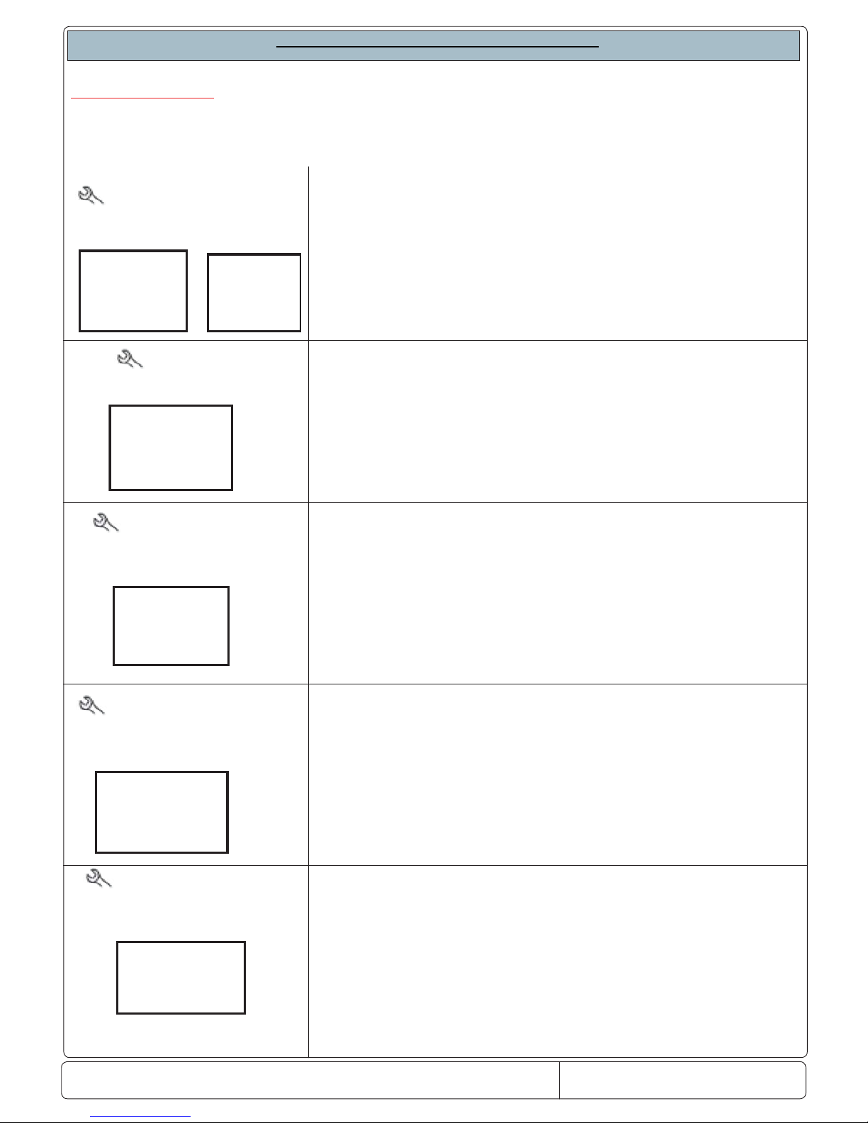
In case of faulty thermostatting probe, the display shows the message rE alternating with E0 (compartment probe S1). The appliance still
works and compressor activation and/or deactivation is time managed (15 min. ON and 15 min. OFF). The alarm condition is automatically reset as soon as compartment probe operation is restored.
In case of faulty room probe, the display shows the message E1 (room
probe S2). The alarm condition is automatically reset as soon as compartment probe operation is restored.
The service alarm signalling icon fl ashes whereas the controller buzzer
is deactivated
The service alarm signalling icon fl ashes whereas the controller buz-
zer is deactivated. In case of faulty condenser probe (if installed on
the machine), the display alternately shows the message SEr/E2. The
alarm condition is automatically reset as soon as compartment probe
operation is restored.
Clean alarm: when the condenser is very dirty on the display will
appear the label
CLn; this alarm dosen’t stop the cycle but only
advises the customer to clean the condenser. The
CLn alarm
appears only after 90 days to work of compressor and when the
temperature of the condenser and ambient is over to delta of the
parameter
ACS
The alarm disapears when the temperature decrease from parameter
ACd.( differential) or pressing the button Prg.
With the LED lamp disconnected, the display will show the message
ce in sequence of temperature.
This happens when the lamp is disconnected or damaged.
In case of no lamp connection, the controller does not diagnose any fault.
The alarm disappears when the lamp is reconnected.
Parameter to be confi gured for lamp A9=9
THERMOSTATTING PRO-
BE FAULT ALARM
ROOM PROBE
FAULT ALARM
CONDENSER PROBE
FAULT ALARM (IF PRESENT)
CLEAN ALARM (ACTIVA-
TABLE IF CONDENSER PRO-
BE IS PRESENT)
LED LIGHT CE ALARM
(in Premium models only)
SERVICE ALARMS AND SIGNALLING
SERVICE ALARMS
ALL THE SERVICE ALARMS GENERATED FOR APPLIANCE FAULTS ARE SIGNALLED ON THE DISPLAY THROUGH
THE ASSISTANCE REQUEST ICON
E0
rE
E1
E2
CLn
00cn
Page 9
Doc. No: 560001 EG
Page:9 Ed.1" 08-2014
From ser. no.:
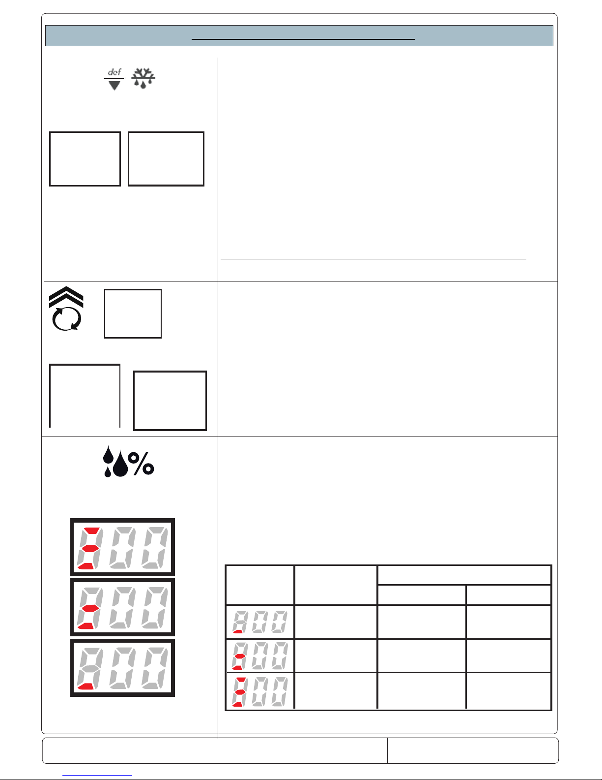
To manually activate a defrost cycle it is necessary to keep the temperature decrease button pressed for at least 3 seconds.
The display shows the message dFb/defrost
start for a few seconds
and the icon signalling activation of the defrost cycle lights up.
Defrost can be manually stopped by pressing the DEF/decrease temperature button again for at least 3 seconds. The display shows the
message dFE/defrost
end.
Defrost in the range models is carried out following the algorithm values: 1) parameter dF0, associating the actual hours of compressor
operation, 2) parameter dF1, number of door openings, where parameter dF0 must be reduced ,3)parameter dF2, minutes to be add to
parameter dF1 from subtracted to parameter dF0,to anticipate defrost .
Parameter dl remains active if these values are not respected.
In case of activation of continuous cycle, by pressing the temperature
decrease button for more than 5 seconds the display will show the
message ccb, at the same time as the temperature the message tc
will appear, meaning that “turbo cooling” has been activated. The cycle
will end for time, by parameter CC, or for temperature by parameter
AL, or by pressing the button again.
The humidity value is activated by pressing the corresponding button.
Three modes can be activated: low, medium, high % .F0= 3
The function activates the evaporator fans following the logic of low,
medium and high humidity % to be obtained in the compartment.
The parameters functioning in this are:
MANUAL DEFROST
ACTIVATION OF “TURBO COOLING” CONTINUOUS CYCLE
ccb
ACTIVATION OF HUMIDITY
CYCLE
SERVICE ALARMS AND SIGNALLING
DFb
dFE
ccE
tC
Selection
Correspondence
Low humidity
Medium humidity
High humidity
Fans always ON
Fans always ON
Fans always ON
F11= Fans ON
F12= Fans Off
F13= Fans ON
F14= Fans Off
F15= Fans ON
F16= Fans Off
Compressor OFF
Compressor ON
Evaporator fans functionality
Page 10
Doc. No.: 560001 EG
Page:10 Ed.1" 08-2014
From ser. no.:
dor
When the time set on parameter d8d is expired, the alarm dor
appear on the display, following from buzzer signaling and the red
light on blinking , (premium model only).
The alarm disappear when the door is closed.
The buzzer is off pressing the icon on display.
If the alarm is On with the door closed, this is due to :
- door not aligned
- control panel not aligned
- sensor broken
The calibration of infrared sensor is of 9 mm: over this distance
the sensor not more close the contact and the alarm will be always present.
0
0
EE
0
EF
When one of the other alarms apper on the display , check the
parameter list.
If the parameters setted are not kept in memory replace the
instrument.
EPROM ALARM
SERVICE ALARMS AND SIGNALLING
HI
LO
TEMPERATURE ALARM
TEMPERATURE ALARM
"SER"
SEr
The icon light up and audible alarm sound when the compartement
temperature exceeds the set maximun value. The alarm ceases
when the temperature returns to Set point.
A Parameter AL and AH determine the threshold of alarm of hight
or lower temperature.
Another parameter as Ad determine the delay of alarm .
When the temperature return to set point, and the icon stay again
ON , press the button PRG or directly on icon.
When the temperature of condenser is over of delta parameter AC
with a delay time to
Acd , the alarm “SEr” appears on the display
and the compressor if
stopped.
The alarm can be resetted pressing togheter the buttons PRG
and
UP and the delay Acd will be re setted. The compressor will
be ON only if the temperature reaches the value of AC-AE and the
time of value ( C1 ( compressor delay at power on) will expired. If
the alarm “
Ser” appears again check if the condenser fan works or
not.
DOOR OPEN
Page 11
Doc. No: 560001 EG
Page:11 Ed.1" 08-2014
From ser. no.:
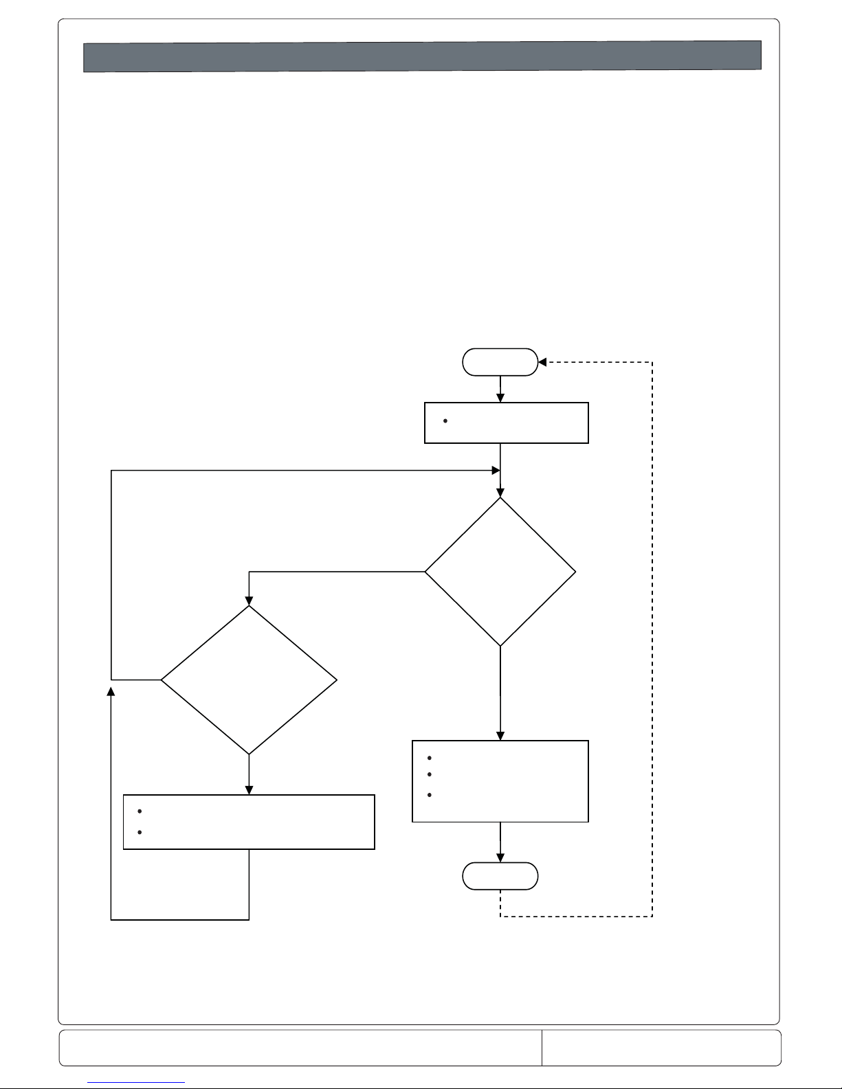
Algoritmo defrost/defrost algorithm Ecostore ONLY
Defrost
Defrost management has in principle the same features of the current FW: however, as the evaporator probe is
not present, defrost will be managed by counting working hours of the compressor and will end for timeout.
A programmed defrost will be done every defined number (parameter dF0) of working hours.
In addition, the algorithm will count the number of openings of the door as well. The aim is to anticipate of a
number of minutes (dF2) the programmed defrost with reference to the total number of openings of the d
oor.
Every time the programmed defrost is done, the total on-time hours of compressor and the number of door
openings will be reset. Proper parameters will be employed in order to manage this algorithm.
In order to do this, consider flux diagram of Figure 3.4. For instance, t_on_cmpr is the variable counting on-time
hours of compressor starting from last defrost, whereas n_open_door is the number of openings of the door.
t_on_cmpr is reset after each defrost, while n_open_door is reset every time it reaches dF1 value.
Figure
3.4: ux diagram for defrost algorithm.
START
t_on_cmpr
≥
defrost_cycle
do defrost
t_on_cmpr = 0
n_open_door = 0
END
n_open_door
≥
dF1
defrost_cycle = defrost_cycle - dF2
n_open_door = 0
?
YES
NON
O
YES
?
defrost_cycle = dF0
Page 12
Doc. No.: 560001 EG
Page:12 Ed.1" 08-2014
From ser. no.:
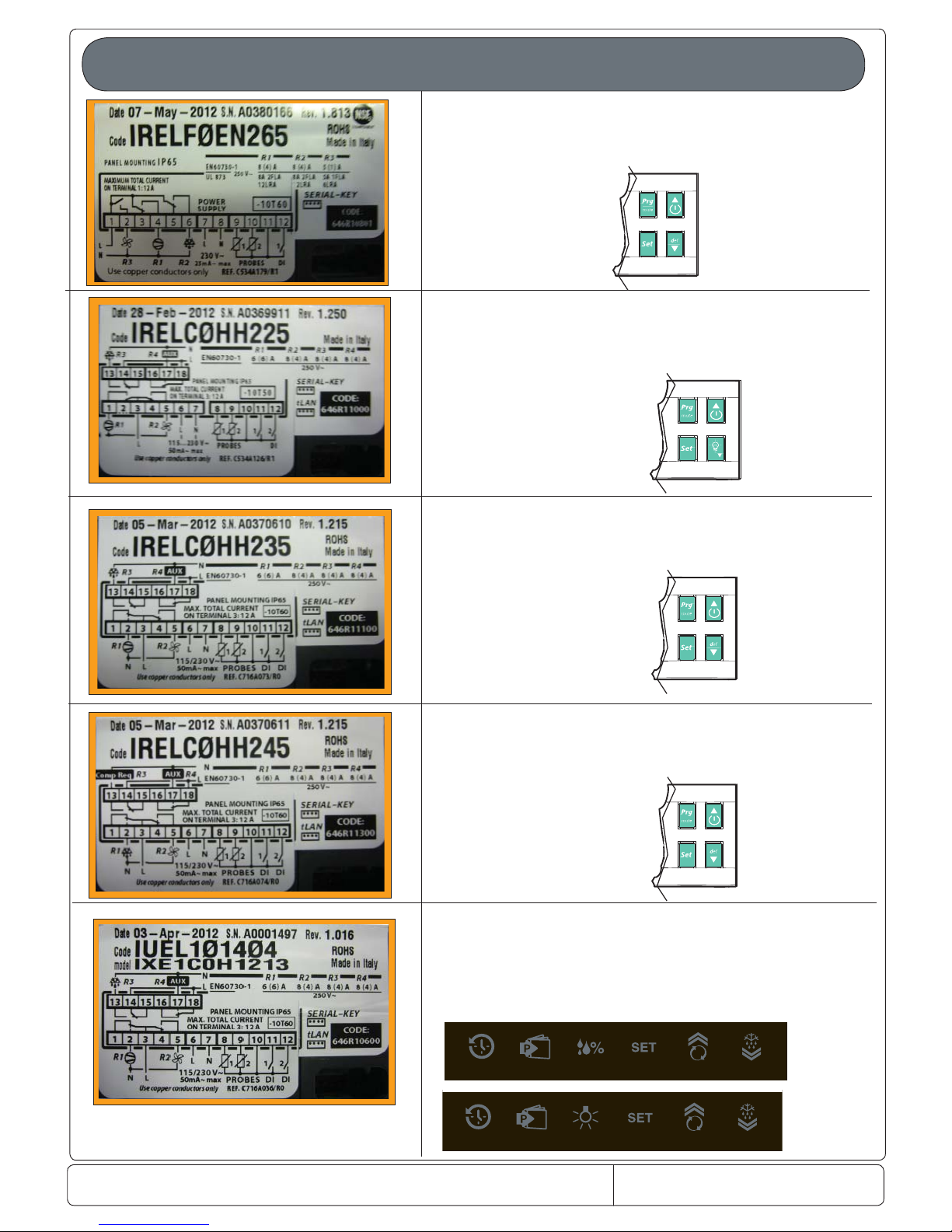
Main termoregulator and where used
Factory code 646R10802
SPC = 093328
used on Mass and Gab freezer and refrigerated
3 relay ( 8A -8A-5A)
Factory code 646R11001
SPC = 093329
used on Mass and Gab glass door freezer and refrigerated
4 relay ( 16A -8A-8A-8A)
Factory code 646R11101
SPC = 093434
used on Mass dual temp MASTER freezer and refrigerated
4 relay ( 16A-8A -8A-8A)
Factory code 646R11301
SPC = 093438
used on Mass dual temp SLAVE freezer and refrigerated
4 relay ( 16A-8A -8A-8A)
Factory code 646R10602
SPC = 093437
used on Premium all and as Master on dual temperature
4 relay ( 16A-8A -8A-8A)
Page 13
Doc. No: 560001 EG
Page:13 Ed.1" 08-2014
From ser. no.:
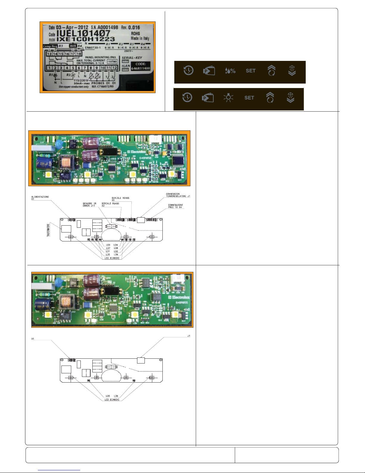
Factory code 646R11401
SPC = 093439
used on Premium as Slave on dual temperature
4 relay ( 16A-8A -8A-8A)
Factory code 648R05000
SPC = 093389
used on Premium dual doors
and Super premium
Factory code 648R05500
SPC = 093388
used on Premium one doors
and half doors
Power
Termoregulator
Page 14
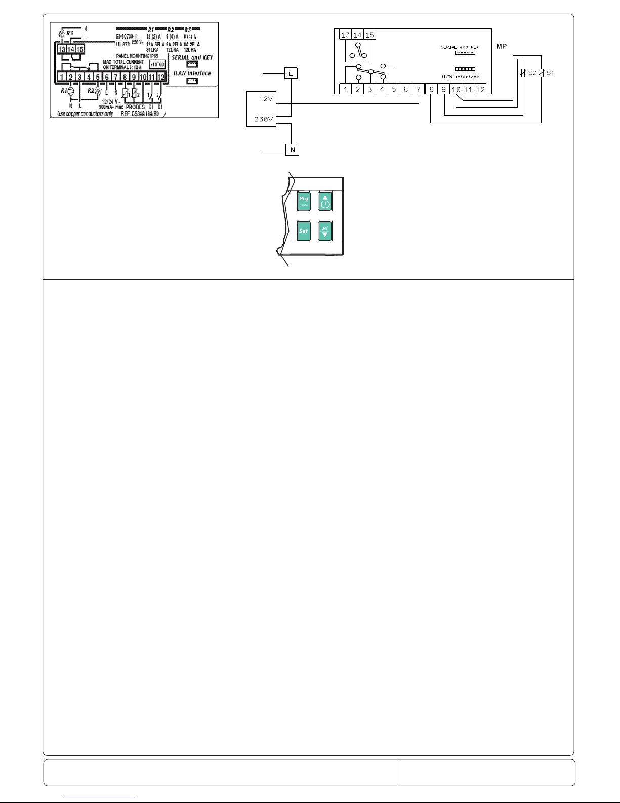
Doc. No: 560001 EG
Page:14 Ed.1" 08-2014
From ser. no.:
Factory code 646R11500
SPC = 0TH303
used on all Cabinets and couters all
range asia sb line with power supply to
12V
Page 15
Doc. No.: 560001 EG
Page:15 Ed.1" 08-2014
From ser. no.:
ENGLISH
7.1 Temperature probe management parameters
Code Parameter Models UOM Type Min Max Def.
Pw Password MSYF - C 0 200 22
/2 Measurement stability MSYF - C 1 15 4
/3 Probe display response MSYF - C 0 15 0
/4 Virtual probe MSYF - C 0 100 0
/5 Select °C or °F MSYF ag C 0 1 0
/6 Decimal point MSYF ag C 0 1 0
/tI Display on internal terminal MSYF - C 1 7 1
/tE Display on external terminal MSYF - C 0 6 0
/P S elect type of probe MSYF - C 0 2 0
/A2 Con guration of probe 2 (S2) YF - C 0 4 2
MS - C 0 4 0
/A3 Con guration of probe 3 (S3, DI 1) MSYF - C 0 4 0
/A4 Con guration of probe 4 (S4, DI 2) MSYF - C 0 4 0
/A5 Con guration of probe 5 (S5, DI 3) MSYF - C 0 4 0
/c1 Calibration of probe 1 MSYF °C/°F C -20 20 0.0
/c2 Calibration of probe 2 MSYF °C/°F C -20 20 0.0
/c3 Calibration of probe 3 MSYF °C/°F C -20 20 0.0
/c4 Calibration of probe 4 MSYF °C/°F C -20 20 0.0
/c5 Calibration of probe 5 MSYF °C/°F C -20 20 0.0
Tab. 7.a
Note: par. /A5 and /c5 refer to instruments with 5 relays (ir33DIN, powercompact and MasterCella).
‘/2’: Measurement stability
De nes the coe cient used to stabilise the temperature reading. Low values assigned to this parameter allow a prompt response of
the sensor to temperature variations, but the reading becomes more sensitive to disturbance. High values slow down the response, but
guarantee greater immunity to disturbance, that is, a more stable and more precise reading. The parameter acts on the temperature
readings, ltering the minimum variations, and at the same time considers the average of the readings. Default: ‘/2’=4.
/3: Probe display response
This parameter is used to set the update rate for the temperature display. The temperature shown on the display tends to follow rapid
deviations away from the set point very slowly, and vice-versa, moves very quickly in the event where the temperature displayed is
nearing the set point. If the control temperature exceeds the high or low temperature thresholds (and an AL or AH alarm is activated), or
if the maximum number of ltering steps (255) is exceeded (see the Timeout column in Table 7.b), the ltering would immediately be
bypassed and the temperature displayed would be the temperature e ectively measured, until all the alarms are reset. The parameter
only a ects the temperature displayed, and not the temperature used for the control functions.
Important:
• the control temperature actually measured di ers from the value displayed, and therefore the outputs may not be activated with
reference to the latter temperature value.
• if the probe displayed is a product probe, with temperature values higher than the set point, the probe display rate algorithm will
be faster for decreases in the temperature and slower for increases;
• if the probe displayed is an evaporator or condenser probe, the display rate algorithm always refers to the set point and thus may
have speci c e ects (fast when the evap. probe reading increases and slow when it decreases; fast when the condenser probe
reading decreases and slow when it increases);
• the parameter /3 acts on the temperature displayed by the instrument, if /tE=0 (no probe displayed by the repeater display); if
the repeater display is con gured (/tE <> 0), the parameter /3 will act on the temperature displayed by the repeater.
Example: in the case of “bottle coolers”, typically used in supermarkets, when the doors are opened frequently, due to the greater
thermal inertia of the liquids compared to the air (and the fact that the probe is positioned in the air and not directly on the products),
the instrument measures a temperature that is higher than e ective temperature of the soft drinks, thus displaying a quite “unrealistic”
temperature. Setting the parameter /3 to a value other than 0, any abrupt variations in temperature are “ ltered” on the display,
showing a temperature trend that is “closer” to the actual trend of the product temperature. The following table shows the possible
values of ‘/3’ and the corresponding display delayed update values (Tdel).
Value of par. /3 Display delay (Tdel) Timeout
0 Disabled 0
1 5 s 21 min
2 10 s 42 min
3 15 s 64 min
4 20 s 85 min
5 25 s 106 min
6 30 s 127 min
7 40 s 170 min
8 50 s 212 min
9 60 s 255 min
10 75 s 319 min
11 90 s 382 min
12 105 s 446 min
13 120 s 510 min
14 150 s 637 min
15 180 s 765 min
Tab. 7.b
Default: ‘/3’=0 => Function disabled.
/4: Probe average (virtual probe)
This parameter is used to choose whether to control the temperature based solely on the room probe reading, or alternatively
whether to refer to the “weighted” average of the room probe S1 and probe 2 (S2, see the parameter ‘/A2’). This parameter is
useful in special applications.
7. DESCRIPTION OF THE OPERATING PARAMETERS
Page 16

Doc. No.: 560001 EG
Page:16 Ed.1" 08-2014
From ser. no.:
ENGLISH
Example: if the room probe is in intake mode, and probe 2 in outlet mode, control can be performed based on the weighted
average of the 2 values read.
The formula used is: probe average (Virtual probe) = [S1 x (100 - P) + (S2 x P)] / 100 where:
S1 = room probe; S2 = probe 2; P = value of the parameter /4.
Virtual probe:
• /4=0 control is performed using the room probe - this is the typical situation;
• /4=100 control is performed in reference to the values read by probe 2;
• /4=50 control refers to a “virtual” probe, calculated based on the average between the room probe and probe 2. With values
above 50, probe 2 has a greater weight in the calculation, vice-versa for values below 50.
Important: in the event of faults or if probe 2 is not enabled, the instrument uses the room probe only. If the fault is on the room
probe, the “Control probe” error is signalled.
Default: /4=0 => control on room probe.
/5: Select °C or °F
De nes the unit of measure (degrees Centigrade or degrees Fahrenheit) shown on the display.
/5=0 to operate in degrees Centigrade.
/5=1 to operate in degrees Fahrenheit.
Default: /5=0 => operation in degrees centigrade.
/6: Decimal point
Used to enable or disable the display of the temperature with resolution to the tenth of a degree between -20 and + 20.
Note: the exclusion of the decimal point is active only with reference to the display of the reading on the main and remote
displays, while the parameters are always set to the tenth of a degree.
‘/6’=0 the readings are displayed to the tenth of a degree, between -20 and +20 °C;
‘/6’=1 all the readings are displayed without the tenths of a degree.
Default: /6 = 0 = > decimal point displayed.
/tI: Probe displayed on instrument
For selecting the probe to be displayed by the instrument.
/tI=1 => virtual probe
/tI=2 => probe 1
/tI=3 => probe 2
/tI=4 => probe 3
/tI=5 => probe 4
/tI=6 => probe 5
/tI=7 => set point
Note:
• control is always based on the virtual control probe;
• if the probe to be displayed has not been enabled, the display will show the message ‘___’.
Default: /tI=1 => Virtual probe.
/tE: Probe displayed on external terminal
Selects the probe to be displayed on the remote terminal.
/tE=0 => remote terminal not present
/tE=1 => virtual probe;
/tE=2 => probe 1;
/tE=3 => probe 2;
/tE=4 => probe 3;
/tE=5 => probe 4;
/tE=6 => probe 5.
Important:
Control is always based on the virtual control probe;
If the probe to be displayed has not been enabled, the display will show the message ‘___’;
If the probe to be displayed is faulty, the display will show the message ‘___’;
If the terminal is not present, the display will remain completely dark.
Default: /tE=0 => Remote terminal not present.
/P: Select type of probe
Used to select the type of probe used for the measurements.
/P=0 => NTC standard with range -50T90 °C
/P=1 => NTC with extended range -40T150 °C
/P=2 => PTC standard with range -50T150°C
For correct readings from the PTC probes, the hardware must be prepared to accept PTC readings (as well as NTC).
Note: all models in the ir33 range manage NTC probes with extended range (models HT).
Default: ‘/P’=0 => NTC standard with range -50T90 °C
Available on all models tted with NTC inputs.
Page 17
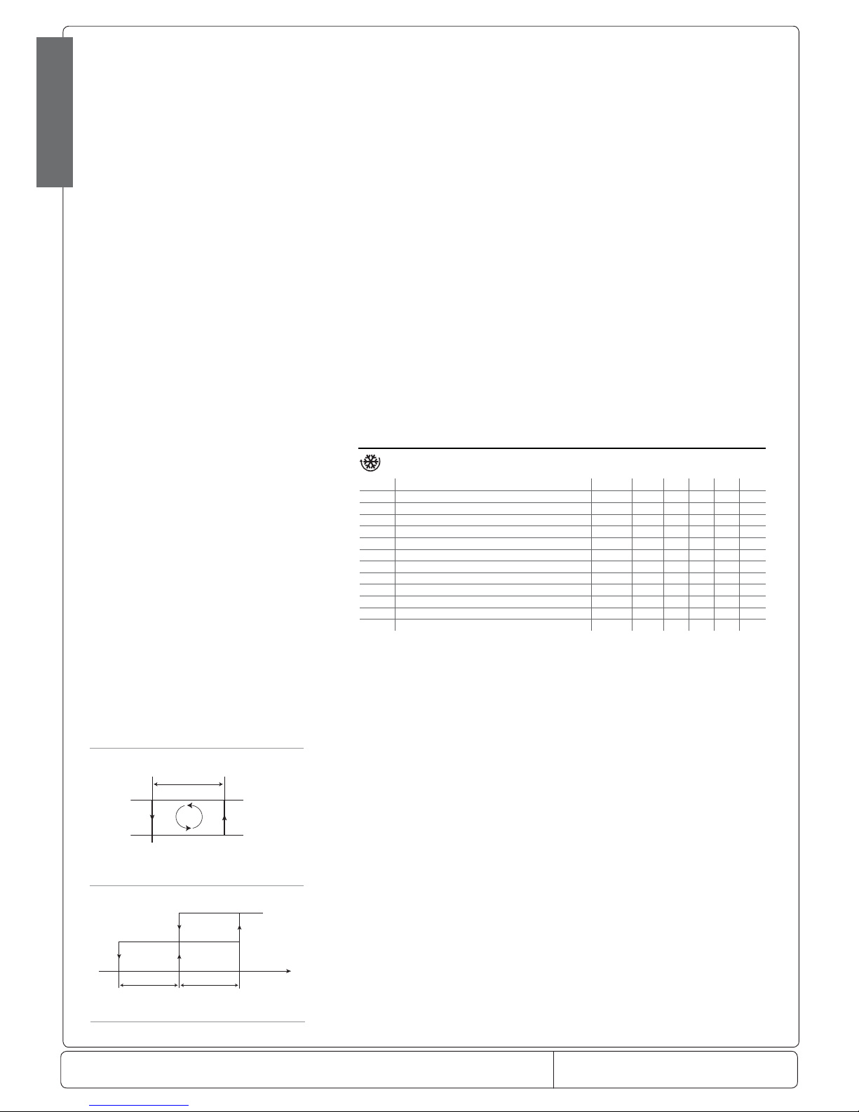
Doc. No.: 560001 EG
Page:17 Ed.1" 08-2014
From ser. no.:
rd
Set Point
OFF
ON
DIRECT Freddo
attuatore
D
St
rd/2 rd /2
Sonda virtuale
Direct
ENGLISH
Fig. 7.b
Fig. 7.a
/A2: Con guration of probe 2
Used to con gure the operating mode of probe 2.
/A2= 0 => probe 2 absent
/A2= 1 => product probe (used for display only)
/A2= 2 => defrost probe
/A2= 3 => condenser probe
/A2 = 4 => antifreeze probe
In any case, probe 2 is used for calculating the virtual control probe.
Default: /A2= 2 => defrost probe; /A2= 0 on models M and S => probe 2 absent.
/A3: Con guration of probe 3
As above, but relating to probe 3.
Important note: the input is enabled for use with a probe only if the parameter corresponding to digital input A4 is set to 0.
Default: /A3= 0 => Probe 3/Digital input absent.
/C1: Calibration or o set for probe 1
/C2: Calibration or o set for probe 2
/C3: Calibration or o set for probe 3
These parameters are used to correct the temperature measured by the probes, using an o set: the value assigned to these
parameters is in fact added to (positive value) or subtracted from (negative value) the temperature measured by the probes. The
temperature value is corrected by the o set before checking if the reading is out-of-range.
Example: to decrease the temperature measured by probe 1 by 2.3 degrees, set /C1= -2.3. The calibration or o set can be set
from -20 to +20.
Warning: if the probe is disabled, the display shows ‘___’. If the probe is faulty, the display shows the corresponding error code.
When displaying the parameter, pressing SET shows the value of the corresponding probe already corrected with the o set, while
pressing SET a second time displays the abbreviated code.
Default: /C1=/C2=/C3=/C4=/C5=0 no o set.
7.2 Temperature control parameters
Code Parameter Model UOM Type Min Max Def.
St Temperature set point MSYF °C/°F F r1 r2 0.0
rd Control delta -SYF °C/°F F 0.1 20 2.0
rn Dead band -SYF °C/°F C 0.0 60 4.0
rr Reverse di erential for control with dead band -SYF °C/°F C 0.1 20 2.0
r1 Minimum set point allowed MSYF °C/°F C -50 r2 -50
r2 Maximum set point allowed MSYF °C/°F C r1 200 60
r3 Operating mode -SYF ag C 0 2 0
r4 Automatic night-time set point variation MSYF °C/°F C -20 20 3.0
r5 Enable temperature monitoring MSYF ag C 0 1 0
rt Temperature monitoring interval MSYF hours F 0 999 rH Maximum temperature read MSYF °C/°F F - - rL Minimum temperature read MSYF °C/°F F - -
Tab. 7.c
St: set point
Establishes the set point value used by the controller. D efault: St=0.0.
rd: Control delta
Establishes the value of the di erential, or hysteresis, used for temperature control. Low values guarantee an ambient temperature
that deviates only slightly from the set point, but involves frequent starts and stops of the main actuator (normally the compressor).
In any case, the compressor can be protected by suitably setting the parameters that limit the number of
activations/hour and the minimum OFF time (see the C parameters).
Note: if control with two compressor steps has been selected (‘H1, H5’=12, 13), the di erential ‘rd’ is divided between the two
steps.
Default: rd =2
rn: Dead band
Establishes the value of the dead band, when the auxiliary output is selected as heating, in control with dead band mode. The
di erential is in the centre of the dead band.
Page 18
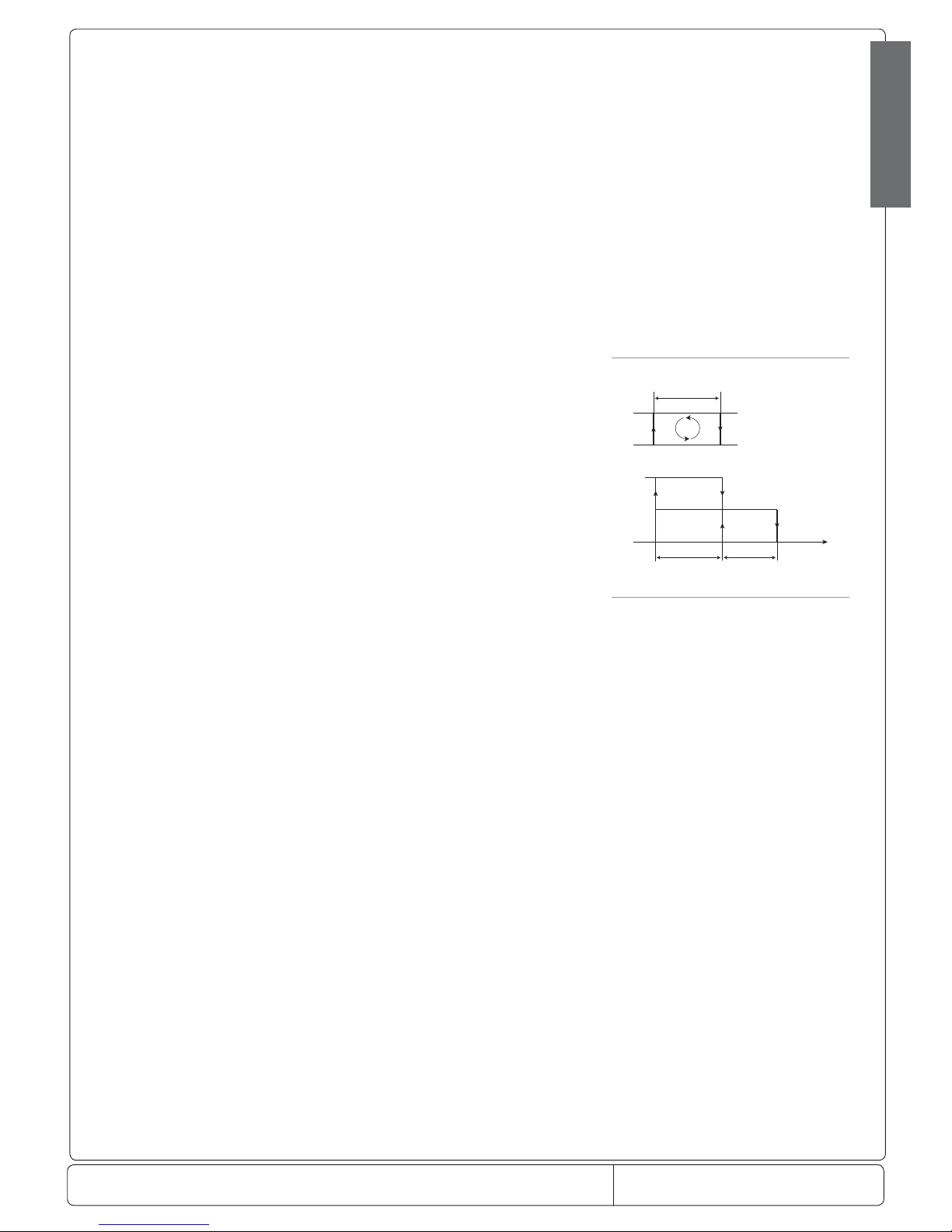
Doc. No.: 560001 EG
Page:18 Ed.1" 08-2014
From ser. no.:
rd
OFF
ON
REVERSE Caldo
attuatore
R
St
rd/2 rd/2
Sonda
virtuale
Reverse
Fig. 7.c
ENGLISH
Note:
• the step associated with the aux 1 or 2 output is only associated with the protection timer c0, while the step associated with the
compressor (in both direct and reverse operation) is associated with the timers c0, c1, c2, c3. As a result, the steps may be active
at the same time due to the protectors associated with the compressor step (minimum on time), as well as the unit defrost
status;
• if the curtain switch function is enabled (‘A4, A5, A9’=7), the controller modi es the set point when the contact closes, adding
or subtracting the value of parameter ‘r4’; the new value is used for all functions relating to the set point (e.g. relative high and
low temperature alarms, dead band, etc.). When ‘r4’=3.0 (preset value) the set point is increased by 3 degrees compared to the
value used with the curtain open.
Default: ‘rn’=4.
rr: Reverse di erential for control with dead band
Establishes the value of the di erential used in reverse temperature control, when the auxiliary output is selected as heating, in
control with dead band mode. Default: ‘rr’=2.
Note: no protection times are featured for the reverse output.
r1: minimum set point allowed
Determines the minimum value that can be set for the set point. Using this parameter prevents the user from setting a set point
lower than the value indicated by r1. Default: r1=-50.
r2: maximum set point allowed
Determines the maximum value that can be set for the set point. Using this parameter prevents the user from setting a set point
higher than the value indicated by r2. Default: r2 = +60.
r3: operating mode
ir33 can work as a thermostat and defrost controller for static units at normal temperature (r3=0), as a simple thermostat in Direct
operation (r3=1), or as simple thermostat in Reverse-cycle operation (r3=2).
r3=0 Direct thermostat with defrost control (cooling);
r3=1 Direct thermostat (cooling);
r3=2 Reverse-cycle thermostat (heating).
Also see the description of parameters A4, A5, A9.
Note: with r3=1 and r3=2, the defrosts are always disabled.
A digital input set for direct/reverse-cycle control with parameter r3 has priority over the operating mode. The gure to the side
shows reverse control with two compressor steps.
Default: r3=0=> Direct thermostat operation with defrost control.
r4:Automatic variation of the set point in night-time operation
This parameter is part of the group for control of the curtain switch, together with A4, A5 and A9,
programmable for con guring the digital inputs. When the curtain is closed, and consequently, the digital input connected to the
curtain switch is closed, the controller automatically increases the set point by the value assigned to r4 in direct mode (cooling),
and automatically decreases the set point by the value assigned to r4, in reverse mode (heating).
Important: if the value of r4 is negative, the controller with the curtain switch closed will decrease the set point, in direct mode
(cooling), and increase the set point in reverse mode (heating).
Default: r4=3.0..
r5: Enable minimum and maximum temperature monitoring.
r5=0 disabled
r5=1 enabled
Default: r5=0
rt: E ective interval for monitoring the maximum and minimum temperature.
rH: Maximum temperature measured in the interval rt.
rL: Minimum temperature measured in the interval rt
All these parameters are used by the instruments to record the minimum and maximum temperature measured by the room
probe in a period of up to 999 hours (over 41 days). To enable this function, proceed as follows:
• set r5=1; select rt;
• press SET to display for how many hours the minimum and maximum temperature have been recorded (if the function has just
been enabled, rt=0);
• to start recording the temperatures again, press q for more than 5 seconds when displaying the hours (the message rES
indicates that the value has been reset).
The instrument resets the number of hours and restarts the monitoring process;
• to display the maximum temperature measured by the probe, read the value associated with rH, while to display the minimum
temperature measured by the probe, read the value associated with rL..
Important:
• after the maximum time of 999 hours, the monitoring of the minimum and maximum temperature continues, while the time
value remains xed at 999.
Page 19

Doc. No.: 560001 EG
Page:19 Ed.1" 08-2014
From ser. no.:
accensione strumento
power ON
ON
ON
OFF
ON
OFF
OFF
C0
richiesta di intervento
insertion request
compressore
compressors
ON
ON
OFF
OFF
C1
richiesta inserimento
insertion request
compressore
compressors
ON
ON
OFF
OFF
C2
richiesta inserimento
insertion request
compressore
compressors
ON
ON
OFF
OFF
C3
richiesta inserimento
insertion request
compressore
compressors
ON
OFF
C4
compressore
compressors
OFF = 15 min.
Fig. 7.d
Fig. 7.e
Fig. 7.f
Fig. 7.g
Fig. 7.h
ENGLISH
7.3 Compressor management parameters
Code Parametro Models U.M. Type Min Max Def.
c0 Compressor, fan and AUX start delay on power up in dead zone -SYF min C 0 15 0
c1 Minimum time between successive starts -SYF min C 0 15 0
c2 Minimum compressor OFF time -SYF min C 0 15 0
c3 Minimum compressor ON time -SYF min C 0 15 0
c4 Duty setting -SYF min C 0 100 0
cc Continuous cycle duration -SYF hours C 0 15 0
c6 Alarm bypass after continuous cycle -SYF h/min C 0 250 2
c7 Maximum pump down time -SYF s C 0 900 0
c8 Comp. start delay after open PD valve -SYF s C 0 60 5
c9 Enable autostart function in PD -SYF ag C 0 1 0
c10 Select pump down by time or pressure -SYF ag C 0 1 0
c11 Second compressor delay -SYF s C 0 250 4
Tab. 7.d
c0: Compressor and fan start delay (if ‘FAN’ relay present) on start-up
When the controller is switched on, the compressor and the evaporator fans and the auxiliary relay in control with dead band (H1 or
H5=11) start after a delay (in minutes) equal to the value set for this parameter, in order to protect the compressor against repeated
power-ups in the event of frequent power drops. Default: c0=0 => no minimum delay is set.
Example: setting c0=6 forces the compressor to wait 6 minutes before starting from when power returns. In the event of systems
with more than one compressor, the parameter c0 can also be used to avoid simultaneous starts of a series of units. Simply set
a di erent value of c0 for each compressor.
Note: the second compressor step, for the aux 1 or 2 output (‘H1 or H5’=12, 13), is
associated with the timers ‘c0’, ‘c1’, ‘c2’, ‘c3’.
c1: Minimum time between two successive starts of the compressor
Sets the minimum time (in minutes) that must elapse between two starts of the compressor, irrespective of the temperature and the
set point. Setting this parameter limits the number of starts per hour.
Default: c’=0 => no minimum time is set between two starts.
Example: if the maximum number of activations/hour allowed is 10, simply set c1=6 to ensure that this limit is respected. Note:
the second compressor step, for the aux 1 or 2 output (‘H1 or H5’=12, 13), is associated with the timers ‘c0’, ‘c1’, ‘c2’, ‘c3’.
c2: Minimum compressor OFF time
SSets the minimum time (in minutes) for the compressor to remain OFF. The compressor is not started again until the minimum
time selected (c2) has elapsed from when it last stopped.
Note: this parameter is useful to ensure the balancing of the pressure after the compressor stops for systems with hermetic and
capillary compressors. The second compressor step, for the aux 1 or 2 output (‘H1 or H5’=12, 13), is associated with the timers
‘c0’,‘c1’,‘c2’,‘c3’.
c3: Minimum compressor ON time
Sets the minimum running time for the compressor. The compressor is not stopped until it has been ON for at least the minimum
time selected (c3).
Note: the second compressor step, for the aux 1 or 2 output (‘H1 or H5’=12, 13), is associated with the timers
‘c0’,‘c1’,‘c2’,‘c3’.
Default: c3=0 => no minimum running time is set.
c4: Duty setting
If the virtual control probe fault alarm occurs (see parameter ‘/4’), this parameter is used to ensure the operation of the compressor until the fault is resolved.
Default: c4=0 => compressor always O in the event of a virtual control probe error.
Important: In the event of errors on probe 2, the virtual probe corresponds to the room probe (probe 1) and consequently the
Duty Setting is not activated.
In practice, as the compressor is no longer able to operate based according to the temperature (due to the probe fault), it is made
to run cyclically with an operating time (ON time) equal to the value assigned to parameter c4 (in minutes) and a xed OFF time
of 15 minutes.
There are two values of c4 that cause special behaviour:
c4=0, in the event of faults involving the virtual control probe, the compressor is always OFF;
c4=100, the compressor is always ON, that is, the 15 minute OFF time is always ignored.
Special situations:
• if the virtual control probe error occurs while the compressor is OFF, it remains OFF for 15 minutes, and is then started
(respecting the times set for parameters c1 and c2) and remains ON for a time equal to c4, Duty Setting. This special operation is
signalled by the LED that ashes during the compressor OFF period, and remains on steady when the compressor is operating.
The fans continue to operate according the set parameters (see F parameters). If the duty setting requires the immediate shutdown of the compressor for a non-speci ed time (c4= 0), this is done without observing the compressor protection times.
• if the virtual control probe error occurs while the compressor is ON, it remains ON for the time c4, and then is stopped (without
observing the minimum ON time, if set for parameter c3) and remains OFF for 15 minutes (the LED ashes in this phase).
After this, cyclical operation starts, with an operating time equal to the value of c4.
Warning: If the virtual probe error disappears, the unit returns to normal operation.
Note: if control with two compressor steps is selected (with or without rotation, ‘H1 or H5’= 12 or 13), the duty setting acts on
both steps.
Page 20

Doc. No.: 560001 EG
Page:20 Ed.1" 08-2014
From ser. no.:
ENGLISH
cc: Continuous cycle duration
This is the time (in hours) during which the compressor operates continuously to lower the temperature, even below the set point.
With cc=0 => the continuous cycle is disabled. The controller exits the continuous cycle procedure after the time set for parameter cc has elapsed, or upon reaching the minimum speci ed temperature (see the minimum temperature alarm, parameter AL).
Default: cc=0 (hours).
Note: if control with two compressor steps is selected (with or without rotation, ‘H1 or H5’= 12 or 13), the continuous cycle acts
on both steps
c6: Alarm bypass after continuous cycle
This is the time (in hours or minutes) for which the temperature alarm is deactivated after a continuous cycle. If the temperature
of the refrigeration unit, after the continuous cycle, falls due by inertia below the minimum temperature (set point – AL), the
activation of the low temp. alarm is delayed for the time c6.
Default: c6=2 (hours).
Warning: remember that at the minimum speci ed temperature (see the minimum temperature alarm, parameter AL) the
continuous cycle is forced OFF and deactivated.
Parameter ‘c6’ may be expressed in hours ‘dC1’ = 0’ (default) or minutes ‘dC1’=1’.
c7: Maximum pump down time
This parameter determines, depending on the setting of parameter c10, the maximum time in minutes by which the circuit must
reach the required low pressure value in pump down operation (c10=0), or the compressor operating time after the closing of the
pump down valve in case of pump down operation by time (c10=1). The pump down valve must be connected to the auxiliary
output, setting the relevant parameter (H1 or H5).
Pump down by pressure (c10=1):
When reaching the maximum pump down time, the compressor stops and the Pd alarm is activated, which disables the compressor
autostart function (see parameter c9) with the pump down valve closed, on the “high pressure” request from the pressure switch.
The compressor remains OFF until the controller requires cooling. When reaching the set point, a pump down procedure is run and
the alarm is
automatically reset if the low pressure is reached within the time c7.
Low pressure is monitored by connecting the low pressure switch to one of the two digital inputs and setting the parameter A4, A5
or A9.
Pump down by time (c10=1):
When the compressor operating time c7 is reached after the closing of the valve, the compressor is stopped, irrespective of the low
pressure reading, and the Pd alarm is deactivated. In any case, the compressor is stopped when reaching the low pressure.
In this case, autostart in pump down is disabled. Default: c7 =0 => pump down disabled.
c8 : Compressor start delay after opening of PD valve
This parameter determines after how many seconds from the opening of the pump down valve the compressor starts. It is useful
to avoid activating the LP alarm unnecessarily.
The low pressure alarm (LP), with valve open and compressor ON, is activated by the opening of the pressure switch. This alarm
stops the compressor and is reset automatically.
Starting from July 2007 parameter c8 has been set to 0 and is not visible in the controllers distributed. The function relating to c8
can still be used, however it must be stressed that in certain conditions, during the time c8 (alarm from digital input, probe alarm,
on/o ), the pump down valve may remain open.
c9: Enable autostart function with PD operation (active when C7=6)
If parameter c9 is set to 0, the system will perform a pump down cycle each time the pump down valve closes. If the parameter
is set to 1, on the other hand, the system will perform a pump down cycle each time the pump down valve closes and on each
successive request from the low pressure switch when there is no cooling requirement (autostart situation). The activation of a
compressor autostart cycle in pump down is signalled by the message ‘Ats’. This message is reset automatically on the next correct
pump down cycle. The autostart function is disabled if Pd alarms are active or if pump down by time is selected.
Note: the autostart function is disabled in the o status and if the controller has been switched on but the compressor has not yet been
activated (after the rst activation of the compressor, the autostart function, if selected, will be always active).
Default: c9=0 => only one pump down cycle is run whenever the pump down valve is closed.
c10: Select pump down by pressure or by time
This parameter determines if the pump down procedure must end following the activation of the low pressure switch, or after a set time. In
this case, after the valve closes, the compressor works for time c7 or until the low pressure value is reached. When this time has elapsed, the
compressor is stopped, irrespective of the status of the low pressure input.
The Pd alarm (pump down ended by timeout) and the compressor autostart function in pump down are disabled
Default: c10=0 => pump down by pressure.
c11: Second compressor delay
This parameter determines the delay of the second compressor, compared to the main compressor, during start-up (‘H1 or
H5’=7). Vice-versa, the two compressors are stopped at the same time.
If two compressor steps have been selected (‘H1’=12, 13), the parameter c11 represents the delay for the activation of the second
step from the rst.
Important: select the auxiliary output as a delayed compressor or second compressor step using parameter ‘H1 or H5’. Default:
c11=4 => 4 second delay.
Page 21
Doc. No.: 560001 EG
Page:21 Ed.1" 08-2014
From ser. no.:
ENGLISH
7.4 Defrost management parameters
Code Parameter Model UOM Type Min Max D ef.
d0 Type of defrost -SYF ag C 0 4 0
dI Interval between defrosts -SYF hours F 0 250 8
dt1 End defrost temperature, evaporator -SYF °C/°F F -50 200 4.0
dt2 End defrost temperature, aux evap. -SYF °C/°F F -50 200 4.0
dt3 End defrost temperature, evap. probe 3 -SYF °C/°F F -50 200 4.0
dP1 Maximum defrost duration, evaporator -SYF min F 1 250 30
dP2 Maximum defrost duration, aux evap. -SYF min F 1 250 30
d3 Defrost start delay -SYF Min C 0 250 0
d4 Enable defrost on start-up -SYF ag C 0 1 0
d5 Defrost delay on start-up -SYF min C 0 250 0
d6 Display on hold during defrost -SYF - C 0 2 1
dd Dripping time after defrost -SYF min F 0 15 2
d8 Alarm bypass after defrost -SYF hours F 0 15 1
d8d Alarm bypass after door open -SYF h/min C 0 250 0
d9 Defrost priority over compressor protectors -SYF ag C 0 1 0
d/1 Display of defrost probe 1 MSYF °C/°F F - - d/2 Display of defrost probe 2 MSYF °C/°F F - - dC Time base for defrost -SYF ag C 0 1 0
dC1 Time base for alarm delay ’c6’ and ‘d8’ -SYF ag C 0 1 0
d10 Compressor running time -SYF hours C 0 250 0
d11 Running time temperature threshold -SYF °C/°F C -20 20 1.0
d12 Advanced defrost -SYF - C 0 3 0
dn Nominal defrost duration -SYF - C 1 100 65
dH Proportional factor, variation in dI -SYF - C 0 100 50
Tab. 7.e
Important warning: afor the set times to become immediately operational, the instrument needs to be turned o and on again.
If this operation is not carried out, timing resumes operation the next time it is used.
d0: Type of defrost
For the instruments tted with defrost relays:
• d0=0 electric heater defrost by temperature;
• d0=1 hot gas defrost by temperature;
• d0=2 electric heater defrost by time, Ed1 and Ed2 not displayed;
• d0=3 hot gas defrost by time, Ed1 and Ed2 not displayed.
• d0=4 eletrical heater temperature defrost by time, Ed1 and Ed2 not displayed.
Defrosts can be performed for all models:
• by temperature, using the defrost probe tted on the evaporator. In any case, the defrost will be stopped after a maximum set
safety time (dP1 and dP2). The warnings Ed1 and Ed2, “end defrost due to maximum duration” (parameter ‘A8’) can be disabled;
• by time: without the defrost probe;
• by time with temperature control: based on the evaporator temperature, the function is similar to the mode where d0=0. Once
the temperatures dt1 and dt2 have been reached, the controller deactivates the defrost output and then reactivates it if the
related evaporator probes measure a temperature below dt1 and dt2 -1°C. This occurs for the entire duration of the defrost set
using the parameter dP.
Note:
• model S does not have a defrost relay, and consequently the defrost can only be performed by
stopping the compressor and selecting end of defrost by time or temperature. If the alarms Ed1 and Ed2 are not disabled, when
activated, they can be cancelled by pressing PRG and together for more than 5 seconds. In any case, the signals Ed1 and Ed2
are reset automatically at the start of the next defrost operation.
• if control with two compressor steps is selected (with or without rotation, H1 or H5= 12 or 13) the defrost is performed acting
on both steps.
Default: d0=0 => electric heater defrost by temperature.
dI: Interval between defrosts
The defrosts are performed cyclically at an interval equal to the value of dI in hours (or minutes, see parameter dC), counted from
the end of the previous defrost. The duration of the defrost therefore does not therefore a ec t the interval between defrosts. The
interval dI is also maintained when the unit is OFF. If the interval dI expires when the controller is OFF, when it is started again a
defrost is performed.
If dI =0 => the defrost is never performed except when forced from the keypad (manual defrost), from the supervisor or from
the digital input (see parameter A4, A5, A9), or from the Real Time Clock.
Important: PTo ensure regular defrosts, the interval between defrosts must be greater than the maximum defrost duration, plus
the dripping time and post-dripping time.
Note: during the defrost, the temperature alarms are disabled.
Default: dI =8 hours.
dt1: evaporator end defrost temperature set point
This parameter is used to set the end defrost temperature, measured on the evaporator. In any case, the maximum defrost duration is
equal to the value, in minutes, set for parameter dP1.
• if when a defrost is requested, the temperature measured by the defrost probe on the evaporator is greater than the value set for
the end defrost, the cycle is not performed (including the dripping and post-dripping phases). The same is true for the defrost on
start-up, from digital contact, from RTC and from the keypad;
• if the defrost probe on the evaporator is faulty or disabled, the controller performs a timed defrost, with a duration equal to the
value set for parameter dP1;
• if the end defrost set point is not reached within the time set for parameter dP1, the defrost is stopped. If enabled (parameter A8),
the error signal Ed1 is displayed, which persists until the start of the next defrost cycle.
In the defrost by temperature, the parameter establishes the threshold for activating or deactivating the corresponding defrost relay.
Default: dt1=4°C.
Page 22

Doc. No.: 560001 EG
Page:22 Ed.1" 08-2014
From ser. no.:
ENGLISH
dt2: end defrost temperature set point, auxiliary evaporator
dt2 acts in the same way as parameter dt1 described above, but referring to the auxiliary evaporator.
Note for dt1 and dt2: in the defrost by temperature, the parameter establishes the threshold for activating or deactivating the
corresponding defrost relay.
Default: dt2 =4°C.
dP1: Maximum evaporator defrost duration
Determines the maximum defrost duration on the evaporator in minutes (or seconds, see parameter dC) if defrost by temperature is
selected. If timed defrost has been selected, this is the actual duration of the defrost. Default: dP1=30 minutes.
dP2: Maximum defrost duration, auxiliary evaporator
As for parameter dP1 described above, but refers to the auxiliary evaporator.
Default: dP2=30 minutes.
d3: Defrost start delay
This parameter determines the time that must elapse, when the defrost is activated, between the
stopping of the compressor (electric heater defrost) or the starting of the compressor (hot gas defrost), and the activation of the
defrost relays on the main and auxiliary evaporators.
The delay d3 is useful, in the hot gas defrost, to ensure a su cient quantity of hot gas for the defrost before the activation of the cycle
reversing valve, in very special applications (see paragraph “Description of software functions”). Default: d3=0 minutes.
d4: Defrost when the instrument is switched on
Activates a defrost when the instrument is switched on.
Warning: this request has priority over the activation of the compressor and the continuous cycle.
The possible values are:
d4=0, no defrost is performed when the instrument is switched on;
d4=1, a defrost is performed when the instrument is switched on.
Starting a defrost when the instrument is switched on may be useful in special situations.
Example: frequent power drops occur in the system, which cause the internal clock to be reset. This clock calculates the interval
between two defrosting operations, restarting from zero. If the frequency of the power failure were, in an extreme case, greater
than the defrost frequency (e.g. a power failure every hour, against a defrost every 10 hours) the controller would never perform a
defrost. In a situation of this type, it is preferable to enable defrost on start-up, above all if the defrost is controlled by temperature
(probe on the evaporator), therefore avoiding unnecessary defrosts or at least reducing the running times. In the case of systems
with a large number of units, if selecting defrosts at start-up, after a power failure all the units will start defrosting, thus causing a
voltage overload. To overcome this, the parameter d5 can be used. It adds a delay before the defrost, and this delay must obviously
be di erent for each unit.
Default: d4=0 the instrument does not perform a defrost on start-up.
Available on all models except for IR33M.
d5: Defrost delay when the instrument is switched on or from multifunction input
The time that must elapse between start-up of the controller and the start of the defrost.
• if the digital input is used to enable the defrost (see parameter A4, A5, A9=3) or to start a defrost from external contact (see
parameter A4, A5, A9=4), the parameter d5 refers to the delay between enabling of the defrost or request to enable, and the
e ective start.
• the defrost digital input (see parameter A4, A5, A9) can be usefully employed to perform defrosts in real time, connecting a timer
to the input. The defrost will be activated when the timer contact closes.
• If several units are connected to the same timer, parameter d5 should be used to delay the various defrosts, thus avoiding power
overloads.
In addition, to avoid unwanted defrosts started by the clock inside the instrument, set parameter dI=0 (manual defrosts only,
started from the keypad, by the RTC, by the calculation of the compressor running time or by the multifunction contact).
Important warning: when connecting a series of units to the same timer, the best solution is to insulate all the contacts galvanically,
tting intermediate relays for each contact.
Default: d5=0 => no delayed defrost when switching the instrument on or following the activation of the multifunction input.
Page 23

Doc. No.: 560001 EG
Page:23 Ed.1" 08-2014
From ser. no.:
ENGLISH
d6: Display during defrost
Speci ed values:
• d6=0 => during the defrost the instrument displays the text dEF alternating with the value read by the probe selected using
parameter /tI. This is to signal that any high temperature values are due to the defrost procedure in progress.
• d6=1 => during the defrost the last temperature shown before the start of the cycle remains on the display. The display
returns to normal when the control temperature reaches the set point, the temperature to be displayed is less than the value
locked on the display or, in any case, after the time set for the “alarm bypass after defrosting” (d8).
• d6=2 => during the defrost the instrument displays the text dEF steady on the display.
Note: in OFF and REVERSE modes, the display is unlocked after the defrost.
Default: d6=1 => during the defrost the last temperature read before the start of the cycle remains on the display, both on the
built-in terminal and on the remote terminal.
dd: Dripping time
This parameter is used to stop (in minutes) the compressor and the evaporator fans after a defrost to facilitate evaporator dripping.
If dd=0 => there is no dripping time, therefore, at the end of the defrost the control functions start immediately. Default: dd=2
minutes.
Note: if control with two compressor steps is selected (with or without rotation, H1 or H5= 12 or 13) the dripping acts on both steps.
d8: Alarm bypass time after defrost and/or door open
Indicates the time (in hours or minutes) that the high temperature alarm signal is ignored from after the end of a defrost cycle or
from when the door to the cold room is opened, if the Multifunction input is connected to the “door switch” (see parameters A4,
A5 and A9).
Important: parameter ‘d8’ can be expressed in hours ‘dC1’=0 (default) or minutes ‘dC1’=1.
Parameter dC1 is masked and consequently not visible.
Default: d8 =1 hour bypass.
d8d: Open door alarm delay.
This indicates the delay to signal that the door is open, if the multifunction input is connected to the “door switch” (see parameter
‘A4’, ‘A5’ or ‘A9’). If ‘d8d’= 0, parameter ‘d8d’ is disabled and the open door alarm delay returns to ‘d8’. Default: ‘d8d’=0 disabled.
d9: Defrost priority over compressor protective devices
Ignores the compressor protection times at the start of the defrost. Compressor protection times:
• c1: minimum time between 2 successive starts;
• c2: minimum OFF time;
• c3: minimum operating time.
d9 = 0 the protection times are respected
d9 = 1 the protection times are not respected. Therefore, defrost has higher priority and the compressor times are ignored.
In the hot gas defrost, this is useful to avoid delaying the start of the defrost if the compressor has just stopped and there is a minimum time between two starts of the compressor. Remember, however, that in this event the maximum number of compressor
starts per hour may not necessarily be respected.
Warning: if the defrost requires the activation of the compressor (hot gas defrost) and parameter d9=1, the compressor may risk
being damaged due to an excessive number of close starts.
Default: d9=0 => the defrost respects the compressor times (however by default these are set to zero).
d/1: Defrost probe 1 reading
This parameter is used to display the value measured by defrost probe 1 (on the instruments where this is tted), by pressing SET.
If defrost probe 1 is disabled, three horizontal dashes ‘_ _ _’ will be displayed.
d/2: Defrost probe 2 reading
As for parameter d/1 described above, but refers to defrost probe 2.
dC: Time base
Used to modify the measurement unit used to count the times set for parameters dI (defrost interval), dP1 and dP2 (defrost duration).
dC=0 =>dI expressed in hours, dP1 and dP2 in minutes.
dC=1 =>dI expressed in minutes, dP1 and dP2 in seconds.
The parameter dC=1 can be used to test defrost operation at shorter times. In addition, it is useful for using the instrument to
manage air driers. The defrost cycle then becomes the condensate discharge cycle, which must be performed at close intervals
(minutes) and for short durations (seconds).
Default: dC=0 =>dI expressed in hours, dP1 and dP2 in minutes.
d10: Compressor running time
This parameter indicates the compressor operating time in hours, with the temperature below the
threshold indicated by the parameter d11, after which a defrost request is generated. Setting d10=0 disables the function.
Note: if control with two compressor steps is selected (with or without rotation, H1 or H5= 12 or 13) the compressor running
time is only calculated on the rst step.
Default: d10=0 => Function disabled.
d11: Running time temperature threshold
This parameter indicates the evaporation temperature below which the compressor must continue to operate for the time d10 in
order to generate a defrost request. Default: d11 =1 => 1°C.
Page 24
Doc. No.: 560001 EG
Page:24 Ed.1" 08-2014
From ser. no.:
ENGLISH
d12: Advanced auto-adapting defrosts
This parameter is used to enable and disable the advanced defrost function, as per the following table:
d12 Skip defrost Automatic variation of dI
0 Disabled Disabled
1 Disabled Enabled
2 Enabled Disabled
3 Enabled Enabled
Tab. 7.f
Default: d12 =0 => Both the functions are disabled.
dn: Nominal defrost duration
This indicates the average duration of the defrost in normal operating conditions. It is expressed as a percentage, with reference to
parameters dP1 and dP2, according to the following formulae:
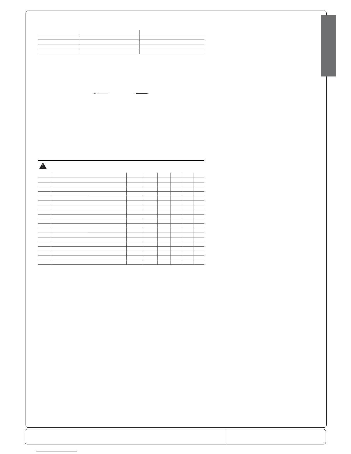
dn1 dP1
100
dn
and
dn2 dP2
100
dn
Example: with dn=65, dP1=90 min. and dP2=120 min.
Nominal defrost duration on main evaporator: 59 min.
Nominal defrost duration on auxiliary evaporator: 78 min.
Default: dn=65 => 65% of dP1 or dP2
dH: Proportional factor in the variation of the defrost interval
This parameter is used to increase or decrease the in uence of the e ective duration of the defrost, in relation to the nominal
duration, in the algorithm that manages the automatic variation of the defrost interval. By setting dH=0, the e ective duration has
no in uence on the duration of the defrost interval. Vice versa, dH = 100 achieves maximum e ciency. Default: dH=50
7.5 Alarm management parameters
Code Parameter Model UOM Type Min Max Def.
A0 Alarm and fan di erential MSYF °C/°F C 0.1 20 2.0
A1 Type of threshold AL and AH MSYF ag C 0 1 0
AL Low temperature alarm threshold MSYF °C/°F F -50 200 0.0
AH High temperature alarm threshold MSYF °C/°F F -50 200 0.0
Ad Low and high temperature signal delay MSYF min F 0 250 120
A4 Digital input 1 con guration (DI1) -SYF - C 0 14 0
M--- - C 0 14 3
A5 Digital input 2 con guration (DI2) MSYF - C 0 14 0
A6 Stop compressor from external alarm -SYF min C 0 100 0
A7 External alarm detection delay -SYF min C 0 250 0
A8 Enable alarms Ed1 and Ed2 -SYF ag C 0 1 0
A9 Digital input 3 con guration (DI3) - C 0 14 0
Ado Light management mode with door switch MSYF ag C 0 1 0
Ac High condenser temperature alarm -SYF °C/°F C 0.0 200 70.0
AE High condenser temperature alarm di erential -SYF °C/°F C 0.1 20 5.0
Acd High condenser temperature alarm delay -SYF min C 0 250 0
AF Light sensor OFF time -SYF sec C 0 250 0
ALF Antifreeze alarm threshold MSYF °C/°F C -50 200 -5.0
AdF Antifreeze alarm delay MSYF min C 0 15 1
Tab. 7.g
Note: par. A9 refers to the instruments with 3 digital inputs (ir33DIN, powercompact and MasterCella).
Important warning: for the set times to become immediately operational, the instrument needs to be turned o and on again. If
this operation is not carried out, timing resumes operation the next time it is used.
A0: Alarm and fan di erential
This is the di erential used for disabling high and low temperature alarms (AL and AH - see Figure 7.i) and for managing the fans
(see the F parameters). In the event of an alarm, as can be seen from the gure, the value of A0 in part determines the e ective
activation points of the temperature alarms. Default: A0=2.0 degrees.
A1: Type of threshold AL and AH
Used to select whether the values of parameters AL and AH are considered absolute thresholds or relative to the value of the set point.
A1 = 0 => AL and AH are considered as relative thresholds.
A1 = 1 => AL and AH are considered absolute thresholds.
Default: A1 = 0 => AL and AH are considered relative thresholds.
AL : Minimum temperature alarm
This is used to determine the activation threshold for the low temperature alarm.
Relative threshold for low temperature alarm = (set point) - (value of AL)
AL=0 => Alarm disabled;
Absolute threshold for low temperature alarm = value of AL.
AL=-50 => Alarm disabled.
Important: If the threshold AL is selected as relative, the value for disabling the alarm is 0, while if selected as absolute, the alarm
disabling value is -50.
Warnings for the relative threshold:
The value of AL does not indicate the actual alarm temperature, but the maximum permissible deviation from the set point; changing the set point automatically changes the low temperature alarm, while the maximum deviation allowed (=AL ) remains xed.
Note: the low temperature alarm features automatic reset (this means that if the temperature returns above the minimum value
set, the alarm signal is cancelled automatically).
Page 25

Doc. No.: 560001 EG
Page:25 Ed.1" 08-2014
From ser. no.:
set point
allarme bassa temperatura allarme alta temperatura
A0
A0
AL
Fig. 7.i
ENGLISH
Warnings for using the continuous cycle
The low temperature alarm is also used in the continuous cycle (see the description of parameter cc’.
In fact, if the temperature falls to the alarm level, the continuous cycle is stopped automatically, even if the selected time has not
yet elapsed. This deactivation, however, does not involve an alarm signal.
Default: AL =0 => low temperature alarm disabled.
Note: for the control probe alarm, the low temperature alarm is reset and monitoring reinitialised.
AH: High temperature alarm
This is used to determine the activation threshold for the high temperature alarm.
Relative threshold for high temperature alarm = (set point) + (value of AH)
AH=0 => Alarm disabled;
Absolute threshold for high temperature alarm = value of AH.
AH=200 => Alarm disabled.
Important: if the threshold AH is selected as relative, the value for disabling the alarm is 0, while if selected as absolute, the
alarm disabling value is 200
.
Warnings for the relative threshold:
• the value of AH does not indicate the alarm temperature, but the maximum permissible deviation from the set point; consequently, changing the set point automatically changes the high temperature alarm, while the maximum deviation allowed
(=AH) remains xed.
Warnings:
• the high temperature alarm has automatic reset: this means that if the temperature returns above/below the minimum value
envisaged, the alarm signal is cancelled automatically
• in the event of a control probe alarm, the high temperature alarm is reset and monitoring reinitialised.
Default: AH=0 => high temperature alarm disabled.
Ad: Temperature alarm delay
Indicates after how many minutes the temperature alarm is signalled when the temperature threshold is exceeded.
Warnings:
• Setting a delay for signalling the temperature alarm may help eliminate false alarms due to interference on the probe signal or
brief situations (for example, the door to the cold room opened for a short period);
• no temperature alarms are generated during the defrost and continuous cycle procedures;
• the temperature alarm is delayed by the time d8 after the defrost and by the time c6 after the continuous cycle. At the end of these
two times, the temperature alarm, if detected, is signalled without waiting for the time set for Ad. If d8 and c6 are set to zero, the
temperature alarm is signalled after the time Ad;
• as already indicated by the default value for parameters AL and AH, the instruments are programmed in the factory with the relevant
thresholds, and the high and low temperature alarms are disabled. The alarms, when enabled, activate the buzzer, if enabled, and
show a code on the display: HI for the high temperature and LO for the low temperature alarm.
The following conditions generate the temperature alarms:
• high temperature alarm: the temperature measured by the virtual control probe is above the threshold set for parameter AH;
• low temperature alarm: the temperature measured by the virtual control probe is below the threshold set for parameter AL.
Default: Ad=120 => 120 minute delay for the temperature alarms.
A4: Multifunction digital input con guration
In the ir33 series, this parameter and the model of controller used de ne the meaning of the multifunc tion digital input.
The possibilities are described below:
A4=0 Input not active: the multifunction digital input is not used and is the factory-speci ed con guration for all versions.
A4=1 Immediate external alarm: the digital input can be connected to an external alarm that requires immediate activation (for
example, high pressure alarm or compressor thermal overload). Speci cally, the alarm is detected when the contact opens (normal
operation with contact closed). The activation of the alarm:
• shows the message on the display (IA);
• activates the buzzer, if enabled;
• activates the alarm relay, if selected;
• involves the following actions on the actuators:
- compressor: operates depending on the values assigned to parameter A6 (stop compressor from external alarm).
- fans: continue to operate according to the fan parameters (F).
When stopping the compressor, the minimum ON time (c3) is ignored. When the alarm stops, the
defrost and continuous cycle can be performed again, and the compressor returns to normal operation.
Important warning: remember that in order to ensure the safety of the unit in the event of serious alarms, all the electromechanical
safety devices required to guarantee correct operation must be tted on the unit.
Note:
• if more than one digital input is con gured as the immediate alarm, the alarm will be generated when at least one of the inputs
is open.
• if control with two compressor steps is selected (with or without rotation, H1, H5 = 12 or 13) the immediate external alarm acts
on both steps.
A4=2 Delayed external alarm
The delayed external alarm is equivalent to the immediate external alarm (A4=1), except that this alarm is signalled after the
time A7 from when it is detected (‘dA’ signal). This con guration is especially useful for managing the low pressure alarm. In fact,
when starting for the rst time, the unit often detects a low pressure alarm due to the environmental conditions rather than the
malfunctioning of the unit.
Setting a delay for the alarm will avoid false signals. In fact, by suitably calculating the delay, if the low pressure is due to environmental
conditions (low temperature), the alarm will be automatically reset before the delay has elapsed.
Note:
• if ‘A7’=0, the activation of the alarm does not cause the compressor to operate according to the values assigned to the parameter
‘A6’ (stop compressor from external alarm); on the other hand, the ‘dA’ signal is displayed, the icon ashes, the buzzer and the
alarm relay (if selected) are activated;
Page 26
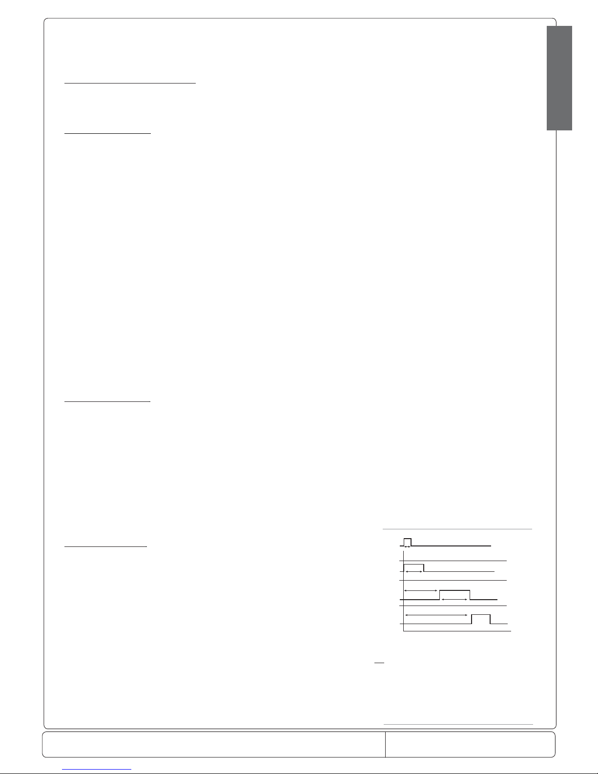
Doc. No.: 560001 EG
Page:26 Ed.1" 08-2014
From ser. no.:
d5 (3)
dP (2)
dP (1)
t
d5 (2)
defrost
defrost
defrost
timer
unit 1
unit 2
unit 3
defrost request
dP (3)
Fig. 7.l
ENGLISH
the delayed external alarm is thus signal-only.
• both the immediate and delayed external alarm have automatic reset;
• if more than one digital input is con gured as the delayed alarm, the alarm will be generated when at least one of the inputs is open;
• if control with two compressor steps is selected (with or without rotation, H1, H5 = 12 or 13) the delayed external alarm acts
on both steps.
A4 =3 The meaning varies according to the model used
Version ir33M = probe selection
This is used to exploit the digital input in order to show, on the display, the probe selected by parameter /tI or the rst enabled
probe (see parameters /A2, /A3, /A4, /A5). In practice, if the contact is open, the probe selected by parameter /tl is shown,
whereas, if the contact is closed, the rst enabled probe is shown.
For all other models = Defrost enabling
An external contact can be connected to the multifunction input to enable or inhibit the defrost.
• Contact open: the defrost is inhibited. Contact closed: the defrost is enabled.
• Contact closed without request from the controller: the defrost is not performed.
• Contact closed and defrost in progress: when the digital input is opened, the defrost is immediately stopped and the unit
restarts normal operation (without performing the dripping or post-dripping phases). The LED starts ashing to indicate that
the defrost request is pending, awaiting the next enabling signal (closing of the contact), when the defrost will be performed
completely.
Suggestion: this function is useful in the following situations, for example:
- multiplexed showcases with hot gas defrost. In these systems, defrosts must be performed by “islands”, and therefore, at any one
time, some islands are enabled to be defrosted, while others are disabled;
- to prevent defrosts on the units accessible by the public during opening times. Any defrost request arriving when the contact is
open will remain pending until the contact closes.
A4 = 4 Start defrost from external contact
This function used to start the defrost from an external contact.
If dI=0 and no defrost enabling signal related to the clock is set, the defrost can only be performed on start-up, from the digital
input, by the supervisor and from the keypad. This function is useful to run real time defrosts. To perform the defrosts, connect a
cyclical, mechanical or electronic timer to the digital input: When the contact on the timer closes, the defrost request is sent.
As seen in the description of parameter d5, a series of units can be connected to the same timer.
Important warning for versions operating on 12Vac and 12-24Vac
When connecting a series of units to the same timer, the best solution is to insulate all the contacts galvanically, inserting an intermediate relay for each contact. Setting a di erent value for d5 on each unit will avoid simultaneous defrosts.
Note: if more than one digital input is con gured to enable the defrost, the defrost will be disabled when at least one of the
inputs is closed.
A4 = 5 Door switch with compressor and fan stop
Setting A4=5 manages the cold room door switch. The behaviour of the door switch depends on whether the door is opened
with the light OFF or light ON. The need to di erentiate the two operating modes is mainly designed for controlling display cases
and cold rooms.
Case 1 - door opened with light OFF:
If the door is opened with the light OFF:
• the compressor and evaporator fans are switched o (to stop the fans only, set parameter A4=9);
• in the models tted with an auxiliar y relay programmed as the light output, the light is switched on;
• the reading displayed and the icon ash;
• the temperature alarms are disabled.
If the door remains open for longer than time d8, the controller restarts normal operation:
• compressor and fan ON, if requested;
• light ON (the auxiliary relay is selected as the light);
• the buzzer and the alarm relay are activated;
• the temperature alarms are enabled;
• the reading ashes.
To stop the reading from ashing, close the door. When the door is closed, the controller returns to normal operation, switching o
the light and enabling the temperature alarm after the delay time d8. The compressor is re-started observing any protection times
selected (see the C parameters).
Case 2: door opened with light ON:
SAssuming the user enters the cold room, turning on the light before entering, closing the door behind him, and then exits the room,
closing the door a second time. When the door is opened:
• the compressor the evaporator fans are switched o (to stop the fans only, set parameter A4=9);
• the light stays on (only in the models tted with an auxiliary relay programmed as the light output);
• the reading displayed and the icon ash;
• the temperature alarms are disabled
When the door is closed the rst time, the controller maintains the previous situation. When the door is closed the second time,
the controller returns to normal operation, switching o the light and enabling the temperature alarm after the delay time d8.
The compressor is re-started, observing any protection times selected (see the C parameters).
If the door remains open for a time longer than d8, the controller returns to normal operation:
• compressor and fan ON, if requested;
• light OFF;
• the reading ashes;
• the buzzer and the alarm relay are activated;
• the temperature alarms are enabled;
• when the door closes the temperature alarm delay d8 is not set.
If, after being closed for the rst time, the door remains closed for longer than time d8, or if the light is switched o manually, the
controller restarts normal operation:
• compressor and fan ON, if requested;
Key:
t= impulse from the timer to start the defrost:
the minimum duration must be 0.5 s.
dP (1)= maximum defrost duration on unit 1.
dP(2)= defrost delay from external contact for unit 2,
higher than dP(1) to prevent overlapping defrosts.
Same for d5(3) and dP(3).
Page 27
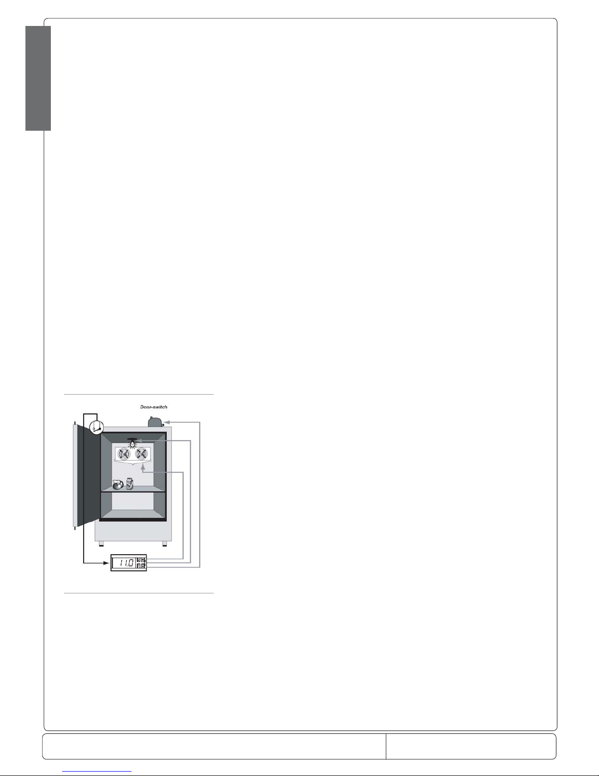
Doc. No.: 560001 EG
Page:27 Ed.1" 08-2014
From ser. no.:
Fig. 7.m
ENGLISH
• light OFF;
• the temperature alarms are enabled;
• the temperature alarm delay d8 is set.
If after the door is rst closed the light is switched o manually, the controller resumes normal operation.
Note:
1. if the light was previously switched on manually, when the door is closed for the second time, it is automatically switched o ;
2. if more than one digital input is con gured as the door switch, the door open status will be considered when at least one of
the inputs is open;
3. if control with two compressor steps is selected (with or without rotation, H1, H5 = 12 or 13), opening the door deactivates
both steps.
Warning: even when the fan is managed by the fan controller (see the F parameters), the fans are forced to stop when the door is
open. This algorithm resolves any problems relating to faults or malfunctions of the “door switch”.
A4 =6 Remote ON/OFF
The digital input can also be programmed as a remote ON/OFF switch. When the contact is closed, the controller is ON.
When the controller is OFF:
• the temperature is displayed alternating with the message OFF;
• the internal timer for parameter dI is updated. If dI expires when the unit is OFF, a defrost is performed when the unit is switched
on again;
• the auxiliary relay set as AUX or LIGHT remains active;
• the buzzer and the alarm relay are de-activated;
• the controller does not perform the control functions, defrosts, continuous cycle, signal the
temperature alarms and all other functions;
• the compressor protection times are observed;
• when the instrument is switched back on, all the functions are re-activated, with the exception of defrost on start-up, compres-
sor and fan delay on start-up.
Contact closed => ON.
The ON/OFF from external digital input has priority over the keypad and the supervisor.
If A4, A5, A9=6, the controller is ON with all the contacts closed
Note:
• if more than one digital input is con gured as the remote ON/OFF, the OFF status occurs when at least one of the inputs is open;
• if control with two compressor steps is selected (with or without rotation, H1, H5 = 12 or 13), the OFF status deactivates both steps.
A4 =7 Curtain switch
If the input is selected as a curtain switch, the controller modi es the set point when the contact closes, adding the value of
parameter r4; the new value is then used for all the functions relating to the set point (e.g. relative high and low temperature
alarms, control with dead band, control with two compressor steps, etc.).
When r4=3.0 (default value), the set point is increased by 3 degrees from the value used when the curtain is open.
Contact closed => curtain lowered.
If one of the auxiliary outputs is used to manage the light, lowering the curtain automatically switches the light o , while raising
it switches the light on.
Note: if more than one digital input is con gured as a curtain switch, the curtain open status occurs when at least one of the
inputs is open.
A4 = 8 Low pressure switch input for pump down
The low pressure alarm LP is signalled when the pressure switch signals a low pressure situation with the pump down valve
open and the compressor on, if the pump down function is active, or when the compressor is on. The low pressure alarm signal is
nonetheless delayed by the time in minutes set for parameter A7.
The low pressure alarm ‘LP ’ door stops the compressor. This parameter, together with parameters c7, c8, c9, H1 and H5, allows
management of the pump down algorithm.
Note: if control with two compressor steps is selected (with or without rotation, H1, H5 = 12 or 13), the low pressure alarm
deactivates both steps.
Contact open => low pressure.
Important:
If c7=0 (pump down disabled), the low pressure situation can still be detected. If more than one digital input is
con gured as the low pressure switch input, the low pressure alarm is activated when at least one of the inputs is open.
A4 =9 Door switch with fan stop only
Same as for option A4=5, with the di erence being that when opening the door, only the fans are stopped, rather than the
compressor and the fans.
Note: if more than one digital input is con gured as the door switch, the door open status occurs when at least one of the inputs
is open.
A4=10 Direct/Reverse operation
The digital input is used to select direct operation (cooling), contact open, or reverse operation (for heating), contact closed. For
example, a switch can be connected t select heating or cooling operation.
Depending on the value of parameter r3, the following con gurations are possible:
when r3=0 Contact open = direct operation with defrost control;
Contact closed = reverse operation.
When r3 =1 or r3 =2; Contact open = direct operation;
Contact closed = reverse operation.
WARNING: if A4=10, the status of the digital input has priority over the parameter r3, that is, the value assigned to parameter r3 is
ignored and only the status (open or closed) of the digital input is considered.
Note:
1. if more than one digital input is con gured as direct/reverse, the direct status occurs when at least one of the inputs is open;
2. the status of digital input selected as direct and reverse has priority over the operating mode set using parameter ‘r3’;
3. if control with two compressor steps is selected (with or without rotation, H1, H5 = 12 or 13), the DIRECT or REVERSE status
alarm acts on both steps.
A4 =11 Light sensor
Page 28
Doc. No.: 560001 EG
Page:28 Ed.1" 08-2014
From ser. no.:
ENGLISH
The digital input is used to read a light sensor (actually an analogue input, from which a digital signal is taken using the parameter or
threshold of the light sensor). The light sensor may be located:
• in the door stop,
• inside the cold room or cabinet.
In the rst case, , the sensor signals the opening and the closing of the door, because, with the door open, light is signalled, and
with the door closed, darkness is signalled (the sensor is located in the door stop and thus will be shadowed when the door is
closed). The inside light will be automatically switched on when the door is open and switched o when the door is closed. The
light stays OFF for a minimum time of 5 seconds, to avoid rapid, successive impulses of the light relay.
To select this operating mode, set AF=0.
In the second case, the light sensor signals the opening of the door of the cold room or the cabinet due to the outside light that
the sensor detects, thus activating the inside light. The closing of the door is measured by time, as the light inside the cold room
or cabinet will illuminate the sensor. After time AF (greater than 0), the inside light is switched o for 5 seconds. If the light sensor
signals darkness, the door must be closed and the light will therefore remain OFF. Otherwise, the door is still considered open and
the light is switched on again. To select this operating mode, set AF>0.
A4 =12 Activation of the AUX output
The digital input is used to activate/deactivate the AUX output, if con gured with parameter H1 or H5, with the following logic:
Digital input AUX output
open deactivation
close activation
Tab. 7.h
The output is activated/deactivated on closing/opening the contact, to make this operating mode
compatible with the presence of the AUX button and the control signal from the supervisor.
Note: if more than one digital input is con gured as AUX, the open status occurs when at least one of the inputs switches to open
status.
A4 =13 Door switch with compressor and fans o and light not managed.
Same as for A4=5, with the di erence that the light output is not modi ed.
Note:
1. the door management algorithm depends on the parameter ‘Ado’.
2. if more than one digital input is con gured as the door switch, the door open status will be considered when at least one of the
inputs is open.
A4 =14 Door switch with fans only o and light not managed.
Same as for A4=9, with the di erence that the light output is not modi ed.
Note: for A4/5= 13 or 14: the Ado door management algorithm is used in both cases.
Default: A4=0 => Digital input not active (for all other models).
The table below summarises the functions of the digital input corresponding to the value assigned to the variable A4.
Value of A4 Function Function ac tive LED on
0 input not active
1 immediate external alarm open = alarm open
2 delayed external alarm open = alarm open
3 for model M, select probes open = probe selected by parameter /tI closed =
rst probe enabled
3 other models, enable defrost closed= enabled
4 start defrost closing = defrost request
5 door switch with compressor and fans OFF open = door open
6 remote ON/OFF open = instrument o
7 curtain switch closed = cur tain closed
8 low pressure switch open = low pressure
9 door switch with fans OFF only open = door open
10 direct / reverse open = direct
11 light sensor above the threshold = o
12 activation of AUX output open = deactivation
13 door switch with compressor and fans o , light not
managed
open = door open
14 door switch with fans only o , light not managed open = door open
Tab. 7.h
Note:
• if more than one digital input is con gured in the same way, the activation of the associated function will be enabled if at least
one of these is open.
• for control with two compressor steps (with or without rotation, H1=12 or 13) the function associated with the digital inputs is
activated on both.
A5: Con guration of the second multifunction digital input.
For this parameter the same description relating to parameter A4 is valid, obviously referring to the second digital input. Default:
A5=0 => Digital input not active.
A6: Stop compressor from external alarm (multifunction input)
The meaning of this parameter is similar to that of parameter c4 (duty setting).
If an external alarm occurs (immediate or delayed), the compressor works for a time equal to the value set for parameter A6 (in
minutes), while it remains OFF for a xed period of 15 minutes.
Special cases:
A6=0 the compressor is always OFF;
A6=100 the compressor is always ON.
Page 29

Doc. No.: 560001 EG
Page:29 Ed.1" 08-2014
From ser. no.:
ENGLISH
The fans continue to be managed according to the set parameters (see category F). If duty setting for the probe alarm (parameter
c4) is also active, the controller uses the value of A6.
Note: if control with two compressor steps is selected (with or without rotation, H1, H5 = 12 or 13), the stop compressor acts on
both steps.
Default: A6=0 => compressor OFF in the event of external alarms.
A7: Delay in detecting the external alarm (multifunction input)
Establishes the delay (in minutes) in detecting an external alarm, if selected as a delayed external alarm (A4, A5=2) or the signal
of the low pressure (LP) alarm).
Note: if A7= 0, in the event of delayed alarms from digital input (A4 or A5 or A9= 2), the controller does not act on the control
outputs.
A8: Enable signals Ed1 and Ed2
The alarms Ed1 and Ed2 signal the end of the defrost due to maximum duration of the defrost time dP1/dP2 and can be disabled
by setting A8=0. The warnings Ed1 and Ed2, if enabled, are cancelled at the start of the following defrost or can be reset manually
by pressing the
PRG and AUX buttons for more than 5 seconds. Default: A8=0 => warnings Ed1 and Ed2 disabled.
Ac: Condenser high temperature alarm
If a probe is set as the condenser probe, the condenser temperature can be monitored to signal the high temperature alarm,
probably due to obstruction or fouling. If the condenser temperature is > Ac+ (AE/2), the pre-alarm is signalled, displaying the
alarm message cht. If in the pre-alarm situation, the condenser temperature falls to < Ac, the pre-alarm is reset and the signal
cht is cancelled. If the condenser temperature increases to > Ac + AE, the alarm CHt is activated and the compressor is stopped.
This alarm is delayed by the time Acd, from when the alarm threshold AC is exceeded. The alarm can only be reset manually. In the
event of a condenser probe fault, the alarm and pre-alarm are activated.
Note: if control with two compressor steps is selected (with or without rotation, H1= 12 or 13) the high condenser temperature
alarm acts on both steps.
Important:
1. if no condenser probe is selected, the condensing temperature alarm and pre-alarm are disabled.
2. the condenser fans can be controlled in on/o mode; for this function, refer to parameters F4 and F5.
Default: Ac=70.0 degrees.
AE: High condenser temperature alarm di erential
This is the di erential used for activation of the high condenser temperature alarm and control of the condenser fans.
Default: AE=5.0.
Acd: Condenser high temperature alarm delay
The parameter Acd can be used to set a delay on the activation of the condenser high temperature alarm. When the threshold
Ac + AE is exceeded, the alarm delay timer is started. If, when the delay time Acd has elapsed, the temperature is still above the
threshold, the alarm CHt is activated.
If the condensing temperature falls below Ac, the timer is reset and the alarm CHt is not displayed.
Default: Acd=0 => 0 minutes, immediate high condenser temperature alarm.
AF: Light sensor OFF time
Used to manage the light sensor, connected to a digital input, as:
AF= 0 sensor in the door stop
AF> 0 sensor inside the cold room or cabinet
When AF=0 the inside light is switched on when the sensor detects light, and is switched o when the sensor detects darkness.
The light is switched o for a minimum of 3 seconds, so as to avoid close successive impulses of the light relay.
Note: the sensor must be positioned so as to detect darkness when the door is closed.
When AF>0, the inside light is switched on when the sensor detects light. After a time in seconds equal to AF, the light is
switched o for 5 seconds to check if the door has been closed. If darkness is detected, the inside light remains OFF, but if light is
detected, the inside light is switched back on (after a
minimum time of 3 seconds) and the same cycle starts again. Default: AF = 0.
Page 30
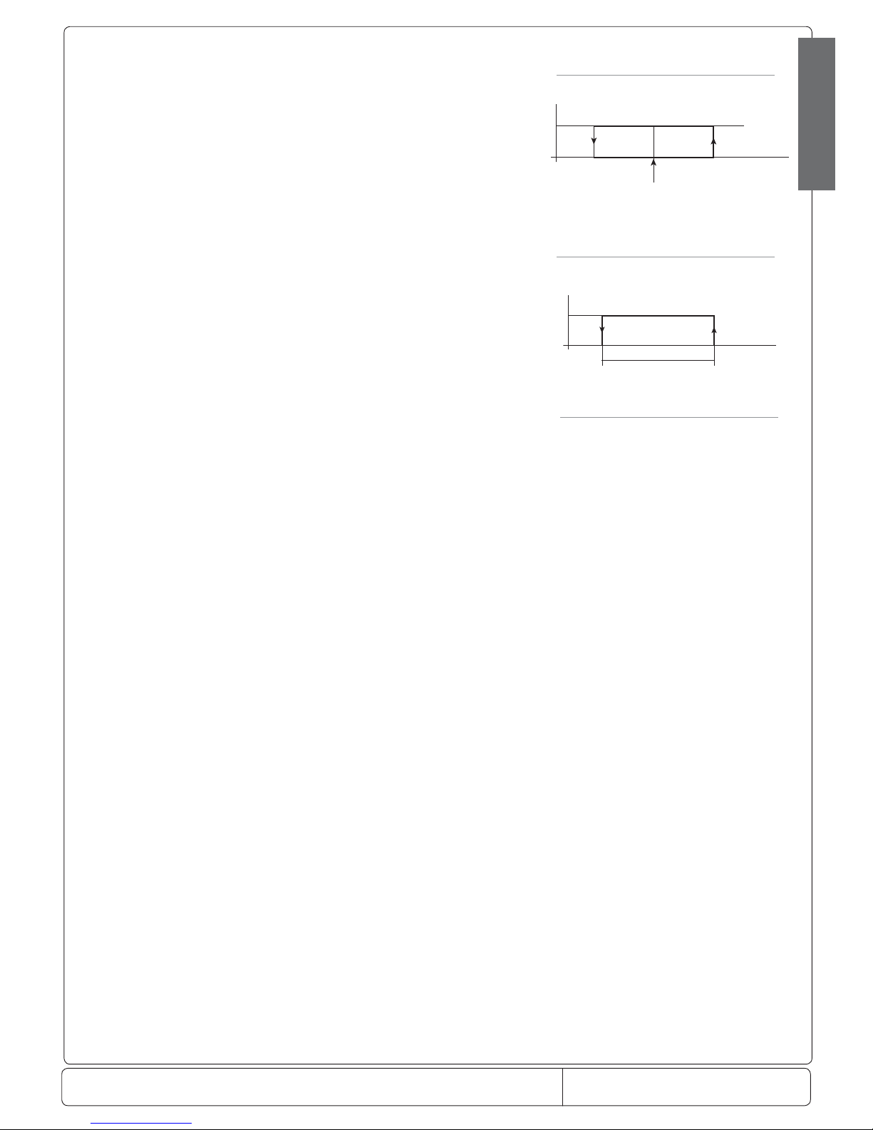
Doc. No.: 560001 EG
Page:30 Ed.1" 08-2014
From ser. no.:
Allarme “CHt” e o refrigerazione (ripristino manuale)
temp. condensatore
Preallarme
solo visualizzazione allarme “cht”
(ripristino automatico)
“AC” - “AE”/2
“Ac ”“Ac-AE”
ON
temp. condensatore
“AE”
“Ac ”
Fig. 7.m
Fig. 7.n
ENGLISH
ALF: Antifreeze alarm threshold
De nes the temperature value below which the antifreeze alarm is detected, with the message AFr.
The function is active if a probe has been set as an antifreeze probe, /A2, /A3, /A4, /A5= 4 and is delayed by the time set for
parameter AdF.
The antifreeze alarm stops the compressor and activates the alarm relay, if H1 or H5=0, 1, and has manual reset.
The antifreeze alarm stops the compressor (stops cooling operation) and activates the alarm relay, if ‘H1’=0, 1 or ‘H5’=0, 1.
The alarm is reset manually or from the supervisor.
Note: if control with two compressor steps is selected (with or without rotation, H1 = 12 or 13) the antifreeze alarm acts on both
steps.
Default: ALF= -5.0.
AdF: Antifreeze alarm delay.
Sets the delay for detecting the antifreeze alarm.
Default: AdF= 1.
Page 31
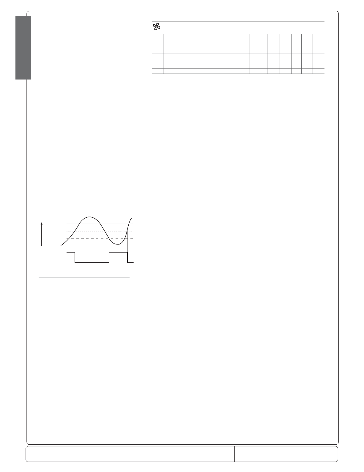
Doc. No.: 560001 EG
Page:31 Ed.1" 08-2014
From ser. no.:
ON
OFF
Amb.
Amb. F1
Amb. F1 - A0
Evap.
Evap. Fan
temperatura
Fig. 7.o
ENGLISH
7.6 Fan management parameters
Code Parameter Models UOM Type Min Max Def.
F0 Fan management ---F ag C 0 2 0
F1 Fan start temperature ---F °C/°F F -50 200 5.0
F2 Fan OFF with compressor OFF ---F ag C 0 1 1
F3 Fans in defrost ---F ag C 0 1 1
Fd Fan OFF after dripping ---F min F 0 15 1
F4 Condenser fan stop temperature MSYF °C/°F C -50 200 40
F5 Condenser fan start di erential MSYF °C/°F C 0.1 20 5.0
Tab. 7.l
The ir33 series controllers manage the evaporator fans in the following modes:
• always ON;
• ON only when the compressor is ON;
• ON according to evaporator and room temperature.
F0: Fan management
The fans can be always on or managed by the “fan controller”, which controls them according to the temperature measured by the
defrost and virtual control probes.
The evaporator fans can be stopped in the following situations:
• when the compressor is OFF (see parameter F2);
• during defrosts (see parameter F3);
• during the dripping period (see parameter dd);
• and for a further post- dripping period (see parameter Fd);
• in defrost they can be on or o (see parameter F3).
The following values are allowed for this parameter:
F0=0 fans always ON;
F0=1 fans controlled according to the temperature di erence between the virtual control probe and the evaporator temperature;
F0=2 fans controlled according to the evaporator temperature.
Warning: remember that if a dripping period is set (dd=0), the fans are stopped irrespective of the value of F0.
Default: F0=0 => fans always ON, not managed by the “fan controller”.
F1: Fan start temperature (parameter valid only if F0 =1 or 2)
When F0=1, parameter F1 indicates the minimum di erence between room temperature and evaporator temperature for the fans
to be started. Therefore, when:
• evaporator temperature < (virtual probe – F1-A0), the fans are ON;
• evaporator temperature > (virtual probe – F1), the fans are OFF.
When stopped, the fans can start again when the di erence between the two probes is equal to F1+A0, where A0 is the “fan
controller” di erential (see Figure 7.o).
When F0=2, parameter F1 indicates the absolute temperature for starting the fans, that is:
• evaporator temperature < (F1-A0), the fans are ON;
• evaporator temperature > (F1), the fans are OFF.
Notes:
• if there are two evaporators and therefore two evaporator probes, control will be performed using the maximum value read by
the two probes, to ensure that the fans are started when both evaporators reach the set temperature.
• in the event of errors on the control probes, the fans are always on.
Default: F1=5 =>(if F0=1 or 2), the fans remain ON while the evaporator is 5 degrees colder than the room temperature.
F2: Fans OFF with compressor OFF (according to the value of F0)
Used to decide whether the fans must operate according to the rules set for parameter F0 (with the exception of the defrost cycle,
parameters F3, dd and Fd are displayed) or when the compressor is active.
• F2=0 => the fans are always ON (F0=0) or when requested by the fan controller (F0=1,2), even when the compressor is OFF;
• F2=1 => the fans are OFF when the compressor is OFF.
Note: if control with two compressor steps is selected (with or without rotation, H1 or H5= 12 or 13) and parameter F2 =1, the
fans are o when both the compressors are o .
Default: F2=1 => fans OFF with compressor OFF.
F3: Fans in defrost
This is used to decide whether the fans should operate or not during the defrosts.
F3=0 => the fans operate during defrosts;
F3=1 => the fans do not operate during defrosts.
Remember that during the dripping time and post-dripping time, if speci ed, the fans are always OFF. Default: F3=1 =>
evaporator fans OFF during the defrost.
Fd: Fans OFF for post-dripping
The fans, after defrosting, can be stopped for a further period beyond dd (in minutes), de ned by the value of Fd. This is useful
to allow the evaporator to return to its operating temperature after defrosting, thus avoiding forcing “hot” air into the refrigerated
environment. In the event of management by fan controller, the time Fd does not need to be set, as the controller starts the fans
again when the evaporator reaches its operating temperature. If the “fan controller” is active (F0=0), when assigning to Fd a value
other than zero, the fans remain OFF for a time equal to the value of Fd, irrespective of the evaporator temperature. Default: Fd=1
=> 1 minute stop for post-dripping.
F4: Condenser fan stop temperature
This is used to select the temperature at which the condenser fans should be switched OFF. If setting the auxiliary relay as the
condenser fan output (see parameter H1), this will enable adjustments according to the diagram in Figure 7.p:
When the compressor is rst started, the fans are switched ON at F4 + 0.2 degrees to compensate for rapid temperature increases
that are not easy for the probe to follow.
After this, control is performed normally, i.e.:
• on: F4 + F5
Page 32
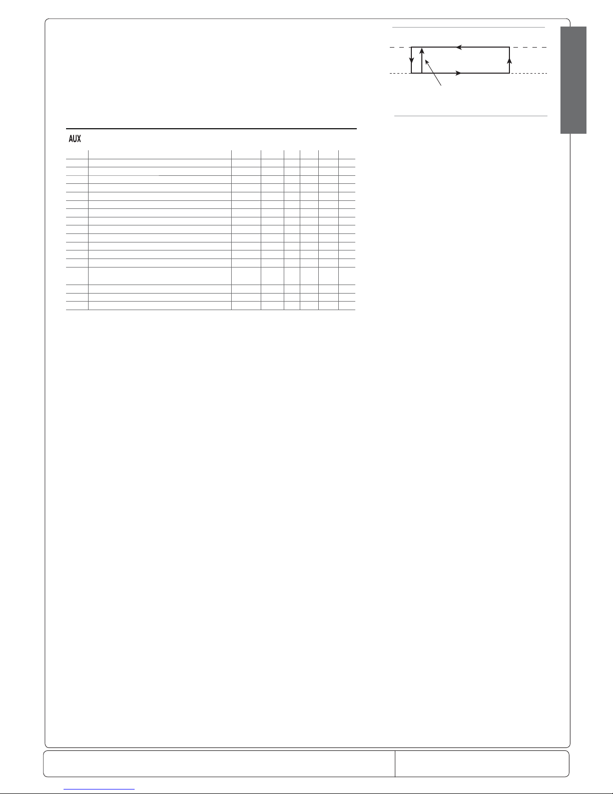
Doc. No.: 560001 EG
Page:32 Ed.1" 08-2014
From ser. no.:
ON ventole
prima accensione
“F4” + “F5”
“F4” 0.2
temp. condensatore
Fig. 7.p
ENGLISH
• o : F4.
In the event of condenser probe errors, the condenser fan output, if selected, is activated.
Important: If no condenser probe is selected, the condenser fan output, if selected, is disabled.
Default: F4=40.0 degrees.
F5: Condenser fan start di erential
This is the di erential used to control the condenser fans.
Default: F5=5.0.
7.7 General con guration parameters
Code Parameter Models UOM Tipo Min Max Def.
H0 Serial address MSYF - C 0 207 1
H1 Function of AUX output MSYF ag C 0 13 1
H2 Disable keypad/IR MSYF ag C 1 6 1
H3 Remote control enabling code MSYF - C 0 255 0
H4 Disable buzzer MSYF ag C 0 1 0
H5 Function of relay 5 - C 0 10 3
H6 Lock keypad MSYF - C 0 255 0
H7 Select keypad MSYF ag C 0 1 0
H8 Select activation of output with time band MSYF ag C 0 1 0
H9 Enable set point variation with time band MSYF ag C 0 1 0
HPr Print pro le MSYF - C 0 15 0
Hdn Number of default parameter sets available MSYF - C 0 6 0
Hrl Enable the remote signalling of the status of the master light relay MSYF ag C 0 1 0
HrA Enable the remote signalling of the status of the master auxiliary
relay
MSYF ag C 0 1 0
HSA Enable alarms from other devices in local network MSYF ag C 0 1 0
In Establishes if the unit is normal, master or slave MSYF - C 0 6 0
Hdh Anti-sweat heater o set MSYF °C/°F C -50 200 0.0
Tab. 7.m
Note:
- par. H5 refers to the instruments with 5 relays (ir33DIN, powercompact and MasterCella);
- parameters H7, HPr, Hdn, HrL, HrA, HsA and In are masked and consequently only visible using the programming kit (IROPZPRG00).
H0: Serial address
This is used to assign to the instrument an address it responds to when connected to a supervisory or telemaintenance system.
Default: H0=1.
H1: Operating mode: logic of output AUX1
Establishes whether the fourth relay is used as an auxiliary output.
The following functions can be associated:
H1=0 - alarm output normally energised. The relay is de-energised when an alarm occurs. The AUX output in “alarm” mode can be
set to operate either with the relay energised or de-energised. The latter mode ensures maximum safety, because the alarm is also
activated in the event of power failures or disconnection of the cables.
H1=1 - alarm output normally de-energised: the relay is energised when an alarm occurs.
H1=2 - auxiliary output: the actuator connected can be switched ON/OFF using the AUX button. Switching the actuator ON/OFF
is signalled by the icon on the display.
H1=3 - light output: the light on the unit can be switched on/o when the door is opened, pressing the LIGHT button, enabling the
digital input switch door or the curtain switch digital input (see parameter A4, A, A6) if the door switch is enabled (see parameter
A4). In this case, the light is switched o when the door is closed, unless previously switched o from the keypad. Switching the
light on/o is signalled by the icon on the display.
H1=4 - auxiliary evaporator defrost output: a heater or reversing valve can be controlled to perform an electric heater defrost or hot
gas defrost on the auxiliary evaporator.
H1=5 - pump down valve output: the activation and deactivation of the pump down valve can be controlled.
H1=6 - condenser fan output: if the high condenser temperature alarm is activated, the output can be used to control the condenser
fans (see parameter Ac and F4).
H1=7 - delayed compressor output: the output is activated a few seconds after the compressor starts (the delay is established by
parameter c11, deactivation of the compressor output corresponds to immediate deactivation of the delayed compressor. If this operating
mode is set, it is also active during the compressor pump down and autostart phases, if selected with the appropriate parameters.
H1=8 - auxiliary output with deactivation when OFF: in the o status, the auxiliary output cannot be activated. When starting again,
the auxiliary output returns to the previous status.
H1=9 - light output with deactivation when OFF: in the o status, the light cannot be activated. When starting again, the light
returns to the previous status.
H1=10 - no function associated with the output. In this case, the logical output AUX1 is not used for any function. If logical outputs
AUX1 and AUX2 are associated with the same relay, this setting means the relay in question will only be associated with AUX2.
Vice-versa, using this setting for AUX2, the relay will only be associated with AUX1. This possibility is useful when there is just one
auxiliary relay, and it needs to be used alternatively as a light relay, associated with the light button and icon, or as an AUX relay,
associated with the AUX button and icon.
H1=11- reverse output in control with dead band: used to activate control with dead band (‘St’ ‘rd’ ‘rn’ ‘rr’), using the auxiliary output
aux1 for the reverse function.
H1=12 - second compressor step output.
H1=13 - second compressor step output with rotation .
Important: mode ‘H1’=0 is also useful for signalling power failures.
Default: H1=1 => relay energised with alarm active. Available on all models with aux output.
Page 33
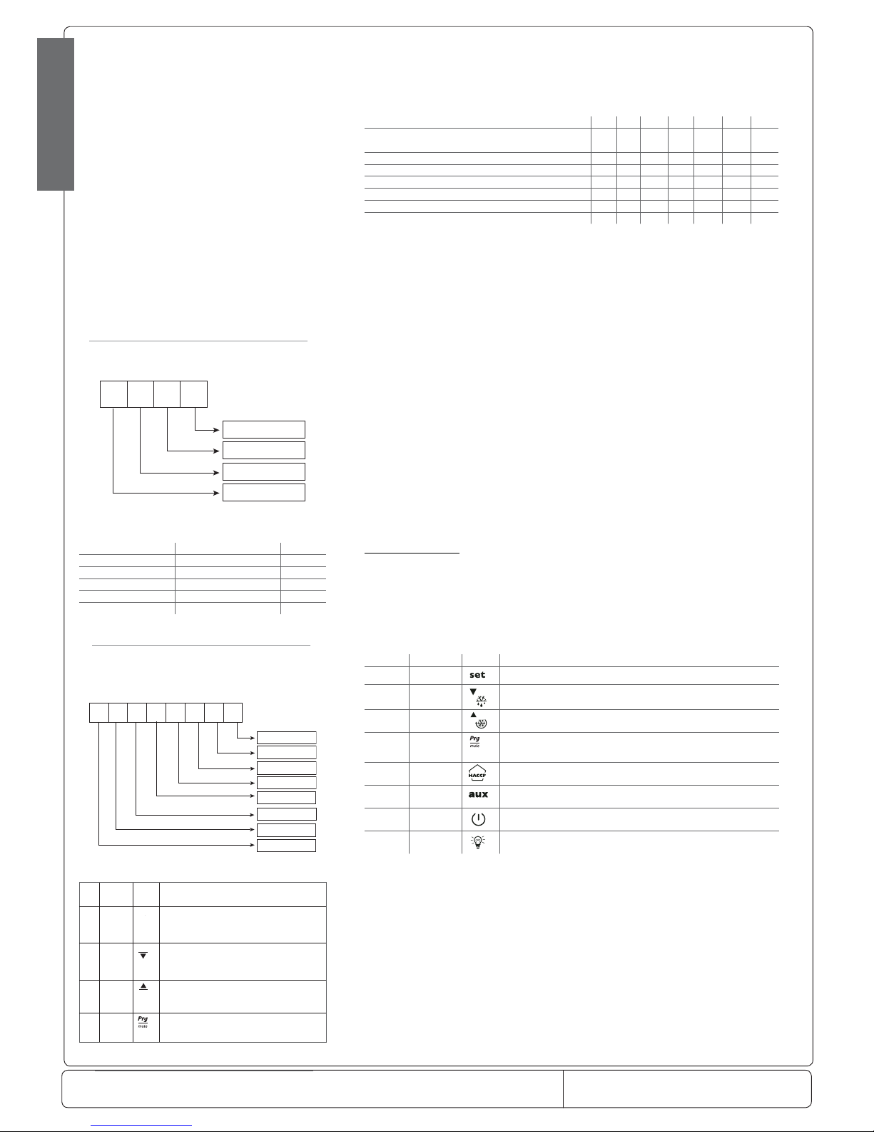
Doc. No.: 560001 EG
Page:33 Ed.1" 08-2014
From ser. no.:
Fig. 7.q
8421
3210
Tasto Set
Tasto down/def
Tasto up/aux
Tasto prg/mute
Tastiera standard
8421
3210
Tasto Set
Tasto down/def
Tasto up/cc
Tasto prg/mute
Tastiera standard
64 32 16
7654
128
Tasto haccp
Tasto aux
Tasto on/off
Tasto luce
Fig. 7.r
ENGLISH
H2: Disable keypad and/or remote control
Parameter ‘H2’ can be used to inhibit some functions relating to the use of the keypad, for example, the modi cation of the parameters
and the set point if the unit is accessible to the public.
The following options are available:
Parameter “H2” 0 1 2 3 4 5 6
HACCP
PRG/MUTE (mute)
UP/aux • • •
DOWN/DEF (defrost) • • •
set (modi cation of type F parameters) • • • • •
Modi cation of the set point • • • •
Modi cation from the remote control • •
ON/OFF • •
Tab. 7.n
When the set point modi cation and parameter modi cation functions are inhibited, neither the set point nor the type F parameters can be changed, while their values can still be displayed. The type C parameters, however, being password protected, can also
be modi ed from the keypad, following the procedure described previously. With the remote control disabled, only the values of
the parameters can be displayed, but they cannot be modi ed; in addition, the mute, defrost, continuous cycle, aux (auxiliary 1),
light (auxiliary 2) and on/o functions are disabled.
Warnings: If H2=2 or H2=3 is set on the remote control, this is immediately
disabled. To re- enable the remote control, set H2=0 or H2=1 on the keypad.
Default: H2=1=> all enabled
H3: Enabling code for programming from the remote control
Parameter H3 assigns an access code to the remote control. As already described, this allows the remote control to be used when
there is more than one controller present on the same panel, without the risk of interference. For further details, see the paragraph
on the use of the remote control.
Default: H3=00 => programming from the remote control without code.
H4: Disable buzzer
This parameter can have two values:
H4=0 buzzer enabled;
H4=1 buzzer disabled
Default: H4=0=> buzzer enabled. Available on all models.
H6: Lock keypad
Using the corresponding bits, the functions relating to the individual buttons on the keypad can be enabled/disabled, according to
the following relationships:
Total (value of parameter H6): to calculate the value to be assigned to parameter H6, simply sum the values assigned to the
functions that should be disabled.
For ir33, ir33power and ir33DIN see Table 7.q, for powercompact, powercompact small and mastercella see Table 7.q.
Important: the functions disabled using parameter H6 are added to those disabled using parameter H2.
Example: disable the “SET button”, “AUX button”:
ir33, ir33power and ir33DIN: 1+4 = 5 = value or parameter H6;
powercompact, powercompact small and mastercella: 1+32 = 33 = value of parameter H6.
Bit Value Button Functions that can be enabled/disabled
01 Report printing procedure
12
Defrost
24
Continuous cycle
38
Mute
416
Enter HACCP
532
Enable/disable auxiliary output 1
664
On/O
7 128
Enable/disable auxiliary output 2
Tab. 7.o
Default: H6=0 => all buttons disabled.
H8: Select light or AUX output to activate with time band.
This parameter can be used to select the output that is activated or deactivate according to the time band (see parameters tON
and tOF).
H8=0=> Time band linked to output con gured as the light.
H8=1=> Time band linked to output con gured as AUX.
Note: the output being controlled (light or AUX) must be available and selected with parameter H1.
Default: H8=0 => Time band linked to the light.
H9: Enable set point variation with time band.
This parameter can be used to enable the variation of the set point according to the time band (see parameters ton and toF). The
controller modi es the set point by adding the value of parameter r4 (to the time toF), the new value is used for all the functions
relating to the set point (e.g. relative high and low temperature alarms, control with dead band, control with two compressor
steps etc.).
ir33, ir33power and ir33DIN:
powercompact, powercompact small and MasterCella keypad
Value
Function Disabled +
set button 1
down/def button 2
up/aux button 4
prg/mute button 8
Tab. 7.p
Bit Mask But-
ton
Functions that can be enabled/disabled
01
S
et
Enter HACCP;Report printing procedure
12
def
Defrost;Continuous cycle;Enter HACCP
24
aux
Enable/disable auxiliary output 1; Continuous cycle
38
Mute
Tab. 7.q
Page 34

Doc. No.: 560001 EG
Page:34 Ed.1" 08-2014
From ser. no.:
ENGLISH
H9=0 => Set point variation with time band disabled.
H9=1 => Set point variation with time band enabled.
Note: When r4=3.0 (preset value) the set point is increased by 3 degrees from the value used before toF, at ton the value of the
set point will be the value set for parameter St.
As the time band set by ton and toF is related to the output auxiliary selected using parameter H8, the corresponding output will
switch on at ton, and will switch o at toF.
Therefore, when H9=1, the following will be true:
- ton : normal set point and selected output on.
- toF : set point + r4 and selected output o .
Default: H9=0 => Function disabled.
rs only.
Hdh: Anti-sweat heater o set
This represents the o set from the set point for the anti-sweat heater function. If Hdh = 0, the anti-sweat heater function is
disabled. The anti-sweat heater function is used to maintain the aux 1 or 2 output, con gured as the light or aux (H1 or H5= 2,
3, 8, 9) deactivated while the control temperature (virtual probe) is less than ‘St’ + ‘Hdh’ when the instrument is rst powered up,
the ‘HI’ ‘IA’ ‘dA ‘CHt’ ‘EE’ ‘EF’ ‘rE’ alarms are reset.
During the aforementioned alarms, the aux 1 or 2 output, con gured as above, is deactivated.
The function is active, if the light or aux functions are set to be deactivated when o ,‘H1’ or ‘H5’=8, 9, even when switching the
controller on.
Default: Hdh =0.0 => function disabled (C°)
Hdh =32 => function disabled (°F).
In: select normal, master or slave unit (masked parameter).
The parameter In establishes whether the unit is normal, master or slave. The maximum number of slaves in a sub-network is 5.
• Normal: stand-alone unit
• Master: Master unit. Allows the synchronisation of the defrosts, remote signalling of the light and aux relays and the alarms, and
the downloading of the parameters.
• Slave: Slave unit. Unit part of a local network serving the master.
The following table shows the values of the parameter:
In: 0 = No Master-Slave (normal)
1 = Master
2 = Slave 1
3 = Slave 2
4 = Slave 3
5 = Slave 4
6 = Slave 5
Note: the synchronisation of the multiplexed defrost is activated only on Master and Slave controllers.
Default: In=0 => normal.
Page 35
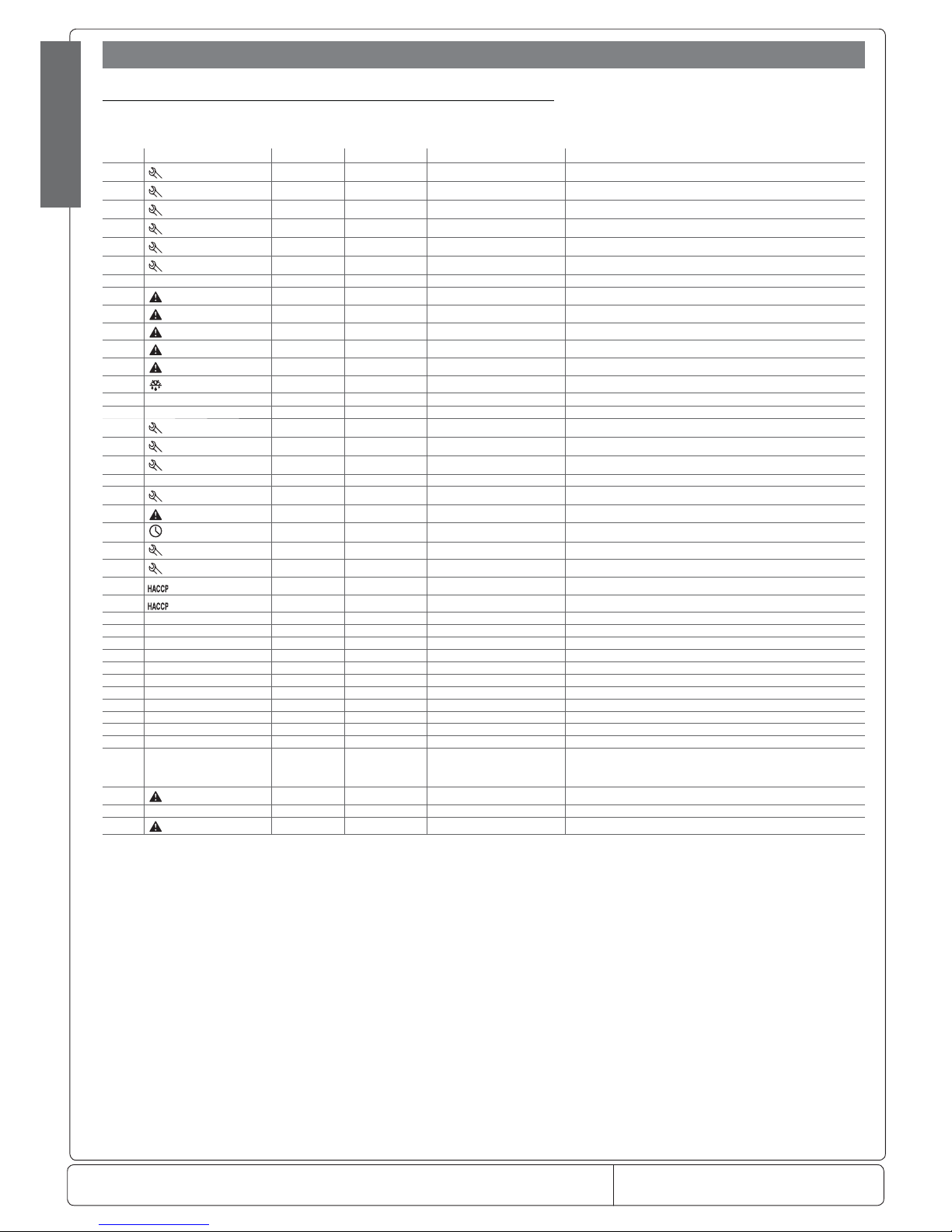
Doc. No.: 560001 EG
Page:35 Ed.1" 08-2014
From ser. no.:
ENGLISH
8.1 Summary table of alarms and signals: display, buzzer and relay
The following table describes the alarms and signals on the controller, with their description, the status of the buzzer, the alarm
relay and the reset mode.
Code Icon on the display Alarm relay Buzzer Reset Description
rE
ashing
on on automatic virtual control probe fault
E0
ashing
o o automatic room probe S1 fault
E1
ashing
o o automatic defrost probe S2 fault
E2
ashing
o o automatic probe S3 fault
E3
ashing
o o automatic probe S4 fault
E4
ashing
o o automatic probe S5 fault
‘___’ No o o automatic probe not enabled
LO
ashing
on on automatic low temperature alarm
HI
ashing
on on automatic high temperature alarm
AFr
ashing
on on manual antifreeze alarm
IA
ashing
on on automatic immediate alarm from external contact
dA
ashing
on on automatic delayed alarm from external contact
dEF
on
o o automatic defrost running
Ed1 No o o automatic/manual defrost on evaporator 1 ended by timeout
Ed2 No o o automatic/manual defrost on evaporator 2 ended by timeout
Pd
ashing
on on automatic/manual maximum pump down time alarm
LP
ashing
on on automatic/manual low pressure alarm
AtS
ashing
on on automatic/manual autostar t in pump down
cht No o o automatic/manual high condenser temperature pre-alarm
CHT
ashing
on on manual high condenser temperature alarm
dor
ashing
on on automatic door open too long alarm
Etc
ashing
o o automatic/manual real time clock fault
EE
ashing
o o automatic Eprom error, unit parameters
EF
ashing
o o automatic Eprom error, operating parameters
HA
ashing
o o manual HACCP alarm, HA
HF
ashing
o o manual HACCP alarm, HF
rCt Signal o o automatic instrument enabled for programming from the remote control
Add Signal o o automatic automatic address assignment procedure in progress
Prt Signal o o automatic printing report
LrH Signal o o automatic activation of low relative humidity procedure
HrH Signal o o automatic activation of high relative humidity procedure
ccb Signal start continuous cycle request
ccE Signal end continuous cycle request
dFb Signal start defrost call
dFE Signal end defrost call
On Signal switch ON
o Signal switch OFF
rES Signal reset alarms with manual reset
reset HACCP alarms
reset temperature monitoring
n1 - n6
ashing
on on automatic indicates an alarm on unit 1-6 in the network.
dnL Signal download in progress
d1 - d6
ashing
o o download with errors on unit 1-6.
Tab. 8.a
The buzzer sounds if enabled by parameter H4.
The alarm relay is activated if auxiliary output 1 (H1) has been assigned the alarm relay function.
Note: the buzzer is not a ected by the CAREL supervisor y system.
8. ALARMS AND SIGNALS
Page 36
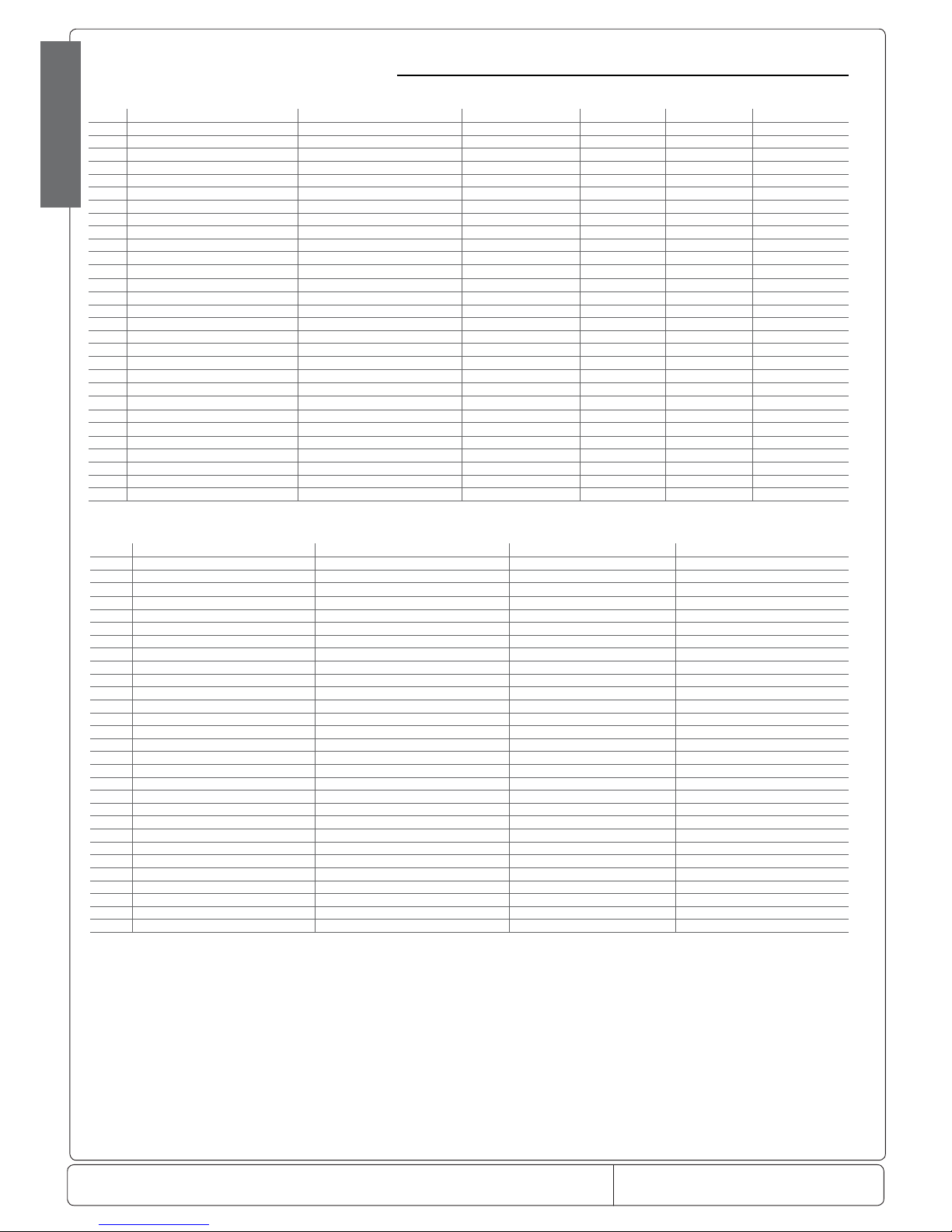
Doc. No.: 560001 EG
Page:36 Ed.1" 08-2014
From ser. no.:
ENGLISH
8.2 Table of alarms and signals: functions enabled/disabled
The following table highlights the functions that are enabled and disabled in the various alarm situations.
Code PD valve Compressor Defrost Evap. fans Cond. fans Continuous cycle
rE Duty setting (c4) Duty setting (c4) unchanged unchanged unchanged unchanged
E0 Duty setting (c4) Duty setting (c4) unchanged unchanged unchanged unchanged
E1 unchanged unchanged unchanged unchanged unchanged unchanged
E2 unchanged unchanged unchanged unchanged unchanged unchanged
E3 unchanged unchanged unchanged unchanged unchanged unchanged
E4 unchanged unchanged unchanged unchanged unchanged unchanged
‘___’ unchanged unchanged unchanged unchanged unchanged unchanged
LO unchanged unchanged unchanged unchanged unchanged unchanged
HI unchanged unchanged unchanged unchanged unchanged unchanged
AFr o o unchanged unchanged unchanged unchanged
IA Duty Setting (A6) Duty setting (A6) unchanged unchanged unchanged unchanged
dA Duty setting (A6) if A7<>0 Duty setting (A6) if A7<>0 unchanged unchanged unchanged unchanged
dEF unchanged unchanged unchanged unchanged unchanged unchanged
Ed1 unchanged unchanged unchanged unchanged unchanged unchanged
Ed2 unchanged unchanged unchanged unchanged unchanged unchanged
Pd unchanged unchanged unchanged unchanged unchanged unchanged
LP o o unchanged unchanged unchanged unchanged
Ats unchanged unchanged unchanged unchanged unchanged unchanged
cht unchanged unchanged unchanged unchanged unchanged unchanged
CHt unchanged o o unchanged unchanged unchanged
dor unchanged unchanged unchanged unchanged unchanged unchanged
Etc unchanged unchanged unchanged unchanged unchanged unchanged
EE o o not per formed o o not performed
EF o o not performed o o not per formed
HA unchanged unchanged unchanged unchanged unchanged unchanged
HF unchanged unchanged unchanged unchanged unchanged unchanged
n1-n6 unchanged unchanged unchanged unchanged unchanged unchanged
dnL unchanged unchanged unchanged unchanged unchanged unchanged
d1 - d6 unchanged unchanged unchanged unchanged unchanged unchanged
Tab. 8.b
Code
AUX dead zone
AUX light anti-sweat AUX auxiliary anti sweat AUX second step
rE o o o Duty setting (C4)
E0 o o o Duty setting (C4)
E1 unchanged unchanged unchanged unchanged
E2 unchanged unchanged unchanged unchanged
E3 unchanged unchanged unchanged unchanged
E4 unchanged unchanged unchanged unchanged
‘___’ unchanged unchanged unchanged unchanged
LO unchanged unchanged unchanged unchanged
HI unchanged o o unchanged
AFr unchanged unchanged unchanged o
IA o o o Duty setting (A6)
dA o if A7<>0 o if A7<>0 o if A7<>0 Duty setting (A6) if A7<>0
dEF unchanged unchanged unchanged unchanged
Ed1 unchanged unchanged unchanged unchanged
Ed2 unchanged unchanged unchanged unchanged
Pd unchanged unchanged unchanged unchanged
LP unchanged unchanged unchanged o
Ats unchanged unchanged unchanged unchanged
cht unchanged unchanged unchanged unchanged
CHt unchanged o o o
dor unchanged unchanged unchanged unchanged
unchanged unchanged unchanged unchanged
EE o o o o
EF o o o o
HA unchanged unchanged unchanged unchanged
HF unchanged unchanged unchanged unchanged
n1 - n6 unchanged unchanged unchanged unchanged
dnL unchanged unchanged unchanged unchanged
d1 - d6 unchanged unchanged unchanged unchanged
tab. 8.c
Page 37
Doc. No.: 560001 EG
Page:37 Ed.1" 08-2014
From ser. no.:
ENGLISH
NOTE:
Page 38

 Loading...