

IC10501020
INTERNATIONAL COMPANY
ELECTROLUX HOME PRODUCTS NORTH AMERICA
SERVICE MANUAL
Side by Side Refrigerators
®
®
White-Westinghouse
®
®

TABLE OF CONTENTS
SAFE SERVICING PRACTICES ............................................................................ 5
SECTION A - INSTALLATION INSTRUCTIONS
Uncrating............................................................................................................................................. 6
Model and Serial Number...................................................................................................................... 6
Air Circulation ...................................................................................................................................... 6
Electrical Information ........................................................................................................................... 6
Leveling .............................................................................................................................................. 6
Door Removal ....................................................................................................................................... 7
To Remove Refrigerator Door ........................................................................................................... 7
To Remove Freezer Door................................................................................................................. 7
SECTION B - REFRIGERATOR CABINET
Basic Construction............................................................................................................................... 9
Compressor Mounting .......................................................................................................................... 9
Insulation & Inner Liner......................................................................................................................... 9
Cabinet Doors, Inner Door Panels & Gaskets ......................................................................................... 9
Adjustable Door Bins ...................................................................................................................... 9
Front and Rear Rollers.......................................................................................................................... 9
To Remove Front Roller Assembly .................................................................................................. 10
To Remove Rear Roller .................................................................................................................. 10
Touch-Up Procedure ............................................................................................................................ 10
Lacquer Refinishing........................................................................................................................ 10
SECTION C - ELECTRICAL COMPONENTS
Electrical Grounding ............................................................................................................................. 11
Compressor Electrical Components and Circuits ..................................................................................... 11
Solid State Relay ........................................................................................................................... 11
To Check/Replace Relay ................................................................................................................ 11
Overload Protector ......................................................................................................................... 11
To Check/Replace Overload Protector ............................................................................................. 11
To Check/Replace Run Capacitor .................................................................................................... 12
Compressor Start Circuit ................................................................................................................ 12
Compressor Run Circuit .................................................................................................................. 12
Compressor Operating Characteristics ................................................................................................... 12
Compressor Electrical Check ................................................................................................................ 13
Perimeter and Mullion Hot Tube ............................................................................................................ 13
Evaporator Fan & Motor Assembly ........................................................................................................ 13
To Remove Evaporator Fan Motor ................................................................................................... 13
Defrost Thermostat .............................................................................................................................. 14
To Test Defrost Thermostat............................................................................................................ 14
To Remove Defrost Thermostat ...................................................................................................... 14
Defrost Heater ..................................................................................................................................... 15
To Remove Defrost Heater ............................................................................................................. 15
Control System ............................................................................................................................ 16
Freezer Compartment Control ......................................................................................................... 16
Fresh Food Compartment Control .................................................................................................... 17
Air Damper Control ............................................................................................................................ 18
Defrost Control ............................................................................................................................ 22
Output Voltage .................................................................................................................. 23
Initial Start & Power Interruptions ...................................................................................... 23
ADC Characteristics....................................................................................................................... 23
Vacation Mode .................................................................................................................. 23
1

System Diagnostics............................................................................................................................... 24
System Exploded View Diagram ..................................................................................................... 25
Controls Exploded View Diagram (Rear Filter)................................................................................... 26
Controls Exploded View Diagram (Front Filter) .................................................................................. 27
SECTION D - AIR CIRCULATION
Principles of Automatic Defrost Operation .............................................................................................. 28
Air Circulation Patterns ......................................................................................................................... 28
SECTION E - REFRIGERATION SYSTEM
Definitions ........................................................................................................................................... 29
Recovery ...................................................................................................................................... 29
Recycling...................................................................................................................................... 29
Reclaim ........................................................................................................................................ 29
Safety Warnings .................................................................................................................................. 29
Compressor Testing ....................................................................................................................... 29
Charging Sealed Systems .............................................................................................................. 29
Soldering............................................................................................................................................. 30
Basic Components ............................................................................................................................... 30
Perimeter Hot Tube .............................................................................................................................. 30
Refrigerant Cycle ................................................................................................................................. 30
Low or High Side Leak or Undercharge................................................................................................... 30
Testing for Refrigerant Leaks ................................................................................................................ 31
Checking for Internal (Hot Tube) Leaks .................................................................................................. 31
Compressor Replacement..................................................................................................................... 31
To Flush The System ..................................................................................................................... 31
To Use Dry Nitrogen To Flush The System ...................................................................................... 32
To Use Refrigerant To Flush The System ........................................................................................ 32
Installing a New Compressor................................................................................................................. 32
Evaporator Replacement ...................................................................................................................... 33
Heat Exchanger Replacement ............................................................................................................... 35
Perimeter Hot Tube Repair Kit............................................................................................................... 36
Condenser Replacement....................................................................................................................... 38
Filter-Drier Installation .......................................................................................................................... 38
Evacuating & Recharging ..................................................................................................................... 38
Equipment Needed for Evacuation & Recharging .............................................................................. 39
Installing Evacuation & Recharging Equipment ................................................................................. 39
Evacuating System........................................................................................................................ 39
Charging The System ..................................................................................................................... 39
Final Leak Test.................................................................................................................................... 40
R-134a Service Information................................................................................................................... 41
Verify Refrigerant Type In The System ............................................................................................ 41
Dedicated Equipment ............................................................................................................... 41
R-134a Refrigeration Systems ......................................................................................................... 41
Miscibility of R-134a and Ester Oil ................................................................................................... 41
Water in Refrigeration System......................................................................................................... 42
Vacuum Pump Maintenance ........................................................................................................... 42
Refrigerant Leaks ........................................................................................................................... 43
Leak Detection .............................................................................................................................. 43
R-134a Properties .......................................................................................................................... 43
HFC-134a, CFC-12 Pressure Temperature Chart ............................................................................... 44
R-134a Health & Safety Information....................................................................................................... 45
Inhalation Toxicity.......................................................................................................................... 45
Cardiac Sensitization ..................................................................................................................... 45
Spills or Leaks ............................................................................................................................... 45
Skin and Eye Contact .................................................................................................................... 45
2

Combustibility of HFC-134a.............................................................................................................. 46
Leak Testing ........................................................................................................................... 46
Bulk Delivery & Storage ........................................................................................................... 46
Filling & Charging Systems ................................................................................................. 46
Refrigerant Recovery Systems............................................................................................ 46
Thermal Decomposition .................................................................................................................. 46
SECTION F - ICE MAKER
Ice Maker for Side by Side Models ........................................................................................................ 47
Front Cover ................................................................................................................................... 47
Ice Maker Components ........................................................................................................................ 47
Ice Mold ........................................................................................................................................ 47
Mold Heater................................................................................................................................... 47
Ice Stripper ................................................................................................................................... 47
Ice Ejector .................................................................................................................................... 47
Water Valve Assembly ................................................................................................................... 47
Thermostat .................................................................................................................................... 48
Sensing Arm & Linkage .................................................................................................................. 48
Timing Switches ............................................................................................................................ 48
Thermal Cutout (TCO) .................................................................................................................... 48
Timing Cam & Coupler ................................................................................................................... 48
Timing Gear .................................................................................................................................. 48
Motor ............................................................................................................................................ 48
Fill Trough ..................................................................................................................................... 48
Wiring ........................................................................................................................................... 48
Installing Water Supply Line to Ice Maker .............................................................................................. 49
Test Cycling Ice Maker ........................................................................................................................ 49
Water Valve Switch - Water Fill Switch .................................................................................................. 49
Parts Replacement .............................................................................................................................. 49
To Replace Front Cover.................................................................................................................. 49
To Replace Fill Trough & Bearings .................................................................................................. 50
To Replace Ice Stripper .................................................................................................................. 50
To Replace Motor & Switch Mounting Plate ...................................................................................... 50
To Replace Ejector Blades ............................................................................................................. 50
To Replace Motor .......................................................................................................................... 50
To Replace Water Fill Switch .......................................................................................................... 50
To Replace Hold Switch ................................................................................................................. 51
To Replace Ice Maker Control Arm Shut-Off Switch .......................................................................... 51
To Replace Ice Maker Thermostat ................................................................................................... 51
To Replace Thermal Cut-Out (TCO) ................................................................................................. 51
To Replace Mold Heater ................................................................................................................. 52
Fault Diagnosis.................................................................................................................................... 52
Complaint - Ice Maker Fails To Start ............................................................................................... 52
Complaint - Ice Maker Fails To Complete Cycle ............................................................................... 52
Complaint - Ice Maker Fails To Stop At End Of Cycle ....................................................................... 52
Complaint - Ice Maker Continues To Eject When Container Is Full ..................................................... 52
Complaint - Ice Maker Produces Undersized Ice Cubes .................................................................... 52
Ice Maker Testing Procedures .............................................................................................................. 53
Operating Cycle ............................................................................................................................. 53
Operating Cycle Illustrations - Manual Cycle .................................................................................... 53
Operating Cycle Illustrations - Electrical ........................................................................................... 54
Operating Cycle Illustrations - Mechanical ........................................................................................ 60
Ice Maker - Exploded View ................................................................................................................... 63
Ice Maker Wiring Diagrams (Enlarged View) ........................................................................................... 64
3

SECTION G - ICE & WATER DISPENSER
Ice Dispenser Container & Rail Assembly ................................................................................................ 65
Dispenser Auger Motor & Solenoid Assembly ................................................................................... 65
To Remove Auger Motor........................................................................................................... 65
To Test Auger Motor ................................................................................................................. 65
To Remove Solenoid Assembly ................................................................................................ 65
To Test Solenoid Assembly ....................................................................................................... 66
To Remove Lamp Socket & Light Bulb ...................................................................................... 66
Ice Auger & Crusher Assembly ............................................................................................................. 66
To Replace Crusher Blades ............................................................................................................ 66
Ice & Water Dispenser Assembly .......................................................................................................... 67
Feature Levels............................................................................................................................... 67
Seven Selection Dispenser ............................................................................................................. 67
Five Selection Dispenser ................................................................................................................ 67
Four Selection Dispenser ................................................................................................................ 67
Three Selection Dispenser .............................................................................................................. 67
Ice & Water Only ........................................................................................................................... 68
To Gain Access to Control Area ............................................................................................................ 68
Models With Electronic Control ............................................................................................................. 69
Fast Freeze - Fast Ice .......................................................................................................................... 71
Voltage Testing ................................................................................................................................... 73
To Remove Control Board ..................................................................................................................... 74
SECTION H - WATER SYSTEM
Water Systems.................................................................................................................................... 75
Water Valve ........................................................................................................................................ 75
PureSource Water Filters...................................................................................................................... 75
Water Tanks ........................................................................................................................................ 76
To Test The Water Fill System ............................................................................................................. 78
APPENDIX A
Connecting Ice Maker To Water Supply ................................................................................................. A2
Automatic Ice Maker Tips ..................................................................................................................... A3
APPENDIX B
Exploded Views Index .......................................................................................................................... B1
Cabinet ......................................................................................................................................... B2
Freezer Door ................................................................................................................................. B3
Refrigerator Door............................................................................................................................ B4
Shelves ........................................................................................................................................ B5
Controls with Front Filter................................................................................................................. B6
Controls with Rear Filter ................................................................................................................. B7
System......................................................................................................................................... B8
Ice Maker ...................................................................................................................................... B9
Ice Dispenser ................................................................................................................................ B10
Electronic Ice Dispenser................................................................................................................. B11
Ice Container ................................................................................................................................. B12
Wiring Diagram .............................................................................................................................. B13
Performance Data .......................................................................................................................... B15
Notes ............................................................................................................................................ B16
4

SAFE SERVICING PRACTICES - ALL APPLIANCES
To avoid personal injury and/or property damage, it is important that Safe Servicing Practices be observed. The following are some limited examples of safe
practices:
1. DO NOT attempt a product repair if you have any doubts as to your ability to
complete it in a safe and satisfactory manner.
2. Before servicing or moving an appliance:
• Remove the power cord from the electrical outlet, trip the circuit breaker to the
OFF position, or remove the fuse.
• Turn off the gas supply.
• Turn off the water supply.
3. Never interfere with the proper operation of any safety device.
4. USE ONLY REPLACEMENT PARTS CATALOGED FOR THIS
APPLIANCE. SUBSTITUTIONS MAY DEFEAT COMPLIANCE WITH
SAFETY STANDARDS SET FOR HOME APPLIANCES.
5. GROUNDING: The standard color coding for safety ground wires is GREEN, or
GREEN with YELLOW STRIPES. Ground leads are not to be used as current
carrying conductors. It is EXTREMELY important that the service technician
reestablish all safety grounds prior to completion of service. Failure to do so will
create a hazard.
6. Prior to returning the product to service, ensure that:
• All electrical connections are correct and secure
• All electrical leads are properly dressed and secured away from sharp
edges, high-temperature components, and moving parts
• All non-insulated electrical terminals, connectors, heaters, etc. are
adequately spaced away from all metal parts and panels
• All safety grounds (both internal and external) are correctly and securely
connected
• All panels are properly and securely reassembled
ATTENTION!!!
This service manual is intended for use by persons having electrical and mechnical training
and a level of knowledge of these subjects generally considered acceptable in the appliance
repair trade. Electrolux Home Products cannot be responsible, nor assume any liability, for
injury or damage of any kind arising from the use of this manual.
© 2001 White Consolidated Industries
5
SECTION A
INSTALLATION INSTRUCTIONS
UNCRATING
Uncrating instructions are clearly printed on the shipping
carton. Under no circumstances should a refrigerator be
uncrated until these instructions have been read.
Additional handling and installation information is
provided in the "Installation Tips" affixed to the
refrigerator door and in the Owner's Guide, located in one
of the drawers inside the refrigerator. Pay particular
attention to the information regarding hand trucking,
leveling and door alignment.
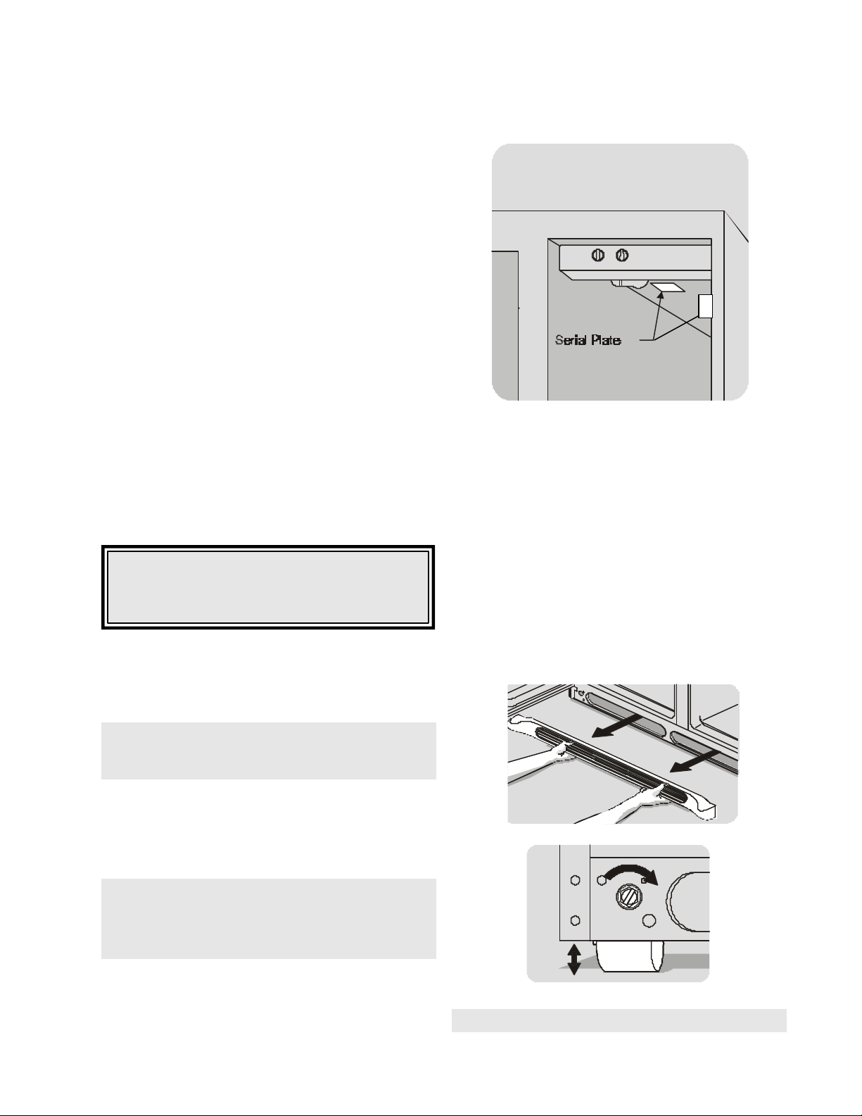
MODEL AND SERIAL NUMBER
Model and Serial Numbers are found on the Serial Plate
located on the ceiling of the refrigerator compartment,
just behind the compartment light, or on the right side at
the top (See Figure A1).
AIR CIRCULATION
Proper air circulation must be maintained for efficient
refrigerator operation. Refer to the Owner's Guide for
recommended clearances. Install the refrigerator out of
direct sunlight and away from the range, dishwasher, or
other heat sources.
CAUTION: Do not install the refrigerator where
the temperature will drop below 55°F (13°C), or
rise above 110°F (43°C) because the compressor
will not be able to maintain proper temperatures.
Allow an extra
back for ease of installation, proper air circulation, and
plumbing and electrical connections. If the hinge side of
the unit is placed against a wall, allow a ½" minimum
between hinges and wall to permit proper door swing.
3/8" on the top and sides, and 1" from the
Figure A1
LEVELING
The refrigerator must be leveled with all bottom corners
resting firmly on a solid floor. Adjust the front rollers to
level the cabinet from side-to-side and front-to-rear. Keep
the cabinet as low as possible for stability. Never adjust
the cabinet rollers so the front is lower than the rear.
To adjust the front rollers:
1. Open refrigerator and freezer doors.
2. Remove toe grille by pulling it straight out. (See Figure
A2.)
3. Adjust rollers by turning each roller adjusting bolt with
flat-blade screwdriver, adjustable wrench, 3/8" socket
wrench, or 3/8" nutdriver until refrigerator is level and
stable. (See Figure A3.)
NOTE: Do not block the toe grille on the lower front
of the refrigerator. Sufficient air circulation is
essential for proper operation of the refrigerator.
ELECTRICAL INFORMATION
The refrigerator must be plugged into a dedicated AC
only electrical outlet. The circuit should be protected by
a circuit breaker or time delay type fuse of the capacity
noted on the serial plate.
NOTE: If voltage varies by ±10% of supply voltage,
performance of the refrigerator may be affected.
Operating the refrigerator with insufficient power
can damage the compressor.
The refrigerator power cord is equipped with a three prong
grounding plug. It must be plugged directly into a properly
grounded three prong receptacle. The receptacle must be
installed in accordance with local codes and ordinances.
Do not use an extension cord or an adapter plug.
Figure A2
Raise
Figure A3
NOTE: Rear rollers are not adjustable.
6
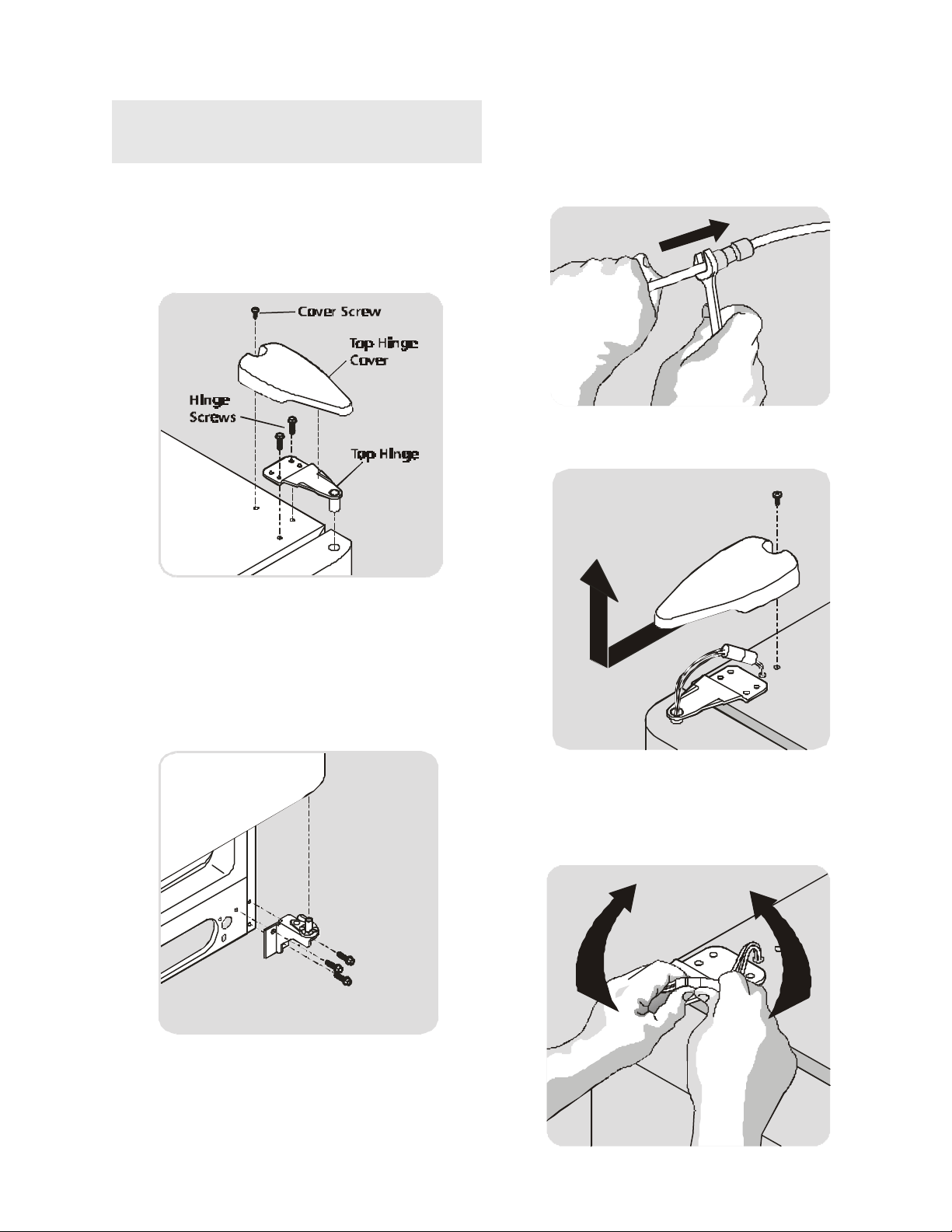
DOOR REMOVAL
NOTE: If installation requires the removal of the
doors, trace around all hinges with a soft lead pencil
for easy relocation.
1. Disconnect electrical supply.
2. Open both doors, then remove toe grille.
3. Close doors.
To Remove Refrigerator Door:
1. Remove top hinge cover screw. Remove cover.
To Remove Freezer Door:
1. Disconnect water line that goes through lower hinge
of freezer door at connection located under front of
freezer: grip water line firmly in one hand, then with
3/8" wrench or fingers, push in on gray collar to
release water connector.
2. Remove top hinge screw on freezer door, then
remove cover.
2. Trace around hinge with soft lead pencil. This will
make it easier to realign doors when they are replaced.
3. Remove top hinge.
4. Lift refrigerator door off bottom hinge pin. Set door
aside.
5. Remove bottom hinge, if necessary.
6. Reverse this procedure to reinstall refrigerator door.
3. Disconnect wiring harness connector plug at top
hinge: place your thumbs on flat sides of each
connector bending both sides back and forth, then
with form grasp, pull both pieces apart.
7
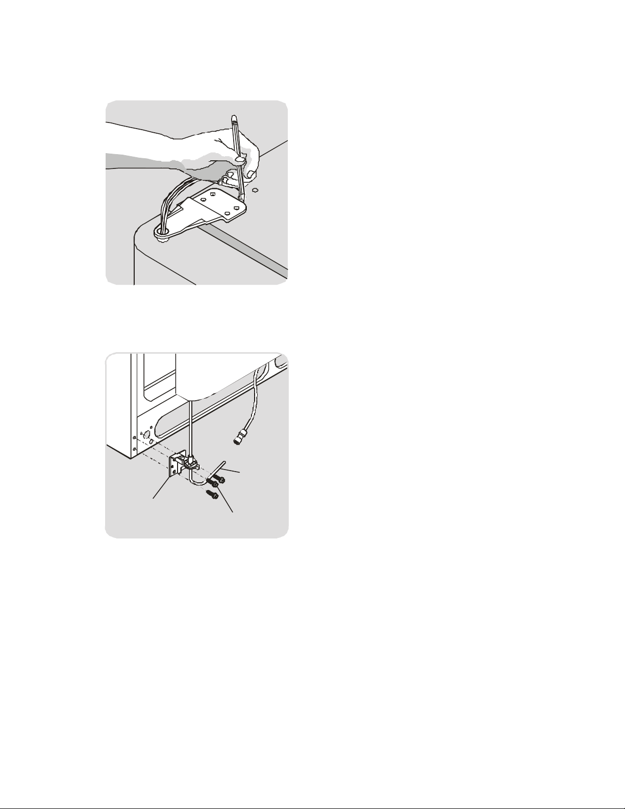
4. Trace around hinge with soft lead pencil. This will
make it easier to realign doors when they are
reinstalled.
5. Remove top hinge, allowing wiring harness to pull
through hinge.
6. Lift freezer door off bottom hinge pin. Lay door down
flat to avoid kinking water line.
Door
Water
Line
Tubing
Hinge
Assembly
Screws
7. Remove bottom hinge, if necessary.
8. Reverse this procedure to reinstall freezer door.
8
SECTION B - REFRIGERATOR CABINET
Washers
BASIC CONSTRUCTION
Next generation models have clean back cabinets and/or
forced air condensers. The condenser is located under
the cabinet bottom. The cabinet wrapper consists of a
one-piece top and sides formed of prepainted steel, with
an interlocking, snap-in, galvanized steel back panel. A
separate steel frame is attached to the cabinet bottom.
The compressor compartment houses the compressor,
condenser, and fan motor.
All cabinet seams have special sealing materials applied
as vapor barriers, prior to installation of the inner liner
and foam insulation.
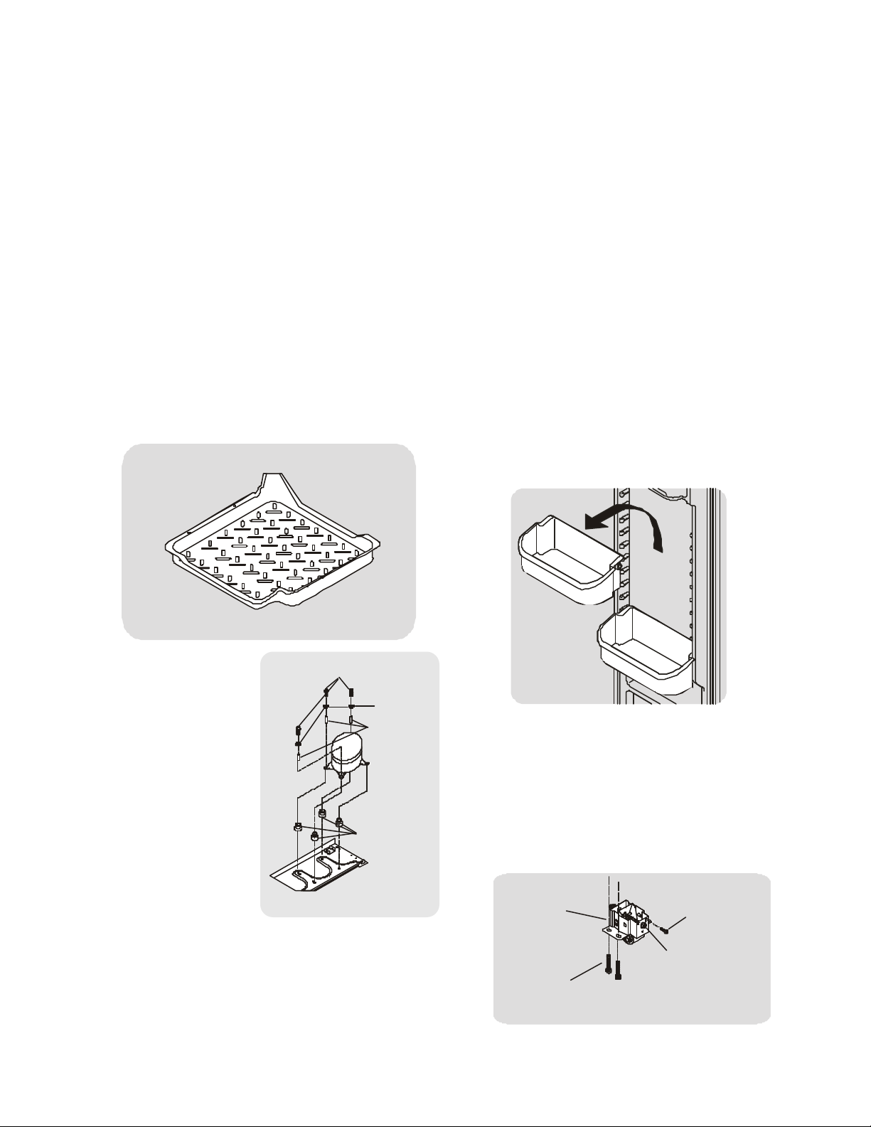
COMPRESSOR MOUNTING
All next generation models side by sides will have a
dynamic condenser and a unitary drain pan assembly
that is mounted to the bottom of the refrigerator cabinet
just behind the toe grille. (See Figure B1.)
Drain Pan
CABINET DOORS AND GASKETS
The exterior door panels are made from one piece of
heavy gauge, deep drawn, cold-rolled steel. A wide
flange at the periphery is formed integral with the exterior
door panel.
Next generation model doors are filled with rigid Urethane
foam insulation prior to assembly of the inner panel and
door gasket.
The door inner panels are vacuum formed from high
strength plastic.
Adjustable Door Bins
Some models have adjustable door bins that can be
moved to suit individual needs.
To move door bins:
1. Lift bin straight up.
2. Remove bin.
3. Place bin in desired position.
4. Lower bin onto supports until locked in place.
Figure B1
The compressor is
mounted on rubber
Shoulder Screws
grommets with metal
inserts, then bolted to
the base using four Hex
head,
14-28 shoulder
Inserts
screws. (See Figure B2)
INSULATION AND
INNER LINER
The cabinet wrapper and
compartment liner are
Rubber
Grommets
bonded together with a
core of "Urethane" foam
insulation to form a slim
Figure B2
three-ply wall of single-
unit construction.
The one piece freezer and the one piece food inner liners
are vacuum formed of tough corrosion-proof ABS/HIPS
plastic material. The liners are not removable.
Figure B3
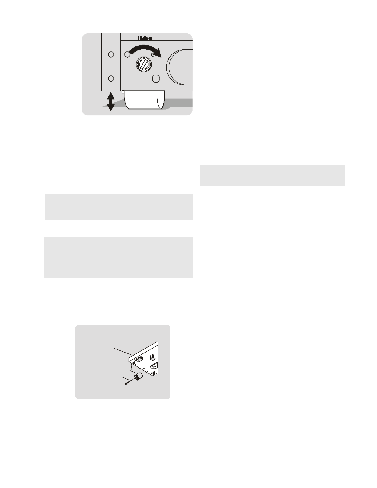
FRONT AND REAR ROLLERS
The front roller is mounted with two screws to the cabinet
base and one screw to the front of the cabinet. (See
Figure B4) The adjustment screw at the top of the roller
is turned clockwise to raise the cabinet, and counterclockwise to lower the cabinet (See Figure B5). While
making adjustments, slightly raise the cabinet to reduce
the strain on the roller assembly.
Roller
Assembly
Roller
Mounting
Bolts
Figure B4
Roller
Mounting
Screw
Roller
Adjusting
Bolt
9
Lacquer Refinishing
The following steps to touch-up or refinish a acrylic
painted cabinet, except in gasket contact areas.
Figure
B5
To Remove Front Roller Assembly:
1. Disconnect refrigerator from electrical power.
2. Raise and support cabinet.
3. Remove two bolts securing roller to bottom of
refrigerator.
4. Remove one screw securing roller to front of cabinet.
Roller should fall free.
5. Reassemble in reverse order.
To Remove Rear Roller: (See Figure B6)
NOTE: The rear roller assembly is mounted to the
bottom of the compressor base. Raise and support
cabinet before removing rear roller.
1. Disconnect refrigerator from electrical power.
2. Raise and support cabinet.
NOTE: The end of the roller pin that protrudes
through the roller has been flared to prevent it from
slipping out. You will have to squeeze it back
together with a pair of pliers before it will slide out for
removal.
3. Squeeze flared end of roller pin together using pair
of pliers.
4. Pull roller pinfree of roller and compressor base.
Roller should fall free. If not, you may have to tap roller
lightly with hammer to free it from compressor base.
5. Reassemble in reverse order.
Figure B6
Compressor Base
Roller
Roller Pin
CABINET TOUCH-UP PROCEDURE
Vinyl gaskets are used on all models. Lacquer repairs
can be made on all areas of the cabinet except any
painted surface that comes in contact with the vinyl
gasket. Since prolonged contact of vinyl gaskets with
lacquer will soften the lacquer, repairs in these areas
should not be attempted.
1. Sand out spot to be repaired with 360 or 400 wet-ordry sandpaper. Finish sanding to feather edge with
600 wet-or-dry sandpaper. Wipe area dry. Hand rub
with fine rubbing compound (Dupont VZ1090
®
or
equivalent), the area extending at least six inches
beyond edges of lacquer repair spot. Wipe compound off and wash area with Naphtha. Dry with
clean cloth.
®
2. Prepare bare metal with Sol-Kleen
cleaner and
rust remover. Reduce cleaner with two parts
water, and apply with a clean wet rag. Do not
touch painted surface with this cleaner. Stubborn or
deep seated rust can be removed by applying
cleaner with steel wool.
NOTE: Prepare surface of bare metal with
®
Sol-Kleen
regardless if rust is present.
3. Before cleaner dries, wipe surface dry with clean
rag.
4. Wipe over surface thoroughly second time with
solution of 50-50 alcohol and water. Wipe again
with clean dry rags, preferably new cheesecloth.
5. Allow to dry for at least 10 to 15 minutes.
6. Apply primer surfacer, reduced by approximately
equal parts of lacquer thinner, to build bare metal
area up to surrounding surface. Any imperfections
which primer has not filled should be knifed out with
lacquer type putty glaze.
7. If no putty glaze is used, allow to dry about 30
minutes and, if necessary, sand out lightly with 360
wet-or-dry sandpaper. If putty glaze is used, allow
about three hours before sanding with sandpaper
and water. Remove sanding residue thoroughly by
wiping with clean rag soaked in naphtha. Wiping
surface with tack rag will remove dust and lint.
8. Finish repair with two or more coats of lacquer
(reduce approximately one part of lacquer to 1½
parts of thinner). Finally, apply mist coat of
lacquer thinner to flow out surface.
9. Patched area should be allowed to dry three or more
hours before rubbing with compound or polish.
This procedure also applies to the complete refinishing
of the cabinet, except gasket contact areas. All
damaged areas should be repaired as outlined in steps
1 through 6 above. The overall surface of the cabinet
should be sanded thoroughly and cleaned as outlined in
step 7.
The cabinet should be given two or more coats of touchup lacquer and polished as outlined in steps 8 and 9.
10
SECTION C - ELECTRICAL COMPONENTS
ELECTRICAL GROUNDING
All refrigerators are equipped with a power supply cord
incorporating a three-prong grounding plug and a ground
wire which is attached to the refrigerator cabinet for
protection against shock hazard. Each electrical component is either cabinet mounted or connected through
a ground wire to the cabinet to complete the ground.
Certain components, such as defrost timers, may be
double insulated and do not require a ground wire.
Ensure the electrical wall receptacle is of the three prong
type and is properly grounded in accordance with the
National Electrical Code and/or local codes.
COMPRESSOR
ELECTRICAL COMPONENTS AND CIRCUITS
The new series of very high efficiency compressor is
equipped with all new electrical components consisting
of a solid state PTC relay with a thermally operated
overload protector, and a run capacitor.
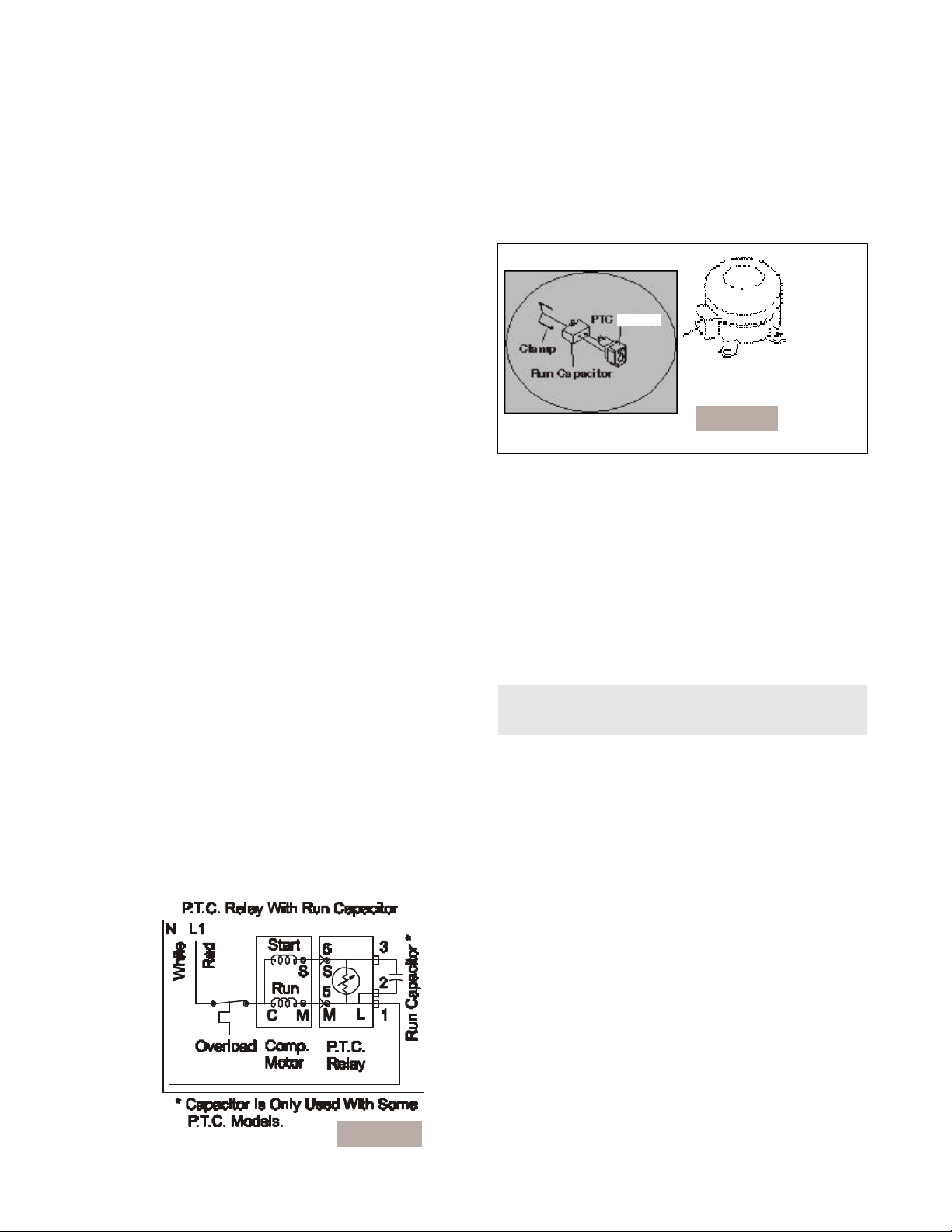
Solid State Relay
The solid state relay has no moving parts. It consists of
a PTC resistor mounted in a plastic case with
appropriate terminals. PTC (Positive Temperature
Coefficient) simply denotes a resistor which increases
in resistance as its temperature is increased. The selfheating PTC resistor used in the solid state relay has the
unique characteristic of changing from low to very high
resistance very abruptly, thus serving as an on-off
switch (See Figure C1).
The solid state relay plugs directly onto the compressor
start and run terminals. Relay terminals 1, 2, and 5 are
connected within the relay, as are terminals 3 and 6.
A run capacitor is connected to relay terminals 2 and 3,
so it is connected in parallel with the PTC resistor. One
side of the input power is connected to relay terminal 1.
The other side of line is connected to the overload
protector. (See figure C1)
Figure C1
To Check/Replace Relay
1. Disconnect electrical supply to refrigerator.
2. Remove clamp holding relay to compressor.
3. Remove relay assembly from compressor.
(See Figure C2)
Relay
Figure C2
4. Use small, flat-bladed screwdriver to disconnect
leads to relay assembly.
5. Use flat headed screwdriver to gently pry capacitor
from relay assembly.
6. Use ohmmeter to check resistance between
terminals 5 and 6. Resistance should be 3 to 12
ohms, at normal room temperature. Shorted relay
will read 0 ohms. Open relay will read very high or
infinite resistance.
7. If ohm readings are out of range, replace relay.
8. Reverse this procedure to re-assemble.
NOTE: When replacing leads to the PTC relay,
ensure locking tabs snap into terminal.
Overload Protector
The overload protector is completely thermally operated. It will open from excessive heat or current. Unlike
prior overloads, the internal bi-metal is not self-heating,
and is not a part of the electrical circuit. The overload has
a small built-in coil heater that is in series with the
compressor start and run windings (See Figure C1).
To Check/Replace The Overload Protector
1. Disconnect electrical supply to refrigerator.
2. Remove clamp holding relay to compressor.
3. Remove relay assembly from compressor.
4. Use flat headed screwdriver to gently pry capacitor
from relay assembly.
5. Use small, flat-bladed screwdriver to disconnect
leads to relay assembly. (Note: On some models you
will have to remove clamp and cover, to gain
access to relay and overload protector.)
6. Use ohmmeter to check resistance between tab
terminal and female pin terminal. Overload protector
should have less than 1 ohm of resistance at normal
room temperature.
11
7. If ohm readings are out of range, install new
Starter/Overload Assembly.
NOTE: The Overload Protector is built into the
Starter Overload Assembly. It cannot be read
independently from the Starter.
8. Reverse this procedure to re-assemble.
NOTE: When replacing leads to the PTC Relay,
ensure the locking tabs snap back into the terminal.
Run Capacitor
The run capacitor has permanently attached terminals
which are connected to relay terminals 2 and 3.
NOTE: Some models are not equipped with a Run
capacitor
To Check/Replace The Run Capacitor
1. Disconnect electrical supply to refrigerator.
2. Remove bale wire holding relay to compressor.
2. Use small, flat-bladed screwdriver to disconnect
leads to relay assembly.
3. Use flat-bladed screwdriver and gently pry
capacitor from relay assembly.
4. Discharge capacitor by shorting across terminals
with 500K (1 watt) resistor for one minute.
5. Use ohmmeter set on the “Ohms times 1000”
scale (if available), to check resistance across
capacitor wire terminals.
Figure C3
Compressor Run Circuit
When the self-heating solid state relay has reached
sufficient temperature, it will abruptly change from low
resistance (3-12 ohms) to very high resistance (10-20K
ohms) and, in effect, switches off the start windings.
The relay no longer shunts the run capacitor. The run
capacitor is now in series with the start windings. The
only purpose of the run capacitor is to improve
compressor operating efficiency, which it does by correcting the power factor of the compressor motor (See
Figure C4).
• The needle should jump towards zero ohms
and quickly move back to infinity.
• If the needle does not move, the capacitor is
open.
• If the needle reads a constant value at or near
zero ohms, the capacitor is shorted out.
• If the needle jumps toward zero and then
moves back to constant high resistance (not
infinity), the capacitor has a high resistance
leak.
6. If ohm readings are out of range, replace capacitor.
7. Reverse procedures to re-assemble.
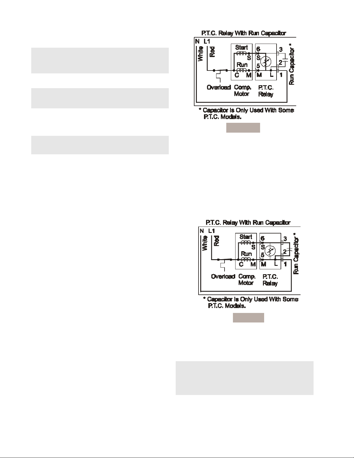
Compressor Start Circuit
When the compressor circuit is first energized, the solid
state relay has low resistance (3-12 ohms), and both the
run and start windings are energized to start the
compressor. The run capacitor1 is being bypassed by
the relay, and it has a minor function during compressor
starting (See Figure C3).
Figure C4
COMPRESSOR OPERATING CHARACTERISTICS
• When the compressor electrical circuit is energized,
the start winding current causes the relay to heat
and switch off the start winding circuit.
NOTE: The relay will switch off the start winding
circuit even though the compressor has not started
(as when attempting to re-start after momentary
power interruption).
• The overload protector is designed and calibrated
to open the compressor electrical circuit with locked
rotor run winding current only.
12
• With an open relay, the compressor will not start
since there is little or no current to the start windings.
The overload protector will open due to high locked
rotor run winding current.
• With a shorted relay or capacitor, the compressor
will start, and the overload protector will open.
• With an open or weak capacitor, the compressor will
start and run.but it will use more energy.
COMPRESSOR ELECTRICAL CHECK
If the compressor will not run, make a voltage check
across the power lead terminals on the PTC Relay. (See
Figure C4.)
The voltmeter should show line voltage if the thermostat
knob is in normal operating position and not in the OFF
position. If this check does not show a live circuit, the
control thermostat and defrost timer wiring should be
checked for loose or broken connections.
A control thermostat check can be made by using a
piece of wire as a temporary bridge across two thermostat terminals. If the compressor starts and runs with the
bridge, the control thermostat is at fault and should be
replaced.
If a voltage check shows power supply at the PTC Relay
terminals, use a test cord to check the compressor.
If the compressor does not start and run with the test
cord, check the line voltage to see if there is more than
10% variation from the rated voltage. If the voltage is
correct and the compressor will not start and run, replace
the compressor.
If the compressor starts and runs with the test cord,
replace the PTC Relay.
To Remove Evaporator Fan Motor
1. Disconnect refrigerator from electrical supply.
2. Remove freezer section bottom shelves and
baskets.
3. Remove ice container and rail assembly.
Multiconnector at back of rail assembly must be
disconnected before rail assembly will come free.
4. Loosen 2 screws holding ice maker to right side
of compartment just enough to lift ice maker free.
Multiconnector must be disconnected before ice
maker will come free from compartment.
5. Remove two rail assembly supports. (two screws on
each one).
6. Remove four screws from evaporator cover.
7. Remove five screws on evaporator air duct cover.
8. Disconnect connector and green ground lead
connected to evaporator fan motor. Evaporator fan
motor assembly can now be pulled free.
9. Remove two screws holding fan motor bracket to
shroud.
10.Remove fan blade and slinger washer.
11.Remove two screws holding front and rear motor
brackets together. Pull evaporator fan motor free.
12.Reverse procedure to complete repairs.
NOTE: The Slinger washer on the fan motor shaft
must be adjusted to within 1/16” to 1/8” from the
motor to prevent water from entering the motor
bearing.
NOTE: When replacing the fan blade, press the
blade onto the motor shaft until the blade bottoms
out on the shaft.
PERIMETER AND MULLION HOT TUBE
To reduce the possibility of condensation forming on the
exterior of the cabinet in high humidity areas, units are
equipped with a one piece perimeter and mullion hot tube
which is part of the refrigeration system. No electric
heaters are used. Refer to the Refrigeration Section for
more information.
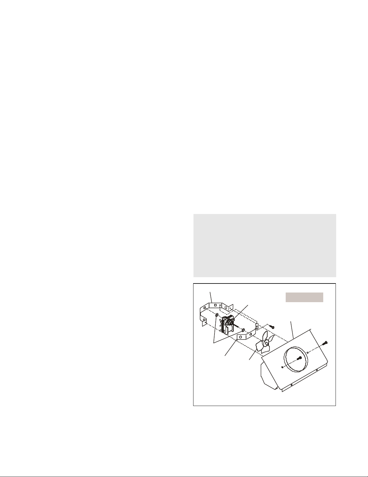
EVAPORATOR FAN & MOTOR ASSEMBLY
The fan and motor assembly are located behind the
freezer compartment air duct directly above the
evaporator in the freezer compartment.
The fan is a suction type, pulling air up through the
evaporator and blowing it through the refrigerator compartment fan grille.
On current production models, the fan blade is not
adjustable and is designed to be pressed onto the motor
shaft until it bottoms out against the stop at the front of
the fan blade.
13
Rear Bracket
Bushings
Evaporator
Fan Motor
Shroud, Fan Orifice
Front Bracket
Fan Blade
Evaporator Fan Motor Assembly
Figure C5
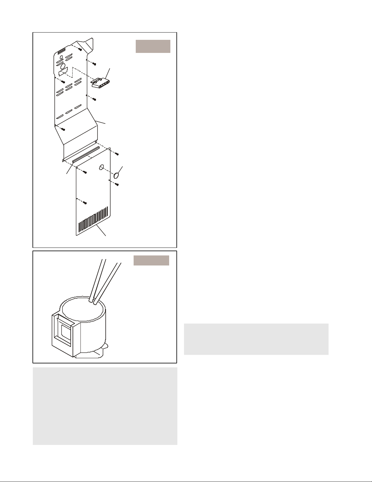
Figure C6
Ice Maker Duct
Air Duct Cover
Hole Plug
Seal
Evaporator Cover
Figure C7
Defrost
Thermostat
NOTE: An experienced serviceman may choose
not to remove the Ice Maker, bucket and rail
assembly when removing the evaporator, defrost
thermostat or defrost heater. Through experience,
he has learned that only the bottom two screws on
the air duct cover need to be removed once the
evaporator cover has been removed. This allows
the air duct cover to be pulled forward enough to
slide the drain trough out enough to remove the
evaporator.
DEFROST THERMOSTAT
The defrost thermostat is a temperature sensing device.
Wired in series with the defrost timer and the evaporator
defrost heater, it senses the rise in evaporator
temperature during a defrost cycle and cycles the
defrost heater off after all frost is melted. It is calibrated
to permit a defrost cycle only when the temperature is
below a preset temperature. The contacts in the defrost
thermostat are set to open at 47°F and close at 25°F.
To Test Defrost Thermostat
1. Measure resistance across two thermostat leads at
connector plug. At room temperature, resistance
should be infinity. The contacts are open.
2. Place a couple ice cubes on sides of thermostat.
After a few seconds, thermostat should reset.
3. Measure resistance again. This time, reading
should be 0. Contacts have closed.
4. If you get resistence readings that differ from the
readings in this procedure, replace defrost
thermostat. Contacts are probably burnt.
To Remove Defrost Thermostat
1. Disconnect refrigerator from electrical supply.
2. Remove freezer section bottom shelves and baskets.
3. Remove ice container and rail assembly.
Multiconnector at back of rail assembly must be
disconnected before rail assembly will come free.
4. Loosen two screws holding ice maker to right side
of compartment, just enough to lift ice maker free.
Multiconnector must be disconnected before ice
maker will come free from compartment.
5. Remove two rail assembly supports. (two screws per
support).
6. Remove four screws from evaporator cover.
7. Remove five screws on evaporator air duct cover.
8. Cut two leads coming from thermostat close to base.
You must leave enough wire coming from connector
to allow for splicing new thermostat.
9. Remove faulty thermostat.
NOTE: The Defrost Thermostat Replacement Kit
comes with a new thermostat, two solderless
connectors and two pieces of heat shrink to allow for
splicing the new thermostat to the connector plug.
10.Crimp two solderless connectors to two leads on new
thermostat.
11.Slip two pieces of heat shrink onto two leads coming
from connector plug.
12.Crimp two solderless connectors to two leads coming
from connector plug.
13.Slip heat shrink over solderless connectors and heat
that area with heat gun until heat shrink is tight around
solderless connectors.
14.Hook thermostat back on evaporator near or at same
place it was before.
15. Reverse Steps 1 - 7 to complete repairs.
14
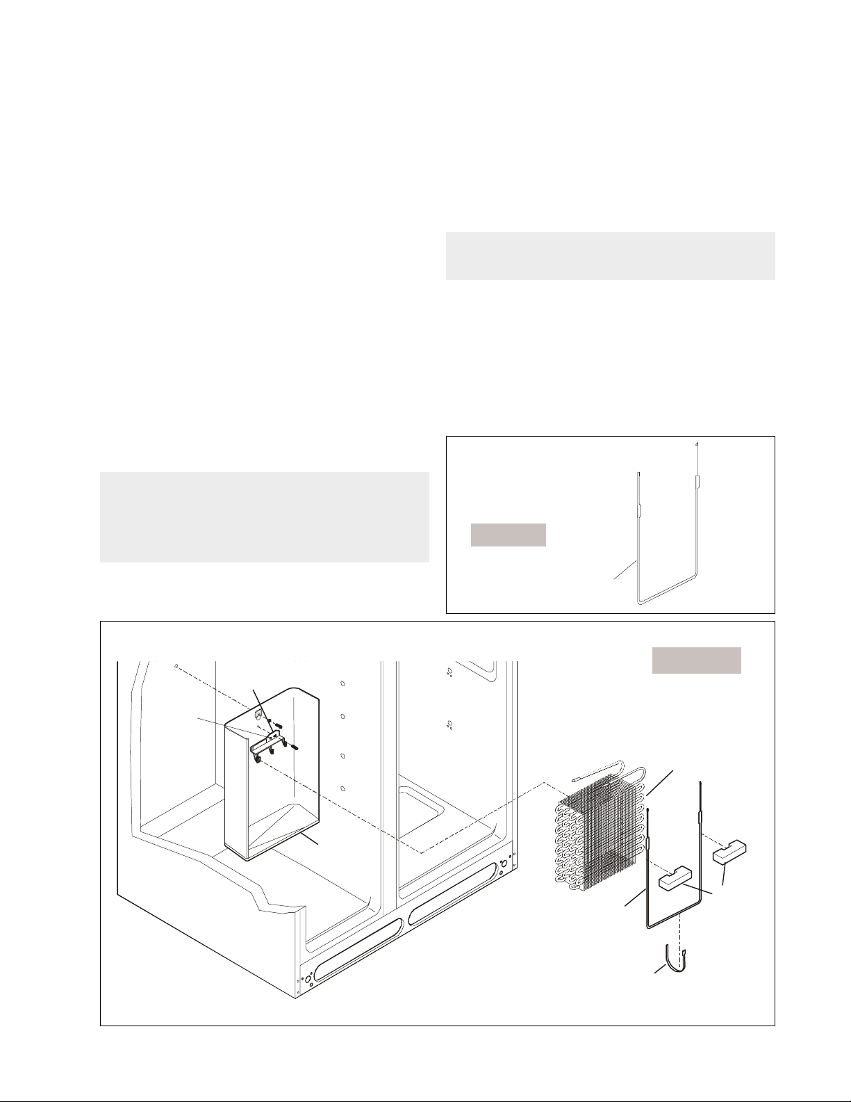
DEFROST HEATER
The defrost heater is a radiant “U” shaped resistance
heater, rated at 450 watts. The defrost heater is energized
during that period of the cycle when the defrost thermostat
contacts are closed.
The length of time the heater is energized depends on
the amount of frost accumulation on the evaporator.
How To Remove The Defrost Heater
1. Disconnect refrigerator from electrical supply.
2. Remove freezer section bottom shelves and baskets.
3. Remove ice container and rail assembly.
Multiconnector at back of rail assembly must be
disconnected before rail assembly will come free.
4. Loosen two screws holding ice maker to right side
of compartment, just enough to lift ice maker free.
Multiconnector must be disconnected before ice
maker will come free from compartment.
5. Remove two rail assembly supports. (two screws per
support).
6. Remove four screws from evaporator cover.
7. Remove five screws on evaporator air duct cover.
8. Disconnect two leads to defrost heater.
NOTE:This is a good time to test the heater. Check
resistance of defrost heater using a multimeter.
Resistance should be very close to 30 ohms.
Replace defrost heater if resistance readings are
out of range.
9. Unclip ground wire hooked to drain trough.
10.Remove screw holding evaporator bracket (through
drain trough) to cabinet.
11.Remove rivet (must be drilled out) holding evaporator
bracket to drain trough.
12.Remove screw holding drain trough to cabinet .
13.Lift up and out on drain trough, pulling forward enough
to allow enough room to slide drain trough free of
evaporator.
NOTE: Use caution not to damage the suction line
and cap tube.
14.Slide drain trough straight out and off evaporator.
15.Remove retainer clamp (aluminum strap) that
secures defrost heater to bottom of evaporator.
16.Grab heater from bottom and pull free of
evaporator. It’s very snug so you’ll need to use a
little force.
17.Replace with new defrost heater.
18.Re-assemble in reverse order.
Figure C8
Rivot
Evaporator Bracket
Drain T rough
Defrost H eater
Defrost
Heater
Figure C9
Evaporator
Styrofoam
Blocks
Strap
15
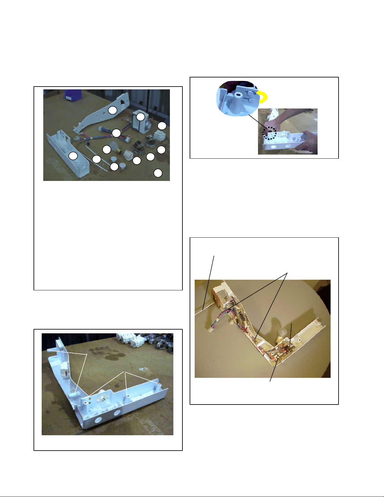
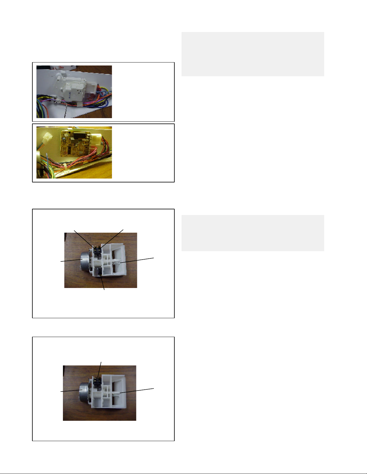
CONTROL SYSTEM
The Freezer and Refrigerator controls are located in the
same housing, mounted in the food compartment along
with the light and defrost timer or Automatic Defrost
Control (ADC). See Figure 1.
2
4
11
3
1
7
5
6
8
10
9
12
1. Control Box - Front Section
2. Control Box - Rear Section
3. Control Wiring Harness
4. Food Compartment Damper Control
5. 2 Plastic Tubes (Cover Control Bulb)
6. 2 Knobs for Controls
7. Light Bulb
8. Socket - Light Bulb
9. Cold Control - Food Compartment
10. Cold Control - Freezer Compartment
11. Defrost Timer/ADC Control
12. 2 Wire Retainer Clips (not shown)
The housing assembly will separate at left back of front
section by sliding rear section to right until buttons line
up with larger hole in slots. (See Figure 3.)
Figure 3
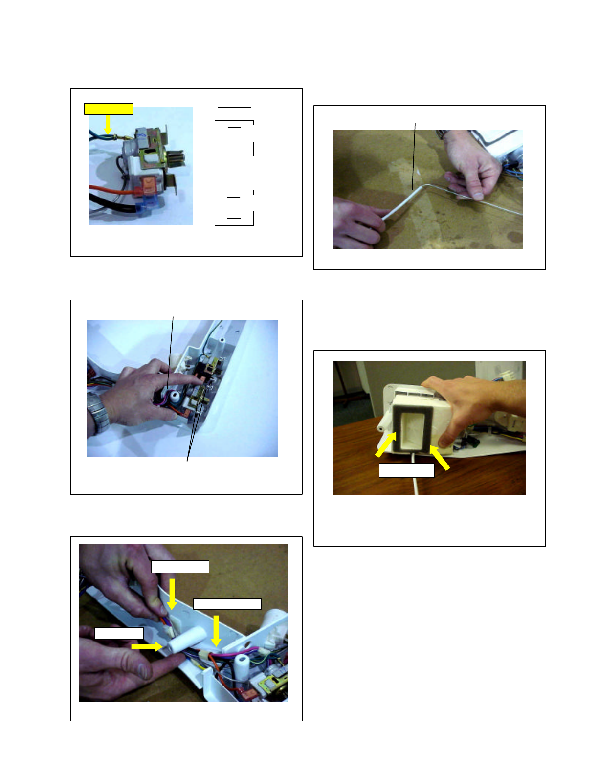
Freezer Compartment Control
The Freezer Control is mounted on the left (as shown in
Figure 4) and it controls the cycling of the compressor
and fan motors. The cap tube for the control runs along
the right side of the rear housing and has a plastic sleeve
installed on the last eight inches.
To replace Freezer Control, remove screws and drop
housing. Pull cap tube for control from guide tube under
air inlet at back of rear housing. (See figure 4.)
Cap Tube Freezer Control
with Plastic Tube
Runs along rear housing
and out under Damper
Control
Figure 1
To remove the Control Housing Assembly, remove the
three screws across the front control box and the two
screws located in the rear control box. (See Figure 2.)
Rear Screws
Front Screws
Figure 2
Food
Compartment
Control
Freezer Control
Figure 4
16
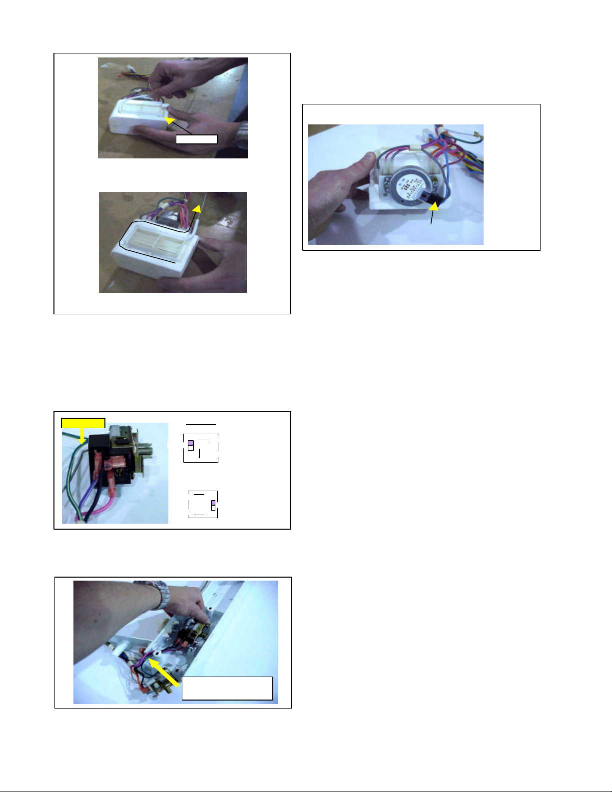
To install new Freezer Control, connect wires as shown
l
(White)
btm-blk
Invensys
(Green)
through wireway
in Figure 5; ground wire (green) must be attached as
well.
Ground Wire
GE Contro
top-orange
(or blue)
top-orange
(or blue)
btm-blk
Figure 5
After wires are connected, snap control into place and
route wires around screw boss. (See Figure 6.)
Place wires around screw boss.
Snaps wires and capillary tube into clip behind defrost
control. Place plastic tube over end of control cap tube
until it is even with end of tube. Make 90° bend in tube at
end of plastic sleeve. (See Figure 8.)
Install plastic tube over control cap tube.
Figure 8
Tape freezer cap tube to damper control and install
damper into rear control box. (See Figure 9.) Slide end
of cap tube in slot under air duct, which runs from freezer
to fresh food compartment, until seal on damper
housing contacts liner. Install screws to hold control
housing in place.
Snap in place.
Figure 6
Route wire harness and capillary tube through wire-way,
under boss screw, and snap into clip as shown in Figure
7.
snap into clip
under boss
Figure 7
PUSH here
Tape control cap tube to bottom of damper
control. Push control into housing.
Figure 9
Fresh Food Compartment Control
The Fresh Food Compartment Control is located on the
right side on the front control section. The cap tube for
the control runs alongside the freezer cap tube back to
the damper control. Like the freezer control, the last 8
inches is covered with a plastic sleeve. The end of the
cap tube with the sleeve is snapped into a channel in
the air diffuser in front of the damper control. (See Figure
10.) The Fresh Food Compartment Control will have an
OFF position for the servicer to use in testing, but the
word “OFF” will not show on the dial plate. To turn the
control OFF, turn knob counterclockwise past WARM to
the straight down position and you will feel the OFF
position.
17
l
1-pink
Start here
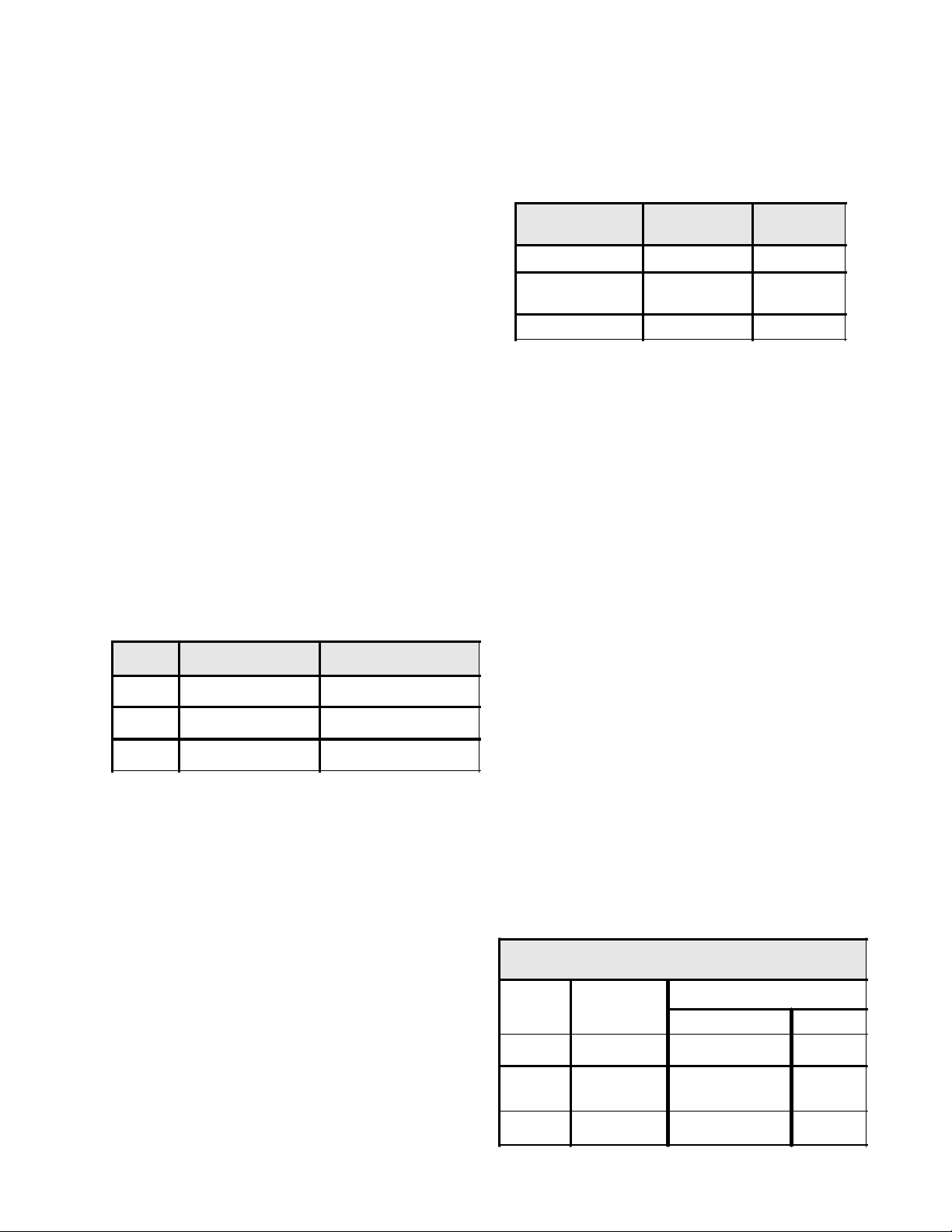
Air Damper Control
The air damper is used to control the fresh food
compartment temperature by controlling air flow into the
food compartment from the freezer. (See Figure 13.)
Damper Control
Press cap tube with plastic shield
in channel on diffuser.
Figure 10
When the control is off, the damper should close and
the fan should shut off, if the compressor is not running.
To replace Fresh Food Compartment Control, remove
screw and drop housing (follow freezer control
instructions). Snap control out of housing, then remove
damper control and cap tube for control. Connect wiring
to new control as shown in Figure 11.
3-p/w
top-pink
btm-blk
GE Contro
(Brown)
Invensys
(Orange)
2-blk
Figure 11
p/w
Ground Wire
Place control metal wing in solid clip first, then snap
other side in place. Route wires and cap tube behind
boss. (See Figure 12.)
Figure 12
Figure 13
When the food compartment control calls for cooling,
the contacts in the control will open from 2 to 3 and
close from 2 to 1. This will start the damper motor running,
open the damper, and start the freezer compartment
fan running. (See Figure 14.)
As the damper motor opens the damper, the switches
on the damper will change from NO (normally open) to
the NC (normally closed) position one at a time to prevent
the stopping of the motor in a 1/2 open position, as a
result of a power outage as the damper is opening or
closing. When both switches have reached the NC
position, the damper will be all the way open and the
motor will stop. (See Figure 15.)
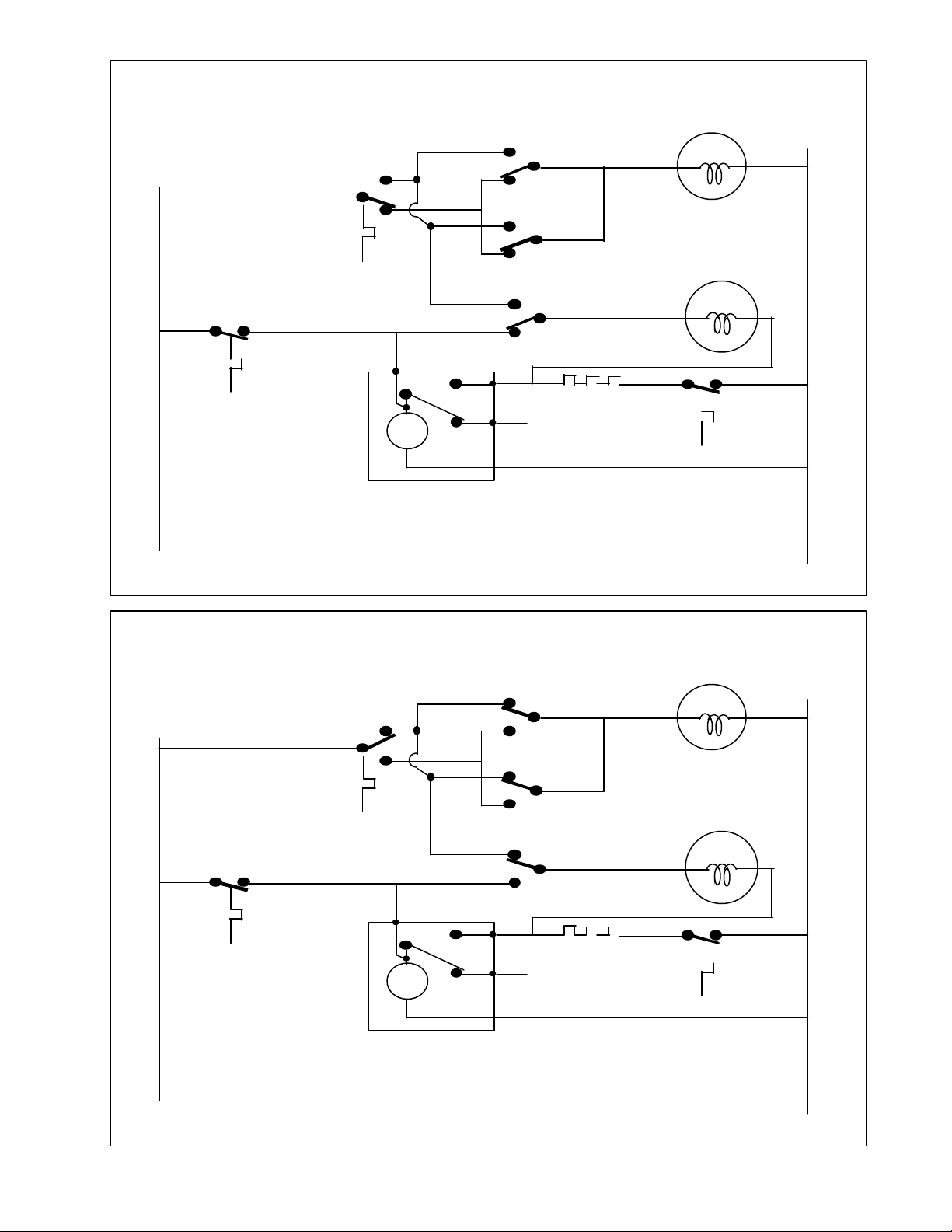
The damper will remain open and the fan motor will
continue to run as long as the food compartment control
calls for cooling. Once the food compartment control is
satisfied, the contacts in the cold control will open from
2 to 1 and close from 2 to 3. This will start the damper
motor running again, closing the damper and shutting
off the freezer fan motor. (See Figure 16.)
As the damper motor closes the damper, the switches
on the damper will change from the NC to the NO position
one at a time. When both switches have reached the NO
position, the damper will be all the way closed and the
motor will stop. (See Figure 17.)
There are two types of damper controls. One has 3
switches; two at the top for the damper motor and one at
the bottom to control the freezer fan motor. This type is
used on models with a defrost timer.
The other type has two switches at the top only and is
used on models with an Adaptive Defrost Control (ADC).
(See Figure 23.)
Route wires & cap
tube behind boss
Place the air damper in the housing and reinstall housing
in the fresh food compartment.
18
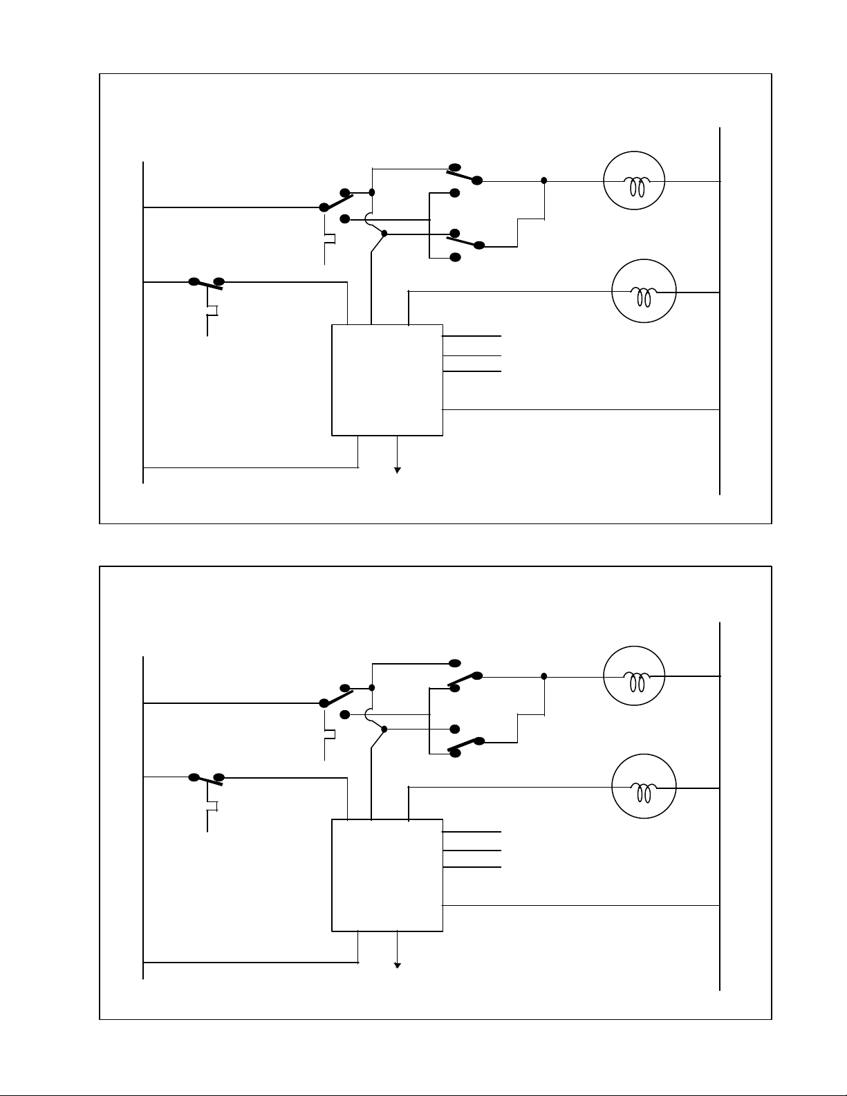
L1
FOOD COMPARTMENT CONTROL CALLS FOR COOLING
DAMPER MOTOR STARTS RUNNING TO OPEN DAMPER
DAMPER MOTOR
REFRIGERATOR
CONTROL
FRONT SWITCH
NO
1
NC
C
N
FREEZER CONTROL
21
A.D.C. ADAPTIVE
DEFROST CONTROL
L1
2
3
NO
NC
C
BACK SWITCH
E2
E8
E6
A.D.C.
E7
E9
E1
E5
E3
E4
TO DEFROST HEATER
TO DEFROST THERMOSTAT
TO COMPRESSOR
NOTE: SWITCHES WILL CLOSE AND
OPEN ONE AT A TIME TO PREVENT
STALLING IN A HALF OPEN POSITION
AS A RESULT OF A POWER OUTAGE
TO FOOD COMPARTMENT LIGHT SWITCH
FIGURE 14
FOOD COMPARTMENT CONTROL IN ON POSITION
DAMPER OPEN ALL THE WAY
FRONT SWITCH
REFRIGERATOR
CONTROL
1
NO
NC
C
EVAP. FAN MOTOR
N
DAMPER MOTOR
FREEZER CONTROL
1
2
A.D.C. ADAPTIVE
DEFROST CONTROL
2
3
NO
NC
C
BACK SWITCH
E2
E6
A.D.C.
E9
E1
E5
E3
TO DEFROST HEATER
TO DEFROST THERMOSTAT
TO COMPRESSOR
E4
E8
E7
NOTE: SWITCHES WILL CLOSE AND
OPEN ONE AT A TIME TO PREVENT
STALLING IN A HALF OPEN POSITION
AS A RESULT OF A POWER OUTAGE
TO FOOD COMPARTMENT LIGHT SWITCH
FIGURE 15
19
EVAP. FAN MOTOR

L1
FOOD COMPARTMENT CONTROL IS SATISFIED
DAMPER MOTOR STARTS RUNNING TO CLOSE DAMPER
DAMPER MOTOR
REFRIGERATOR
CONTROL
FRONT SWITCH
NO
1
NC
C
N
FREEZER CONTROL
21
A.D.C. ADAPTIVE
DEFROST CONTROL
L1
2
3
NO
NC
C
BACK SWITCH
E2
E6
A.D.C.
E9
E1
E5
E3
TO DEFROST HEATER
TO DEFROST THERMOSTAT
TO COMPRESSOR
E4
E8
E7
NOTE: SWITCHES WILL CLOSE AND
OPEN ONE AT A TIME TO PREVENT
STALLING IN A HALF OPEN POSITION
AS A RESULT OF A POWER OUTAGE
TO FOOD COMPARTMENT LIGHT SWITCH
FIGURE 16
FOOD COMPARTMENT CONTROL IN OFF POSITION
DAMPER CLOSED ALL THE WAY
FRONT SWITCH
REFRIGERATOR
CONTROL
1
NO
NC
C
EVAP. FAN MOTOR
N
DAMPER MOTOR
FREEZER CONTROL
1
2
A.D.C. ADAPTIVE
DEFROST CONTROL
2
3
NO
C
NC
BACK SWITCH
E2
E6
A.D.C.
E9
E1
E5
E3
TO DEFROST HEATER
TO DEFROST THERMOSTAT
TO COMPRESSOR
E4
E8
E7
NOTE: SWITCHES WILL CLOSE AND
OPEN ONE AT A TIME TO PREVENT
STALLING IN A HALF OPEN POSITION
AS A RESULT OF A POWER OUTAGE
TO FOOD COMPARTMENT LIGHT SWITCH
FIGURE 17
20
EVAP. FAN MOTOR
L1
FOOD COMPARTMENT CONTROL IN OFF POSITION
DAMPER CLOSED ALL THE WAY
TOP SWITCH BY DAMPER
REFRIGERATOR
CONTROL
1
NO
NC
C
DAMPER MOTOR
N
FREEZER CONTROL
1
2
REFRIGERATOR
CONTROL
L1
2
3
NO
NC
C
BOTTOM SWITCH
NO
NC
C
TOP SWITCH BY MOTOR
1
2
TM
DEFROST HEATER
TO COMPRESSOR
4
3
MECHANICAL TIMER
NOTE: SWITCHES WILL CLOSE AND
OPEN ONE AT A TIME TO PREVENT
STALLING IN A HALF OPEN POSITION
AS A RESULT OF A POWER OUTAGE
FIGURE 18
FOOD COMPARTMENT CONTROL IN ON POSITION
DAMPER OPEN ALL THE WAY
TOP SWITCH BY DAMPER
DAMPER MOTOR
NO
1
NC
C
EVAP. FAN MOTOR
DEFROST
THERMO.
N
FREEZER CONTROL
1
2
2
3
BOTTOM SWITCH
TOP SWITCH BY MOTOR
1
2
TM
4
3
MECHANICAL TIMER
FIGURE 19
21
NO
NC
C
NO
NC
C
DEFROST HEATER
TO COMPRESSOR
NOTE: SWITCHES WILL CLOSE AND
OPEN ONE AT A TIME TO PREVENT
STALLING IN A HALF OPEN POSITION
AS A RESULT OF A POWER OUTAGE
EVAP. FAN MOTOR
DEFROST
THERMO.
Defrost Control
Two types of defrost controls are used; a timer system
(See Figure 20) and an Adaptive Defrost Control (ADC)
(See figure 21).
Figure 20
Figure 21
Note: Defrost interval timing is based on accumu-
lated compressor run time for all 115 volt units, and
is based on elapsed clock time for all 220 volt units,
whether a mechanical timer or ADC is used.
The mechanical timer is a standard 8 hour timer that will
shut off the compressor and allow the refrigerator to go
into defrost. On 115 volt units, the timer motor will only
advance when the compressor is running. On 220 volt
units, the timer motor will run continuously. In either
case, when the timer motor has run for 8 hours, the
compressor will shut off and the unit will go into defrost.
On mechanical timer models, the two switches closest
to the damper are connected to the damper motor. The
bottom switch is connected to the freezer fan motor. When
the food compartment control is in the OFF position and
the damper is closed all the way, the fan motor is
connected to the freezer control by the bottom switch.
(See Figure 18.)
On models with a mechanical timer, the evaporator fan
motor is controlled by a third switch mounted on the
damper control. (See Figure 22.)
Damper Control for Timer Models
Fan Motor Switch
Damper
Motor
Damper Switch
(Bottom Switch)
On models with an ADC, the evaporator fan is controlled
by the defrost control. (See Figure 23.)
Damper Control for ADC Models
Damper Motor Switches
(Top Switches)
Damper Motor Switch
Damper
Figure 22
When the food compartment control is in the ON position
and the damper is open all the way, the fan motor is
connected to the food compartment control and the fan
will start running. (See Figure 19.)
NOTE: On mechanical timer models, the evaporator fan motor will not start running until the defrost
terminator switch resets. (See Figures 18 and 19.)
The fan can be activated by either the food compartment
control or the freezer compartment control. If the food
compartment is calling for cooling and the fan is running,
then if the freezer control contacts close, the compressor
and the condenser fan motor will start. Once the food
compartment control is satisfied, the damper will close.
This will connect the fan motor to the freezer control.
The fan motor will continue to run until the freezer control
is satisfied and the unit shuts off. This is accomplished
by the switch closest to the motor. (See Figure 22.) When
the damper is open, the fan is connected to the food
compartment control.
On models with an ADC, the top two switches are
connected to the damper and there is no bottom switch.
(See Figure 23.)
Damper
Motor
Figure 23
Damper
ADAPTIVE DEFROST CONTROL (ADC)
Electrical Requirements
Input Voltage:
• Voltage between L1 (E8 on the board) and Neutral
(E4 on the board) connectors on the PC board shall
be LINE VOLTAGE ± 10%.
• The freezer cold control (E2) supplies line voltage to
the ADC relay center contact to run the compressor
and condenser fan motor, as well as the defrost
22
system. It also supplies the signal to run the freezer
fan motor that is connected to E9. The board has a
built in 6 minute delay on starting the compressor
after the terminator has shut the heater off. This is to
allow the evaporator to drain.
• The food compartment cold control (E6) also supplies
a signal to the board to run the evaporator fan motor
when the damper is open and the food compartment
is calling for cooling.
• The defrost thermostat (E5) senses between the
defrost heater and the bimetal thermostat. The heater
is on the hot side of the line and the bimetal thermostat
on the neutral.
• Door Switch (E7) senses between the door switch
and the light bulb in the refrigerator compartment.
• The evaporator fan motor (E9) is connected to the
ADC. This allows the fan to run when the food
compartment control or the freezer control is calling
for cooling. The board also has a built in 7 minute
delay on starting the fan motor after the terminator
has shut off the heater. This allows the evaporator
to drain and the temperature to drop slightly before
starting the fan.
Output Voltage:
• Output voltage to the defrost heater and compressor
is equal to the input voltage from the cold control.
The PC Board will withstand the following electrical loads
for temperatures as high as 110°F.
Amps Duration of Load Reason for Load
15
3 Seconds Locked Rotor
5 30 Minutes Defrost Heater
3 Indefinite Compressor Running
The ADC will dissipate an average of no more than 0.4
watts. The normal operating life is 22,000 defrost cycles
over a 15 year period.
ADC Characteristics
The purpose of the ADC is to maximize the performance,
and minimize energy consumption of the refrigerator by
initiating a defrost at the optimum time. This time will
vary from unit to unit depending upon customer usage
and ambient conditions where the unit is installed. The
ADC has two operation modes; Normal and Vacation.
Initial Start & Power Interruptions
When power is applied to the power cord for the first
time, or following a power interruption, the first defrost
cycle will be initiated after four (4) hours.
Normal operation mode
The ADC begins with a base defrost interval of 6
hours following the first defrost cycle after initial startup or after a power interruption. The defrost interval
is the time between successive defrosts. All defrost
interval timing starts with the compressor pull-down
after a defrost or initial cabinet power. The defrost
interval is then determined and adjusted per the
adaptive defrost logic.
In the Normal Operation Mode, the adaptive defrost
logic operates as follows:
Defrost Heater
On Time
< = 12 Minutes +2 Hours Max 12 Hours
> 12 Minutes
< 14 Minutes
> = 14 Minutes - 2 Hours Min 6 Hours
Change In
Defrost Interval
No Change
Defrost
Interval
Thus, whenever the ADC senses that a defrost cycle takes
12 minutes or less, the next defrost interval will be two
hours longer than the previous one. If the ADC senses
that the defrost time is between the 12 and 14 minute
“ideal” range, the defrost time will remain the same.
Should the ADC sense that the defrost cycle has exceeded
the 14 minute maximum “ideal” time limit, it will initiate
a defrost two hours sooner than the previous defrost
cycle. The ADC allows a maximum time limit of 24 minutes for any defrost cycle, though the defrost termination thermostat may terminate the defrost cycle when it
reaches the cutout temperature prior to the maximum
time limit. Following each defrost heater termination,
there will be a 6 minute delay (drip time) before the
compressor starts, followed by an additional one minute
evaporator fan delay.
Vacation Mode
When the defrost interval reaches 12 hours and the door
has not been opened in the last 24 hours, the ADC now
enters the Vacation Mode. Once in Vacation Mode, the
defrost heater will be activated after 72 hours. If the
door has not been opened and the heater ON time is less
than 14 minutes, then the defrost cycle continues at 72
hour intervals. Should the door not be opened but the
heater operates longer than 14 minutes, then the defrost algorithm resets to 6 hours. Once the ADC is in
Vacation Mode, if the refrigerator door is opened a defrost will be initiated in 1 hour. The algorithm then resets
to the 6 hour defrost interval in the Normal Operation
Mode, and will subsequently adjust to the “ideal” interval
based on usage of the refrigerator.
Vacation Mode
DOOR
OPENED?
NO < 14 Minutes None 72 Hours
YES
NO > 14 Minutes
DEFROST
HEATER
ON TIME
DEFROST INTERVAL
CHANGE INTERVAL
Defrost in 1 Hour,
reset to Normal
Operation Mode
Reset to Normal
Operation Mode
6 Hours
6 Hours
23
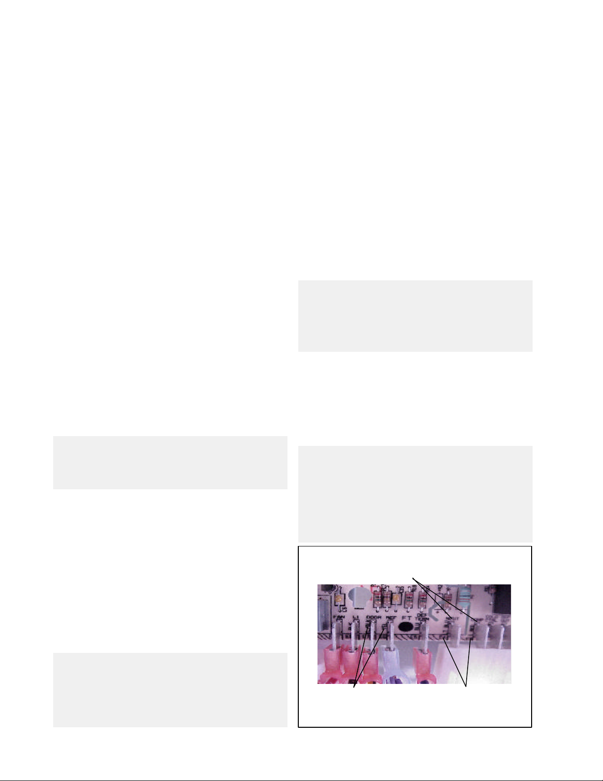
System Diagnostics
An electrical connection between the light switch and
refrigerator light bulb is coupled to the ADC system board,
providing a manual method of initiating and terminating
a defrost cycle. The refrigerator cold control MUST BE IN
THE CLOSED POSITION, calling for refrigeration, in order to initiate a defrost cycle. The procedure to manually
initiate or terminate a defrost cycle is a minimum of five
depressions of the light switch within a six second time
period. When this is done, the following will apply:
• If a defrost is initiated manually and the termination
thermostat is closed, the heater will be actuated until
the termination thermostat opens. A 6 minute drip
time follows before actuating the compressor and
setting the next defrost time.
• When terminating the defrost manually and the
termination thermostat is closed or open, the
compressor is activated and sets the next defrost
time.
An electrical connection between the defrost heater and
the defrost termination thermostat is coupled to the ADC
for system data, but also gives the technician the ability
to check electrical continuity individually of either the
defrost heater or termination thermostat from the ADC
mounting area.
The ADC printed circuit board has component identification
and lead wire color (name) adjacent to each electrical
tab. Four of the tab terminals mate with the present
defrost timer connection and the remaining 6 individual
leads will have the color name printed on the board next
to the tab matching the wire color. See Figure 24.
NOTE: Because the evaporator fan motor operates
through the ADC control, you cannot replace the
ADC with a defrost timer. (Refer to Figures 14 to 17
when doing voltage checks.
To check input power to the board (See Figure 24.):
1. Check voltage between E4 and E8. You should have
LINE VOLTAGE ± 10%.
2. If freezer control contacts are closed, there should
be LINE VOLTAGE ± 10% between E4 and E2. If no
voltage is present, check control.
3. If food compartment contacts are closed, there
should be LINE VOLTAGE ± 10% between E4 and E6.
If novoltage is present, check control.
4. With door open and refrigerator light switch contacts
closed, there should be LINE VOLTAGE ± 10% between
E4 and E7. If no voltage is present, check light switch.
To check output power from board (See Figure 24.):
1. If voltage is coming from freezer or food
compartment control, there should be LINE VOLTAGE
± 10% between E4 and E9 to operate evaporator fan
motor, unless it is in defrost or within 7 minute delay
after defrost. (See NOTE A.)If no voltage is present,
replace board.
2. If voltage is coming from freezer control, there should
be LINE VOLTAGE ± 10% at either E4 or E1, if relay is
set in defrost, or E4 to E3, if relay is set for compressor
to run.
3. If there is voltage between E4 and E3, compressor
and condenser fans should be running. If they are
not, check voltage at compressor. If voltage is
present, follow procedure to check compressor. If
voltage is not present, check wiring between ADC
and compressor.
NOTE: To change relay from compressor run to
defrost, open door and push light switch in and out 5
times within 6 seconds. The relay power should
change from E4-to-E3 to E4-to-E1. The compressor
should shut off and the defrost heater should come on.
4. If there is LINE VOLTAGE ± 10% between E4 and E1,
there should be power to defrost heater. If limit
switch is closed, heater should be on. If heater is not
operating, check voltage between E5 and E6. If heater
is not working but line voltage is present, heater is
open. If heater is not operating, and there is no voltage
between E5 and E6, limit switch is open.
NOTE A: To change relay from defrost to compressor
run, open refrigerator door and push light switch in
and out 5 times within 6 seconds. The relay power
should change from E4-to-E1 to E4-to-E3. This will
terminate the defrost cycle and start the compressor
and condenser fan running. There will be a one minute
delay in the evaporator fan starting.
Name of component connecting to
terminal is at top of terminal.
IMPORTANT NOTE: The light bulb and door switch
must be operational in order to manually initiate a
defrost cycle, or for the unit to enter vacation mode.
Manual initiation of defrost can only be done by using
the light switch in the refrigerator compartment.
Wire color is written
at side of terminal
24
Terminal number is at
bottom of terminal
Figure 24
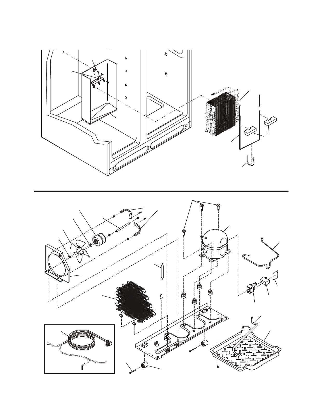
Defrost Drain Pan
Rivet
Rivot
SYSTEM EXPLODED VIEW DIAGRAM
Evaporator Bracket
Evaporator
Drain Trough
Speed Nut
Condenser Fan
Silencer
Fan
Bracket
Fan Shroud
Condenser
Brackets
Drier-Filter
Shoulder Screws
Defrost
Heater
Styrofoam
Blocks
Strap
Compressor
Suction
Tube
Clamp
Run Capacitor
PTC Starter
Drain Tube
Power Cord
Roller Pin
Rear Roller
25
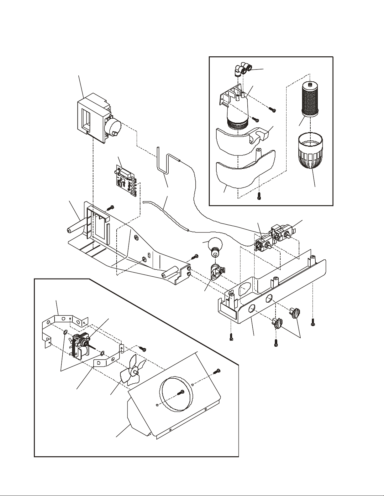
Compartment
CONTROLS EXPLODED VIEW DIAGRAM (Rear Filter)
Damper Assembly
Rear Control Box
ADC
(Adaptive Defrost Control)
Insulator
Elbow
Housing
Cover
Filter
Filter Cup
Cover
Fresh Food
Freezer Control
Control
40 Watt
Light Bulb
Rear Bracket
Bushings
Front
Bracket
Evaporator
Fan Motor
Fan Blade
Shroud, Fan Orifice
Light Socket
26
Front
Control
Box
Control
Knobs
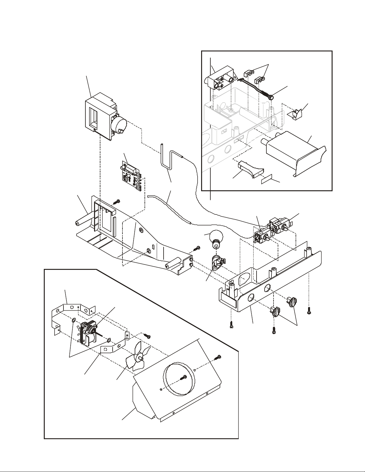
Compartment
CONTROLS EXPLODED VIEW DIAGRAM (Front Filter)
Damper Assembly
Rear Control Box
ADC
(Adaptive Defrost Control)
Insulator
40 Watt
Light Bulb
Base
Light Pipe
Cover
Freezer Control
Elbow
Housing
Retainer
Cover
Label
Filter
Release
Rod
Filter
Filter
Release
Button
Front Filter
Filter Cup
Fresh Food
Control
Rear Bracket
Bushings
Front
Bracket
Evaporator
Fan Motor
Fan Blade
Shroud, Fan Orifice
Light Socket
27
Front
Control
Box
Control
Knobs
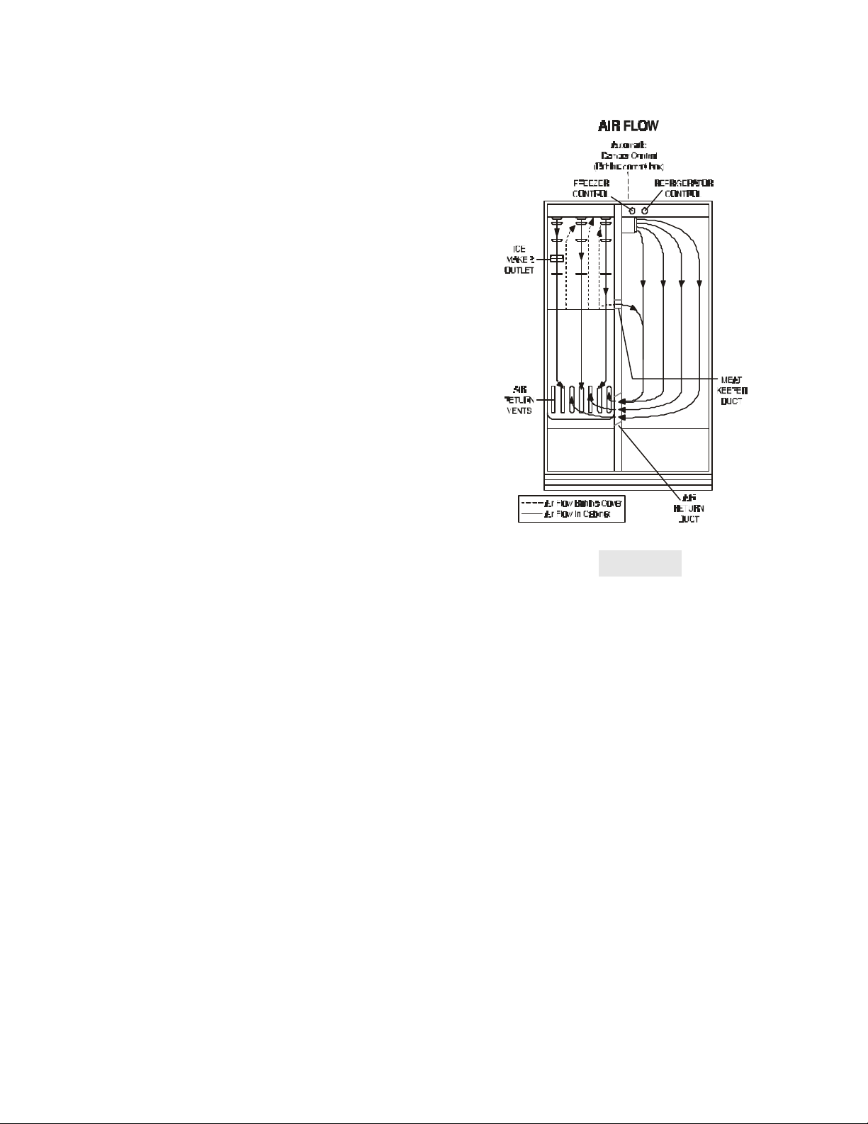
SECTION D - AIR CIRCULATION
AUTOMATIC DEFROST MODELS
Principals Of Automatic Defrost Operation
Automatic defrost refrigerators operate on the principle
that moisture or frost transfers or migrates to the coldest
surfaces (evaporator) in the freezer compartment. For
example, a small amount of water spilled in the freezer
compartment will freeze immediately. However, this ice
in time will evaporate and transfer to the colder surfaces
of the freezer evaporator coil.
Air Circulation Patterns
Automatic defrost models have a single evaporator in the
freezer compartment, and have forced air cooling in the
freezer and refrigerator compartments.
The “fin and tube” aluminum type evaporator is located
on the lower back wall of the freezer compartment. A
circulating fan (suction type) pulls air from the freezer
compartment through the grill in the bottom of the freezer
and from the refrigerator compartment through a duct
located in the separating wall in the bottom rear left hand
corner of the cabinet interior. The air is then drawn up
through the fin and tubes of the evaporator surface. The
cold air is forced into a fan cover and discharged into the
top of the freezer, and out the air discharge under the ice
maker. See Figure D1. If the food compartment control
is calling for cooling, the automatic damper control in the
top of the food compartment will open and allow cold air
to enter the food compartment. If the food compartment
calls for cooling but the fan is not running, the fan will
start as soon as the damper is open, and will continue
to run as long as the food compartment control or the
freezer control calls for cooling.
Figure D1
The air circulating fan operates any time the food
compartment control or the freezer compartment control
calls for cooling. During the defrost period, the compressor and circulating fan do not operate. The automatic
defrost timer or the ADC (Adaptive Defrost Control)
opens the electrical circuit to the fan motor and compressor.
28

SECTION E - REFRIGERATION SYSTEM
NOTICE: Instructions given here are furnished as a guide. Persons attempting to use these instructions to make
repairs to the sealed refrigeration system should have a working knowledge of refrigeration and previous training
on sealed system repair, and an EPA certification for servicing refrigeration systems.
IMPORTANT NOTICE
Effective July 1, 1992, the United States clean air act governs the disposal of refrigerants such
as R-134a. Therefore, when discharging or purging the sealed system use an epa approved
refrigerant recovery system as outlined in the final rule on the protection of stratospheric
ozone and refrigerant recycling, which was published in the Federal Register May 14, 1993.
NOTE: Electrolux does not permit the use of recovered refrigerant in the servicing of our products for in-
warranty and out-of-warranty repairs. Therefore, only new refrigerant or refrigerant that has been reclaimed
back to new specifications by a refrigerant manufacturer is to be used.
DEFINITIONS
Recovery:
To remove refrigerant in any condition from a system
and store it in an external container without necessarily
testing or processing it in any way.
Recycling:
To clean refrigerant for reuse by oil separation and
single or multiple passes through devices, such as
replaceable core filter-driers, which reduce moisture,
acidity and particulate matter. This term usually applies
to procedures implemented at the field job site or at a
local service shop.
Reclaim:
To reprocess refrigerant to new product specifications
by means which may include distillation. Will require
chemical analysis of the refrigerant to determine that
appropriate product specifications are met. This term
usually implies the use of processes or procedures
available only at a reprocessing or manufacturing facility.
SAFETY WARNINGS
Compressor Testing
Whenever testing a compressor, extreme caution should
be used to prevent damaging the terminals. A
compressor with a damaged terminal or a grounded
winding can expel a terminal from its insulated housing
when the compressor is energized. If this happens, a
mixture of refrigerant and oil will be released that could
be ignited by an external heat source (open flame,
heater, etc.). Also, if there is air in the system when this
happens, a spark at the compressor shell could ignite
the refrigerant and oil mixture.
Charging Sealed Systems
Overcharging a refrigeration system with refrigerant can
be dangerous. If the overcharge is sufficient to immerse
the major parts of the motor and compressor in liquid
refrigerant, a situation has been created which, when
followed by a sequence of circumstances can lead to the
compressor shell seam separating.
A hydraulic block occurs, preventing the compressor
from starting. This condition is known as locked rotor.
Electric current continues to flow through the
compressor motor windings which become, in effect,
electric resistance heaters. The heat produced begins to
vaporize the excess refrigerant liquid causing a rapid
increase in system pressure. If the compressor
protective devices fail, the pressure within the system
may rise to extremes far in excess of the design limits.
Under these conditions, the weld seam around the
compressor shell can separate with explosive force,
spewing oil and refrigerant vapor which could ignite.
To eliminate this exceedingly rare but potential hazard,
never add refrigerant to a sealed system. If refrigerant is
required, evacuate the existing charge and recharge
with the correct measured amount of the refrigerant
specified for the system.
29
 Loading...