

Pro-Installation Requirements ................................................................. 2
Electrical Requirements ........................................................................... 2
I
I
stallati
==
struct=
Instrucciones
para
Instalaci6n
Before beginning installation, carefully read these instructions. This will simpfify the installation and ensure the dryer is installed correctly
and safely. Leave these instructions near the Dryer after installation for future reference.
NOTE: The electrical service to the Dryer must conform with local codes and ordinances and the latest edition of the National Electrical Code, ANSI/NFPA
70, or in Canada, the Canadian electrical code C22.1 part 1.
NOTE: The gas service to the Dryer must conform with local codes and ordinances and the latest edition of the National Fuel Gas Code ANSi Z223.1, or
in Canada, CAN/ACG B149.1-2000
NOTE: The Dryer is designed under ANSi Z 21.5.1 or ANSI/UL 2158 - CAN/CSA C22.2 No. 112 (latest editions) for HOME USE only. This Dryer is not
recommended for commercial applications suct_ as restaurants or beauty salons, etc.
Exhaust System Requirements .................................................... 2-3
GasSupply Requirements ........................................................................ 3
Location of Your Dryer............................................................................. 3
Rough-in Dimensions ............................................................................... 4
Mobile Home installation ......................................................................... 5
Unpacking .......................................................................................... 5
Reversing Door Swing ............................................................................. 6
Electrical installation ........................................................................ 7
Grounding Requirements ................................................................ 7
Electrical Connections--3-wire ............................................................... 7
Electrical Connections--4-wire .............................................................. 8
GasConnection ...................................................................................... 8
General installation ................................................................................. 8
Replacement Parts.................................................................................. 8
EspanOI .................................................................. 9-1 5
Requerimientos de instalaci0n preliminares ............................................. .9
Requerimientos electricos ........................................................................ 9
Requerimientos del sistema de escape ............................................. 9-10
Requerimientos del suministro degas..................................................... 10
Ubicad6n desu secadora ....................................................................... 10
Dimensiones para la instalad0n .......................................................... 11
InstaBci6n en casas moviles ............................................................. 12
Desembalaje .............................................................................. 12
Puerta reversible ........................................................................ 13
Instalacion electrica ....................................................................... 14
Requerimientos para la puesta a tierra .......................................... 14
Conexi6nes electricas - trifilares ................................................ 14
Conexi6nes ebctricas - tetrafilares ............................................... 15
Conexi0n del gas ........................................................................... 15
General Instalaci6n ............................................................................ 15
Piezas de recambio ....................................................................... 15
Antes de comenzar la instalacion, lea cuidadosamente estas instrucciones. Esto simplificar_ la instalacion y asegurar_ que la secadora se
instale correctamente y de manera segura. Despu_s de comp/etar /a instalacion, co/oque estas instrucciones cerca de /a secadora para
referencia futura.
NOTA: La alimentaci6n electrica para la secadora debera cumpNr con los cOdigos y reglamentos locales y con la Oltima ediciOn del C6digo Electrico National,
ANSI/NFPA 70.
NOTA: La alimentaci6n de gas para la secadora debera cumplir con los codigos y reglamentos locales y con la 01tima edition del C6digo National para Gases
Combustibles, ANSi Z223.1.
NOTA: La secadora esta dasificada para USO DOMESTiCO solamente, de acuerdo con la norma ANSi Z 21.5.1 o ANSI/UL 2158 - CAN/CSA C22.2 (las 01timas
ediciones). Esta secadora no se recomienda para uso commercial tal como en restaurantes, salones de belleza, etc.
I__ For your safety the information in this manual must be followed to minimize the risk of fire or explosion or to prevent property damage,
personal injury or loss of life.
- Do not store or use gasoline or other flammable vapors and liquid in the vicinity of this or any other appliance.
- WHAT TO DO IF YOU SMELL GAS
• Do not try to light any appliance.
• Do not touch any electrical switch; do not use any phone in your building.
Clear the room, building or area of all occupants.
Immediately call your gas supplier from a neighbor's phone. Follow the gas supplier's instructions.
If you cannot reach your gas supplier, call the fire department.
Installation and service must be performed by a qualified installer, service agency or the gas supplier.
F_ Para su seguridad, siga las instrucciones contenidas en este manual a fin de reducir a un minimo los riesgos de incendio o explosion o
para evitar da_os materiabs, lesiones personabs o la muerte.
No almacene ni utiNce gasolina u otros vapores y Nquidos inflamabbs en la proximidad de este o de cualquier otto artefacto electrico.
QUE DEBE HACER SI PERCIBE OLOR A GAS
• No trate de encender ning0n artefacto electrico.
• No toque ning0n interruptor electrico; no use ning0n telefono en su edificio.
• Haga salir atodos los ocupantes de la habitation, del edificio y del lugar.
• Llame a su proveedor de gas desde el telefono de un vecino. Siga las instrucciones del proveedor de gas.
• Si no Iogra comunicarse con su proveedor de gas, Ilame al departamento de bomberos.
La instalaciOn y el servicio de mantenimiento debe de realizados un instalador calificado, la agencia de servicios o el proveedor de gas.
Printed in U.S.A. P/N134734400A (0606)
PRE-INSTALLATION REQUIREMENTS
Tools and Materials Required for Installation:
1. Phillips head screwdriver.
2. Channel-lock adjustable pliers.
3. Carpenter's level.
4. Flat or straight blade screwdriver.
5. Duct tape.
6. Rigid or flexible metal 4 inch (10.2 cm) duct.
7. Vent hood.
8. Pipe thread sealer (Gas).
9. Plastic knife.
ELECTRICAL REQUIREMENTS
[ ELECTR/C Dryer ]
CIRCUIT - Individual 30 amp. branch circuit fused with 30 amp. time delay
fuses or circuit breaker.
Use separately fused circuits for washers and dryers, and DO NOT operate
a washer and a dryer on the same circuit.
POWER SUPPLY - 3 wire or 4-wire, 240 volt, single phase, 60 Hz,Alternating
Current.
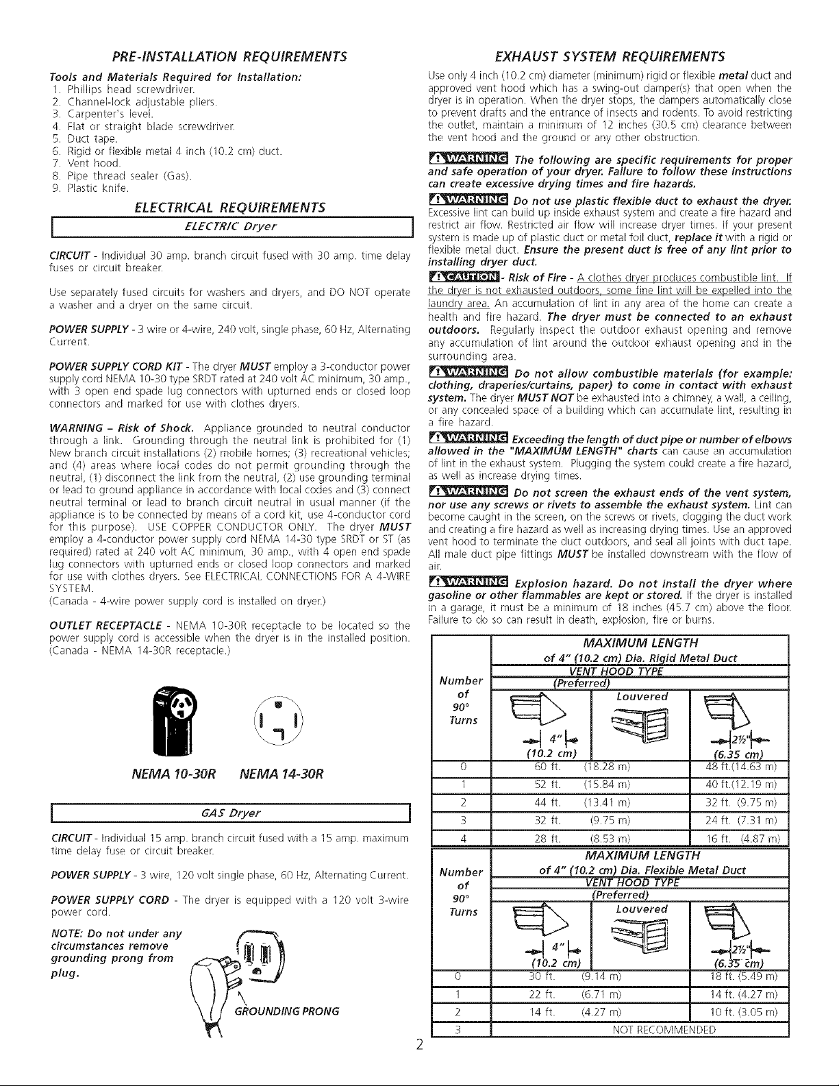
POWER SUPPLY CORD KIT - The dryer MUST employ a 3-conductor power
supply cord NEMA 10-30 type SRDTrated at 240 volt AC minimum, 30 amp.,
with 3 open end spade lug connectors with upturned ends or closed loop
connectors and marked for use with clothes dryers.
WARNING - Risk of Shock. Appliance grounded to neutral conductor
through a link. Grounding through the neutral link is prohibited for (I)
New branch circuit installations (2) mobile homes; (3) recreational vehicles;
and (4) areas where local codes do not permit grounding through the
neutral, (1) disconnect the link from the neutral, (2) use grounding terminal
or lead to ground appliance in accordance with local codes and (3) connect
neutral terminal or lead to branch circuit neutral in usual manner (if the
appliance is to be connected by means of a cord kit, use 4-conductor cord
for this purpose). USE COPPER CONDUCTOR ONLY. The dryer MUST
employ a 4-conductor power supply cord NEMA 14-30 type SRDT or ST (as
required) rated at 240 volt AC minimum, 30 amp., with 4 open end spade
lug connectors with upturned ends or closed loop connectors and marked
for use with clothes dryers. See ELECTRICALCONNECTIONS FOR A 4-WIRE
SYSTEM.
(Canada - 4-wire power supply cord is installed on dryer.)
OUTLET RECEPTACLE - NEMA 10-30R receptacle to be located so the
power supply cord is accessible when the dryer is in the installed position.
(Canada - NEMA 14-30R receptacle.)
EXHAUST SYSTEM REQUIREMENTS
Use only 4 inch (10.2 cm) diameter (minimum) rigid or flexible metal duct and
approved vent hood which has a swing-out damper(s) that open when the
dryer is in operation. When the dryer stops, the dampers automatically close
to prevent drafts and the entrance of insects and rodents. To avoid restricting
the outlet, maintain a minimum of 12 inches (30.5 cm) clearance between
the vent hood and the ground or any other obstruction.
and safe operation of your dryer. Failure to follow these instructions
can create excessive drying times and fire hazards.
Excessive lint can build up inside exhaust system and create a fire hazard and
restrict air flow. Restricted air flow will increase dryer times. If your present
system is made up of plastic duct or metal foil duct, replace it with a rigid or
flexible metal duct Ensure the present duct is free of any lint prior to
installing dryer duct.
rf_m - Risk of Fire - A clothes dryer produces combustible lint. If
the dryer is not exhausted outdoors some fine lint will be expelled into the
laundry area. An accumulation of lint in any area of the home can create a
health and fire hazard. The dryer must be connected to an exhaust
outdoors. Regularly inspect the outdoor exhaust opening and remove
any accumulation of lint around the outdoor exhaust opening and in the
surrounding area.
clothing, draperies/curtains, paper) to come in contact with exhaust
system. The dryer MUSTNOT be exhausted into a chimney, a wall, a ceiling,
or any concealed space of a building which can accumulate lint, resulting in
a fire hazard.
allowed in the "MAXIMUM LENGTH" charts carl cause an accumulation
of Nnt in the exhaust system. Plugging the system could create a fire hazard,
as well as increase drying times.
nor use any screws or rivets to assemble the exhaust system. Lint can
become caught in the screen, on the screws or rivets, clogging the duct work
and creating a fire hazard as well as increasing drying times. Use an approved
vent hood to terminate the duct outdoors, and seal all joints with duct tape.
All male duct pipe fittings MUST be installed downstream with the flow of
air.
gasoline or other flammables are kept or stored. If the dryer is installed
in a garage, it must be a minimum of 18 inches (45.7 cm) above the floor.
Failure to do so can result in death, explosion, fire or burns.
Number (Preferred)
The following are specific requirements for proper
Do not use plastic flexible duct to exhaust the dryer.
Do not allow combustible materials (for example:
Exceeding the length of duct pipe or number of elbows
Do not screen the exhaust ends of the vent system,
Explosion hazard. Do not install the dryer where
MAXIMUM LENGTH
of 4" (10.2 cm) Dia. Rigid Metal Duct
VENT HOOD TYPE
NEMA 10-30R NEMA 14-30R
i GAS Dryer i
CIRCUIT- Individual 15 amp. branch circuit fused with a 15 amp. maximum
time delay fuse or circuit breaker.
POWER SUPPLY- 3 wire, 120 volt single phase, 60 Hz, Alternating Current.
POWER SUPPLY CORD - The dryer is equipped with a 120 volt 3-wire
power cord.
NOTE: Do not under any
circumstances remove
grounding prong from
plug,
_GXROUNDINGPRONG
of Louvered %
.q
(10.2 cm) (6.35 cm)
0 60 ft. (18.28 m) 48 ft.(14.6S m)
1 52 ft. (15.84 m) 40 ft.(12.19 m)
2 44 ft. (13.41 m) 32 ft. (9.75 m)
3 32 ft. (9.75 m) 24 ft. (7.31 m)
4 28 ft. (8.53 m) 16 ft. (4.87 m)
MAXIMUM LENGTH
Number of 4" (10.2 cm) Dia. Flexible Metal Duct
of VENT HOOD TYPE
90° (Preferred)
0 30 ft. (9.14 m) 18 ft. (5.49 m)
1 22 ft. (6.71 m) 14 ft. (4.27 m)
2 14 ft. (4.27 m) 10 ft. (3.05 m)
3 NOT RECOMMENDED
NCORRECT
7. The dryer MUST be isolated from the gas supply piping system during
any pressure testing of the gas supply piping system at test pressures
equal to or less than
1/2 psig (:3.45 kPa).
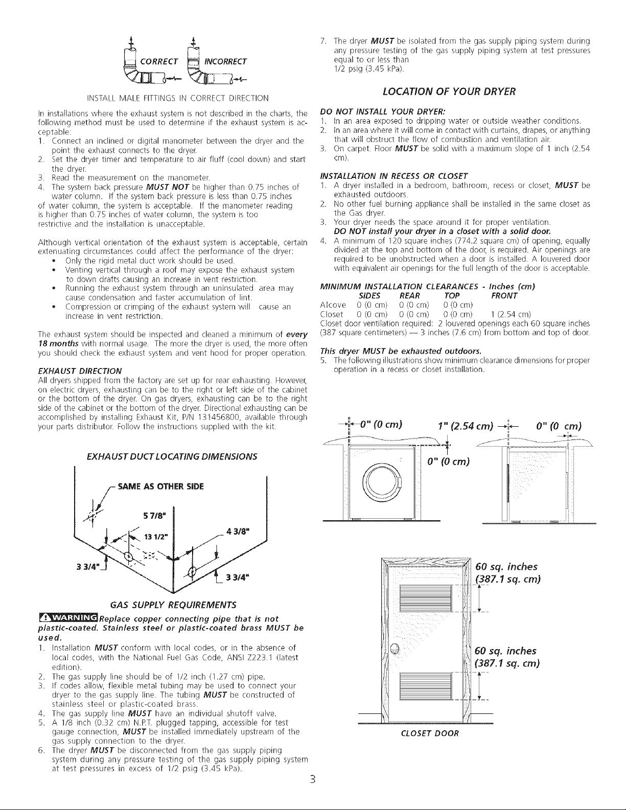
INSTALL MALE FITTINGS IN CORRECT DIRECTION
In installations where the exhaust system is not described in the charts, the
following method must be used to determine if the exhaust system is ac-
ceptable:
1. Connect an inclined or digital manometer between the dryer and the
point the exhaust connects to the dryer.
2. Set the dryer timer and temperature to air fluff (cool down) and start
the dryer.
3. Read the measurement on the manometer.
4. The system back pressure MUST NOT be higher than 0.75 inches of
water column. If the system back pressure is less than 0.75 inches
of water column, the system is acceptable. If the manometer reading
is higher than 0.75 inches of water column, the system is too
restrictive and the installation is unacceptable.
Although vertical orientation of the exhaust system is acceptable, certain
extenuating circumstances could affect the performance of the dryer:
o Only the rigid metal duct work should be used.
Venting vertical through a roof may expose the exhaust system
to down drafts causing an increase in vent restriction.
Running the exhaust system through an uninsulated area may
cause condensation and faster accumulation of lint.
Compression or crimping of the exhaust system will cause an
increase in vent restriction.
The exhaust system should be inspected and cleaned a minimum of every
18 months with normal usage. The more the dryer is used, the more often
you should check the exhaust system and vent hood for proper operation.
EXHAUST DIRECTION
All dryers shipped from the factory are set up for rear exhausting. Howevei;
on electric dryers, exhausting can be to the right or left side of the cabinet
or the bottom of the dryer. On gas dryers, exhausting can be to the right
side of the cabinet or the bottom of the dryer. Directional exhausting can be
accomplished by installing Exhaust Kit, P/N 131456800, available through
your parts distributor. Follow the instructions supplied with the kit.
LOCATION OF YOUR DRYER
DO NOT INSTALL YOUR DRYER:
1. In an area exposed to dripping water or outside weather conditions.
2. In an area where itwill come in contact with curtains, drapes, or anything
that will obstruct the flow of combustion and ventilation air.
3. On carpet. Floor MUST be solid with a maximum slope of 1 inch (2.54
cm).
INSTALLATION IN RECESS OR CLOSET
1. A dryer installed in a bedroom, bathroom, recess or closet, MUST be
exhausted outdoors.
2. No other fuel burning appliance shall be installed in the same closet as
the Gas dryer.
3. Your dryer needs the space around it for proper ventilation.
DO NOT install your dryer in a closet with a solid door.
4. A minimum of 120 square inches (774.2 square cm) of opening, equally
divided at the top and bottom of the door, is required. Air openings are
required to be unobstructed when a door is installed. A Iouvered door
with equivalent air openings for the full length of the door is acceptable.
MINIMUM INSTALLATION CLEARANCES - Inches (cm)
Alcove 0 (0 cm) 0 (0 cm) 0 (0 cm)
Closet 0 (0 cm) 0 (0 cm) 0 (0 cm) 1 (2.54 cm)
Closet door ventilation required: 2 Iouvered openings each 60 square inches
(387 square centimeters) -- 3 inches (7.6 cm) from bottom and top of door.
This dryer MUST be exhausted outdoors.
5. The following illustrations show minimum clearance dimensions for proper
SIDES REAR TOP FRONT
operation in a recess or closet installation.
ii u
_,i'_O" (0 cm) 1" (2.54 cm) _-ll'_ O" (0 cm)
EXHAUST DUCT LOCATING DIMENSIONS
SAME AS OTHER SIDE
GAS SUPPLY REQUIREMENTS
_Replace copper connecting pipe that is not
plastic-coated. Stainless steel or plastic-coated brass MUST be
used.
1. Installation MUST conform with local codes, or in the absence of
local codes, with the National Fuel Gas Code, ANSI Z223.1 (latest
edition).
2. The gas supply line should be of 1/2 inch (1.27 cm) pipe.
3. If codes allow, flexible metal tubing may be used to connect your
dryer to the gas supply line. The tubing MUST be constructed of
stainless steel or plastic-coated brass.
4. The gas supply line MUST have an individual shutoff valve.
5. A 1/8 inch (0.32 cm) N.RT. plugged tapping, accessible for test
gauge connection, MUST be installed immediately upstream of the
gas supply connection to the dryer.
6. The dryer MUST be disconnected from the gas supply piping
system during any pressure testing of the gas supply piping system
at test pressures in excess of 1/2 psig (:3.45 kPa).
cm)
i!i
CLOSET DOOR
3
23%"
(60.33)
inches (cm)
25/8"
(6.67)
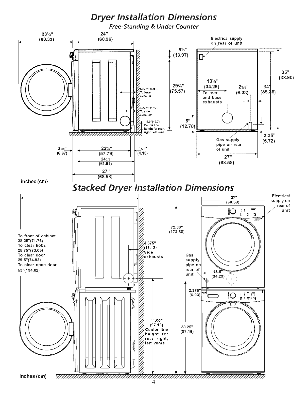
Dryer Installation Dimensions
Free-Standing & Under Counter
Electrical supply
on rear of unit
J
/
29%"
5,875"(_4.93) 75.57)
To base
exhaust
4,375"(_ 1._2)
To side _,exhausts
5.0"(12.7) 5 _
Centerline (1 2.70)
, height for rear, --
i right, left vent _'
223/. ''
(57.79)
24318"
(61,91)
27"
/
(68.58)
Stacked Dryer instaflation Dimensions
13½"
(34.29) 23/8"
To rear = (6.03)
and base
exhausts --_
Gas su_pply l 2.25"
pipe on rear
of unit
(68.58)
2T _
27"
(68.s8)
io
35"
(88.90)
34'
(86.:6)
J
(5.72)
Electrica!
supply on
rear of
_ unit
To front of cabinet
28.25"(71.76)
To clear kobs
28.75"(73.03)
To clear door
29.5"(74.93)
To clear open door
53"(134.62)
(
\
!
I
_.375"
[1!.12)
;Side
exhausts
41.00"
(97.16)
Center line
i height for
i rear, right,
;left vents
72.00"
(172.88)
Gas
supply
pipe on
rear of
unit
38.25"
(97.16)
2.375"J
(6.03)
(34.29) _ ,
l--I
inches (cm)
4

MOBILE HOME INSTALLATION
UNPACKING
1. Dryer MUST be exhausted outside (outdoors, not beneath the
mobile home) using metal ducting that will not support
combustion. Metal ducting must be 4 inches (10.16 cm) in
diameter with no obstructions. Rigid metal duct is preferred.
2. If dryer is exhausted through the floor and area beneath the
mobile home is enclosed, the exhaust system MUST terminate
outside the enclosure with the termination securely fastened
to the mobile home structure.
3. When installing a gas dryer into a mobile home, a provision
must be made for outside make up air. This provision is to be
not less than twice the area of the dryer exhaust outlet.
4. This dryer MUST be fastened to the floor. Mobile Home
Installation Kit No. 346764 is available from your dealer.
5. Refer to pages 2 and 3 for other important venting
requirements.
6. Installation MUST conform to current Manufactured Home
Construction & Safety Standard (which is a Federal Regulation
Title 24 CFR-Part 32-80) or when such standard is not applicable,
with American National Standard for Mobile Homes.
The dryer is designed under ANSI Z 21.5.1 or
ANSI/UL2158 - CAN/CSA C22.2 (latest editions) for HOME USE
only.
1. Using a rug, blanket or a piece of cardboard packing to protect
the floor, carefully lay the dryer on its left side and remove the
foam shipping base.
2. Return the dryer to an upright position.
FOAM
SHIPPING
_P_C KING
ii
: ¸¸¸DO
Correct
DON'T
Incorrect
 Loading...