

Page 1
Identification:
Technical Bulletin no:
Date:
Issuer:
Factory:
Subject
Model
Problem
Reason
Action in Factory
ELECTROLUX PROFESSIONAL SPA
MAILING ADDRESS TELEPHONE WEBSITE VAT NO.
VIALE TREVISO, 15
33170 PORDENONE - ITALY
OFFICE ADDRESS TELEFAX E-MAIL ADDRESS
VIALE TREVISO, 15
33170 PORDENONE - ITALY
C08
PDD2005-08 (page 1 of 10), 2nd
23 May 2005
Filippo Fingolo (Ovens Customer Support
Dept.)
PDD Vallenoncello - Italy
New regulations for AOS gas ovens
All AOS gas combi lenghtwise ovens
Possibility of whistling noise during oven working
Differences in LPG mixture
From SN 513 introduced new gas regulations (see table) and
components, also alternative solutions (LPG1 and LPG2) for LPG
installations:
for 6 gas combi ovens:
- new cavity burner (0C1082), replaced pieces In sparepart wharehouse
for 10 1/1 and 20 1/1 gas combi ovens:
- new PWM parameters
- offset regulations with range of values
- new nozzle with diameter 5,50 for cavity burner (spare part code
0C2442) for LPG2/G30 installations
for 10 2/1 gas combi ovens:
- new PWM parameters
- offset regulations with range of values
for 20 2/1 gas combi ovens:
- new PWM parameters
- offset regulations with range of values
- new nozzles with diameter 7,50 (0C2444), 6,00 (0C2445), 5,80
(0C2446) for boiler burners
- new aerator (red one, 0C1045) for boiler burners
- new chimneys for boiler (0C2447)
- new burner for the boiler (0C2190), spare part updated with the new
burner
- introduction of a circular mesh (0C2513) and a circular restriction
(0C2514) on boiler’s
++39 0434 380528 www.electrolux.com 00072220932
++39 0434 380555 filippo.fingolo@electrolux.it
Page 2
Action in Field
- Nozzles, chimneys, aerators, burner, meshes and restrictions available
also in the kit 0C2515
See below the new calibrations and instructions for gas conversion
2
Page 3
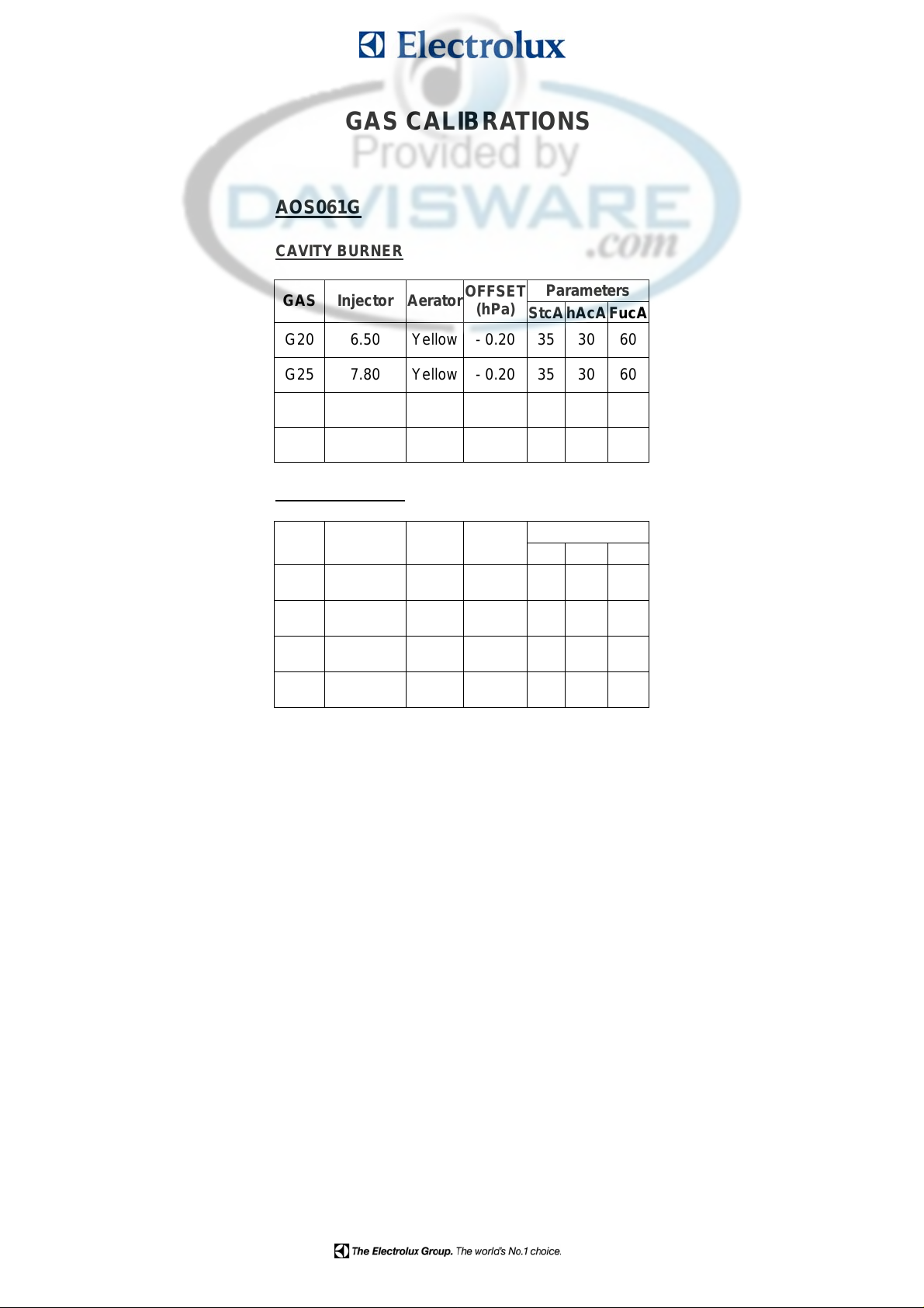
GAS CALIBRATIONS
AOS061G
CAVITY BURNER
GAS Injector Aerator
G20 6.50 Yellow - 0.20 35 30 60
G25 7.80 Yellow - 0.20 35 30 60
G30 5.30 Yellow - 0.25 40 28 43
LPG 5.30 Yellow - 0.13 40 28 43
BOILER BURNER
GAS Injector Aerator
OFFSET
(hPa)
Parameters
StcAhAcAFucA
OFFSET
(hPa)
Parameters
Stbo hAbo Fubo
G20 6.50 Yellow - 0.20 55 35 78
G25 7.80 Yellow - 0.20 55 35 78
G30 5.30 Yellow - 0.28 55 36 66
LPG 5.30 Yellow - 0.18 55 36 66
3
Page 4

AOS101G
CAVITY BURNER
GAS InjectorAerator
OFFSET
(hPa)
Parameters
StcAhAcAFucA
G20 7.00 Red - 0.25 80 26 100
G25 8.00 Red - 0.25 80 26 100
LPG2/G30 5.50 Red - 0.07 ÷ 0.00 23 26 100
LPG1 5.70 Red - 0.15 ÷ - 0.08 23 26 100
BOILER BURNER
GAS InjectorAerator
OFFSET
(hPa)
Parameters
Stbo hAbo Fubo
G20 7.00 Red - 0.10 50 50 100
G25 8.00 Red - 0.10 40 50 100
G30 5.70 Red - 0.28 33 45 74
LPG 5.70 Red - 0.15 33 45 74
LPG conversion for cavity burner for AOS101G
For LPG installations, put the ø 21 flow reducer flange between cavity burner fan and cavity burner. Change the
PWM parameters.
Then change the injector with the 5.70 one and calibrate the offset in the range - 0.15 ÷ - 0.08 hPa so as to
eliminate possible whistles/noises (row LPG1). After you have found the best working condition, cool down and
verify ignitions with cold burner.
If the previous setting does not eliminate whistles or noise, change the 5.70 injector with the 5.50 one and use the
calibrations of LPG2/G30 row: calibrate the offset in the range - 0.07 ÷ 0.00 hPa so as to eliminate possible
whistles/noises (row LPG1). After you have found the best working condition, cool down and verify ignitions with
cold burner.
4
Page 5

AOS201G
UPPER CAVITY BURNER
GAS Injector Aerator
G20 7.00 Red - 0.25 80 26 100
G25 8.00 Red - 0.25 80 26 100
LPG2/G30 5.50 Red - 0.07 ÷ 0.00 23 26 100
LPG1 5.70 Red - 0.15 ÷ - 0.08 23 26 100
LOWER CAVITY BURNER
GAS Injector Aerator
G20 7.00 Red - 0.25 80 26 100
OFFSET
(hPa)
Parameters
StcA hAcA FucA
OFFSET
(hPa)
Parameters
StcA hAcA FucA
G25 8.00 Red - 0.25 80 26 100
LPG2/G30 5.50 Red - 0.07 ÷ 0.00 23 26 100
LPG1 5.70 Red - 0.15 ÷ - 0.08 23 26 100
BOILER BURNER
GAS Injector Aerator
OFFSET
(hPa)
Parameters
Stbo hAbo Fubo
G20 8.00 Blue 0 42 45 100
G25 8.50 Blue 0 42 45 100
G30 6.15 Blue - 0.15 30 37 72
LPG 6.15 Blue 0 30 37 72
LPG conversion for cavity burner for AOS201G
For LPG installations, put the ø 21 flow reducer flange between cavity burner fan and cavity burner. Change the
PWM parameters.
Then change the injector with the 5.70 one and calibrate the offset in the range - 0.15 ÷ - 0.08 hPa so as to
eliminate possible whistles/noises (row LPG1). After you have found the best working condition, cool down and
verify ignitions with cold burner.
If the previous setting does not eliminate whistles or noise, change the 5.70 injector with the 5.50 one and use the
calibrations of LPG2/G30 row: calibrate the offset in the range - 0.07 ÷ 0.00 hPa so as to eliminate possible
whistles/noises (row LPG1). After you have found the best working condition, cool down and verify ignitions with
cold burner.
5
Page 6

AOS102G
CAVITY BURNER
OFFSET (hPa) Parameters
GAS Injector Aerator
StcA
hAcA FucA
G20 7.00 Red - 0.17 ÷ - 0.10 45 43 100
G25 8.50 Red - 0.17 ÷ - 0.10 45 43 100
G30 5.70 Red - 0.25 ÷ - 0.18 60 43 100
LPG 5.70 Red - 0.10 ÷ - 0.02 60 43 100
BOILER BURNER
GAS Injector Aerator
OFFSET (hPa) Parameters
Stbo hAbo Fubo
G20 7.00 Red 0 43 50 100
G25 8.50 Red 0 43 50 100
G30 5.70 Red - 0.15 35 45 78
LPG 5.70 Red 0 35 45 78
LPG conversion for cavity burner for AOS102G
For LPG installations, put the ø 25 flow reducer flange between cavity burner fan and cavity burner. Change the
PWM parameters.
Then change the injector with the 5.70 one and calibrate the offset in the range - 0.10 ÷ - 0.02 hPa so as to
eliminate possible whistles/noise. After you have found the best working condition, cool down and verify ignitions
with cold burner.
6
Page 7

AOS202G
UPPER CAVITY BURNER
GAS Injector AeratorOFFSET (hPa)
G20 7.00 Red - 0.20 45 43 100
G25 8.00 Red - 0.20 45 43 100
G30 5.70 Red - 0.20 ÷ - 0.15 40 43 95
LPG 5.70 Red - 0.10 ÷ - 0.05 40 43 95
LOWER CAVITY BURNER
GAS Injector AeratorOFFSET (hPa)
G20 7.00 Red - 0.20 45 43 100
Parameters
StcA hAcA FucA
Parameters
StcA hAcA FucA
G25 8.00 Red - 0.20 45 43 100
G30 5.70 Red - 0.25 ÷ - 0.20 40 43 95
LPG 5.70 Red - 0.15 ÷ - 0.10 40 43 95
UPPER BOILER BURNER
GAS Injector AeratorOFFSET (hPa)
Parameters
Stbo hAbo Fubo
G20 7.50 Red - 0.05 ÷ 0.00 40 50 100
G25 8.50 Red - 0.05 ÷ 0.00 40 50 100
LPG2/G30 5.80 Red - 0.07 ÷ - 0.02 40 45 90
LPG1 6.00 Red - 0.07 ÷ - 0.02 40 45 90
LOWER BOILER BURNER
GAS Injector AeratorOFFSET (hPa)
Parameters
Stbo hAbo Fubo
G20 7.50 Red - 0.05 ÷ 0.00 40 50 100
G25 8.50 Red - 0.05 ÷ 0.00 40 50 100
LPG2/G30 5.80 Red - 0.07 ÷ - 0.02 40 45 90
LPG1 6.00 Red - 0.07 ÷ - 0.02 40 45 90
7
Page 8

LPG conversion for cavity burners for AOS202G
For LPG installations, put the ø 25 flow reducer flange between cavity burner fan and cavity burner. Change the
PWM parameters.
Then change the injector with the 5.70 one and calibrate the offset in the range - 0.10 ÷ - 0.05 hPa (upper cavity
boiler) and - 0.15 ÷ - 0.10 hPa (lower cavity boiler) so as to eliminate possible whistles/noise. After you have found
the best working condition, cool down and verify ignitions with cold burner.
LPG conversion for boiler burners for AOS202G
Change the PWM parameter.
Then change the injector with the 6.00 one and calibrate the offset in the range - 0.07 ÷ - 0.02 hPa (upper and
lower boiler burner) so as to eliminate possible whistles/noise (row LPG1). After you have found the best working
condition, cool down and verify ignitions with cold burner.
If the previous setting does not eliminate whistles or noise, change the 6.00 injector with the 5.80 one and use the
calibration of LPG2/G30 row: calibrate the offset in the range - 0.07 ÷ - 0.02 hPa (upper and lower boiler burner) so
as to eliminate possible whistles/noise. After you have found the best working condition, cool down and verify
ignitions with cold burner.
ONLY FOR AOS202 GAS INSTALLATIONS – from serial number 513
Specified with a label on the roof of 202 gas ovens exact position for boiler’s chimneys, also with a label
on chimney.
For AOS202 gas ovens introduced a new chimney with 3 holes to reduce whistle.
0C2447
8
Page 9

Created a RETROFIT KIT BOILER ASSEMBLY 0C2515 for AOS 202 gas to eliminate noises on ovens
produced before sn 513:
0C2515
The kit includes the following pieces:
- circular mesh 0C2513 2 pieces
- circular restriction 0C2514 2 pieces
- nozzles 7,50 mm 0C2444 2 pieces
- nozzles 8,50 mm 0C1143 2 pieces
- nozzles 5,80 mm 0C2446 2 pieces
- nozzles 6,0 mm 0C2445 2 pieces
- boiler burner 0C2190 1 piece
- boiler chimney ( 3 holes) 0C2447 2 pieces
- red aerator 0C1045 2 pieces
9
Page 10

To use circular restrictions and meshes here you can find explanation:
CIRCULAR RESTRICTION 0C2514
You have to insert on the top of the boiler the mesh (just put it into) and fix the restriction with 3 or 4
welding points or, alternatively, you can fix them by deforming with a hammer and a chisel the edge
of pipe once you have fixed them.
Also on boiler’s fans changed green aerators with red ones:
0C1045
10
 Loading...