

Page 1

MIXED FUEL RANGE COOKER
RM 850CN
RM 850GRN
Page 2

2
Page 3
CONTENTS
Instructions for the user Instructions for the installer
Important Safety Information
Description of the appliance
Use of appliance
- Using the electric oven
- Using the electric grill
- Rotisserie
- Hints & Tips
- Using the Hob
Maintenance and Cleaning
- Oven bulb replacement
Something Not Working
Service & Spare Parts
Customer Care
Guarantee Conditions
4
Safety Advice
5
Technical Features
6
Location
6
7
9
9
10
13
14
15
16
16
17
- Ventilation
- Levelling
Electrical connection
Gas connections
Conversion of gas
18
19
20
20
21
22
23
25
How to read the instruction book
The symbols below will guide you when reading the
instruction book
Safety instructions
Step by Step Operation
Advice and recommendations
Environmental Information
3
Page 4
IMPORTANT SAFETY INFORMATION
You MUST read these warnings carefully before installing or using the appliance. If you
need assistance, contact our Customer Care Department on 08705 950950.
Installation
• This cooker must be installed by qualified
personnel, according to the manufacturer’s
instructions and to the relevant British
Standards.
• This cooker is heavy. Take care when
moving it.
• Any gas installation must be carried out by a
registered CORGI installer.
• Any electrical installation must be carried out
by a qualified electrician/competent person.
• Remove all packaging before using the
cooker.
• Ensure that the gas and electrical supply
complies with the type stated on the rating
plate, located near the gas supply pipe.
• Do not attempt to modify the cooker in any
way.
Child Safety
• This cooker is designed to be operated by
adults. Do not allow children to play near or
with the cooker.
• The cooker gets hot when it is in use.
Children should be kept away until it has
cooled.
• Children can also injure themselves by
pulling pans or pots off the cooker.
During Use
• This cooker is intended for domestic cooking
only. It is not designed for commercial or
industrial purposes.
• When in use a gas cooker will produce heat
and moisture in the room in which it has
been installed. Ensure there is a continuous
air supply, by keeping air vents in good
condition or installing a cooker hood with a
venting hose.
• When using the cooker for a long period
time, the ventilation should be improved, by
opening a window or increasing the
extractor speed.
• Do not use this cooker if it is in contact with
water. Do not operate the cooker with wet
hands.
• Ensure the control knobs are in the ‘OFF’
position when not in use.
• When using other electrical appliances,
ensure the cable does not come into contact
with the hot surfaces of the cooker.
• Unstable or misshapen pans should not be
used on the hob burners as unstable pans
can cause an accident by tipping or spillage.
• Never leave the cooker unattended when
cooking with oil and fat.
• This cooker should be kept clean at all
times. A build-up of fat or foodstuff could
result in a fire.
• Never use plastic dishes in the oven or on
the hob burners. Never line any part of the
oven with aluminium foil.
• Always ensure that the oven vent, which is
located at the centre back of the hob, is left
unobstructed to ensure ventilation of the
oven cavity.
• Perishable food, plastic items and aerosols
may be affected by heat and should not be
stored above the cooker.
Service
• This cooker should only be repaired or
serviced by an authorised Service Engineer
and only genuine approved spare parts
should be used.
Environmental Information
• After installation, please dispose of the
packaging with due regard to safety and the
environment.
• When disposing of an old appliance, make it
unusable, by cutting off the cable.
Keep this instruction book for future
reference and ensure it is passed on to
any new owner.
4
Page 5

A
Hob
Control panel
Oven door
handle
Oven door with
glass
DESCRIPTION OF THE APPLIANCE
5
55
PARKINSON
COWAN
3
50
45
403020
35
10
15
25
UX
1000 W
250
200
150
SR
2000 W
50
100
Storage
compartment
door handle
Control panel
THERMOSTAT
250
200
1
2
1
R
2600 W
1. Front left burner (rapid)
2. Back left burner (semi-rapid)
Models : RM850CN and RM850GRN
50
100
150
2
43
R
2600 W
4
5
R
2600 W
3. Middle burner (rapid-fish kettle)
4. Back right burner (auxiliary)
5. Front right burner (rapid)
55
50
45
40
35
5
10
15
20
25
30
5
69
87
1. Oven thermostat pilot light
2. Function / Thermostat control knob
3. Front left burner control knob
4. Back left burner control knob
5. Timer control knob
6. Middle burner control knob
7. Back right burner control knob
8. Front right burner control knob
9. Ignition switch
5
Page 6
USE OF APPLIANCE
Using the Electric Oven
Before the first use ensure that the
room is well ventilated: V.M.C.
(Mechanic ventilation) or opened
window.
Before the First Use of the Cooker
Remove all packaging both inside and
outside of the cooker, before using it.
Before first use, the oven should be heated
without food. During this time, an unpleasant
odour may be emitted. This is quite normal.
1. Remove the oven accessories.
2. Remove any adhesive labels or protective
films, if there are any.
3. Turn the thermostat control knob to 250°C
and heat the oven for about 45 min.
This procedure should be repeated with the grill
function for approximately 5-10 minutes.
Clean the accessories with a soft detergent.
Rinse and dry carefully.
During cooking, the oven door is hot.
Take care that children do not play
near it.
The electric oven is equipped with 3 heating
elements:
- 2 heating elements (top and bottom) for
using the oven.
- 1 heating grill element, placed in the middle
of top for grilling with door half opened.
Use
The oven can be used in traditional cooking or
for grilling, but not simultaneously.
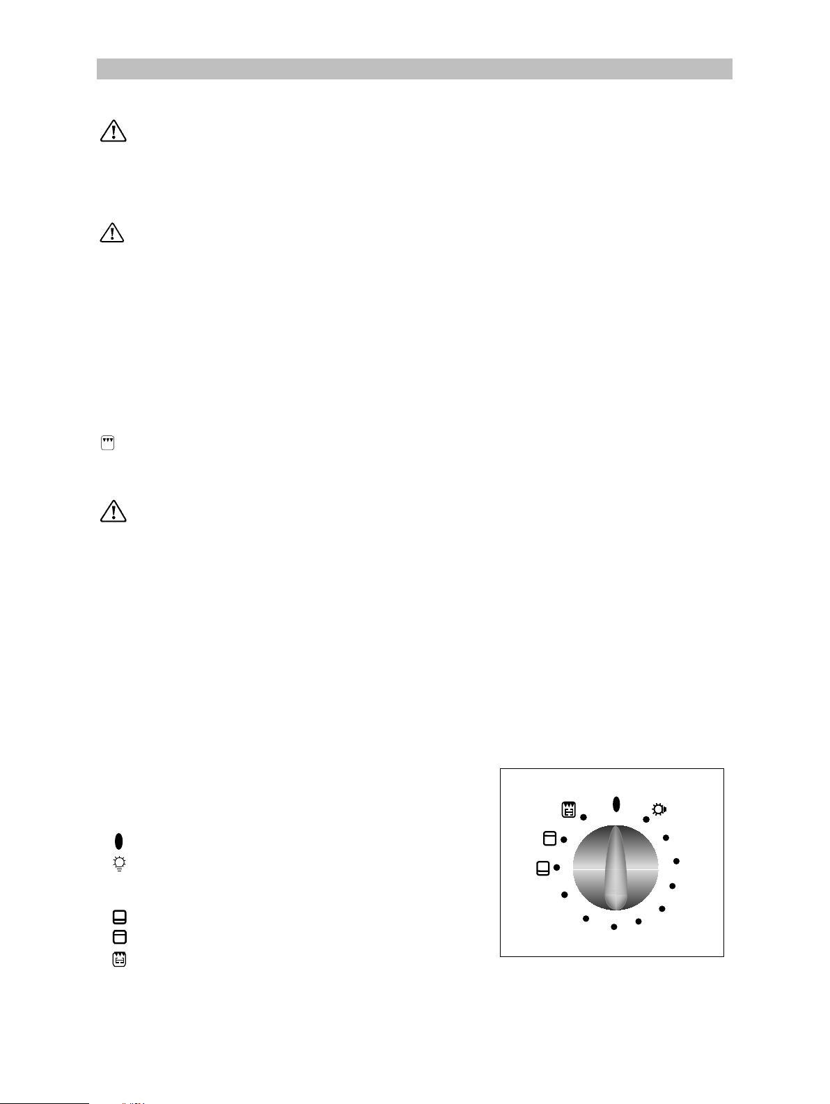
Control knob
The control knob is used to select the desired
temperature and to select either the grill or oven
function.
Explanations of symbols:
Off positions
Oven light
50-250 Range of temperature regulation for
vconventional cooking
Bottom heating element
Top heating element
250
200
50
100
150
Grill
To select the temperature turn the knob
clockwise until the pointer indicating the desired
temperature between 50°– 250°C.
The temperature will be kept constant by the
thermostat.
6
fig. 1
Page 7
Cooking in the oven
Traditional cooking
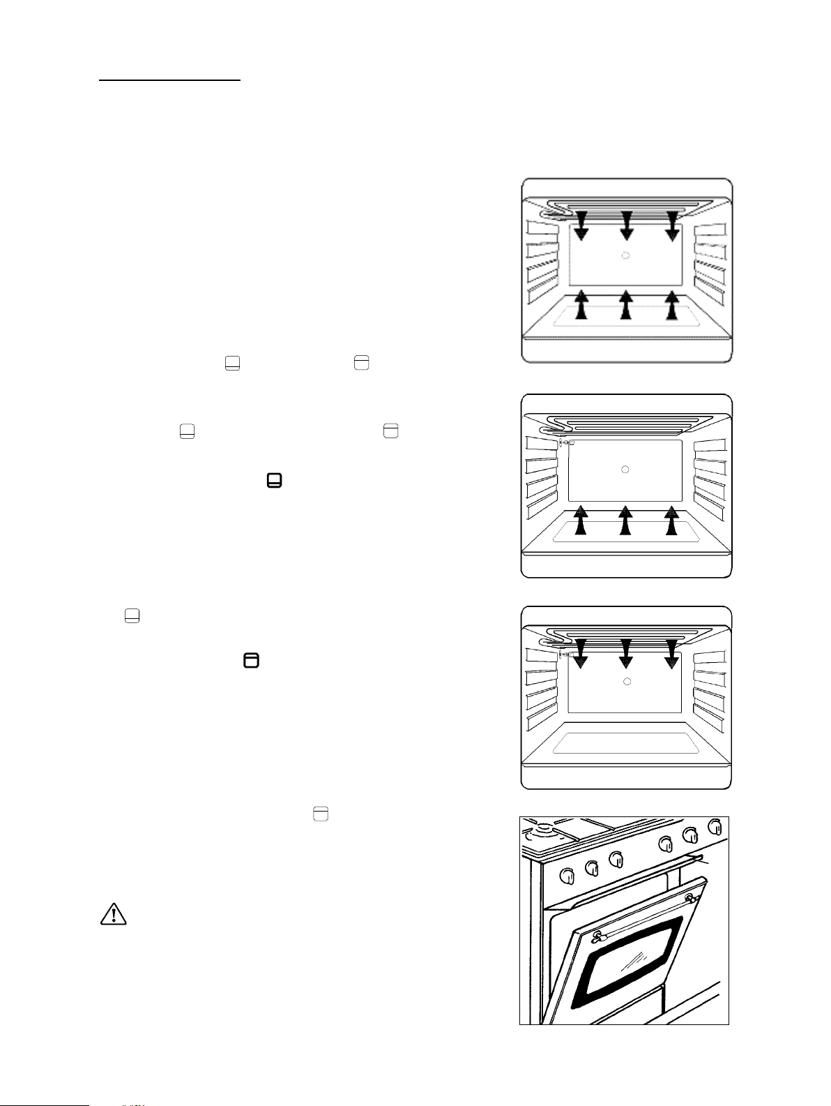
Traditional cooking is made by natural convection
of heated air (fig. 2).
It is necessary to pre-heat the oven.
How to proceed ?
For small cakes, pastry, Victoria sandwich.
1. Preheat the oven the thermostat on position
chosen for cooking:
- about 8 min. for position 50°C to 150°C;
- about 15 min for position 175°C to 250°C;
2. Insert the meal
If you want heat to come from the bottom or heat
coming from the top, turn the control knob to the
appropriate symbol
heat).
Under these circumstances the temperature is
fixed and will never exceed about 215ºC in the
bottom heat
too.
and in the top heat position
(bottom heat) or (top
fig. 2
Bottom heating element
The heat comes from the bottom of the oven only
(fig.3). This position of the thermostat is
recommended for pizza and fruit pies.
Preheating is necessary.
How to proceed ?
1. Preheat the oven the thermostat on position
for about 10 min.
2. Insert the food.
Top heating element
It is a radiant cooking. The heat comes from the
top of the oven only (fig.4). This position of the
thermostat is recommended for warning up the
cooked meals.
It is not necessary to preheat the oven.
How to proceed ?
1. Insert the meal on the 3
2. Turn the thermostat on position
rd
level ( fig.6 ).
.
Using the Electric Grill
Electric grill
fig. 3
fig. 4
A
When grilling, the accessible parts of the
appliance are hot and the appliance should not
be left unsupervised. Take care that children
do not play near it. While the grill is operating
leave the oven door half open and put the grill
deflector “A” into place (fig. 5). During use the
appliance becomes hot. Care should be taken
to avoid touching heating elements inside the
oven, or the grill deflector.
fig. 5
7
Page 8
The grill is used for grilling all kind of meat which
remain tender, toast or browning dishes already
cooked.
Slide the dripping pan under the grid on the
lowest shelf to collect the juice and fat.
For turning off the heating elements.
Turn the knob anticlockwise to position Off “
”.
Grilling
Heat comes from the top of the oven. It is suitable
for grilling meat (beef bacon, pork bacon …) that
remains tender, for toast or to brown dishes
already cooked.
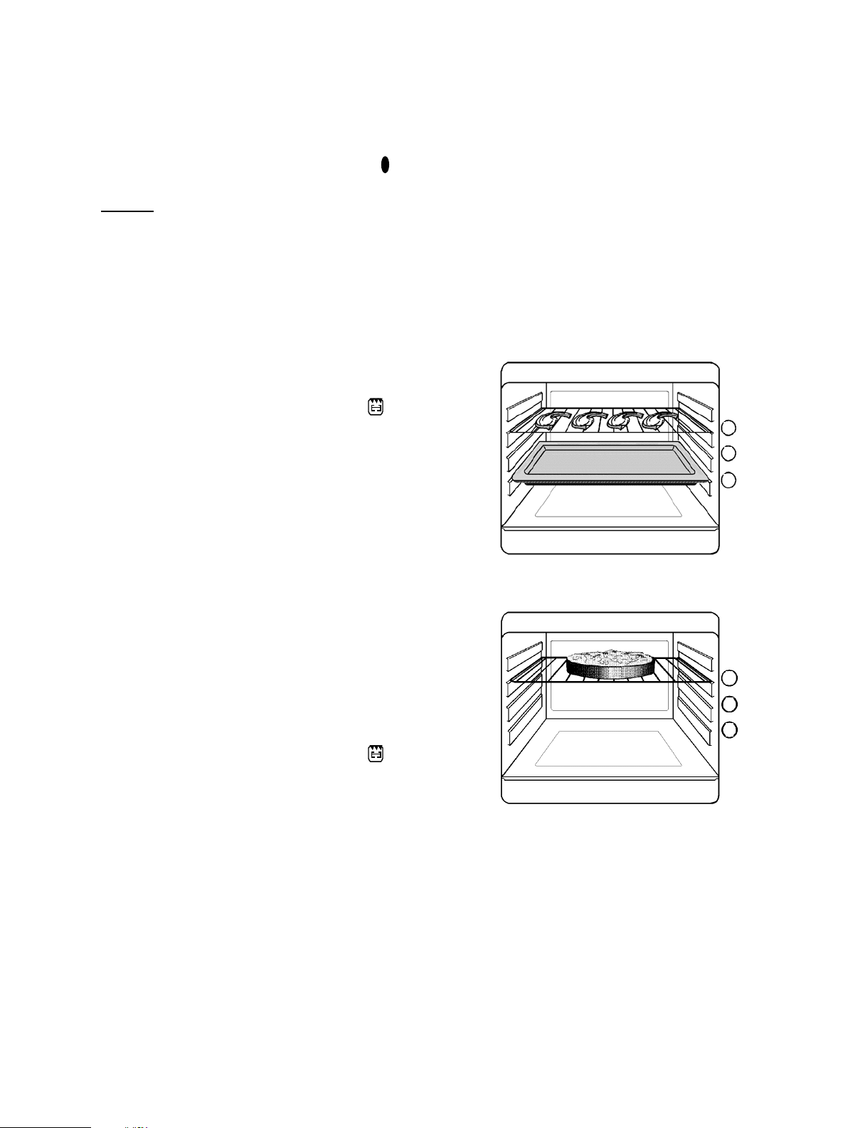
Grilling
• Prepare the meat to be grilled, lightly brush it
with oil on both sides.
• Place it on the trivet.
• Put the grill deflector in place.
• Turn the oven knob to the grill position
.
• Put the dripping pan in level 1.
• Slide the shelf into level 2 or 3 depending on
the thickness of the meat to be grilled.
• Use level 3 for the thin pieces to be grilled
(toast, pork bacon, sausage, small fish…)
• Use level 2 for thick pieces of meat to be
grilled (beef bacon, large fish, poultry).
• When the first side is brown, turn the meat
without pricking it in order that the juices are
not lost.
• Grill the second side.
• Salt when ending the cooking.
Cooking time has to determined by the thickness
of the piece to be grilled not by its weight.
Browning
• Fit the grill deflector.
• Turn the oven knob to the grill position
• Place the dish on the grid and slide it in level 2
or 3.
• Leave the dish under the grill for a few minutes.
.
3
2
1
fig. 6
3
2
1
fig. 7
Oven Thermostat pilot light
This light will illuminate when a temperature is
selected and remain lit until the selected
temperature has been reached. It then cycles on
and off to indicate that the temperature is being
maintained.
8
Page 9
Rotisserie
When using the rotisserie, the accessible
parts of the appliance are hot and the
appliance should not be left unsupervised.
Take care that children do not play near it.
While the rotisserie is operating leave the door
half open and put the grill deflector “A” in
place. After use the rotisserie and its support
are hot, use oven gloves to remove food.
The rotisserie can be used for either spit
roasting meat or for kebabs and smaller pieces
of meat.
How to use the rotisserie
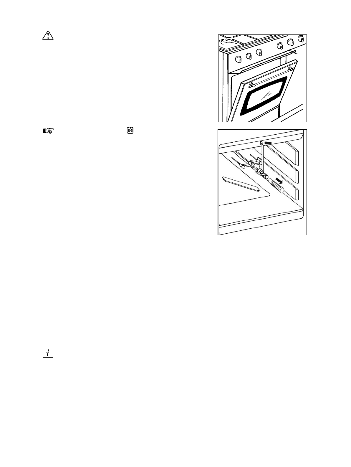
1. Open the oven door and put grill deflector in
place. Slide the meat on the skewer,
making sure that the fork nearest the handle
is in place and that the meat is central.
2. Push on the second fork and tighten both
forks.
3. Push the skewer into the motor shaft in the
back panel and locate the handle end in the
support bracket, then fit the bracket into the
slot in the top of the front frame. See fig. 9.
4. Place the grill pan in a lower shelf position.
5. Remove the handle and close the door so
that it is contact with the deflector.
6. Select grill with the function control knob and
check that the spit is rotating.
7. When the food is cooked, switch off the grill
and refit the handle. Remove the skewer
from the motor, after releasing the front
support bracket. It is advisable to remove
the grill pan at the same time, to ensure that
any dripping fat is contained in the pan.
8. It is advisable to wear protective oven gloves
at all times when using the rotisserie, as
very high temperatures exist in the area of
the grill.
A
fig. 8
fig. 9
The maximum weight permitted on the
rotisserie is 4·5 kg.
Hints and Tips
Condensation and steam
When food is heated it produces steam in the
same way as a boiling kettle. The oven vents
allow some of this steam to escape. However,
always stand back from the oven when
opening the oven door to allow any build up of
steam or heat to release.
If the steam comes into contact with a cool
surface on the outside of the oven, e.g. a trim, it
will condense and produce water droplets. This
is quite normal and is not a fault with the oven.
To prevent discolouration, regularly wipe away
condensation and also soilage from surfaces.
Cookware
Use any ovenproof cookware, which will
withstand temperatures of 250
Oven dishes, etc. must not be placed
directly on the oven base.
°
C.
9
Page 10
Oven Cooking
• Turn off the oven 5 minutes before the end of
cooking time, and use residual heat to
complete the cooking.
• The thickness, the material and the colour of
the pan will influence the cooking results.
• When cooking, certain dishes increase in
volume, ensure the pan is large enough.
• To prevent fat dripping when roasting use tall
rim pans proportional to the item being
roasted.
• Prick the skin of poultry and sausages with a
fork before cooking to avoid spitting.
• Use heatproof glass dishes for soufflés.
The effects of dishes on cooking results
Dishes and tins vary in their thickness,
conductivity, colour, etc. which affects the way
they transmit heat to the food inside them.
A Aluminium, earthenware, oven glassware and
bright shiny utensils reduce cooking and base
browning.
B Enamelled cast iron, anodised aluminium,
aluminium with non-stick interior and coloured
exterior and dark, heavy utensils increase
cooking and base browning.
Oven thermostat pilot light
The oven pilot light illuminates as soon as the
thermostat control knob is turned on and remains
lit while the oven / grill is in operation.
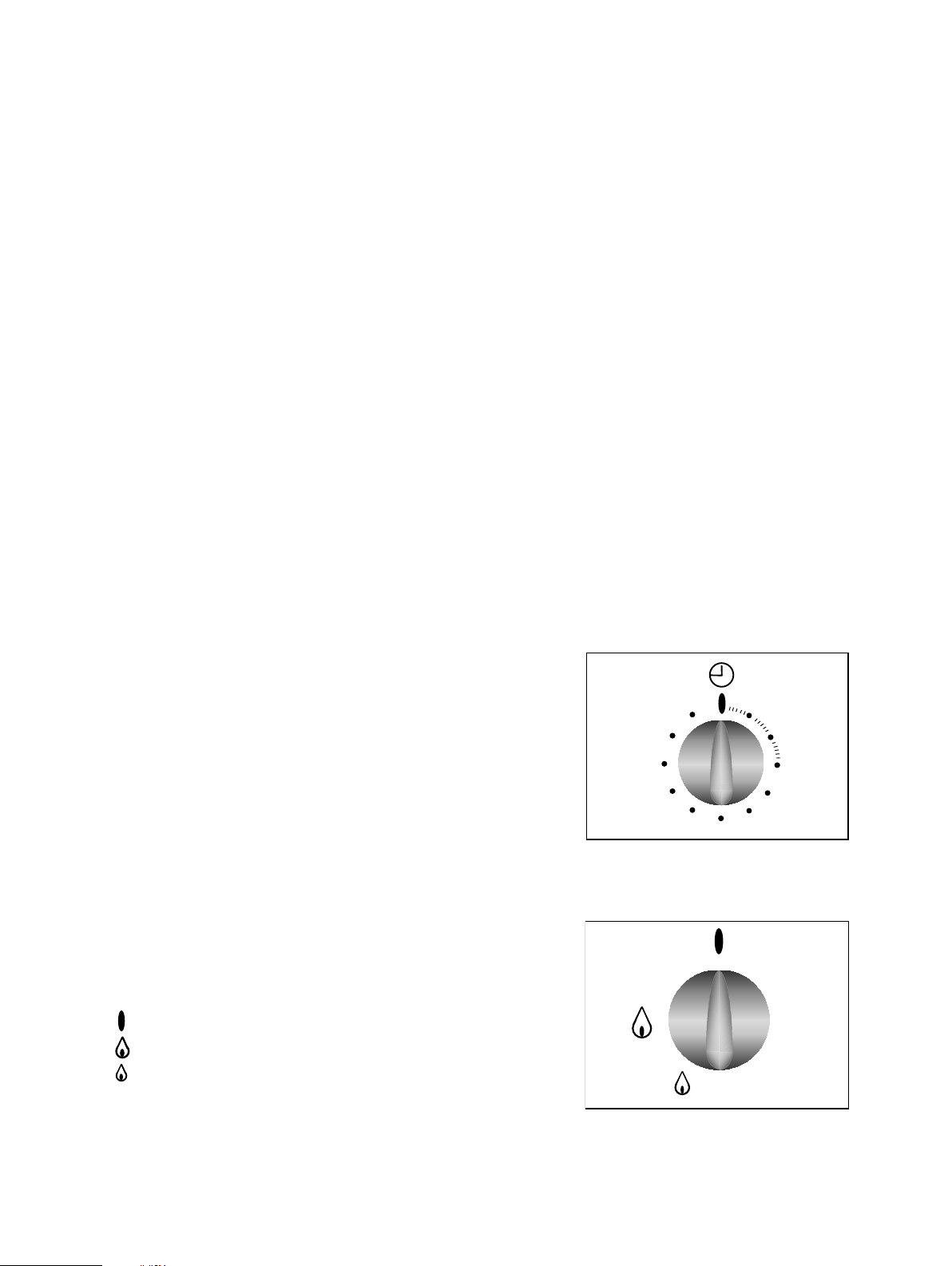
Timer (Minute Minder)
Turn the control knob (fig. 10) clockwise to the
maximum position and than turn it back to the
position corresponding to the period of time
necessary for the cooking.
At the end of the time selected an acoustic signal
sounds which stops automatically. The timer does
not interrupt the operation of the oven at the end of
the set time.
Using the Hob
The Hob Burners
To the symbol on the knob corresponds a symbol
on the control panel (fig. 11)
Off
Maximum level
Minimum level
fig. 10
45
50
40
35
55
30
5
10
15
20
25
Use the maximum level for boiling and the
minimum for simmering.
Always choose positions between the minimum
and maximum, never between maximum and off.
10
fig. 11
Page 11
Ignition of the burners
(
)
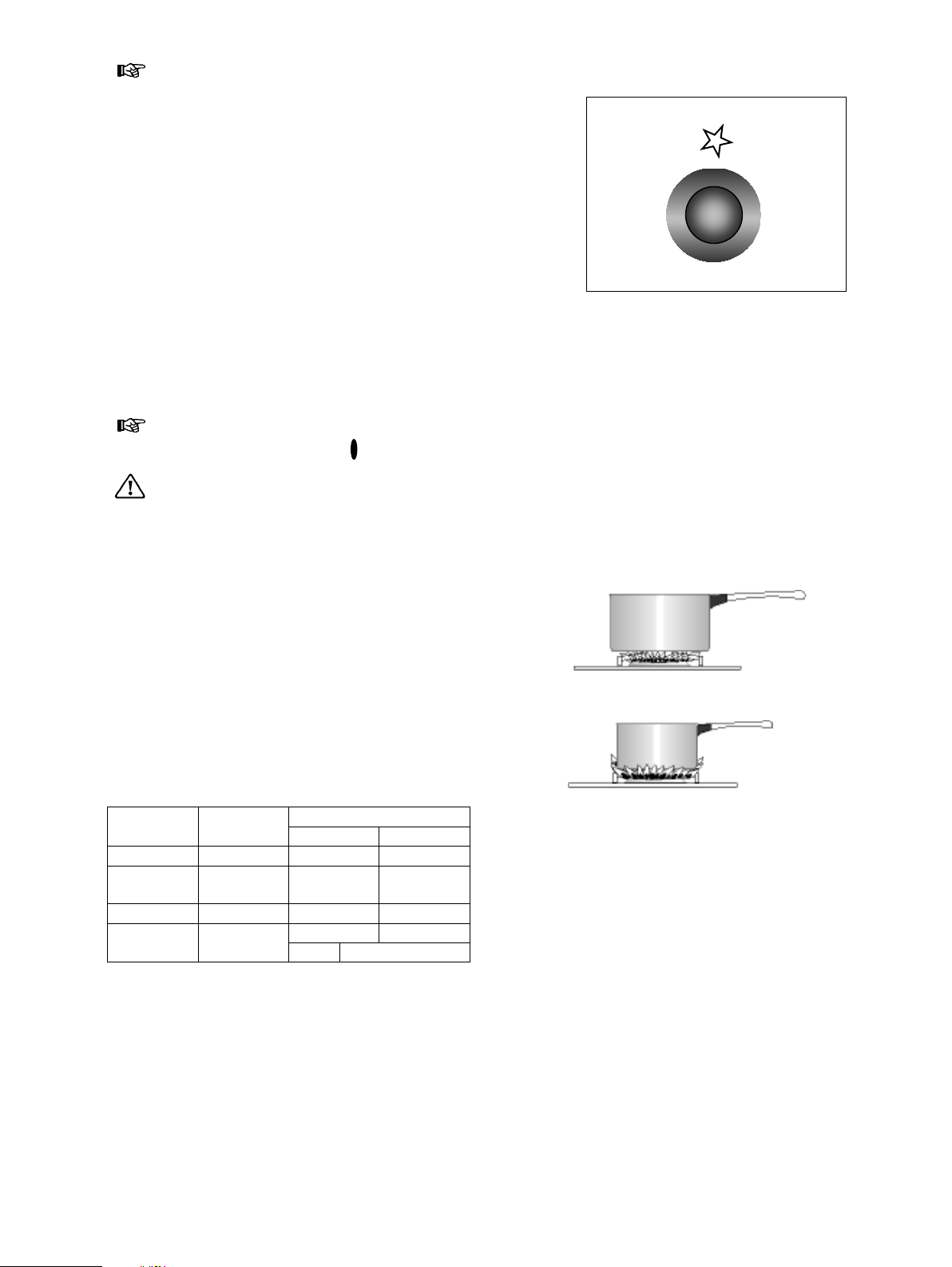
• Push the knob and turn it left to the “large flame”
symbol.
• At the same time, push the electronic
ignition knob (see fig 12). Keep it pushed until
the gas ignites (1 spark / second).
or
Mains Failure
• Push the corresponding knob in completely
and turn it left to the “large flame” symbol and
ignite with a match.
• Release the knob and watch that the burner
has ignited. Upon ignition, adjust the flame as
required.
• If for any reason the flame should extinguish
turn off the relevant control knob, leave for at
least one minute and then re-ignite.
Extinguishing of burners
Turn the knob clockwise to mark «
».
Do not put anything on the hob that is
liable to melt.
Selecting the Correct burner
Above every knob there is a symbol for the
corresponding burner.
For good cooking results, always choose pans,
which correctly fit to the diameter of the burner
used (see fig. 13). Choose thick, flat bottom pots.
We recommend the flame is lowered as soon as
the liquid starts boiling.
For a correct ignition always keep the burner ring
and the spark plugs clean.
fig. 12
Correct use
Incorrect use
Power waste
The following diameter pans can be used:
Burner Power Diameter (mm)
(kW) min. max.
Rapid 2,60 165 260
SemiRapid
2,00 140 220
Auxiliary 1,00 120 160
260 340Rapid Fish
oval 180 x 280
Kettle
2,60
fig. 13
11
Page 12
Accessories delivered with the
appliance
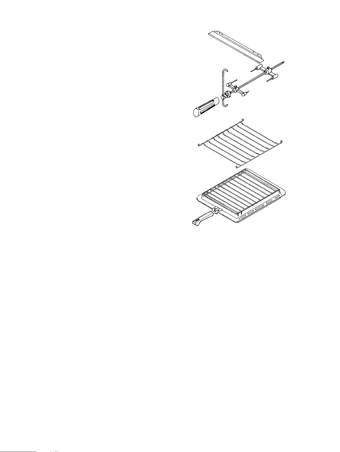
The following accessories are supplied with your
appliance (fig. 14) :
• 1 trivet.
• a removable handle
• a dripping pan / roasting tray with roasting grid
in it.
The dish has to be put in the middle of the shelf to
balance the weight.
• a grill deflector
It is used for when using the grill or the turn-spit.
• a turn spit made up of:
- 2 forks
- 1 spit
- 1 handle
- 1 spit support
In addition to the accessories supplied we
recommend you only use heatproof dishes/pans
(according to the manufacturer’s instructions).
• a shelf for the storage compartment
Storage Compartment
Can be used for kitchen utensils or different
accessories.
IMPORTANT: Never use for storing
inflammable materials.
THE STORAGE COMPARTMENT MUST NEVER
BE USED TO STORE LPG GAS BOTTLES,
AEROSOL CANS OR ANY PRESSURISED
CONTAINERS.
fig. 14
12
Page 13
MAINTENANCE AND CLEANING
The oven should be kept clean at all
times. A build-up of fats or other
foodstuffs could result in a fire,
especially in the grill pan.
Before cleaning, ensure all control
knobs are in the OFF position, and the
appliance has cooled completely.
Before any maintenance or cleaning can
be carried out, you must DISCONNECT
the cooker from the electricity supply.
Cleaning materials
Before using any cleaning materials on your
oven, check that they are suitable and that their
use is recommended by the manufacturer.
Cleaners that contain bleach should NOT
be used as they may dull the surface
finishes. Harsh abrasives should also be
avoided.
External cleaning
Regularly wipe over the control panel, oven door
and door seal using a soft cloth well wrung out in
warm water to which a little washing up liquid has
been added.
To prevent damaging or weakening the
door glass panels avoid the use of the
following:
• Household detergent and bleaches
• Impregnated pads unsuitable for non
stick saucepans
• Brillo/Ajax pads or steel wool pads
• Chemical oven pads or aerosols
• Rust removers
• Bath/Sink stain removers
Oven Cavity
The enamelled oven cavity is best cleaned whilst
the oven is still warm.
Wipe the oven over with a soft cloth soaked in
warm soapy water after each use. From time to
time it will be necessary to do a more thorough
cleaning, using a proprietary oven cleaner.
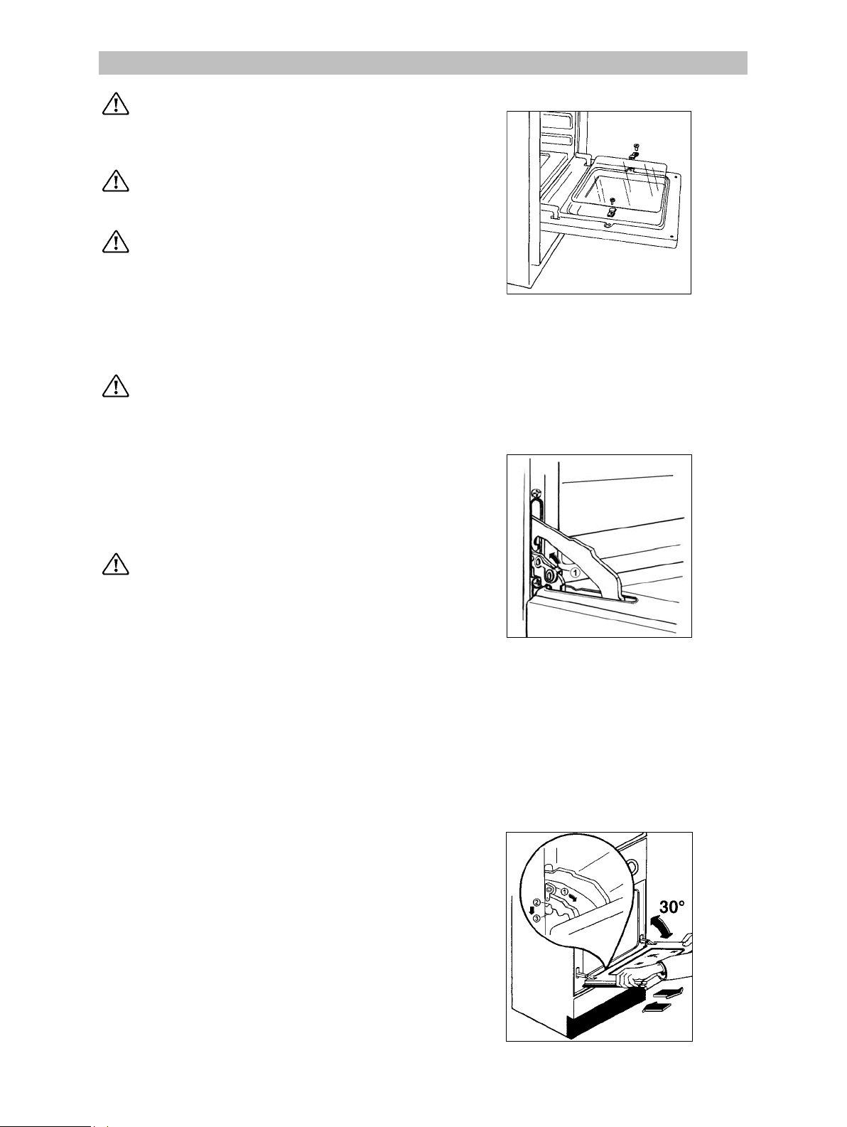
Removing the Oven Door
1. Open the door completely.
2. Turn the two locking levers (1) on the hinge
arms fully upwards.
3. Hold the oven door at the sides using both
hands and close the door partially to a 30
angle.
4. Lift the door and pull out.
Hanging the Oven Door
1. Hold the oven door at the sides using both
hands and hold the door at an angle of
approx 30
2. Introduce and then push the hinges into the
cut-outs on the front of the oven, ensuring
that the supports (2) of the hinge arms are
correctly placed in the cut-outs (3) of the
hinge support.
3. Turn the locking levers (1) fully downwards.
o
.
o
Oven Door Glass
The internal oven door glass can be removed for
cleaning. For this purpose remove the 2 fixing
screws. Clean the outer and inner door glass
using warm soapy water. Should the inner door
glass become heavily soiled it is recommended
that a cleaning product such as Hob Brite, or Bar
Keepers Friend be used.
Always support the door while removing the
glass panel as the door may spring closed due to
its lighter weight.
13
Page 14
DO NOT clean the oven door while the
glass panels are warm. If this precaution is
not observed the glass panel may shatter.
If the door glass panel becomes chipped or
has deep scratches, the glass will be
weakened and must be replaced to prevent
the possibility of the panel shattering.
Contact your local Service Centre who will
be pleased to advise further.
IMPORTANT: The inner door glass must be in
place when using the oven.
Hob
After every use wipe with a soft cloth well wrung
out in warm water to which a little washing up
liquid has been added, avoiding any leakage
through the holes of the hob. Rinse and dry with
a soft cloth.
To remove more stubborn stains, wet and leave
to dissolve, do not scratch and avoid the use of
abrasive or caustic products that could damage
the enamel.
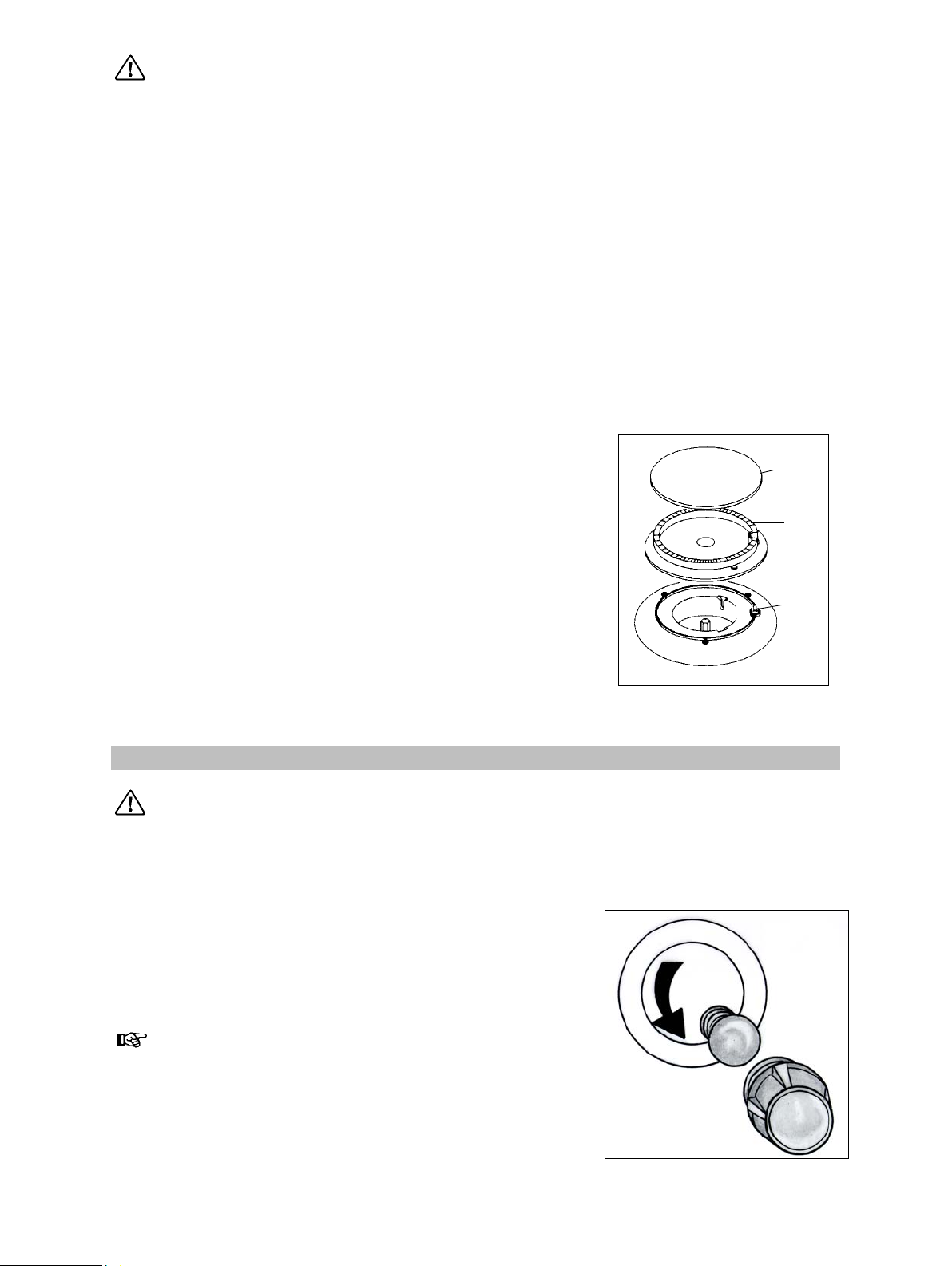
Burner cap
Burners
The burner caps and crowns can be removed
for cleaning.
Wash the burners caps and crowns using hot
soapy water, and remove marks with a mild
paste cleaner. A well-moistened soap
impregnated steel wool pad can be used with
caution, if the marks are particularly difficult to
remove.
After cleaning, be sure to wipe dry with a soft
cloth.
OVEN BULB REPLACEMENT
Ensure that the appliance is switched off
and disconnected from the electricity supply
before replacing the bulb to avoid possibility
of an electric shock.
If the oven bulb needs replacing, it must comply
with the following specifications:
Electric Power: 15W
Electric Rate: 230/240V (50Hz)
Resistant to temperatures of: 300ºC
Connection Type: E14
fig. 18
Burner
ring
Ignition
To replace the faulty bulb.
1. Turn the glass cover anti clockwise and
remove.
2. Remove the faulty bulb and replace with a
new one.
3. Refit the glass cover.
4. Reconnect the appliance to the electricity
supply.
14
fig. 31
Page 15

SOMETHING NOT WORKING
If the appliance is not working correctly, please carry out the following checks, before contacting your
local Service Centre.
IMPORTANT: If you call out an engineer to a fault listed below, or to repair a fault caused by
incorrect use or installation, a charge will be made even if the appliance is under guarantee.
Symptoms Solutions
1. No burner ignition
2. The gas ring burns unevenly
3. The oven does come on
4. Cooking results are not satisfactory
5. The oven smokes
6. The oven does not work
Check that:
• Gas supply is completely open
• The position of the gas pipe is correct
• The burner is not wet
• The burner cap and ring burner have been
replaced correctly after cleaning
Check that:
• The main jet is not blocked and the ring
burner is clean of food particles
• The burner cap and ring burner have been
replaced correctly after cleaning
Check that:
• a cooking function/temperature has been
selected;
Check that:
• the thermostat is set correctly;
• the correct cooking time is used;
Check that:
• the oven does not need cleaning;
• the meal does not overflow;
• there are no excessive fat / juice deposits on
the oven sides.
Check that:
• the appliance is not unplugged;
• there is no power break.
• the fuse has not failed.
If after these checks, the appliance still does not operate correctly, contact your local Service Force
Centre. When you contact the Service Force Centre you will need to give the following details:
1. Your name, address and post code.
2. Your telephone number
3. Clear and concise details of the fault
4. The model and serial number of the appliance (found on the rating plate*)
5. The purchase date
* The rating plates can be found on the front
Please note that a valid purchase receipt or guarantee documentation is required for inguarantee service calls.
and back of the cooker.
15
Page 16

SERVICE AND SPARE PARTS
In the event of your appliance requiring service, or if you wish to purchase spare parts, please contact
your local Service Force Centre by telephoning:-
08705 929929
Your telephone call will be automatically routed to the Service Force Centre covering your post code
area.
For the address of your local Service Force Centre and further information about Service Force,
please visit the website at www.serviceforce.co.uk
Before calling out an engineer, please ensure you have read the details under the heading
“Something Not Working” and have the model number and purchase date to hand.
In-guarantee customers should ensure that the checks under the heading “Something Not
Working” have been made as the engineer will make a charge if the fault is not a mechanical or
electrical breakdown. Please note that it will be necessary to provide proof of purchase for any
in-guarantee service calls.
Moffat has an agreement with Electrolux who will undertake all servicing requirements for your
appliance.
CUSTOMER CARE
For general enquiries concerning your Parkinson Cowan appliance and or for further information on
our products, contact our Customer Care Department by letter or telephone as follows:
Customer Care Department
Parkinson Cowan
55-77 High Street
Slough
Berkshire SL1 1DZ
Tel: 08705 950950 (*)
(*) calls to this number may be recorded for training purposes.
16
Page 17

GUARANTEE CONDITIONS
Standard Guarantee Conditions
We Parkinson Cowan undertake that if, within 12 months of the date of the purchase, this Parkinson
Cowan appliance or any part thereof is proved to be defective by any reason only of faulty
workmanship or materials, we will, at our option, repair or replace the same FREE OF ANY CHARGE
for labour, materials or carriage on condition that:
• The appliance has been correctly installed and used only on the electricity supply stated on the
rating plate.
• The appliance has been used for normal domestic purposes only, and in accordance with the
manufacturer's instructions.
• The appliance has not been serviced maintained, repaired, taken apart or tampered with by any
person not authorised by us.
• All service work under this guarantee must be undertaken by a Parkinson Cowan Service Force
Centre.
• Any appliance or defective part replaced shall become the Company's property.
• This guarantee is in addition to your statutory and other legal rights.
Home visits are made between 8.30am and 5.30pm Monday to Friday. Visits may be available
outside these hours, in which case a premium will be charged.
Exclusions
This guarantee does not cover:
• Damage or calls resulting from transportation, improper use or neglect, the replacement of any light
bulbs or removable parts of glass or plastic.
• Costs incurred for calls to put right an appliance which is improperly installed or calls to appliance
outside the United Kingdom.
• Appliances found to be in use within a commercial or similar environment, plus those, which are
the subject to rental agreements.
• Products of Parkinson Cowan manufacture which are not marketed by Parkinson Cowan.
European Guarantee
If you should move to another country within Europe then your guarantee moves with you to your new
home subject to the following qualifications:
• The guarantee starts from the date you first purchased your product.
• The guarantee is for the same period and to the same extent for labour and parts as exist in the
new country of use for this brand or range of products.
• This guarantee relates to you and cannot be transferred to another user.
• Your new home is within the European Community (EC) or European Free Trade Area.
• The product is installed and used in accordance with our instructions and is only used
domestically, i.e. a normal household
• The electrical supply complies with the specification given in the rating label.
• The product is installed taking into account regulations in your new country.
Before you move, please contact your nearest Customer Care Centre, listed below, to give them
details of your new home. They will then ensure that the local Service Organisation is aware of your
move and able to look after you and your appliances.
France Senlis +33 (0) 3 44 62 20 13
Germany Nürnberg +49 (0) 800 234 7378
Italy Pordenone +39 (0) 800117511
Sweden Stockholm +46 (0) 20 78 77 50
UK Slough +44 (0) 1753 219898
17
Page 18

INSTRUCTIONS FOR THE INSTALLER
d
d
d
d
d
SAFETY ADVICE
• Before installation ensure that the local
distribution conditions (gas type and pressure)
and the pre-setting of the appliance are
consistent.
• This appliance must be installed only in a
room with good ventilation.
• This appliance must not connected to a flu. It
has to be installed and connected in
accordance with the rules in force. Special
attention should be paid to the applicable
disposal concerning ventilation.
• The adjacent furniture panels have to be heat
proof or protected by such material.
• The working conditions of this appliance are
mentioned on the rating plate.
Connection to gas supply.
Check that the gas flow and the diameter of the
supply pipe is sufficient to supply all the
appliances of the installation.
• Check that all connections are tight.
• Install an accessible and visible gas tap to
isolate the appliance.
- Installation of flues and ventilation for gas
appliances of rated input not exceeding
60 kW (1
st
, 2
n
and 3
r
family gases) – Part
2 Specification for installation of
ventilation for gas appliances – BS 5440;
- Gas burning appliances – Part 3 Domestic
cooking appliances burning gas – BS
5386;
- Specification for installation of low
pressure gas pipe work of up to 20mm
(R1) in domestic premises (2
n
family gas)
– BS 6891;
- Pipe threads for tubes and fittings where
pressure-tight joints are made on the
threads (metric dimensions) – BS 21:
1985;
- Flexible hoses, end fittings and sockets
for gas burning appliances – BS 669;
Installation of domestic gas cooking
appliances (1
st
, 2
n
and 3
r
family gases) – BS
6172: 1990;
Electrical Connection
Check that:
• the supply provides adequate power;
• the connecting cable is in good condition;
18
Page 19
TECHNICAL FEATURES
Free standing Classe 1
Hob Pan support
Front right
Back right
Front left
Back left
Middle (fish)
Burners ignition
Oven Oven
Oven power
Grill
Grill burner power
Oven light
Total rating 1815 W
Accesories Trivet
Removable handle
Dripping pan / roasting tray
Roasting grid
Grill deflector
Rotisserie
Shelf
Legs
Supply Rated voltage
Rated frequency
Total cooker rating 1819,6 W
Enamelled
Rapid
Auxiliary
Rapid
Semirapid
Rapid
2600 W
1000 W
2600 W
2000 W
2600 W
0,6 W
electric
1700 W
electric
1800 W
Lamp 15W type E14
4 W
240 V
50 Hz
Dimensions Height
Width
Depth
This appliance complies with the
following EEC Directives :
90/683 ; 73/23 (Low Voltage Directive)
and subsequent modifications,
89/336 (Electromagnetical Compatibility
Directive) and subsequent modifications,
90/396 (Gas Appliance Directive) 93/68
(General Directives) and subsequent
modifications.
900 mm
850 mm
600 mm
19
Page 20
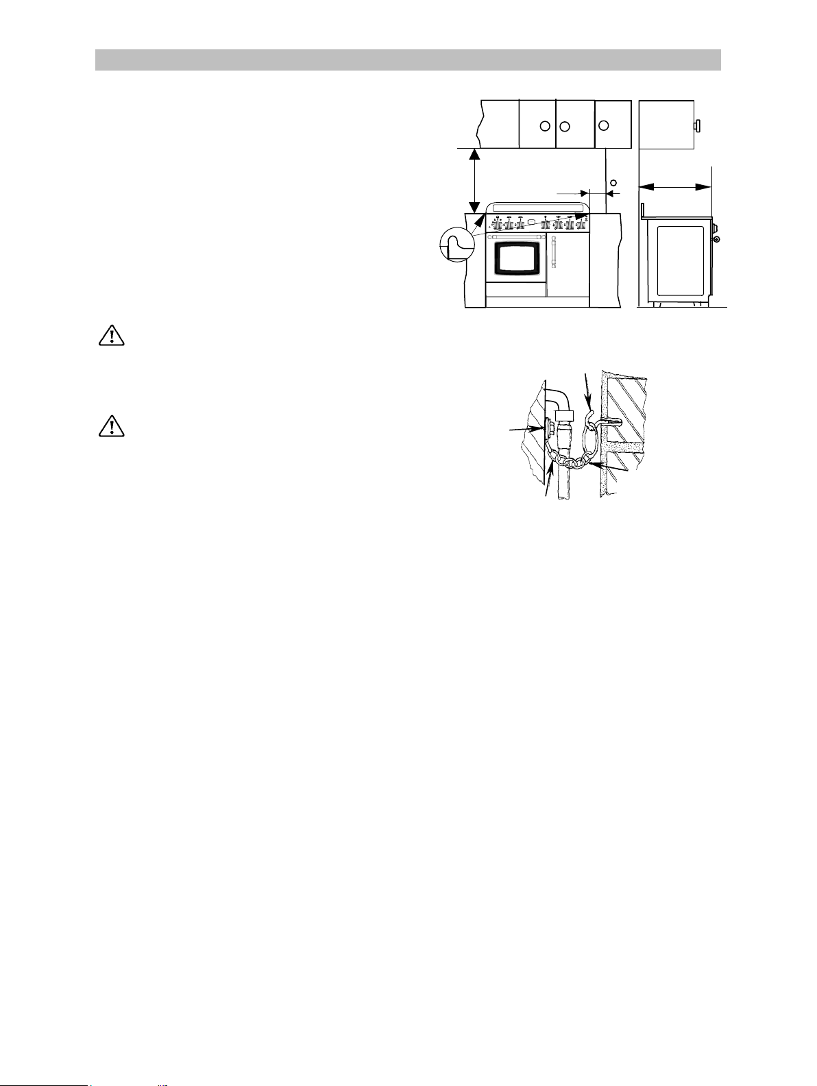
LOCATION
3
3
2
3
3
3
3
The cooker has been registered as a “Class X”
appliance according to Fire Risk Regulations.
Any adjacent cabinets or walls must not exceed
the cooker’s height.
The cooker may be located in a kitchen, a
kitchen/diner or bed sitting room, but not in a
bathroom, shower room or garage.
The minimum distance combustible material can
be fitted above the cooker in line with the edges
of the cooker is 660mm (see fig.20).
660 mm
150 mm
5
55
PARKINSON
50
COWAN
50
10
45
250
100
200
150
403020
35
15
25
610 mm
L.P.G. cookers or ovens MUST NOT be
installed below ground level, i.e. in a
basement, or aboard any boat, yacht or
other vessel.
The cooking appliance must be fitted
with a stability chain firmly secured to
the wall (see fig 21).
Ventilation
The room containing the cooker should have an
air supply in accordance with B.S. 5440: Part 2:
Current Editions.
The following requirements for ventilation must
be met.
The cooker should not be installed in a bed
sitting room with a volume of less than 20m
is installed in a room of volume less 5m
vent of effective area of 110cm
is required; if it is
installed in a room of volume between 5m
10m
, an air vent of effective area 50cm2 is
required, while if the volume exceeds 11m
vent is required. However, if the room has a door,
which opens directly to the outside, no air vent is
required even when the volume is between 5m
and 11m3.
, if it
an air
and
no air
fig. 20
Firmly fix
chain to rear
of cooker
fig. 21
Stability
chain
Stability
hook
Chain to be as
short as
practicable
If there are other fuel burning appliances in the
same room, B.S. 5440: Part. 2: Current Editions
should be consulted to determine the requisite air
vent requirements.
20
Page 21
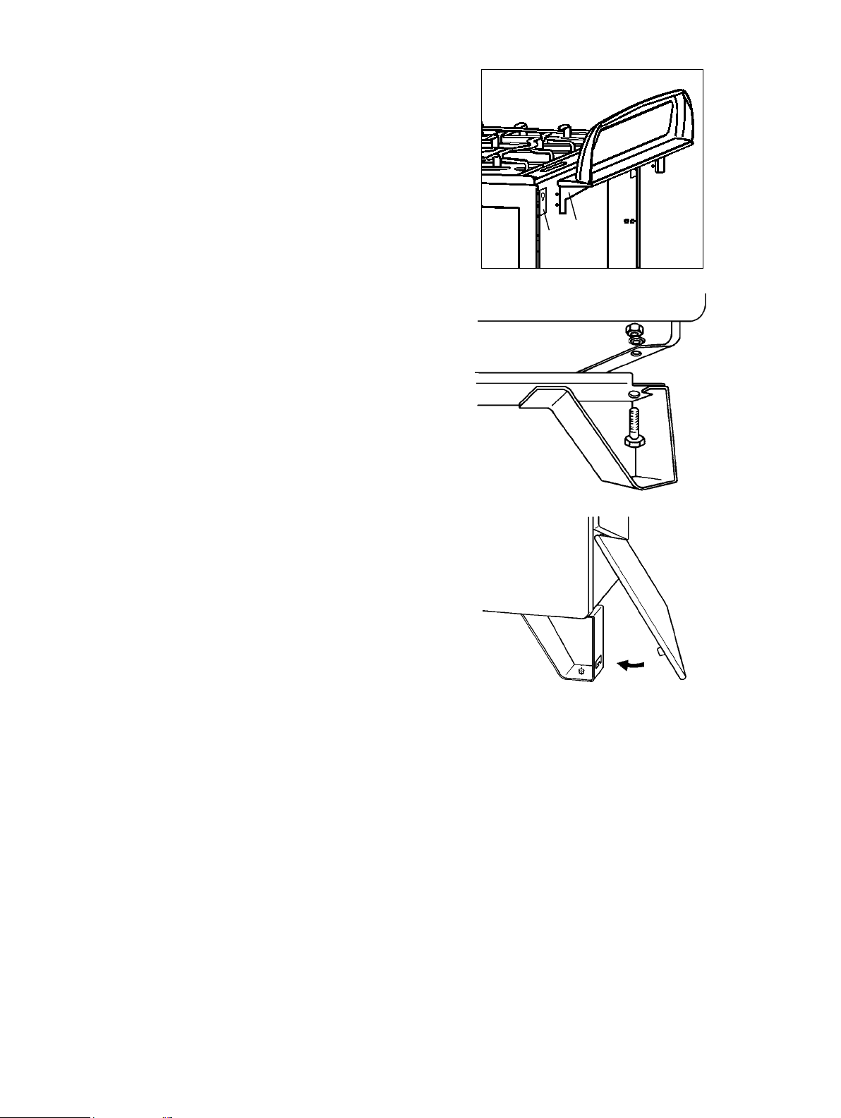
Assembling of back panel
Introduce the screws of the back panel fixing (1)
into the seats of supports (2) and push it
downwards to the bottom of seats (fig. 22).
1
2
Levelling
- Fix the two legs by means of screws and
nuts delivered together with the appliance
(fig. 23).
- Open the storage compartment door.
- Place the top clips of the plinth into the
holes as shown in fig. 24.
- Push the bottom of the plinth against the
legs ensuring that the tongues on the plinth
locate into the slots on the front of the legs.
fig. 22
fig. 23
fig. 24
21
Page 22
ELECTRICAL CONNECTION
Any electrical work required to install
this cooker should be carried out by a
qualified electrician or comp etent person, in
accordance with the current regulations.
THIS COOKER MUST BE EARTHED.
The manufacturer declines any liability
should these safety measures not be
observed.
This cooker is designed to be connected to a
240V, 50Hz AC electrical supply.
Before switching on, make sure the electricity
supply voltage is the same as that indicated on
the cooker rating plate. The rating plate is located
on the oven frame.
The cooker is supplied with a 3 core flexible
supply cord incorporating a 13amp plug fitted. In
the event of having to change the fuse, a 13amp
ASTA approved (BS 1362) fuse must be used.
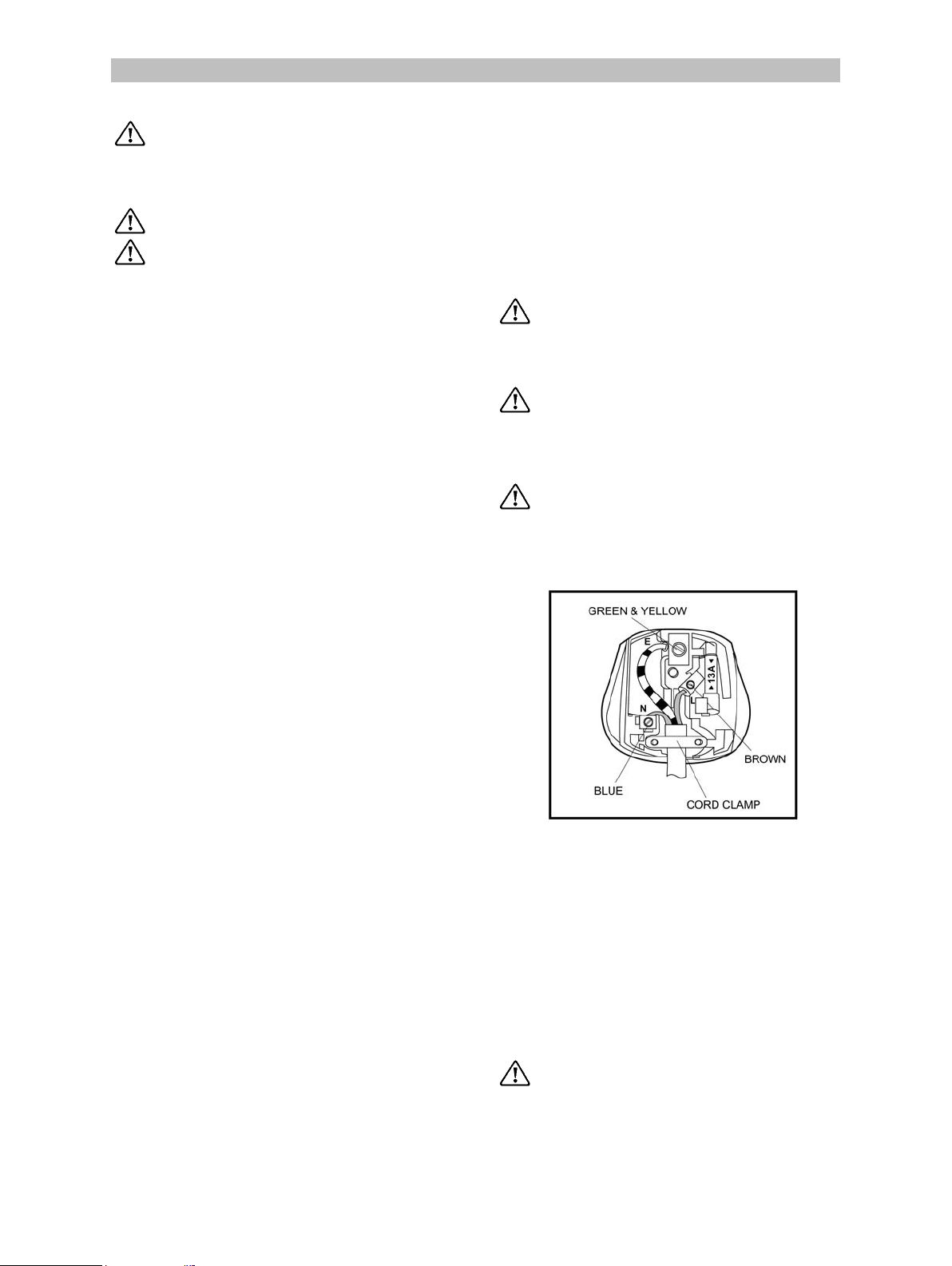
Should the plug need to be replaced for any
reason, the wires in the mains lead are coloured
in accordance with the following code:
Before connecting check that:
• fuse and household electric installation can
carry the load of the appliance (see rating
plate);
• The plug used for connection is easily
accessible when the appliance is installed.
Warning
It is forbidden to route the supply cable
across the back of the oven.
Important
If the supply cable is damaged it must be
replaced by the manufacturer or its service
agent or a similarly qualified person to ensure
safety.
A cut off plug inserted into a 13 amp
socket is a serious safety (shock) hazard.
Ensure that the cut off plug is disposed of
safety.
Green and Yellow
- Earth
Blue - Neutral
Brown - Live
- Connect the green and yellow (earth) wire to
the terminal in the plug which is marked with
the letter 'E' or the earth symbol or coloured
green and yellow.
- Connect the blue (neutral) wire to the
terminal in the plug which is marked with the
letter 'N' or coloured black.
- Connect the brown (live) wire to the terminal
in the plug which is marked with the letter 'L'
or coloured red.
Upon completion there must be no cuts, or stray
strands of wire present and the cable clamp must
be secure over the outer sheath of the cable.
Fuse capacity: 13A
NOTE: The earth wire should be about 2 cm
longer than the live and neutral wires.
Note:
fig. 19
Permanent Connection
The electrical connection should be made using
a double pole isolating switch (cooker control
switch) with at least 3mm contact separation in
all poles. The cable must have conductors of
sufficiently high cross-sectional area to prevent
overheating or deterioration.
The switch must not break the yellow and green
earth cable at any point.
Check on the rating plate the value for the
total connection power for establishing the
fuse power.
22
Ensure that the cooker supply cable
does not come into contact with surfaces
with temperatures higher than 50° C.
Page 23
GAS CONNECTION
Your cooker is delivered adjusted for the kind of
gas stated on the rating plate.
If the appliance is supplied with natural gas and the
pressure for natural gas is 20mbar. The following
methods of connection to the gas supply must be
used:
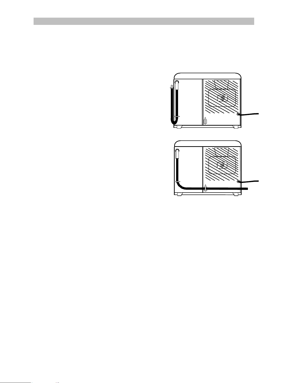
Right Hand Connection (from front)
Ensure that the rubber hose is not in contact with
any part of the hatched area shown in the diagram
and that the loop of the hose when connected is
not in contact with the floor when the appliance is
in position (fig. 25).
Left Hand Connection (from front)
Ensure that the rubber hose is not in contact with
any part of the hatched area shown in the diagram
and the hose is retained in the clamp provided, it
will be necessary to fit the maximum length hose
when using this method (1200mm min) (fig. 26).
fig. 25
fig. 26
23
Page 24
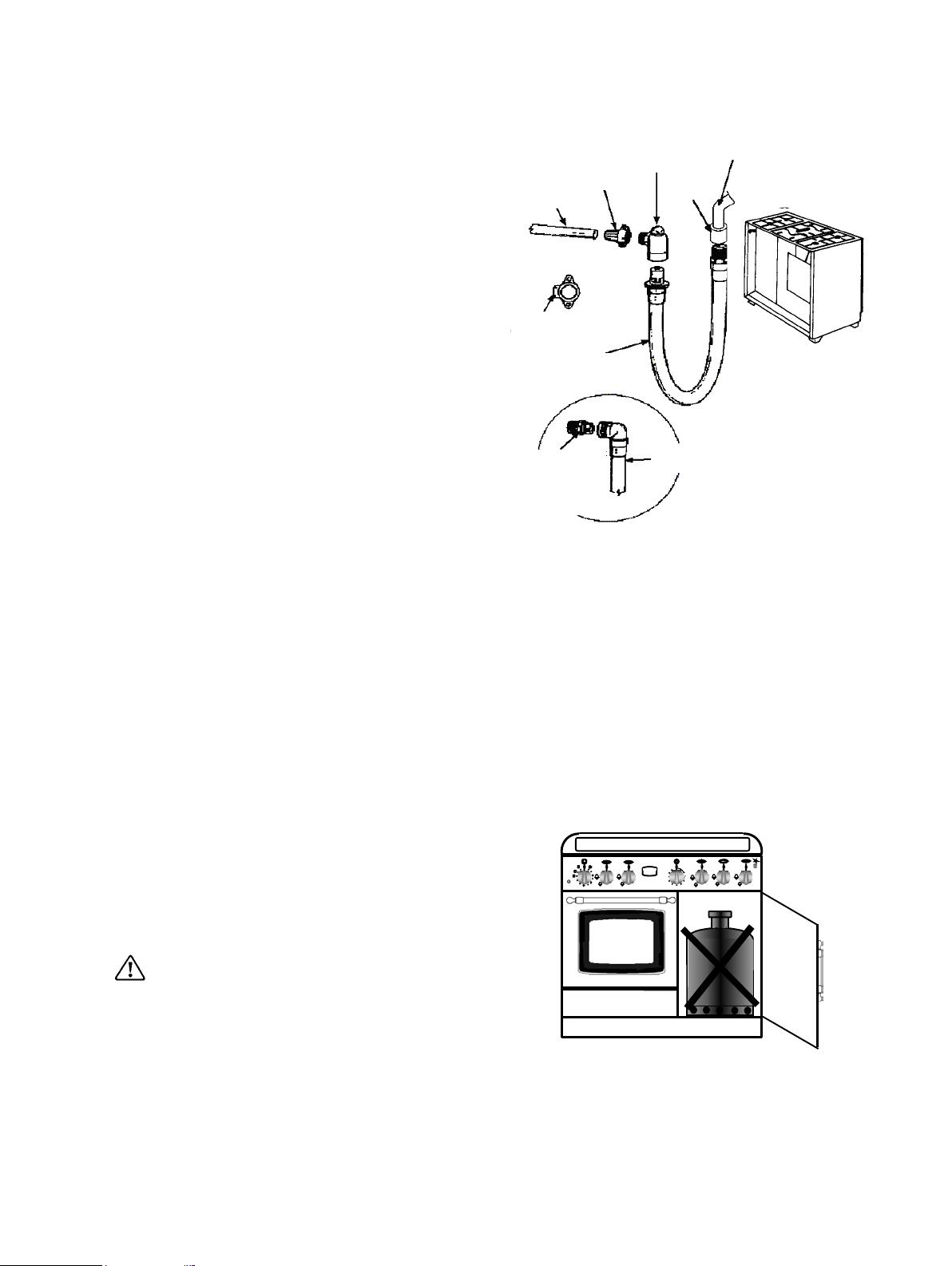
Rigid Connection
Where it is not possible to make the connection
using a rubber hose, a rigid pipe work connection
must be used.
Recommendations when using an appliance
flexible connector are as follows:
- For NATURAL the gas installation pipes to the
termination point shall comply with:
Specification for installation of low-pressure
gas pipe work of up to 20mm (R1) in domestic
premises (2nd family gas) – BS 6891;
Connection shall be by means of an appliance
flexible connector for use with a self-sealing plug-in
device, complying with:
Flexible hoses, end fittings and sockets for gas
burning appliances – BS 669;
- The appliance flexible connector should not be
subjected to undue forces either in normal use
or whilst connected or disconnected; The
socket which the plug of the appliance flexible
connector fits should be permanently attached
to a firmly fixed gas installation pipe and
positioned such that the appliance flexible
connector hose hangs freely downwards (see
fig. 27);
- The appliance flexible connector should be
positioned such that it will not suffer
mechanical damage, e.g. abrasion from the
surrounding kitchen furniture, which may be
moved in use such as a drawer or door, or by
being trapped by any stability device.
Copper pipe
Alternative
backplate
elbow
Cooker hose with
bayonet fixing
Straight bayonet
socket
incorporating
spring loaded
valve
fig. 27
Adaptor
backplate
Right angled
bayonet socket
incorporating
spring loaded
valve
Female
elbow
Cooker hose with
bayonet fixing
Distribuitor
pipe
The plug-in-connector should be accessible for
disconnection after moving the appliance.
Position of the cylinder (propane bottle)
The cylinder must be installed by qualified
personnel, according to the relevant British
Standards.
You must not lay the cylinder in the
storage compartment! The appliance should be
connected to a bottled gas (LPG) externally.
fig. 28
PARKINS
2
24
Page 25
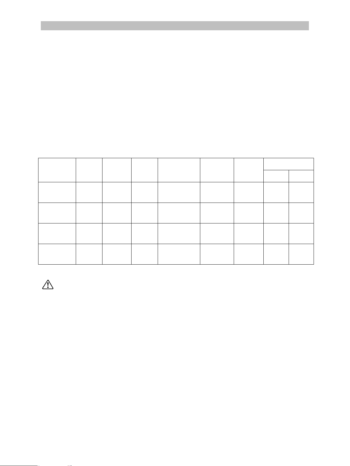
CONVERSION OF GAS
Your cooker is designed to work with natural gas,
and is convertible for use with propane or butane.
The LPG conversion kit is available from your
Service Force Centre and must be fitted by a
Corgi Registered engineer.
For changing the gas type it is necessary to:
• replace the nozzles;
• adjust the minimum level (simmer);
• check the gas connection;
SPECIFICATION NOZZLES
Table no.1
(Cat : II
2H3+
)
Burner
Normal
power
(kW)
Economic
power
(kW)
By-
pass
(mm)
Natural Gas
RAPID 2.60 0.72 0.42
Butane
Propane
RAPID
(fish)
SEMIRAPID
2.60 0.72 0.42
2.00 0.43 0.32
Natural Gas
Butane
Propane
Natural Gas
Butane
Propane
Natural Gas
AUXILIARY 1 . 0 0 0 . 35 0 . 29
Butane
Propane
Fit the label supplied with the appliance
(in the nozzles bag) corresponding to the gas
type utilised, onto the rating plate.
Gas Type
Pressure
(mbar)
20 mbar
28-30mbar
37mbar
20 mbar
28-30mbar
37mbar
20 mbar
28-30mbar
37mbar
20 mbar
28-30mbar
37mbar
Nozzle
diameter
(mm)
1.12
0,86
0,86
1.12
0,86
0,86
0.96
0,71
0,71
0.70
0,50
0,50
Cons
m3/h g/h
0.248
188,8
0.248
188,8
0.191
145,2
0.093
72,6
25
Page 26
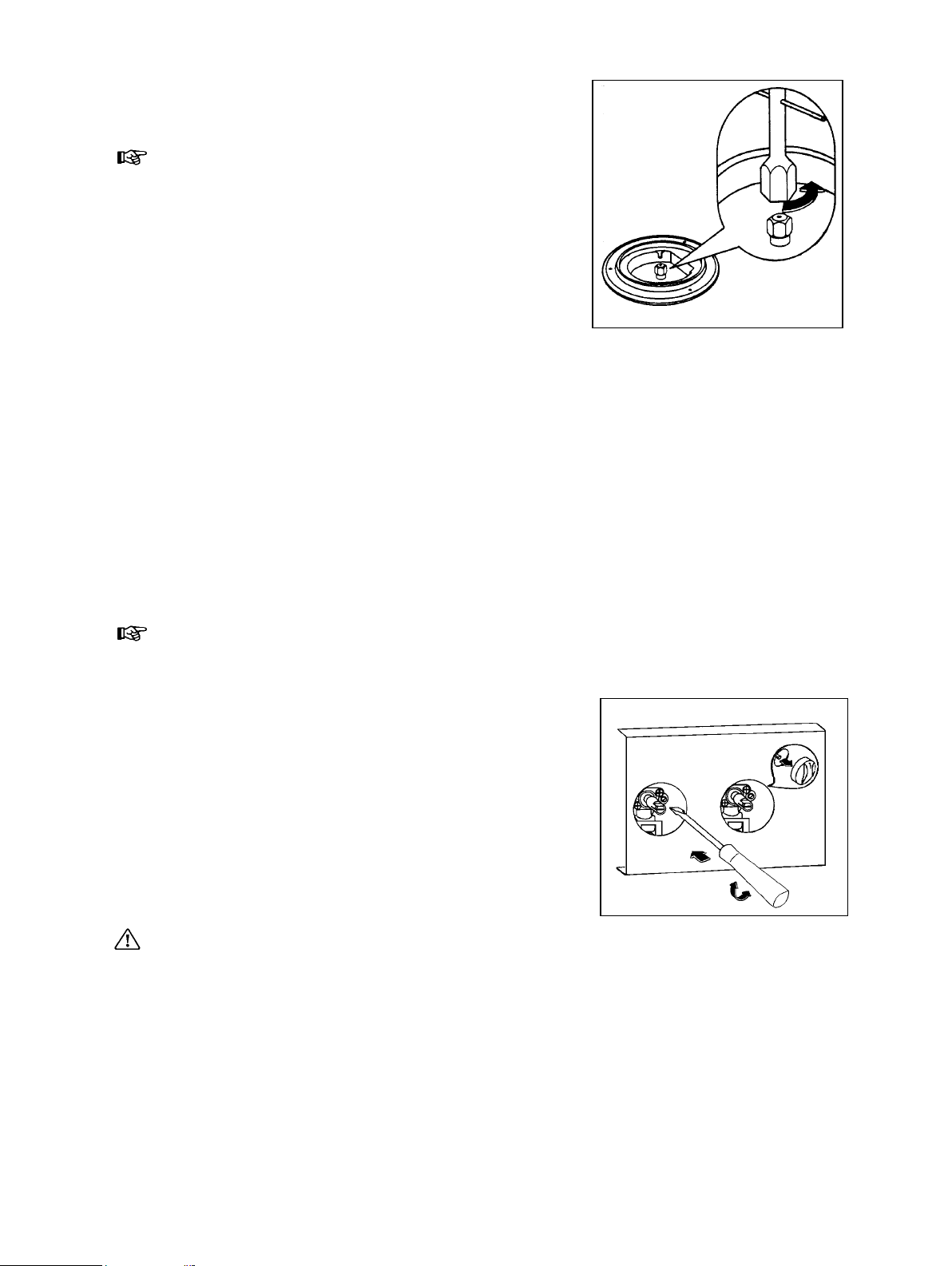
Replace the nozzles of the hob burners
Every appliance has spare nozzles for every
type of gas. The whole length of every nozzle is
marked in millimetres on the nozzle.
Hob burners
• Remove the pan support;
• Remove the caps and the burner crowns;
• Using a No 7 socket spanner unscrew the
nozzles and replace them with those required
for the type of gas in use (see table no. 1).
• Reassemble the parts following the same
procedure in reverse.
These burners do not need any primary air
regulation.
Adjustment of minimum level for the hob
burners
The burner is correctly adjusted when the flame
is stable silent and goes out without any noise.
When changing the type of gas check that the
minimum level is correct. The air admission is
correct when the flame is about 4 mm in length.
The top burners do not need adjustment of
primary air.
Check that, turning the knob quickly from the
maximum position to the minimum one, the flame
does not go out.
fig. 29
Hob burners
To adjust the minimum level:
• Light the burner
• Turn the knob to the position of the minimum
flame;
• Remove the knob;
• Unscrew or screw the by-pass screw (on the
right above of tap shaft) until a regular small
flame is reached.
• For LPG screw completely the by-pass screw.
• Reassemble the parts following the same
procedure in reverse.
Check that, when turning the knob quickly from
the maximum position to the minimum one, the
flame does not go out.
AFTER COMPLETION OF ANY REPAIRS,
ADJUSTMENTS OR CONVERSION THE
STATUTORY SAFETY TESTS MUST BE CARRIED
OUT.
fig. 30
26
Page 27

.
 Loading...