

Page 1

SERVICE MANUAL
COOKERS
© Electrolux Distriparts
Muggenhofer Straße 135
D-90429 Nürnberg
Germany
Fax +49 (0)91 1 323 1022
DGS-TDS-N
Edition:
02.06
Built-in hobs
Induction
„TEIS“
Publ.-Nr.:
599 525 284
685
EN
Page 2

Inhaltsverzeichnis
1. ESD=electrostatic discharge ............................................................................ 3
2. Software specifications, Functions ...................................................................4
2.1 Sample illustration: Induction hob......................................................................4
2.2 Control panel .....................................................................................................4
2.3 Symbol,display and keys explanation ................................................................5
2.3.1 Touch control sensor fields ...............................................................................5
2.3.2 Displays ............................................................................................................5
3. Functions of appliance ......................................................................................6
3.1 Basic functions/Child safety/Power-function.....................................................6
3.2 Safety cutoff ......................................................................................................7
4. Functional parts - Component data, installation situation, .................................8
dismantling ........................................................................................................8
4.1 General view......................................................................................................8
4.2 Contact switch and input electronics (UI)..........................................................9
4.3 Induction coil....................................................................................................10
4.4 The induction module ......................................................................................11
5. Alarm Symptoms ............................................................................................ 12
5.1 Appliance not functioning at all, cannot be switched on ..................................12
5.2 Individual cooking zones do not work (partially) or work incorrectly or
cannot be used................................................................................................13
5.3 Alarm message „E“ .........................................................................................14
5.4 Other Alarmsymptoms .................................................................................... 15
5.5 Connection guideline .......................................................................................16
5.6 Display ............................................................................................................17
5.7 Inductions module test ....................................................................................17
5.8 Pot identification information ...........................................................................18
5.9 Touch Control Cooking Hobs Information........................................................19
5.10 Demo mode / Self test (Service mode) / Alarm Menu.....................................20
6. Wiring diagrams..............................................................................................21
6.1 Example-slotted plan.......................................................................................21
6.2 Example-circuit diagram .................................................................................22
DGS-TDS-N 02.06 U. H. / A. B. © Electrolux 599 525 284 EN
- 2 -
Page 3

1. ESD=electrostatic discharge
As the single electronic interfaces are not protected internally against statical electricity and are
partially open, you must pay attention to that, in case of a repair, there will be a potential
compensation via the housing of the appliance (touch it) in order to neutralize a possible
charging and to prevent a damaging of the affected electronic interface.
You also have to be careful with those electronics delivered as spare parts, which have to be put
out of the ESD protective package only after a potential compensation (discharge of possible
statical electricity).
If a potential compensation with an existing static electricity is not executed, it does not mean
that the electronic is demaged directly. Consequential damages may result due to the damaging
of internal structures which arise only in case of load through temperature and current.
Endangered are all assembly groups which are provided with control entries, wire paths lying
open and free-accessible processors.
DGS-TDS-N 02.06 U. H. / A. B. © Electrolux 599 525 284 EN
- 3 -
Page 4
2. Software specifications, Functions
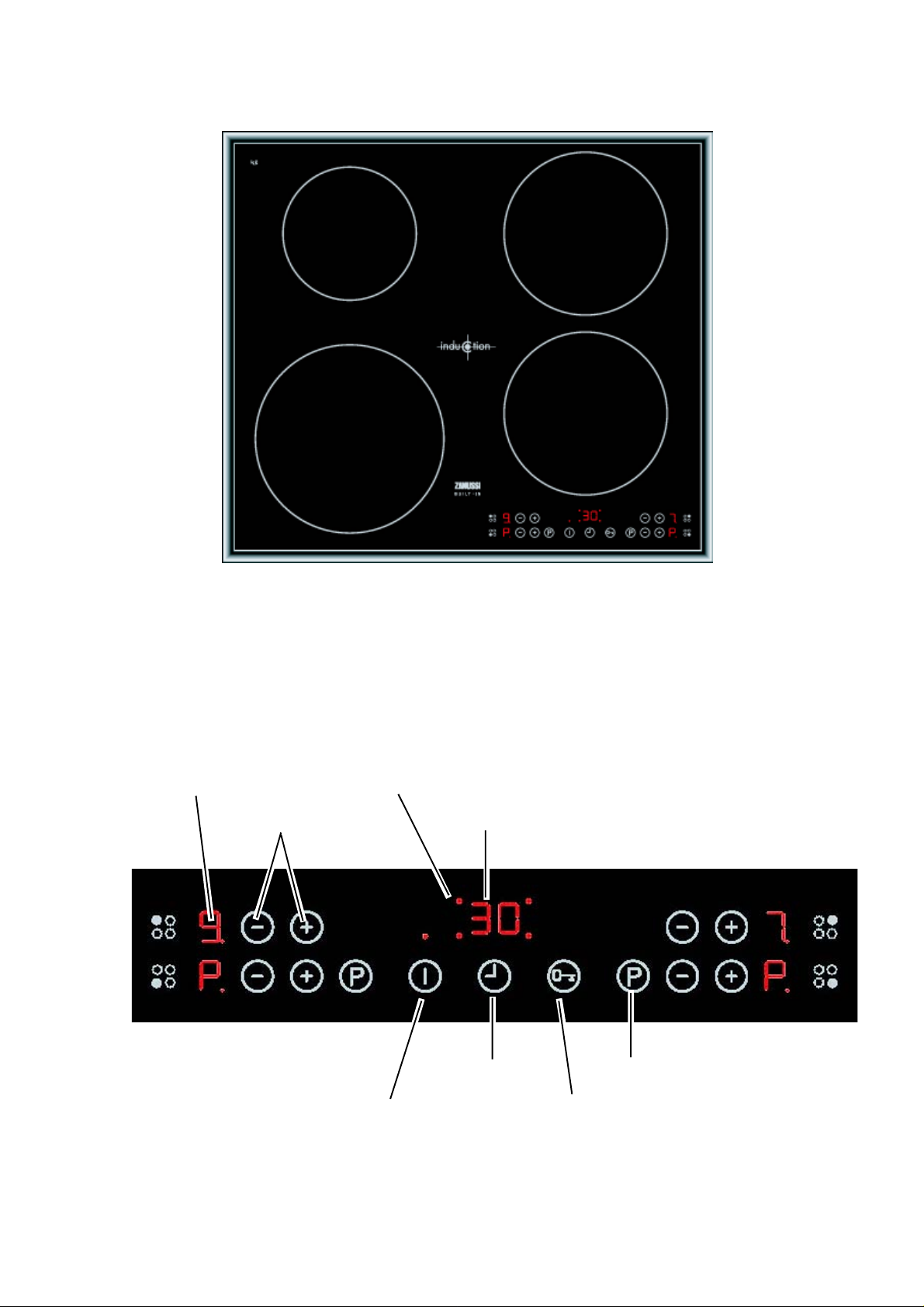
2.1 Sample illustration: Induction hob
2.2 Control panel
The symbol of the Touch control sensor field depend on the various brands, however their
functions are the same.
Display
Cooking level selection Timer Display
Cooking Zone displays, Timer Function
Timer
On/Off with control lamp
DGS-TDS-N 02.06 U. H. / A. B. © Electrolux 599 525 284 EN
- 4 -
Power function
Interlock
Page 5
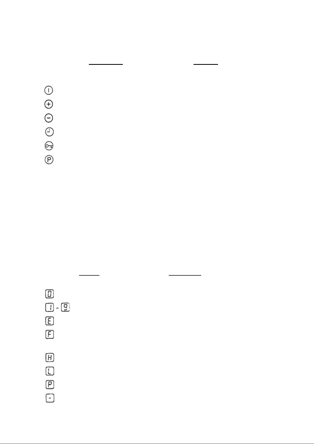
2.3 Symbol,display and keys explanation
2.3.1 Touch control sensor fields
Sensor field Function
On/Off Appliance On and Off connection
increase settings Increase cooking level/time
reduce settings Reduce cooking level/time
Timer Timer choice
Interlock Control panel lock/unlock
Power Power function Switch on/off
2.3.2 Displays
Display Description
Cooking area is switched off
Cooking levels Cooking levels are set
Fault Function failure occurs
Pot detection Cooking tablewear is unsuitable or too
small and/or it is not put on.
Residual heat Cooking area is still warm
Child safety function Interlock/Child safety is on
Power Power-function is switched off
Safety cutoff Safety cutoff is active
DGS-TDS-N 02.06 U. H. / A. B. © Electrolux 599 525 284 EN
- 5 -
Page 6
3. Functions of appliance
e
e
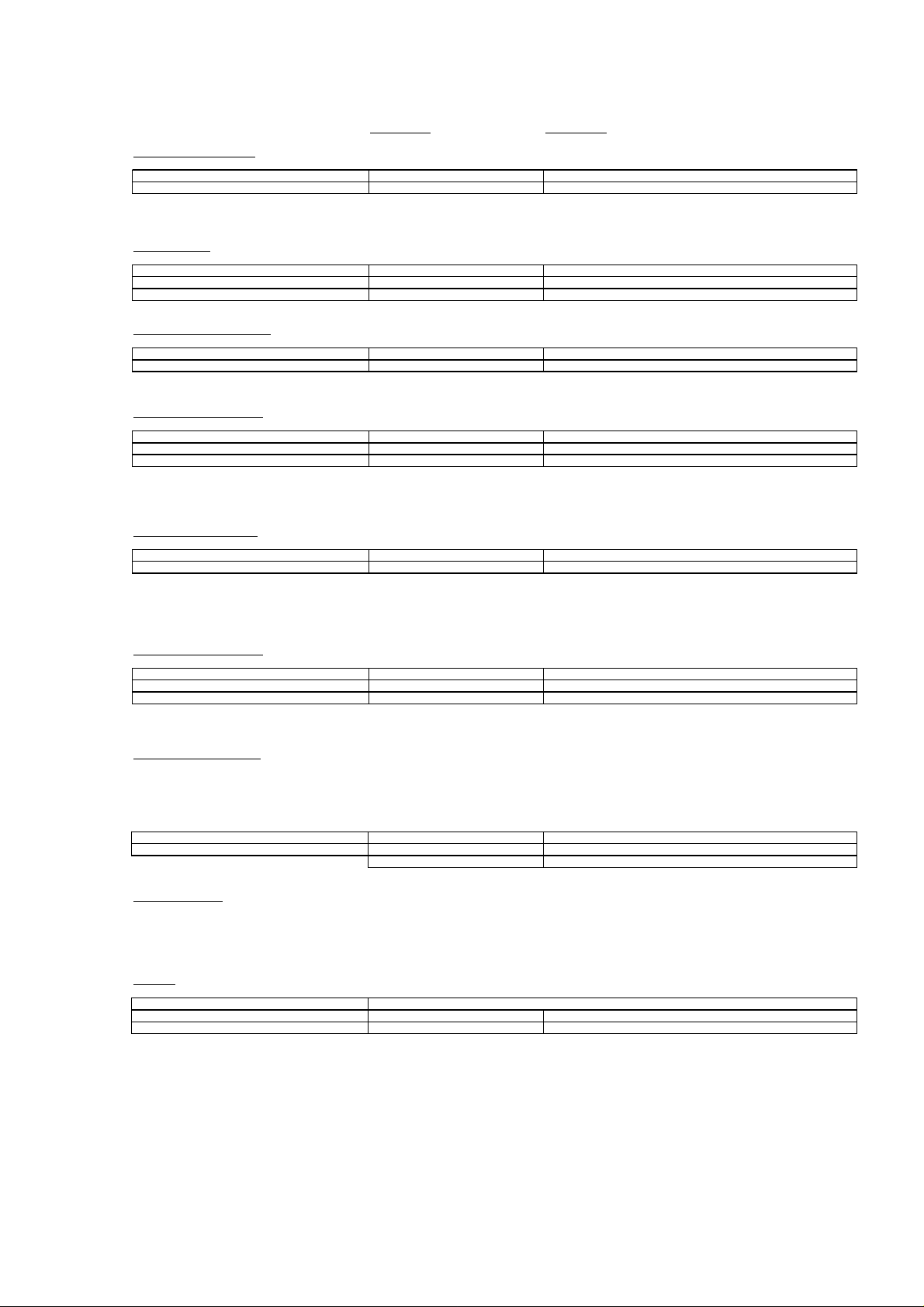
3.1 Basic functions/Child safety/Power-function
Control panel Display/signal
Switch on/off the appl i a nce
Swit ch on ( I ) Touch for 2 sec onds "0"/"H", Control la m p l i ghts up
Swit ch off ( I ) Touch for 1 sec ond "H"/none, Control lamp turns off
After s wi tching on, a cook i n g l evel or a function has t o b e set wit h in 10 seconds ,
otherwise the appli ance switches off autom a ticall y.
Set cooking level
Boos t ( + ) Touch "1" t o "9"/"P"
Minim ise ( - ) Touch "9" t o " 0 "
Swit ch off Touch ( + ) and ( - ) simultaneously "0"
Locked/unlocked control panel
Swit ch on Touch (loc k) "L" (for 3 s econds)
Switch off Touch (lock) Pre-set cooking level
When switc hi ng off the app l i ance, the lock wi l l switc h off autom atical l y.
Switch on the chil dproof lock
Step 1 ( I ) Switch on the appli a nce "0"
Step 2 Touch (loc k) until the signa l s oun ds Acoustic signal
Step 3 ( + ) Touch "L"
Appli ance swiches off. The chi l dproof lo ck is switc he d on.
Override the chi l dproof lock
Step 1 ( I ) Switch on the appli a nce "L"
Step 2 Touch ( + ) and ( - ) simultaneously "0"/Aco ustic signal
Appli ance can be us ed regularly t ill the next deactivation of the appl i an c e.
The childproof l oc k can t h erewi t h be switc he d off for an is ol a t ed cookin g act;
afterwards i t remains active.
Switch off the childproof lock
Step 1 ( I ) Switch on the apparat "L"
Step 2 Touch (loc k) until the signa l s oun ds Acoustic signal
Step 3 ( - ) Touch
Appli ance swit ches off. The ch il dpro of lo c k is switc he d off.
Switch on/off power function
The power function ( P ) provides addit i onal capac i t y for the leading induct ion cook i ng zone, e. g. to bring water to boil qui ckly.
The power function wi ll be activated at the cooki ng z o ne, u front a nd t o the left, i n 8 minutes, and at th
After this t he i nd uction, the cooking zo ne switc hes automa ticall y back to cook i ng l e vel 9. If the po wer function s tops,
the c oo king zones change back aut om atical l y to the pre-set c oo king level.
Swit ch on ( P ) Touch "P"
Swit ch off ( P ) Touch "P"
Powe r Managem ent
The cooki n g zones have a maxi m al capaci ty. If t hi s service t ype exc eeds by s wi tching on t he po wer function, the power managem en t
reduces the c ooking levels t o a not he r cooking zone. The dis pl a y of t h i s cook i ng zone changes betwe
poss ible cooking level for one minut e. Afterwards the ac t ua l cooking l evel wil l be i ndi cated.
Example:
Cooking zone most recently switched on Other cooking zones
Set cooki ng l evel Set cooking level Displ ay/ac t ual cooki ng l evel
"P" 9 6 al ternately with 9/6
If the power funct i on stops , the cook i n g zones ch ange bac aut omatic a l l y to the pre-set cooking levels.
( - ) Touch "9"
cook i ng zone, up front and to the right , in 5 min ut es.
the pre-s et and max im u m
DGS-TDS-N 02.06 U. H. / A. B. © Electrolux 599 525 284 EN
- 6 -
Page 7

3.2 Safety cutoff
Cooking field: - If you do not set a cooking level in a cook zone within approx. 10 seconds
after switching on of the cook field, the cook field switches off
automatically.
- If one or more sensor fields are covered longer than 10 seconds, e.g. by
a pot placed on it, a signal sounds and the cook field switches off
automatically.
- If all cook zones are switched off, the cook field switches off
automatically approximately 10 seconds later.
Control panel: Humidity (e.g. a wet cloth) or over-cooking liquid on the control panel switches all
cook zones off immediately.
Induction cooking zones: - During overheating (e.g. an empty-cooked pot) the cook zone switches
off automatically. „- “is displayed. Before renewed use the cook zone
must be set to „0 “and be cooled down.
- If suitable table-ware is used, „F“ flashes in the display and after 10
minutes the display of the cook zone switches off.
- If one of the cook zones is not switched off after a certain time or if the
cook stage is not changed, the appropriate cook zone switches off
automatically.
cooking level The cooking zones are disconnected with:
1-2 6 Hours
3-4 5 Hours
5 4 Hours
6-9 1,5 Hours
DGS-TDS-N 02.06 U. H. / A. B. © Electrolux 599 525 284 EN
- 7 -
Page 8

4. Functional parts - Component data, installation situation,
dismantling
4.1 General view
Contact switch and
holding frame UI
Input electronic (UI)
Insulation
Induction coil
Module of induction
Insulation
Sensor plate aluminium
Sensor
Support spring
DGS-TDS-N 02.06 U. H. / A. B. © Electrolux 599 525 284 EN
- 8 -
Page 9

4.2 Contact switch and input electronics (UI)
The contact switch is glued directly on the glass ceramic and over a foil conductor connected
with input electronics. The UI is fixed in a plastic framework, which is also glued directly onto on
the glass ceramic.
Fig. 1 Fig. 2
The trough framework is screwed onto the trough bath with star Torx TX20 screws. Before the
glass ceramic can be removed after the complete loosening of the star screws, it must be lightly
raised at the front, so that both 3-pole connection cable input electronics/ induction module can
be taken off (fig. 1).
Fig. 3
Input electronics are configured and provided with a standard software. After extracting from the
holding frame and taking the foil conductor off input electronics can be removed.
DGS-TDS-N 02.06 U. H. / A. B. © Electrolux 599 525 284 EN
- 9 -
Page 10

4.3 Induction coil
The spare part induction coil consists of the coil body, the white insulation and a coil holder.
Fig. 1
Fig. 2 Fig. 3
The induction coils are held with springs, which must be locked into the induction module carrier
(fig. 1). The nominal reduction rates in the trough (fig. 3) serve as position indicators.
Performance table
Chosen % of the m aximum Cooking z one Cooking zone Cooki ng zone
cooking level performance 140mm 180mm 210m m
13.0%425466
2 5.5% 77 99 121
3 10.5% 147 189 231
4 15.5% 217 279 341
5 21.0% 294 378 462
6 31.0% 434 558 682
7 45.0% 630 810 990
8 64.0% 896 1152 1408
9 100.0% 1400 1800 2200
P 2800 2800
DGS-TDS-N 02.06 U. H. / A. B. © Electrolux 599 525 284 EN
- 10 -
Page 11

4.4 The induction module
With this series the induction modules are implemented as double modules, i.e. an induction
trough with four induction cook places has 2 induction modules (fig. 1). The induction module is
provided with a standard software and does not have not to be programmed.
Fig. 1
Fig. 2 Fig. 3
The induction module of the trough is held with four sheet metal noses (fig. 2), in each case two
above and below, which are led through the induction module carrier and interlocked afterwards.
Technical data
Main voltage: 230V
Rated frequency: 50/60Hz
Max. output: 3.6kW
Output per cooking area max.: 2.8kW
Total output: 3.6kW
Ambient temperature max.: T 85
DGS-TDS-N 02.06 U. H. / A. B. © Electrolux 599 525 284 EN
- 11 -
Page 12

5. Alarm Symptoms
5.1 Appliance not functioning at all, cannot be switched on
Alarm
Symptom
House fuse
triggered
Cooking
field cannot
be switched
on.
Connector of the cable to
Fuse strip conductor burnt
Touch control defect. If 5VDC exist and power
Cooking
Hob
Display
None
No mains voltage or
Possible Alarm
Cause
Incorrect connection at
the power connection
terminal.
Final induction phase
defect.
incorrect connection (1
phase missing ->no
control voltage; N not
connected to terminal 4
and 5 not connected)
the Touch Control
/Display not inserted.
out and/or final induction
phase defect
Alarm Remedying
Test the pin assignment and
230VAC between N , Lines and
earth on the supply line.
See chapter Testing Power
Component
Test the pin assignment and
230VAC , Neutral, Line(s) and
earth. Both of the "N“s should be
connected to wall terminals.
Test connector at the filter and
Touch Control. Reapply the mains
voltage.
See Chapter Testing Power
Component
component already replaced:
replace the UI. Ensure that the
Touch pcb is well glued to the
glass, and that the connection wire
is well inserted.
DGS-TDS-N 02.06 U. H. / A. B. © Electrolux 599 525 284 EN
- 12 -
Page 13

5.2 Individual cooking zones do not work (partially) or work incorrectly or cannot be used
Alarm Symptom Cooking
Hob
Display
Pan does not
heat up.
No power on all
hobs
Individual buttons
cannot be used
or cannot always
be used.
Cooking hob
power too low or
not provided for a
longer duration.
"H" in display
when cooking
hob and oven
cold and
switched off.
Normal cooking
phase
Flashing
"F“
Normal cooking
phase
Touch Control defect. 1) See Chapter 5. Touch
Normal cooking
phase
"H“
Possible Alarm
Cause
Pan in the border area of the pan
detection and only works with low
power
Pan not detected. Check whether t he pots or
Coil not correctly connected. Check whether the coil lines
Distance between coil and glass
ceramic too large.
Demo mode activat ed. See Chapter demo mode
Incorrectly installed, exhaust not
possible to the front.
Unsuitable pots (bottom bent) See Chapter Pot De tection
Induction coi l i s not applied to the glass
ceramic
Fan does not start. 1) When setting a cooking
Temperature sensor defect. Replace corresponding coil
Alarm Remedyi ng
Use different pot or this pot
on a smaller hob. See
Chapter Pot Detection
Information
pans are suita ble for
induction. See Pot Detection
Information
are connected and the torque
has been adhered to.
Check whether the coil is
applied to the glass ceramic
and whether the glass was
pushed was pushe d down
when screwing in position.
Control Cooking Hobs
Information.
2) Should this not help,
replace Touch Con trol.
See chapter installation
situation.
Information
Check whether the glass
ceramic was pushed down
when being screwed in
position and the coil has
been correctly posit ion ed.
phase >0, the fan ru ns at a
slow speed. If not, check the
fan for foreign bodies,
remove these where
appropriate.
2) If necessary, replace fan.
3) Should this not succeed,
replace power component.
with temperat ure sensor.
Also see Instructions "E4“.
DGS-TDS-N 02.06 U. H. / A. B. © Electrolux 599 525 284 EN
- 13 -
Page 14

5.3 Alarm message „E“
When the appliance is switched on, „E“ / „xx“ Alarm Number is displayed in the timer display.
The affected zones are subsequently displayed with an „E“ in the cooking phase display and are
thereby disabed. The other zones can still be used.
Example:
1) Error code 8 for the left board
Alarm
Symptom
Alarm display
in the Touch
Control.
"E3“ 400 VAC detected, instead
"E4“ Coil temperature sensor
"E5“ Coil temperature sensor
Display in
the Cooking
Hob Timer
"E2“ User interface temperature
Possible Alarm
Cause
too high
of 230VAC, on left or right
module or both
defect, not correctly
connected, or broken,
display in the corresponding
zone.
defect, short, display in the
corresponding zone.
Alarm Remedying
Temperature too high due to
installation, or UI defect.
1) verify power lines connection,
on the wall
2) Should alarm still be
displayed, verify internal
connection in the hob,
3) Should alarm still be
displayed, See Chapter Testing
Power Component
1) Inspecting the contacts on
the power board. Is the
connector inserted?
2) The resistance at room
temperature (25°C) amounts to
100 kOhm. If not in this range,
replace affected temperature
sensor.
3) Should above not succeed,
replace power component
concerned.
1) Inspecting the contacts on
the power board.
2) The resistance at room
temperature (25°C) amounts to
100 kOhm.If not in this range,
replace affected temperature
sensor.
3) Should above not succeed,
replace power component
concerned.
DGS-TDS-N 02.06 U. H. / A. B. © Electrolux 599 525 284 EN
- 14 -
Page 15

Alarm
Symptom
"E6“ Communication defect
"E7“ “7.” Alarm Temperature
"E8“ Communication
"E9“ Communication defect
Display in
the
Cooking
Hob Timer
Possible Alarm
Cause
inside power board
sensor heat sink power
component E7 open
E7. short
interference between
power and User
interface.
inside user interface
Alarm Remedying
Replace identified power board.
E7, verify connector, if not OK,
Replace affected power component.
E7. Replace affected power component.
1) if left, Verify the power wiring in the
wall. If OK, Reinsert connector of UI,
Or replace cable. If not OK go to 3)
2) if Right, Verify middle connection of
cable of UI, replace cable, if not OK go to
3),
3) take cable of left power board and
connect to right power board, with a test
cable longer connect UI right to power
board left. A) same as before change
User interface, “E6” crossed change the
power board identified.
Replace User interface.
5.4 Other Alarmsymptoms
Alarm Symptom Display Possible
Buzzer defect Touch
Individual display
elements do not
illuminate or do not
do so continuously.
Pots cause noises Unsuitable
Normal
Alarm Remedying
Alarm
Cause
Replace User interface.
control
defect.
Defective
display
elements
pots.
sound level
Replace User interface.
See Chapter Pot Detection Information.
Interference noises result from the high
working frequency of the induction. This can
vary from pan to pan. When measured in
operation pursuant to EN60335 §11-3
pursuant to EN60704 with 4 pots <47dBA. A
pot with boiling water has approx. 60-62dBA.
DGS-TDS-N 02.06 U. H. / A. B. © Electrolux 599 525 284 EN
- 15 -
Page 16

5.5 Connection guideline
Power cords inside the hob
DGS-TDS-N 02.06 U. H. / A. B. © Electrolux 599 525 284 EN
- 16 -
Page 17

5.6 Display
For details, refer to Instruction Manual - Cool top platform
Symbol Comment
„.“ Intermediate cooking levels
„-“ Induction – zone switched off because of over temperature at the coil sensor
(empty pot)
„A“ Fast heating up function („Ankochstoss“)
„E“ On alarm display see error!
„F“ Pot detection – no pot detected
„H“ Residual heat indication
„L“ Lock – Function or key lock
„P“ Power (booster) function for induction
5.7 Inductions module test
1. When alarm messages and disabled zones exist (“E“ in cooking phase display), please
make a note of the power component which is affected.
2. Check power lines and connection to user interface is connected,
3. If IGBT has become shorted, this normally means that the IGBT housing is damaged.
Replace power component.
4. Measure resistance at the IGBTs
Pin1-Pin2 or Pin2-Pin3 >50kOhm f Okay
<50Ohm f power component defect & replace
Only replace the affected power component.
„IGBT“
DGS-TDS-N 02.06 U. H. / A. B. © Electrolux 599 525 284 EN
Pin 1 2 3
- 17 -
Page 18

5.8 Pot identification information
Suitable pot materials:
- Steel enamel
- Stainless steel (with magnet. bottom)
- Aluminium (with magnet. bottom)
- Cast iron
Unsuitable materials:
- Aluminium (à too much power)
- Copper
- Stainless steel (not magnetic)
- Glass
- Ceramic
The pot detection is designed for the following diameters:
Nominal burner ∅ [mm] Minimum pot bottom ∅
instruction manual [mm]
145 125 100
180 145 120
210 180 140
With regard to Ind. G4, the same diameter is stipulated in the
instruction manuals as for the previous model. However, the
real diameter which still functions is much smaller.
The performance for different pots can very by as much as +/
- 10-15%.
- As reference pots, we recommend enamelled steel pots
(e.g. Silit).
Minimum pot bottom ∅
adjusted with steel plate
[mm]
- 2-3 mm thick round steel plates in various diameters are
very suitable for testing the pot detection function.
- Sandwich bottoms can cause very unpleasant noises if
they are not correctly pressed. The same is the case
with regard to handles which are a little loose.
DGS-TDS-N 02.06 U. H. / A. B. © Electrolux 599 525 284 EN
- 18 -
Page 19

5.9 Touch Control Cooking Hobs Information
- The Touch Control works on the basis of the capacitive principle, an amortizing mass is
detected, the signal modified is treated with some rules and validated as an action.
- If the user interface is not applied to the glass ceramic, the signal for the button evaluation
is much smaller and the buttons can no longer be used, i.e. always ensure that the plastic
supports are always intact.
- Should the appliance switch itself off without the glass ceramic having been touched, this
is due to a button being activated. Either external water or material on the glass.
Instructions on the operation / possible operation errors if the buttons do not function:
- Please do not approach slowly, especially not from the side, it is better to approach the
button faster. A signal change is above all evaluated.
- Applying excessive pressure to the cooking hob will not make a difference. It is better to
release it for 5 sec. and then press the button again.
- If the adjustment of the cooking stage/timer does not continue after the button has been
released, this is due to the fact that the Touch Control receives a „Button Pressed“ signal
even from a distance of some mm.
DGS-TDS-N 02.06 U. H. / A. B. © Electrolux 599 525 284 EN
- 19 -
Page 20

5.10 Demo mode / Self test (Service mode) / Alarm Menu
To enter the Demo mode / service mode / factory test menu , the following sequence of buttons
must be pressed:
1. Hob is off. Press main switch continuously until display is going off (without beep).
2. Press the „+“ and „ -“ buttons (2a) of both front zones together (all 4 keys togehter ) for
about 3 seconds (-> short beep).
3. Press the timer selection key (-> again short beep).
4. The display (C) shows a “d” for demo mode. If you press the timer select key again you
switch to “S” for service mode, another presee gets you to “E” the alarm menu!
5. By pressing the button “+” of a cooking zone you activate the menu.
6. By pressing the button “-“ of a cooking zone you deactivate the menu.
Demo Mode:
If demo mode is activated the display with the „d“ shows additionally a dot. After selecting the
demo mode, the electronic goes to off. Now it can be used like usual but only without heater
activation. The deactivation of the demo mode is done in the same procedure as activating. After
deactivating the demo mode the electronic must go off. Now the hob can be used in normal
mode.
Service Mode “S”
Routine:
1. Show user interface SW version
2. Show control SW version
3. Show power SW version
4. 400V detection test: “400U” blink on displays until 400V is not applied. When 400V is
detected, the buzzer ring and “OU” is shown on display until 230V is not applied.
5. Test all LEDs / Displays for 7 sec; during this time, booster is set on rear zones to test
sensors. When the time is elapsed, if the sensor are OK the test jump to the following step
otherwise “S” is shown alternatively on zones where the error occurred.
6. Zone power test: a different power level is set on each zone for 2 seconds
Alarm Mode “E”
The last 5 stored alarm codes (if >o) are displayed like an actual alarm, each for 5 sec., starting
with the oldest (read request ‘5’ Alarm code message) to the newest (read request ‘1’).
DGS-TDS-N 02.06 U. H. / A. B. © Electrolux 599 525 284 EN
- 20 -
Page 21

6. Wiring diagrams
6.1 Example-slotted plan
DGS-TDS-N 02.06 U. H. / A. B. © Electrolux 599 525 284 EN
- 21 -
Page 22

6.2 Example-circuit diagram
DGS-TDS-N 02.06 U. H. / A. B. © Electrolux 599 525 284 EN
- 22 -
 Loading...