

Page 1

Instantaneous
IH 18 electronic basic
Water Heater
IH 21 electronic basic
IH 24 electronic basic
Instructions for installation and use
Page 2

Contents Page
Important instructions for the user 3
General 3
Operating the appliance 3
Temperature preselection 3
Hot water flowrate 4
Care and maintenance of the appliance 4
Important instructions for the installer 5
General 5
Appliance constitution 5
Technical data 6
Appliance function 7
Safety temperature limiter 7
Installing the appliance 8
Dimensioned diagram 8
Appliance installation 9
Hood dismounting 9
Wall mounting 9
Water connection 10
Concealed installation 10
Installation versions 11
Cleaning the strainer insert 12
Flowrate limiter 12
Electrical connection 13
Mains connection 13/14
Circuit diagram 14
Temperature selector range limitation 15
Hood assembly 15
Using the appliance for the first time and checking 16
Fault-finding 17
Fault indications 18
Important for the expert 19
Customer service 20
2
Page 3
Important instructions for the user
General
- Installation and startup should only ever be performed by an approved
installer or authorised installation firm.
- Before using the appliance, please read through these instructions
carefully. The manufacturer cannot accept any liability for damage
resulting from failure to follow these instructions.
- Fittings and connecting pipes may get hot. Therefore keep children well
away.
Operating the appliance
The ELECTROLUX IH electronic instantaneous water heater heats the water
as the latter continuously flows through it. When the hot water tap is opened,
the appliance switches on at a flowrate of around 3 l/min. When the hot water
valve is closed or if the flowrate is reduced below 2.5 l/min, the appliance
switches itself off again. The appliance is suitable for household use and should
only ever be used for heating of drinking water.
One or more tapping points can be supplied with hot water.
Temperature preselection
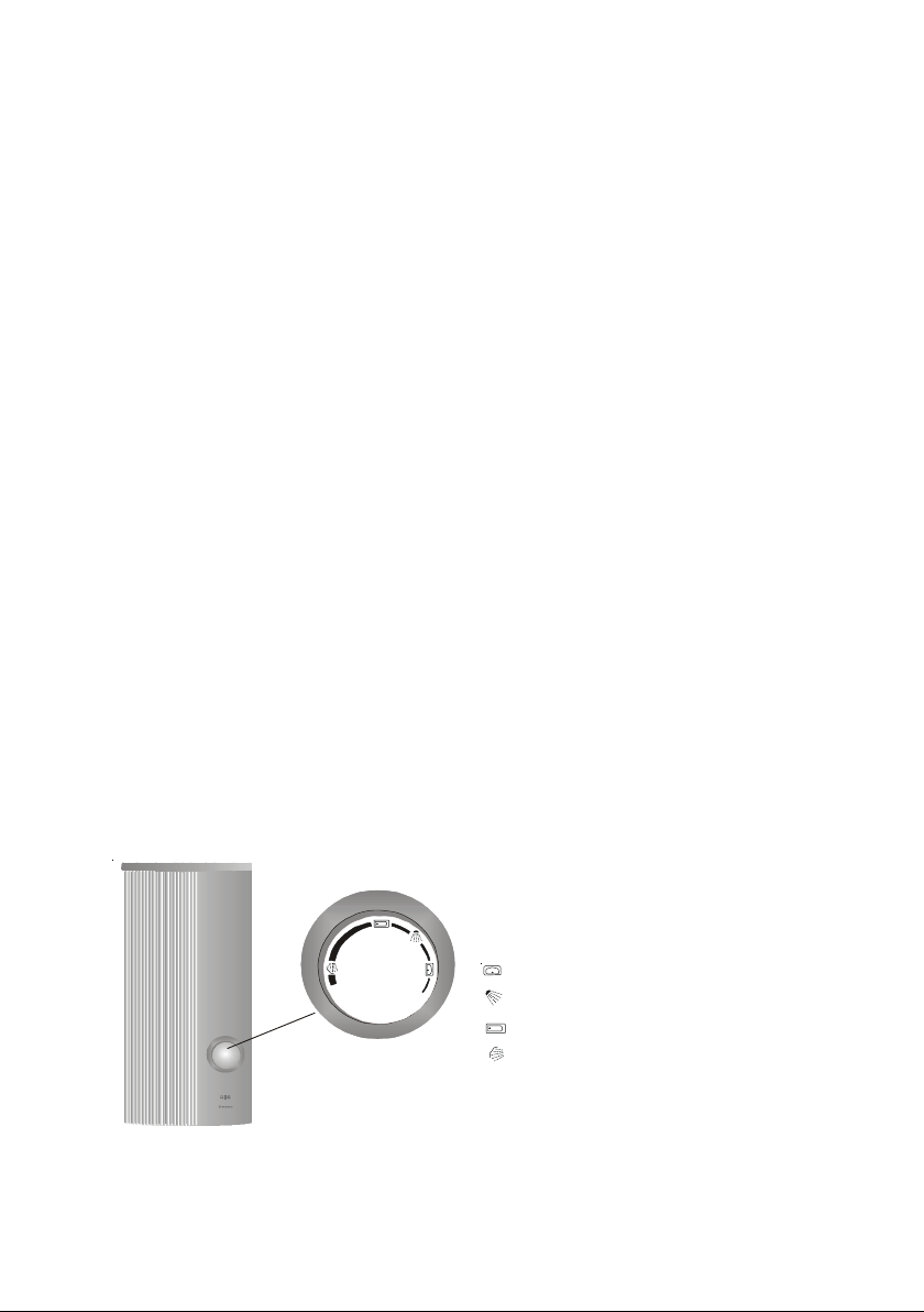
The electronic system allows continuous temperature selection in the range
from 30°C to 60°C.
Recommendation for energy-saving operation:
40°C for washbasin, shower, and bath (knob tangibly engages).
55°C for kitchen sink. If this temperature
is no longer needed, the appliance
should be reset to the 40°C energy-
saving level.
Wash basin
Shower
Bath basin
Kitchen sink
When the appliance is operated with a
thermostatic mixer tap, the temperature
setting on the instantaneous water
heater must be around 8°C higher than
on the thermostatic mixer tap.
3
Page 4

Hot water flowrate
Cold
water
tempe
rature
°C
Outlet temperature
40°C
Outlet temperature
55°C
6
10
14
18 kW
l/min
7,6
8,6
(*8)
9,9
(*8)
21 kW
l/min
8,8
10
(*9)
11,6
(*9)
24 kW
l/min
10,1
11,5
(*10)
13,2
(*10)
18 kW
l/min
5,3
5,7
6,3
21 kW
l/min
6,1
6,7
7,3
24 kW
l/min
7
7,6
8,4
(*) limited to this figure by the built-in flow limiter
Up to the appliance’s max. power limit, the instantaneous water heater
supplies the set hot water temperature regardless of the water flowrate
selected.
If the hot water temperature is not attained when the hot water valve
is fully opened, more water flows than can be heated by the
appliance power. In this case, the hot water tap must be slightly
closed.
Because of the different inlet temperatures, the hot water output varies
depending on the season.
The following outlet flowrates for bath or shower water (40°C) or washbasin/
sink water (55°C) are attained at the inlet temperatures of 6°C, 10°C,
and 14°C.
Care and maintenance of the appliance
Clean the plastic housing as necessary with a damp cloth and dilute soap
solution. Never use any abrasive, scouring, and solvent-containing detergents.
The instantaneous water heater generally needs no maintenance. Regular
inspection of the appliance by a trained engineer will ensure its operational
reliability and prolong its service life.
Scale deposits in the outlet of fittings reduce the water flowrate. The air
bubblers of the fittings or hand shower head must therefore be cleaned from
time to time.
4
Page 5
1
2
3
4
5
10
11
3a
4a
12
6
7
8
9
13
14
Important instructions for the installer
General
The instantaneous water heater is manufactured and tested in conformity with
the valid IEC specifications and DIN standards. The appliance complies with
the Appliance Safety Act. The indications given on the rating plate, the technical
connection specifications of the electricity and water companies in the
geographical area concerned, and VDE 0100 and DIN 1988 must be observed
when the appliance is being installed.
The specific resistance of the water at the installation site should not
be less than 1100
ΩΩ
Ωcm.
ΩΩ
This appliance complies with the following EC Directives:
- the ”Low-Voltage Directive” 72/23/EEC of 19.02.1973, including
Amendment Directive 93/68/EEC
- the”Electromagnetic Compatibility” Directive 89/336/EEC of
03.05.1989 including Amendment Directive 92/31/EEC
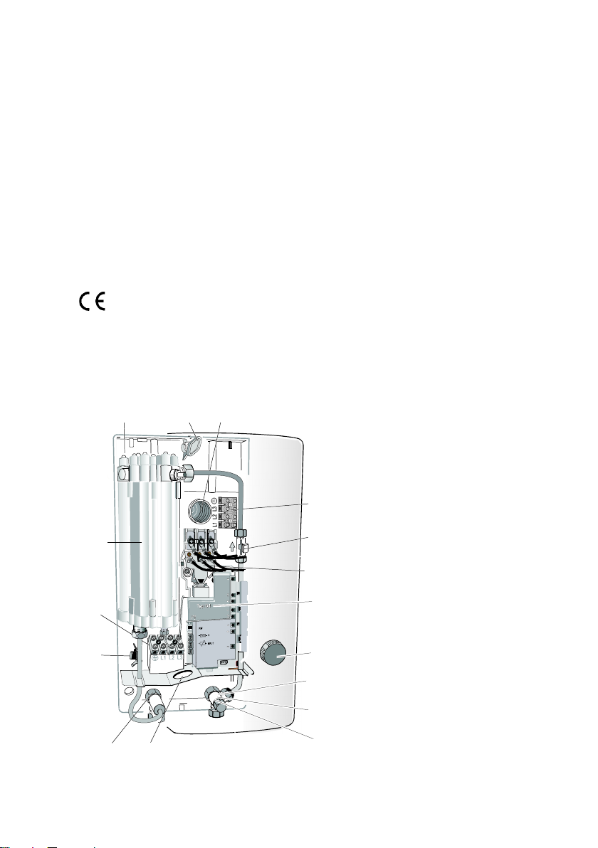
Appliance constitution
1 = Back wall
2 = Quick fastener for appliance
mounting
3 = Upper cable bushing
3a = Lower cable bushing
4 = Upper mains connection
terminal (factory-prefitted)
5 = Flowrate sensor
6 = Safety temperature and
pressure limiter
7 = Electronic module
8 = Temperature selector knob
9 = Flowrate limiter
10 =Strainer insert
11 = Cold water connection
12 =Hot water connection
13 =Thermostat
14 =Heating block
5
Page 6
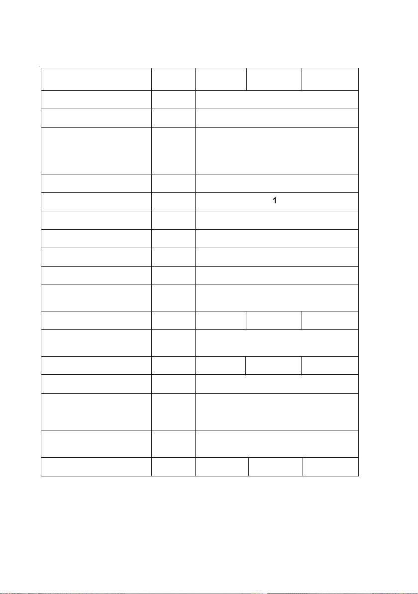
Technical data
Model
Type unvented
Nominal capacity
l
0,4
Dimensions
Width
Height
Depth
mm
226
469
99
Weight
kg
3,9
Nominal overpressure
Mpa
Protection class to VDE
I
Protection type to VDE
IP 25 (splash-water protected)
Test mark
See rating plate
Water connection
G 1/2 A
Electrical connection
3 / PE ~ 380 V
Nominal output
kW1821
24
Spec. water resistance at
15 °C
Ohm cm
> 1100
Switch-on flow pressure*)
Mpa
0,035
Switch-on flowrate
l/min
3
Mains retroactive effect
Free from any mains retroactive effect
to DIN EN 60555/VDE 0838
VDEW Approval
Maximum inlet
temperature
°C
25 °C
IH E
24 basis
IH E
21basis
IH E
18 basis
Flowrate limitation l/min 8 9 10
0,04
0,03
*) In addition to the flow pressures of the instantaneous water heater itself, consideration
must be given to the pressure losses in the household pipework.
6
Page 7
Appliance function
The fully electronically controlled ELECTROLUX IH instant water heater is a
pressurised appliance for the supply of one or more tapping points and heats
the water as the latter continuously flows through it. A flowrate sensor switches
on the heating at a flowrate of around 3 l/min and off again at around 2,5 l/min.
The microprocessor controlled electronic system automatically adapts the
heating power with regard for the inlet temperature, the temperature set on the
temperature selector knob, and the water flowrate. The user thus has hot
water available in an energy-saving system giving the exact temperature required
without any time limitation whatever.
The nominal operating pressure is 1 Mpa. If this value is exceeded, a pressure
reducing valve should be provided in the household pipework. A safety valve is
not necessary.
The bare wire resistance heating system has a high efficiency. Its low weight
and extremely low water content also make it suitable for hard, lime-containing
water qualities.
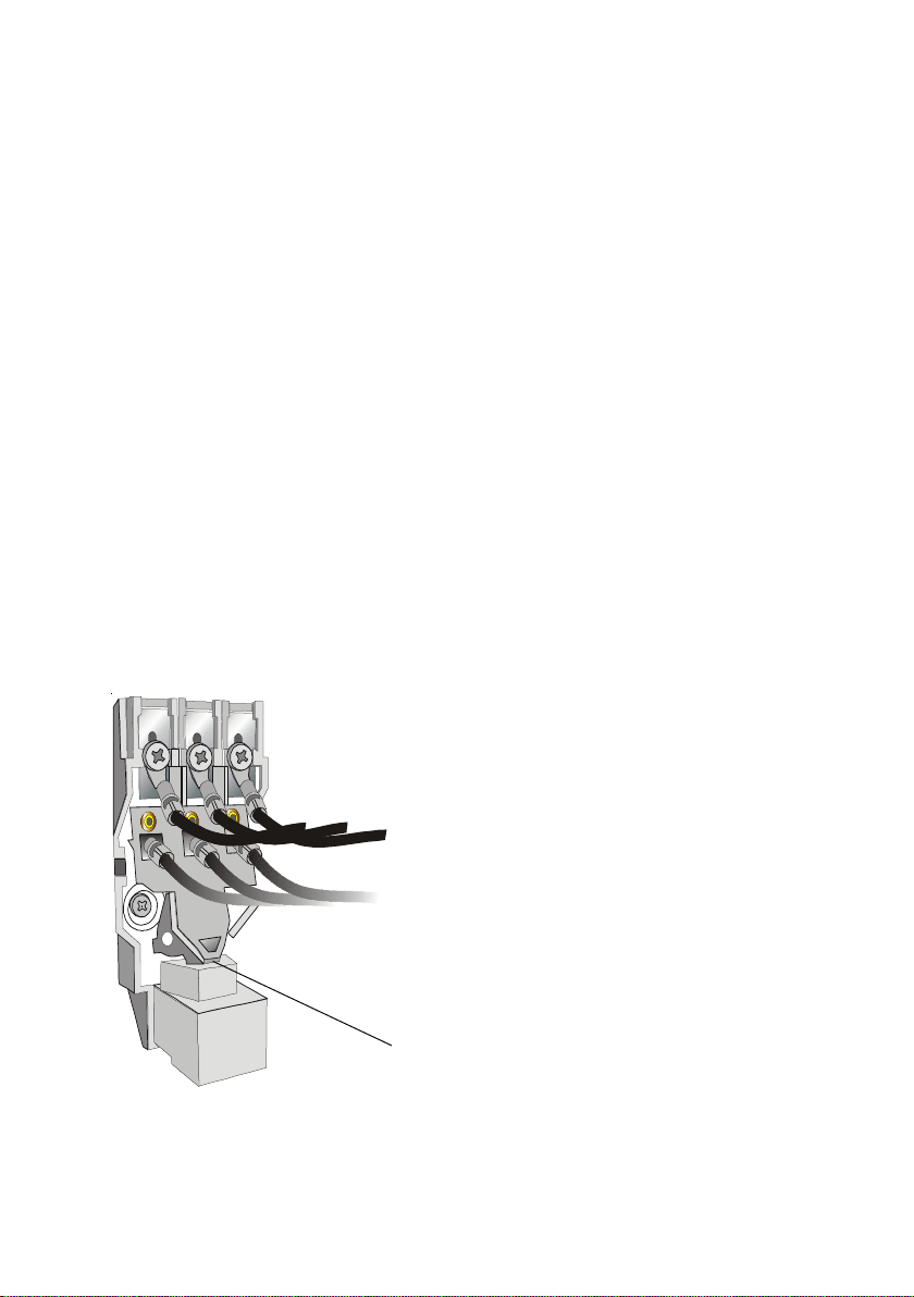
Safety temperature and pressure limiter
In the event of a fault, the inbuilt safety
temperature limiter isolates the appliance from
the mains supply on all contacts.
Before the appliance is switched back on, a
trained engineer must ascertain and eliminate
the cause of the fault (see page 17). Then
carefully press in the contact rocker with a
screwdriver until it audibly engages.
Important: Don't block up the contact rocker!
Pressurepoint
for screwdriver
Important! The safety temperature and pressure limiter should never
be adapted or modified in any way!
7
Page 8
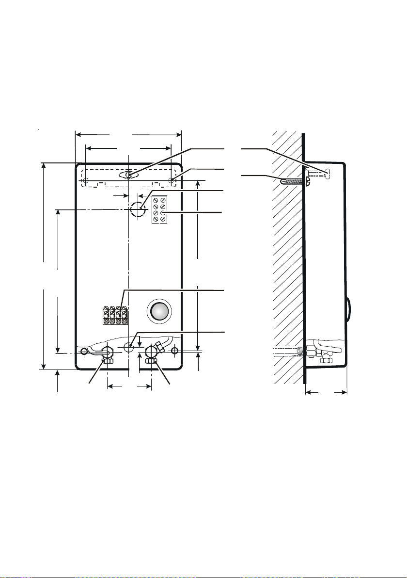
Installing the appliance
1
2
3
4
4a
3a
5
6
226
190
100
90
37,5
5
4
6
9
2
9
3
395
21
30
The appliance should only ever be installed or stored in frost-free
premises.
Dimensioned diagram
1 = Quick fastener for appliance mounting
2 = Wall mounting
3 = Upper connection terminal (factory-set)
3a = Lower connection terminal for electrical connection
4 = Upper cable bushing
4a = Lower cable bushing for electrical connection
5 = Cold water connection with strainer insert
6 = Hot water outlet
8
Page 9
Appliance installation
1
2
3
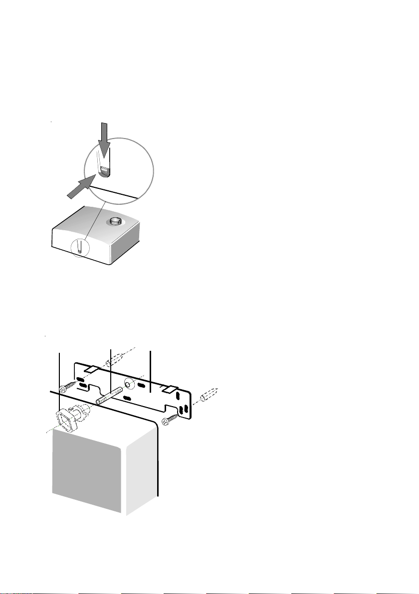
Carefully unpack and take out the enclosed pack.
Prepare the appliance for assembly.
Hood dismounting
Press in the engagement lug on the underside of
the appliance from above or from the front with a
screwdriver and take off the hood. Pull out the
connection lead of the temperature set-point
pickup on the electronic system.
The rotational range of the temperature selector
knob can be limited (see page 15).
Wall mounting
Mark out wall-plug holes with the
mounting template supplied,
insert wall-plugs, and screw on
fixing rail (1). Take out threaded
pin (2) from the enclosed pack
and screw in. Then prepare water
connections, mount appliance on
threaded pin and retaining rail,
and fix by turning the quick
fastener (3) one quarter revolution.
9
Page 10
Water connection
The water inlet temperature on the cold water connection should be
max. 25°C.
If plastic pipe systems are used as installation material, the pipe
manufacturer must expressly and unreservedly confirm the
applicability and quality of his pipes for this application.
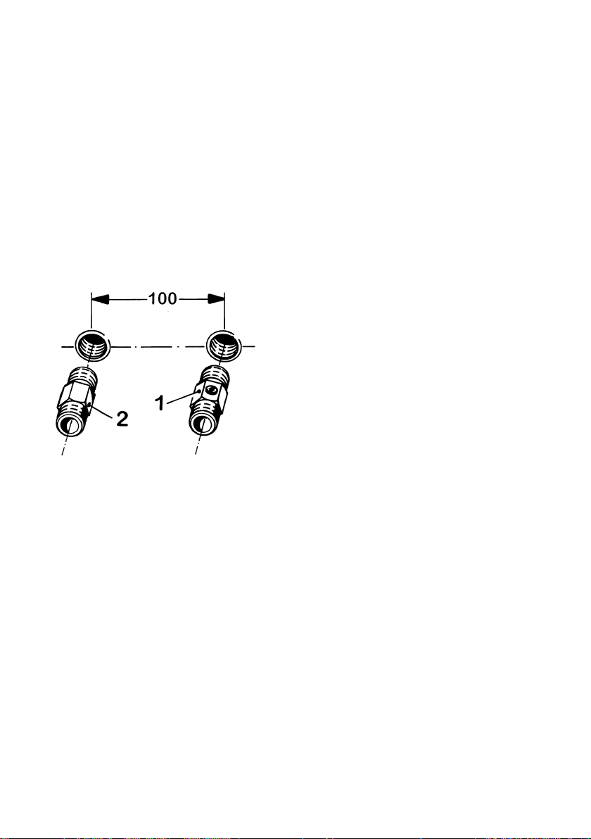
Concealed installation
Insert connector with shutoff spindle (1) in
cold water connection and double- nipple
(2) in hot water outlet using hemp packing.
The shutoff spindle must point downwards
and the screw slot aligned in the flow
direction of the water. The shutoff unit
must not be used for throttling.
The ELECTROLUX IH electronic can be operated with all pressure fittings
suitable for instantaneous water heater.
10
Page 11
Installation versions
1
2
3
4
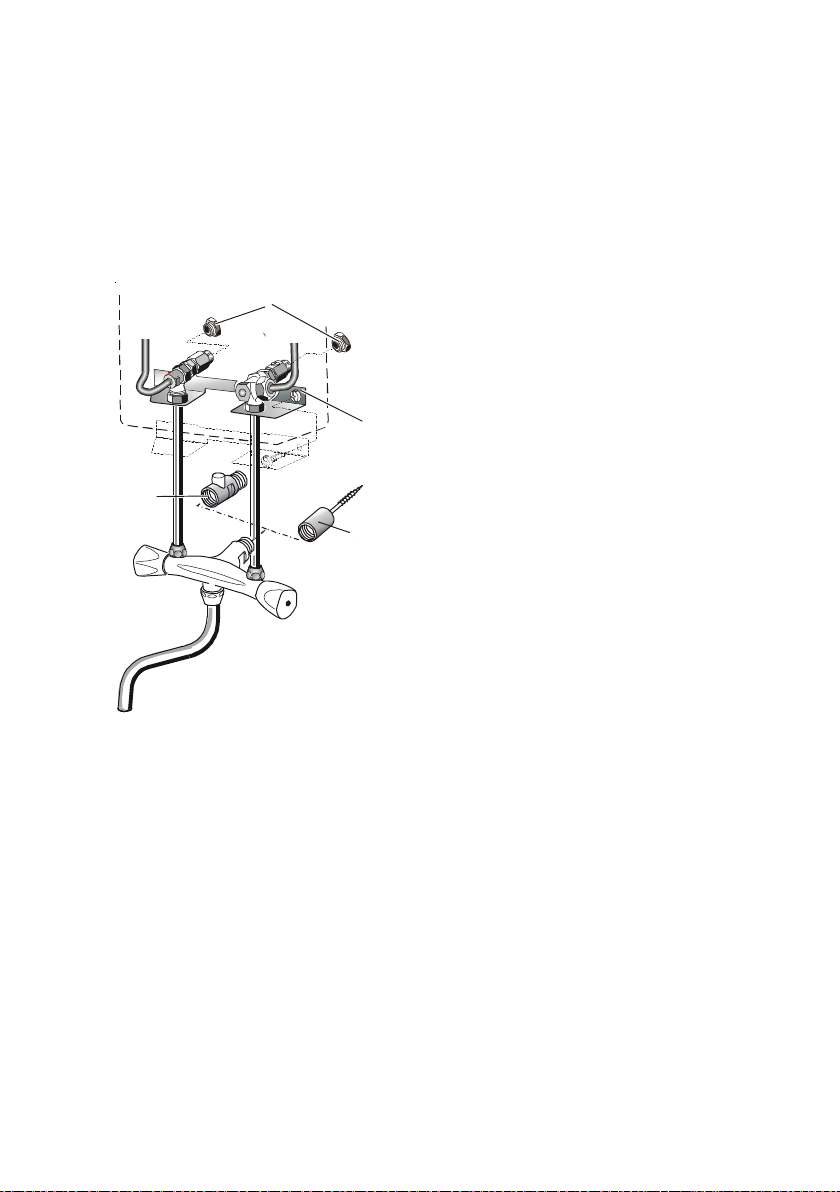
For fittings directly on the appliance, the bushing openings pre-embossed in
the appliance hood must be cut out for the extension pipes of the fitting. The
supporting sheet (1) enclosed with the fitting fixes the extension pipes in
position and seals the housing openings. To ensure moisture protection,
the supporting sheet must be fitted.
Fitting must be vertically seated and
centrally under the appliance. Seal
appliance connection to the wall, where
necessary, with G 1/2 A blind plugs (2)
(fitting accessory).
If a cold water supply is made to the
appliance, the shutoff adapter (3) should be
replaced by an adapter with a wood screw
(4) for fixing the fitting in place.
The following tapping fittings are suitable:
D 169 - Special mixer tap with swivelling outlet
D 159 - Special shower mixer tap
D 149 - Special bath mixer tap with change-over tub/shower
Important! After completion of the water installation, the appliance
should be thoroughly flushed with cold water (open the hot water
valve). The strainer insert may possibly need cleaning afterwards.
11
Page 12
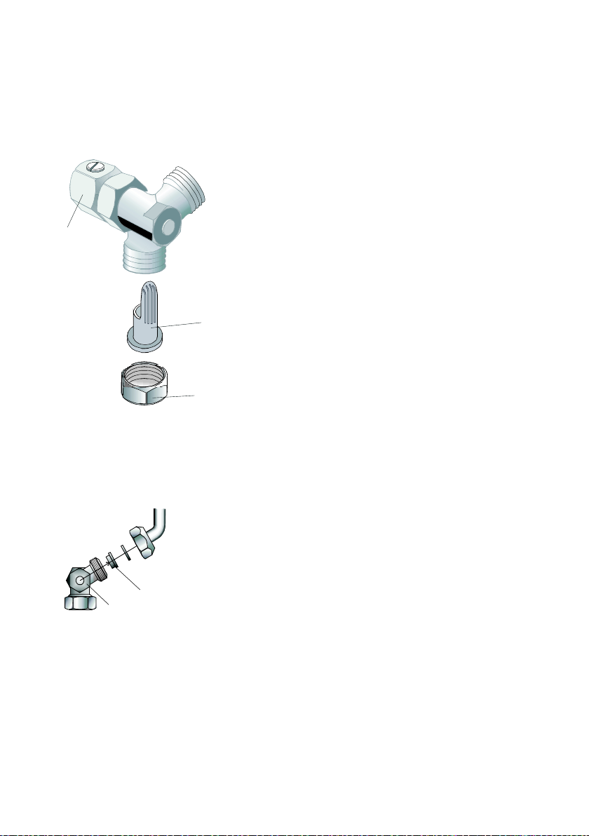
Cleaning the strainer insert
2
1
3
1
2
If the water flowrate is reduced by dirt from the cold water line, the strainerinsert should be cleaned as follows:
− Shut off cold water on shutoff unit (1)
− Loosen cap nut (2) using a spanner
− Take out and clean strainer (3)
− Re-assemble in reverse sequence
− Open cold water on shutoff unit (1); check
tightness
Flow rate limiter
The flow rate limiter (2) is installed in the cold
water connector (1) to allow a constant outlet
temperature at high flow pressures of approx. 40° C,
suitable for showering.
(See table page 4 and 6)
12
Page 13
Electrical connection
1
2
3
max.10
4
20
150
The electrical connection should only ever be made after the water is
connected! The appliance is only suitable for a fixed connection of
380 V 3 ~ (three-phase current) .
The appliance must be connected to the protective conductor.
Important note: The wiring must be arranged so that the appliance can be
de-energised (disconnected from the electricity supply) before any intervention
involving the fuses being unscrewed, the automatic safety devices being
switched off, or similar measures being taken (isolating gap width of at least
3 mm).
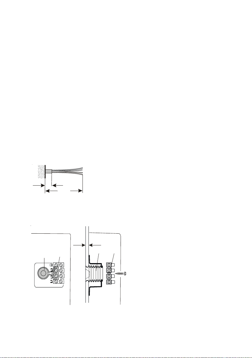
Mains connection lead
The connection cable must project from the wall
over an insulated length of at least 20 mm.
Mains connection on top
Electrical connection terminal (3)
factory-prefitted.
Cut out cable inlet opening (1).
Slide flexible inlet bush (2) over
connection cable, insert it through the
back wall opening, and screw fixing
strap under connection terminal (4).
13
Page 14
Mains connection underneath (alternative)
3
2
1
L1(R)
L2(S)
L3(T)
PE
Netzanschluß-
klemme
Heizblock
3
4
2
5
1
W4
W3
W2
W1
3
4
2
5
1
Elektronik
LED
1 2
IN
L1
L2
L3
K
S
D
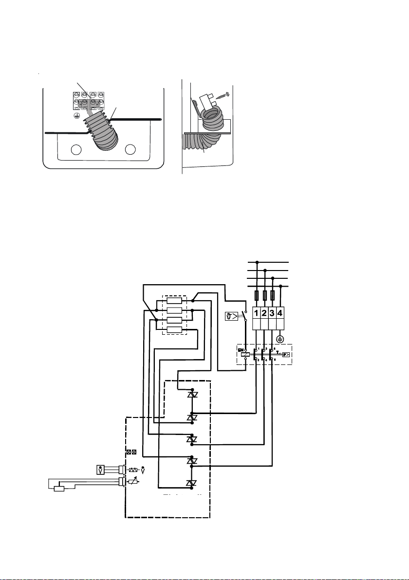
For this connection
version, transpose the
mains connection terminal
(1) from top to bottom.
Note the terminal
designation on the back
wall, and do not cross
the connection leads to
the safety temperature
limiter.
Carry out cable inlet opening
(2), inlet bush (3), and bush fixing under the mains connection terminal as
described above for mains connection.
Important! Moisture protection is only guaranteed with the inlet bush
fitted in position.
Circuit diagram
Heating block
Main connection terminal
Safetytemperature
and pressure
limiter
Electronic
system
14
Page 15
Temperature selector range limitation
3
2
1
IN
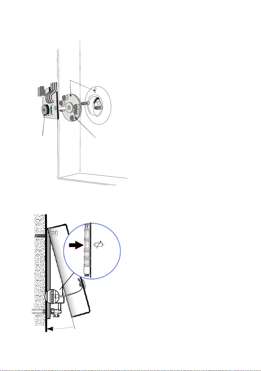
The maximum temperature able to be
set can be limited to 40°C or 45°C.
Important! Before dismantling, set
the knob to the minimum temperature of 30°C.
Detach the temperatur set-point pickup
(2) in the appliance hood. Turn the
setting dial (3) so that the printed setpoint coincides with the hood mark (1).
Do not twist the selector axis and
plate of the temperature set-point
pickup when reassembling!
Hood dismounting
Plug the connection lead of the
temperature set-point pickup into the
electronic system, suspend the appliance
hood in the upper edge of the back wall,
and swivel it downwards until it audibly
engages.
If necessary, the hood can be supplimentarily fixed with a screw next to the
engagement lug.
15
Page 16

Using the appliance for the first time and checking
The unit must be installed and started up by an approved firm of installers
which accepts liability for safety and proper function.
Before the appliance is energised (connected to the electricity supply),
it should be thoroughly flushed with cold water and the tightness of the
screwed joints checked.
After the instantaneous water heater is energised (connected to the
electricity supply), it should be inspected by a trained engineer to
ensure that it is in proper working order. For protection of the heating
systems, the system is arranged for a switch-on delay of 5 - 25 s at
initial startup and after the appliance has not been live for any length
of time.
Important: After any work carried out on the water supply unit, the
appliance should also be thoroughly flushed with cold water (vented)
before being switched on again. Only then should the appliance be
reconnected to the electricity supply.
After initial startup, the user should be familiarised with operation of
the appliance and the instructions for installation and use handed
over for safekeeping.
16
Page 17

Fault-finding (important instructions for the trained engineer)
In the event of any fault, a check should first be made to ascertain
whether the fuse and line protection switch have tripped.
CauseFault Remedy
- Heating system does
not switch on
- Hot water flowrate too
low
- Safety temperature and
pressure limiter has
tripped
- Active fault indicator
(LED)
- Appliance is not live
- Strainer insert is
clogged
- Soiling or scaling of
bubblers and shower
heads
- Defective heating
system
- Inadmissibly high cold
water inlet tempera ture (over 25 °C)
- Inadmissibly high
outlet temperature
(over 70 °C)
- System fault (see
table on page 18)
Check the voltage
Clean strainer insert (see
page 12)
Dismantle and clean the
bubblers and showers
heads
Inspection and repair only
by the trained engineer
Appliance should not be
operated with preheated
water.
Inspection and repair only
by the trained engineer
Inspection and repair only
by the trained engineer
17
Page 18
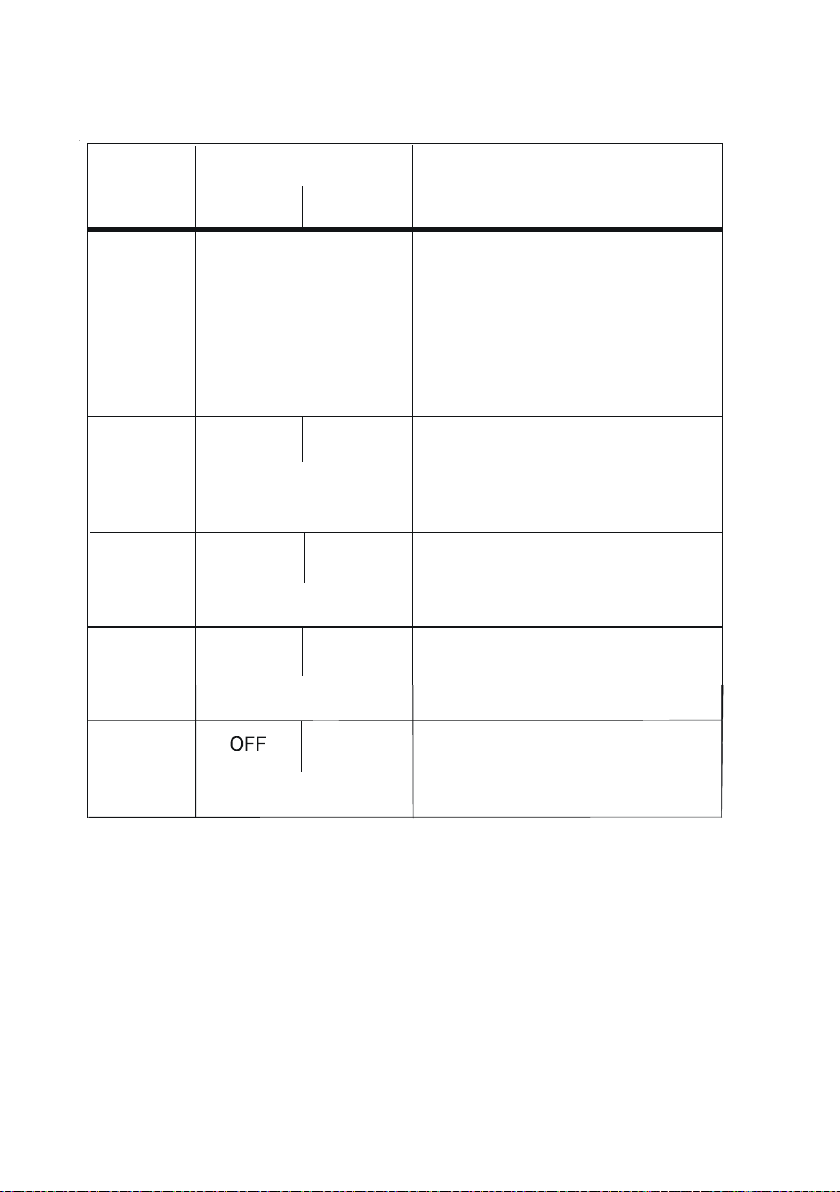
Fault indications
- L1 or L3 phase missing
- L2 phase missing
*) The individual fault are indicated every 5 sec. The indication mode starts
afresh every 40 sec.
Important! If the fault has been rectified, the fault memory goes automatically in Reset - Function.(Sometimes with cold water flow phase ca.15 sec.)
Fault
pattern
Idicator Possible faults
LED 1 LED 2
1 No display
Appliance does
not work
- Flowrate sensor not plugged
/ defective
Setpoint temperature
not reachd
2
FLASHES
long
FLASHES
long
- Setpoint generator not fitted
3
No display
warm water temp. 37°C
Constant
FLASHES
long
FLASHES
short
No heat output
- Electronics defective
FLASHES
long
ON
No heat output
4
- Supply temperature over 25°C
5
ON
No heat output
- Water flow over 20l/min
18
Page 19
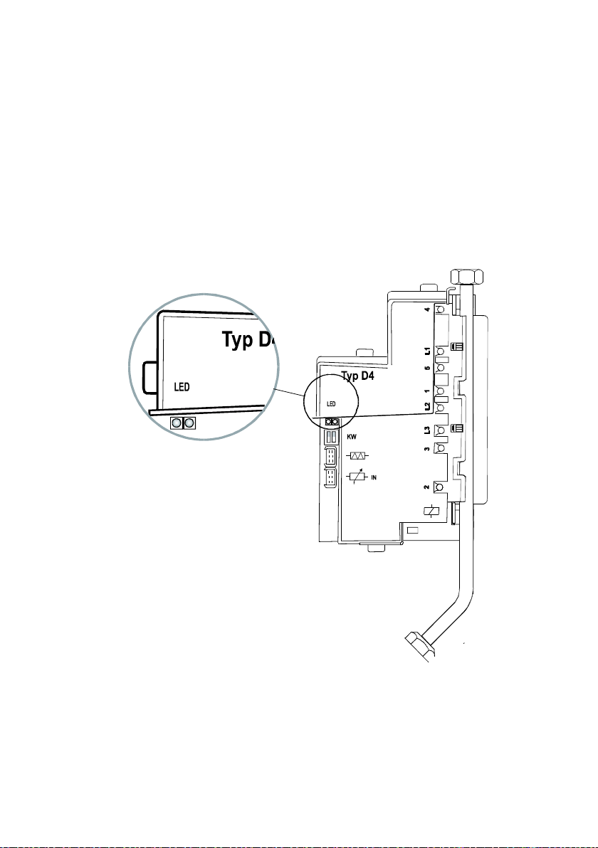
Important for the expert
V
1 2
1 2
Fehleranzeige
The electronic controls the safety-function of the appliance. When a fault is
noticed, the fault indicator (LED) blinks and the heating element is switched
off.
After the fault has been recitified, fault memory will be automatically cancelled
Instructions for the fault finding see in "Instructions for installation and use"
page 17and 18.
Fault indicator
19
Page 20
Customer service
Serial No.
If your appliance has a fault, please contact your customer service centre for
advice.
Electric appliances should only ever be repaired by a trained
electrician, since the user may be seriously endangered by
improper repairs.
A list of the addresses of customer service centres is attached.
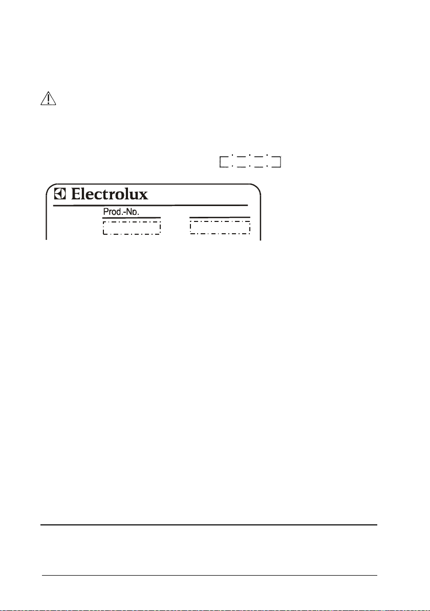
If your appliance requires service, you will need to quote these
numbers indicated on the rating plate.
To save enquiries, copy the data from the rating plate and keep them handy.
Subject to change
267789/K33895/8040
EHT Haustechnik GmbH
Gutenstetter Straße 10
D-90449 Nürnberg GERMANY
 Loading...