

Electrolux GPWBOEOOOO Installation Manual
Thermetic
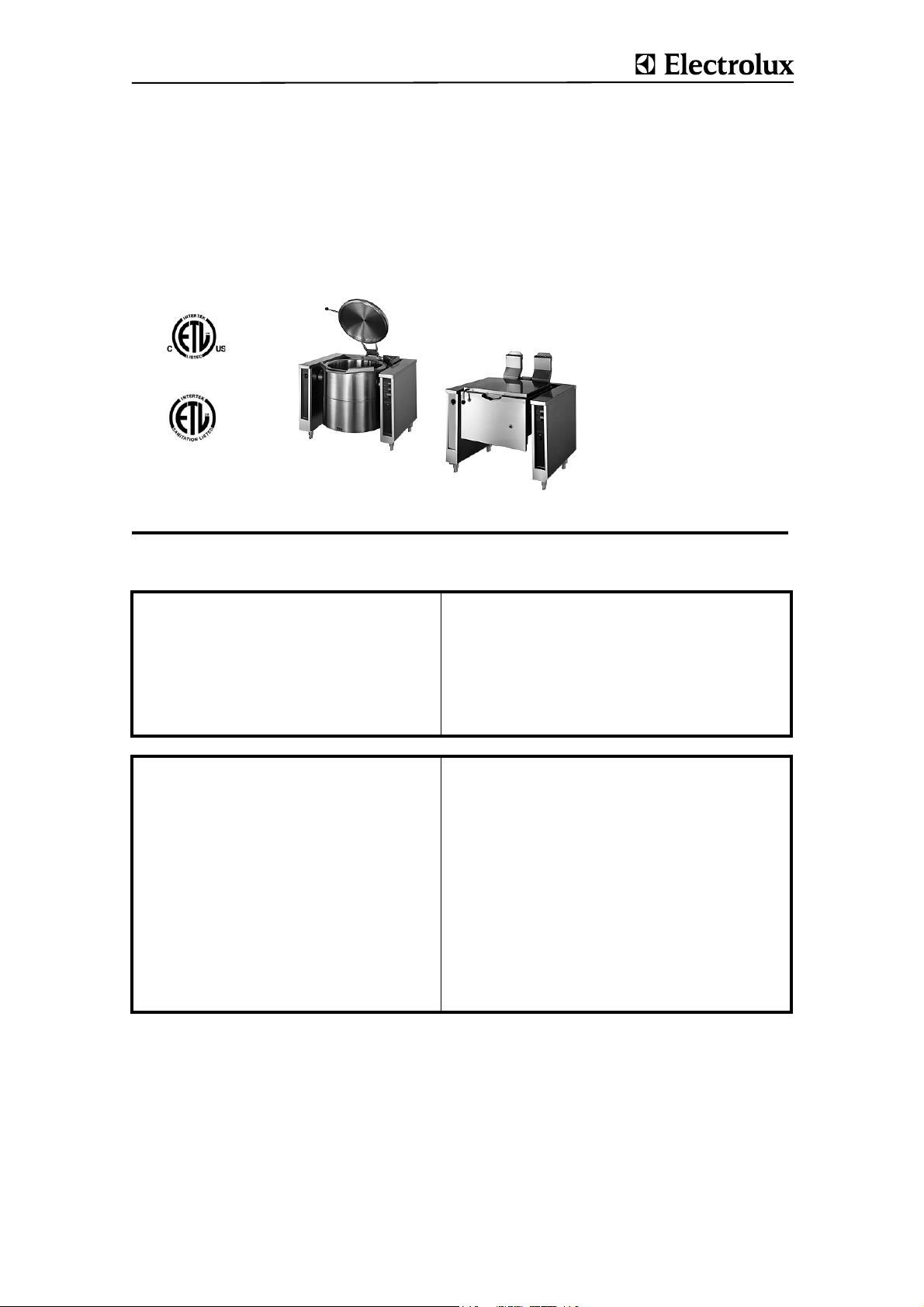
TILTING BOILING PANS, ROUND, GAS HEATED (GU........, KU........)
TILTING FRYING PANS, RECTANGLE, GAS HEATED (GP........)
US INSTALLATION - INSTRUCTIONS
Doc. 62.9699.01
Edition 1
09.2004
FOR YOUR SAFETY
Do not store or use gasoline or
other flammable vapors or
liquids in the vicinity of this or
any other appliance.
WA RN IN G
Improper installation, adjustment, alteration, service or
maintenance can cause property damage, injury or death.
Read the installation, operating
and maintenance instructions
thoroughly before installing or
servicing this equipment.
INSTRUCTION
Post in a prominent location instructions to be followed if the user smells gas. Consult
the local gas supplier to obtain the information.
Présentez dans des instructions en avant d'un endroit d'être suivi si l'utilisateur sent le
gaz. Consultez le fournisseur local de gaz pour obtenir l'information.
POUR VOTRE SÉCURITÉ
Ne déposez pas ou n'employez pas
l'essence ou d'autres vapeurs ou
liquides inflammables à proximité
de ceci ou d'aucun autre appareil.
AVERTISSEMENT
L'installation inexacte, l'ajustement, le changement, le service ou
l'entretien peuvent causer des blessures matériels, des dommages ou
la mort. Lisez les instructions
d'installation, d'opération et d'entretien complètement avant d'installer ou entretenir cet équipement.
CONTENTS
1. GENERAL REMARKS ........................................................................................................ 3
2. PACKAGING / TRANSPORT ..............................................................................................3
3. TECHNICAL DATA / DIMENSIONED DRAWINGS / INSTALLATION PLANS ................. 3
3.1 TILTING BOILING PANS ................................................................................................................. 3
4. FLOOR GULLIES ................................................................................................................5
5. MOUNTING / POSITIONING / FASTENING IN PLACE / ALIGNMENT .............................5
5.1 POSITIONING ................................................................................................................................... 5
5.2 ACCESS TO INSIDE THE CONSOLES AND SUPPORT ................................................................ 7
5.3 COVERS (PANELS) ......................................................................................................................... 7
6. INSTALLATION ................................................................................................................... 8
6.1 ELECTRICAL CONNECTION ........................................................................................................... 8
6.2 GAS CONNECTION ......................................................................................................................... 9
6.3 UNIVERSAL CONTROL PARAMETER SETTINGS ...................................................................... 10
6.4 THERMACAM / HACCP ................................................................................................................. 13
6.5 INSPECTION PROCEDURES / TEST OF FUNCTIONS ................................................................ 14
7. DECOMMISSIONING / DISMANTLING / DISPOSAL ....................................................... 14
62.9699.01 Page 1
1. GENERAL REMARKS
Responsibility
The setting up, adjustment and initial commissioning of appliances must be carried out in accordance with the manufacturer's instructions and may only be done by authorised
personnel. The installations for the electricity, steam, condensate, hot water, gas and water supplies as well as ventilation
must be laid or fitted by approved installation contractors in
accordance with specific national and local regulations. The
installation contractors are responsible for the correct layouts
and installations in conformity with all safety regulations. The
warning signs and specification plates fitted to the appliances
must be strictly adhered to.
The operator of this appliance is responsible for total observation of the national regulations concerning operating safety.
Validity
These instructions for installation refer to the THERMETIC tilting appliance program with appliances of different sizes: tilting
boiling pans, tilting braising pans and tilting pressure braising
pans.
Dimensioned drawings and installation plans of this document
are only for information purpose to the installers. These plans
may not be used for planning or projecting kitchens.
Tests/certificates
All gas appliances are tested according to the standards
ANSI/NSF 4 - 2002 of Commercial Cooking, Rethermalization,
and Powered Hot Food Holding and Transport Equipment and
ANSI Z83.11-2002 and CSA 1.8-2002 of Gas Food Service
Equipment.
2. PACKAGING / TRANSPORT
Types of packaging
Various types of packaging are used dependent on country of
destination. All versions of these appliances are transported
on a wooden frame or floor, are affixed to these with plastic
straps and located with wooden strips to prevent slipping.
Destination Overseas:
Version: Heavy, crate closed
Floor: Wooden floor
Floor fixing:
Side and cover frame:
Water and dust protection: Plastic film
Physical outer protection: Closed crate
Held together by: External steel banding
Transport: Forwarder
Stack ability: max. 4 appliances
Packaging markings
The external surfaces of the packaging have the following
markings which must be strictly adhered to:
• Forwarding label with the following information:
- Delivery company
- Delivery company's order number
- Customer's order number if available
- Delivery address
- Package number
- Net weight in kg
- Gross weight in kg
- External dimensions of the packaging
• Handling stickers with pictograms
- Umbrella = Keep dry; the packaged appliance
may not be stored outdoors
- Glass = Contents fragile
- Arrow pointing up = Only transport and store the
appliance in this position
- Stacking number = Number of appliances that can be
stacked (1 = cannot be stacked)
- Ice crystal and roof = Protect against frost
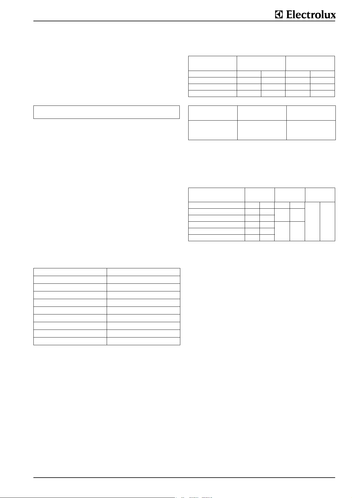
Transport weights
The precise gross and net weight is given on the forwarding
label:
Tilting boiling pans max. gross weight max. net weight
.U........ kg lb. kg lb.
080 LT (21.1 gal) 215 474 195 430
100 LT (26.4 gal) 250 551 230 507
150 LT (39.4 gal) 290 639 270 598
300 LT (79.3 gal) 410 904 390 860
Tilting braising pans max. gross weight max. net weight
.P........ kg lb. kg lb.
060 LT (15.9 gal) 230 507 210 463
080 LT (21.1 gal) 260 573 240 529
100 LT (26.4 gal) 290 639 270 595
Packaging dimensions
The precise external dimensions of the packaging are given on
the forwarding label attached to the outside of the packaging.
The maximum dimensions of the "European light" style of
packaging are given below:
Appliance size
LT
Tilting boiling pans 80, 100 1200 47.2 900 35.4
Tilting boiling pans 150 1300 51.2
Tilting boiling pans 300, 400 1500 59.1
Tilting braising pans 60 1200 47.2
Tilting braising pans100 1600 66.9
Width Depth Height
mm inch mm inch mm inch
1000 39.4
900 35.4
900 35.4Tilting braising pans 80 1400 55.1
Handling
Both packaged as well as unpacked appliances are best lifted
and transported whenever required with a pallet truck which is
inserted into the wooden frame or under the wooden base.
This applies to both the loading and unloading of trucks as well
as to handling operations on the installation site.
For handling by a crane, the unpacked appliances do not have
any specific lifting points to which they can be attached. It is
necessary to wrap two straps or ropes around the appliance
when lifting is required. Wrapping straps or ropes around the
appliance may only be done at the sides and not round the
front and the rear. The straps or ropes should be arranged
approximately 150 mm (5.9“) from the outer edges.
3. TECHNICAL DATA / DIMENSIONED DRAWINGS / INSTALLATION PLANS
These illustrations are not intended for the planning and laying
of the supply lines in the building.
3.1 TILTING BOILING PANS
Style of mounting Floor mounting with feed
Tilting Motor tilting with lifting motor
PROCESS COMFORT control system with cooking tem-
Control system
Protective system hose proof IP X5
perature control and
programmable cooking and
starting time.
Manual control for steam
heated boiling pans.
62.9699 Page 3

3.1.1 Gas heated tilting boiling pans (.U........))
80 LT,
gas heated
Heating capacity (gas) kW 18 21 27 45
Elect. motor tilting
Wattage in kW
Voltage (V), Current in A
0,2
230V/1~N,60 Hz, 0,7 A
100 LT, g
as heated
150 LT,
gas heated
300 LT,
gas heated
Mains connection 120V/1~N/60Hz
Necessary gas flow per appliance:
80 LT,
gas heated
Natural gas H m3/h 1.87 2.18 2.80 4.67
Natural gas L m3/h 2.16 2.53 3.25 5.42
Propane kg/h 1.50 1.74 2.24 3.73
Butane kg/h 1.52 1.77 2.27 3.79
100 LT, g
as heated
150 LT,
gas heated
300 LT,
gas heated
Dimensioned drawings for tilting boiling pans (.U........)
L Length to floor gully
N Depth of floor gully
Installation plans for tilting boiling pans (.U........), tilting
frying pans (.P........), tilting braising pans (.X........)
Fig. 1 Dimensioned drawings for tilting boiling pans
Pan size in litres
80 100 150 300
Dimensions mm
A
B
C
D
E
F
G
H
J
K
L
M
N
1200 1200 1300 1500
1073 1096 1224 1352
1034 1060 1190 1290
579 640 710 900
385 395 465 570
900 900 900 900
476 450 420 320
80 88 97 110
680 680 780 780
900 900 1000 1000
710 710 710 810
330 330 330 430
1000 1000 1000 1200
A Width of appliance (see
dimensioned drawing)
E Electrical cable protruding
from wall
W Hot water connection G
1/2", NW15
K Cold water connection G
1/2", NW15
G Gas connection 1"
Fig. 2 Installation plans for tilting boiling pans, tilting
frying pans, tilting braising pans
3.1.2 TILTING FRYING PANS (.P........)
Model (optional) Pan bottom made of steel or chrome-nickel
plated steel
Style of mountingFloor mounting with floor support with con-
sole.
Tilting Motor tilting with lifting motor
Control system Electronic control system with pan-base and
cooking temperature control and program-
mable cooking and starting time.
Tilting Frying Pans
Type 060 LT,
electric
Dimension A (mm) 1200 1400 1600
(inch) 47.2 55.1 63
Braising surface (mm)
(inch)
Pan depth in (mm)
T(inch)
Net content (litres)
(gal)
max. capacity
Heating capacity (gas) kW 16 20 26
Elect. motor tilting
Wattage in kW
Voltage (V), Current in A
600 x 600
23.6x23.6
200
7.9
63
16.4
0,2
230V/1~N,60 Hz, 0,7 A
080 LT,
electric
800 x 600
31.5
200
7.9
84
22.2
100 LT,
electric
1000 x 600
39.8
200
7.9
104
27.5
Mains connection 120V/1~N/60Hz
Dimensioned drawings
H Height for all types 900 mm (35.4“)
S Height of feet / wheel 200 mm (7.9“)
Page 4 62.9699

5. MOUNTING / POSITIONING / FASTENING IN PLACE / ALIGNMENT
In principle, the appliance must be installed in its scheduled
location in accordance with the valid plans. The appliance is
scheduled for connection to fixed power- and water supplies.
The installation dimensions are given on the plans.
The appliances are suitable for setting up as single appliances
or as a group of appliances. They can be set up freely in the
room, side by side, at the side and/or at the back against a
wall.
Gas-heated appliances may only be set up in adequately ventilated rooms. A ventilation engineer is responsible for the
assessment or planning of a ventilation system that fulfils
safety regulations.
Fig. 3 Dimensioned drawings
Tilting frying pans
Installation plan see 3.1.
4. FLOOR GULLIES
In the case of tilting appliances, floor gullies with loose gratings
and floor drains which serve as drains when cleaning are provided for near to the outlet. Floor gullies can be designed for a
single appliance or for a whole group of appliances. There is a
very wide variety of types and sizes. Please consult the relevant installation plans for information concerning layout and
type.
In general, the floor gullies with their drains are concreted into
the floor by the builder.
A Pan sizes 80 to
150 litres; Grating 500 x 1000
mm (19.7x39.4“)
B Pan sizes 200 to
400 litres; Grating 600 x 1200
mm (23.6x47.2“)
Fig. 4 Sample dimensions of individual floor gullies for
tilting boiling pans without drain valves.
Distances/walls
These may not be positioned against combustible walls. If an
appliance is set up next to or against temperature-sensitive
furniture or similar, a safety gap of approximately 50 mm (2“)
should be maintained or some form of heat insulation fitted.
When setting up an appliance in the close vicinity of walls, partitions, kitchen equipment, decorative cladding, etc., it is recommended that the latter are made of incombustible material
or that they are clad in a suitable, incombustible material or
tiled. The regulations governing fire protection must be
adhered to as closely as possible.
Preparation for fastening in place
Before the appliance is brought to the correct place and put in
position, the following connection points must be prepared
dependent on the type of appliance:
• Fastening elements, i.e. drilling holes and inserting plugs.
Explanations for this are included in the relevant sections
under "Fastening".
• Prepare the water connections and, possibly, fit a shut-off
valve.
• Prepare the gas connection and, possibly, fit a shut-off
valve and a filter.
Setting up
The appliance should be transported to the place where it is to
be set up in accordance with § 2
.
Removal of the packaging:
The packaging should not be
removed until immediately before
the appliance is to be set up in
place. All side and top packaging
parts as well as the fastening elements must be removed in
sequence. The appliance should
remain on its wooden transport
frame or base until at the site for
installation.
5.1 Positioning
Transport the appliance on its
wooden frame to a point directly in
front of where it is to be set up. The
installation connections protruding
from the floor should be at the side
as close as possible to the wooden
frame.Slide the appliance off the
wooden frame so that all the installation connections are within the
appliance.
Fig. 5 Typical, floor gully for a single appliance with a siphon
(S) made of stainless steel (728 342 984)
62.9699 Page 5
 Loading...