

Electrolux ELWADREW5271, EXWADRGW4271, EXWADREW6271 Data Sheet
This information is intended for Qualified Technicians Only.
10
2
3
5
6
TABLE OF CONTENTS
Washer Tech Data Sheet ....................................................................... 1
Diagnostic Mode Tests .......................................................................... 2
Demo Mode .......................................................................................... 3
Washer Error Codes .............................................................................. 3
Troubleshooting Tests ............................................................................ 5
Wiring Diagrams .................................................................................. 19
Washer Tech Data Sheet
CAUTION
Unless otherwise directed, disconnect electrical current before
servicing.
WARNING
1
Safety items throughout this manual are labeled with a WARNING or
CAUTION based on the risk type as described below:
WARNING
CAUTION
This symbol alerts you to situations that may
cause serious body harm, death or property
damage.
This symbol alerts you to situations that may
cause bodily injury or property damage.
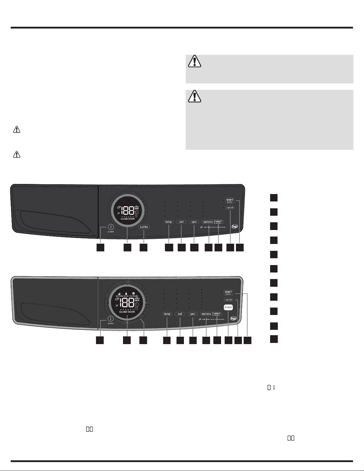
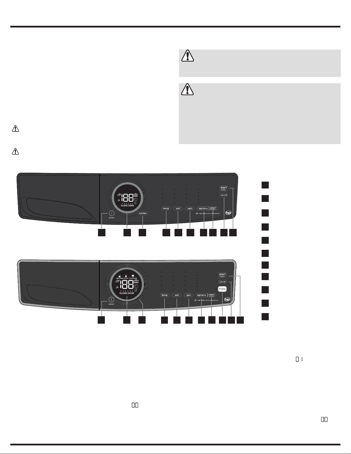
Push Button Cycle Select Washer User Interface
21 63 854 9 10
Rotary Dial Cycle Select Washer User Interface
The information within this manual is intended for Qualified
Service Technicians Only.
• DO NOT reach into the appliance while the tub or drum is
spinning.
• Disconnect power before servicing machine.
• Certain internal parts are intentionally not grounded and may
present a risk of electric shock only during servicing.
power
1
cycle status display
cycle selector
temperature
4
7
soil level
spin speed
1
2
3 8
Entering Diagnostic Mode:
1 Press power to turn machine on.
2 Rotate cycle selector ring (on some models) or repeatedly press
cycle button (on other models) to set cycle to normal.
3 Press the start button.
4 Power off machine by pressing the power button.
5 Power on machine by pressing the power button again.
6 Within 10 seconds, simultaneously hold temp + select (set) buttons
together for 3 seconds.
7 Diagnostic Mode is active when LED’s start blinking in sequence.
This is the pre-test position “ ”, which tests the lights and buttons.
USA 1-877-435-3287
www.electroluxappliances.com
options
7
select (set)
8
cancel
9
start/pause
10
®
PODS
7
6
54
11
10
9
11
Scrolling through Diagnostic Mode tests:
Tests are selected by using the same method to select cycles. See Diagnostic Mode Tests Table.
To begin, press and hold the cycles button for 2 seconds. The unit will
advance to the first test; and flash “ ” on the display.
Press the cycles button to advance to the following test. Press the
temp button to go back to the previous test. Test sequence numbers
are briefly displayed when each test is selected. The displayed test numbers also correspond to the selector LEDs to the right of the numeric
display; beginning with the top LED, following downward.
Exiting Diagnostic Mode:
Hold the power key for 3 sec, when not in “ ” test step Lights/Buttons, or unplug the unit.
A11200302 (1803)
Canada 1-800-265-8352

2
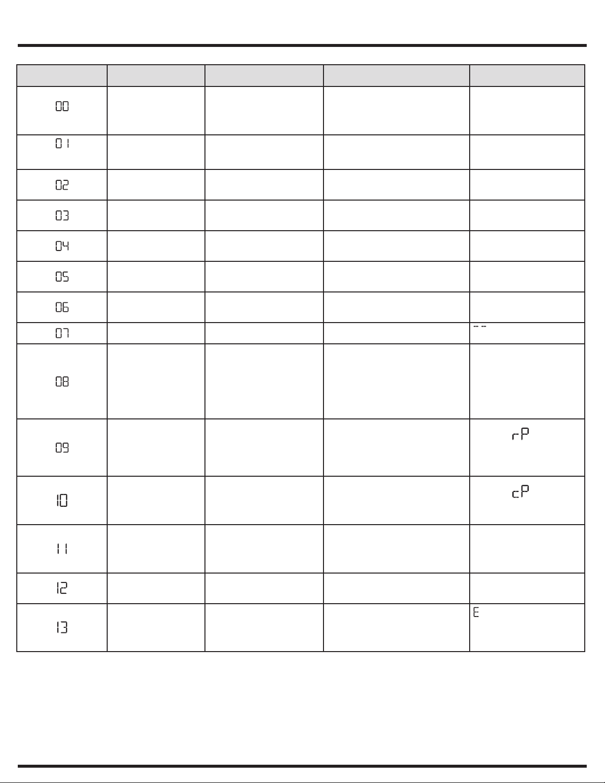
Diagnostic Mode Tests
MODE
NUMBER
(select models only)
TEST NAME COMPONENTS UNDER TEST TEST CONDITIONS DISPLAYED FEEDBACK
Lights, Buttons • LED indicators
PODS® compartment
(no test for 400 series)
Wash compartment • Door lock
Bleach compartment • Door lock
Softener compartment • Door lock
Stain compartment • Door lock
Wash compartment • Door lock
Door unlock • Drum light Drum light turns on when door is open.
Heater & motor • Pressure sensor
Recirculation Pump
(no test on 400 series )
Concentrate wash pump
(no test on 400 and 500
series)
Drain pump & spin • Drain pump
All valves on • Door lock
Error history • The last 3 errors in memory Errors are displayed in order of history
* Note for diagnostic mode only: The door is locked in the spin test step, however it can unlock without delay in another test step or on
exiting diagnostic mode, when opening the door the drum can have energy as it spins down.
• LCD screen
• Button response
• Door lock
• PODS® valve
• Hot valve
• Bleach valve
• Prewash valve
• Bleach valve
• Prewash valve
• Cold valve
• Cold valve
• Motor
• Heater
• NTC
• Door lock
• Drum light
• Recirculation pump
• Pressure sensor
• Cold valve
• Motor
• Door lock
• Drum light
• Concentrate wash pump
• Door lock
• Drum light
• Motor
• Door lock
• All valves
Valve stays on until water level reaches
20 liters. Then door remains locked for
5 minutes.*
Valve stays on until water level reaches
140 mm. Then door remains locked for
5 minutes.*
Valve stays on until water level reaches
140 mm. Then door remains locked for
5 minutes.*
Valve stays on until water level reaches
140 mm. Then door remains locked for
5 minutes.*
Valve stays on until water level reaches
140 mm. Then door remains locked for
5 minutes.*
Valve stays on until water level reaches
140 mm. Then door remains locked for
5 minutes.*
Motor moves after machine fills with
60 mm of water. Heater heats
until temperature reaches 70º C.
Max. duration of test is 8 minutes.
Need power meter to check heater
functionality.
Motor moves after machine fills with
140 mm of water. Recirculation pump
turns on. Max. duration of the test is 8
minutes.
Concentrate wash pump turns on for
max. 5 minutes. Need power meter
to check concentrate wash pump
functionality.
Drain pump turns on until empty, then
motor starts spinning at max. rpm for 30
seconds. Then door remains locked for
6 minutes.*
Valve stays on until water level reaches
140 mm. Then door remains locked for
5 minutes.*
(most recent first).
Note: Pressing temp + select (set)
buttons together clears error history.
Number of key pressed.
Note: This number may not
necessarily correspond to key
number on table on page 1.
Water level
Water level
Water level
Water level
Water level
Water level
NTC reading
Display
Display
Display (drum speed/10)
water level
precedes the 2 character
alarm code, alternating through
the alarms

Demo Mode/Washer Error Codes
3
Demo Mode:
The Demo works in two ways: Interactive Mode and Automatic Loop.
The Interactive Mode enables the customer to use the interface
without activating the appliance. The machine behavior appears similar
to normal operation. With the door closed, pressing start, the appliance
turns on and the display counts down by the second from the maximum
time displayed with its respective cycle. The appliance turns off when it
reaches “ ”.
The Automatic Loop will engage if no one interacts with the user interface for 3 minutes, or the start button hasn’t been pressed. The machine
will simulate a cycle execution on the display only.
Entering Demo Mode:
1 Press power and look for console light up.
2 For Rotary Dial Cycle Select Washer: Within 10 seconds select
fast wash and then simultaneously press and hold temp and select
(set) buttons for 3 secs. Skip to Step 4.
3 For Push Button Cycle Select Washer: Within 10 seconds select
rinse & spin and then simultaneously press and hold temp and
select (set) buttons for 3 secs. Continue to Step 4.
4 The message “ ” will blink 3 times in the center display.
5 If “ ” message does not appear, turn off machine and repeat
previous steps.
NOTE
Once Demo Mode is activated, every time the machine is turned on,
Demo Mode is automatically recalled; this occurrence is signaled at
the start-up by the text “ ” flashing 3 times in the center display.
Unplugging the unit will not clear Demo Mode. See “Exiting Demo
Mode” for more information.
Washer Error Codes
Error
Code
11 Fill time too long Yes Refer to test (1)
13 Water leak in tub or in pressure sensor No Refer to test (2)
21 Water not pumping out fast enough Yes Refer to test (3)
23 Drain triac error No Refer to test (3)
24 Drain triac error sensing No Refer to test (3)
31 Electronic pressure switch error No Refer to test (4)
32 Pressure sensor calibration problem No Refer to test (4)
35 Pressure sensor indicates water overfill No Refer to test (5)
38 Air trap clogged No Refer to test (5)
41 Control board thinks the door switch is open Yes Refer to test (6)
42 Door lock device failure No Refer to test (6)
43 Door lock triac failure No Refer to test (6)
44 Door closed sensing failure No Refer to test (6)
45 Line door sensing failure No Refer to test (6)
55
(select models)
57 High current on inverter (motor control) No Refer to test (8)
58 High current on motor phase No Refer to test (8)
59 No spin signal for 3 seconds No Refer to test (9)
5A High temperature on control due to overload (motor control) No Refer to test (8)
5B Motor control under voltage No Check supply under load and wiring to unit
Error Description Display
Motor under speed
(not available on 300 series)
Exiting Demo Mode:
To exit Demo Mode, perform the same sequence used to enter Demo Mode.
1 Press cycles to advance the cycle selection to Delicates.
2 Press start; then Press cancel.
3 Press power to turn the unit off.
4 Press power to turn the unit on. The unit will display will flash “ ”
3 times on the numeric display.
5 Press and hold temp and select (set) simultaneously. The appliance
will beep once, the numeric display will cycle off and on. The appliance will then beep with the normal power on sequence.
You may also perform a Factory Default Reset - see below.
Factory Default Reset:
1 Press power and look for console light up.
2 Wait at least 10 seconds, then simultaneously press and hold soil
and options buttons for 3 secs.
To return to factory settings,
press the soil and options buttons at
the same time and hold until the signal
sounds.
Recalling Last Error Code:
1 Press power and look for console light up.
2 Wait at least 10 seconds, then simultaneously press and hold temp
and select (set) buttons for 3 secs.
3 The display will show the last error in memory.
4 Clear the display and return to normal operation by touching any
button or by pressing the power button.
Notification
No Check for heavy or unbalanced load
Next Step
Refer to test (9)
Refer to tests (6 and 9)
4
Washer Error Codes
Washer Error Codes, continued
Error
Code
5C High Voltage experienced by motor control board No Refer to test (12)
5D Communication problem with motor control (message) No Refer to test (10)
5E Communication problem from motor control (communication failure) No Refer to test (10)
5F MC is continuously resetting No Refer to test (10)
62 Wash temperature too high No Refer to tests (13 and 14)
66
(on select models)
68
(on select models)
69
(on select models)
6A
(on select models)
71
(on select models)
74 Wash temperature does not increase No Refer to tests (13 and 14)
83 Wrong selector reading No Refer to test (10)
84
(on select models)
85
(on select models)
86 Incorrect UI selection table No Refer to test (11)
87 User interface micro-controller fault No Refer to test (11)
88
(on select models)
91 User interface protocol incongruence error Yes Refer to test (11)
92 User interface mother board protocol incongruence No Refer to test (11)
93 Console or main board control problem (incompatible machine
94 Main board control problem (incompatible cycle configuration) Yes Refer to test (10)
97 Console or main board control problem (incompatible cycle
98 Incompatible motor control/main board No Refer to test (10)
9C User interface configuration problem Yes Refer to test (11)
9E Touch sensor on user interface not responding No Refer to test (20)
H1/B1 Frequency of power out of limits Yes Refer to test (18)
H2/B2 Supply voltage too high (incoming voltage) Yes Refer to test (18)
H3/B3 Supply voltage too high (incoming voltage) Yes Refer to test (18)
HE/BE Control Relay fault No Refer to test (18)
HF/BF Control relay sense fault No Refer to test (18)
F2 Too much soap or wrong type Yes Advise customer to reduce detergent or change to
F5 Load unbalanced No Redistribute load and restart
F6 Control reset No Refer to test (19)
F9 Hot valve warning - hot water and cold water hoses reversed No Reverse the water hoses to reduce the risk of water
Error Description Display
Notification
Heater relay problem No Refer to test (14)
Current leakage to ground on heater or wiring No Refer to test (14)
Heater open No Refer to test (14)
Heater relay sensing problem No Refer to test (14)
Drum water NTC failure. (tub heater) No Refer to test (13)
Recirculation pump triac sensing failure which stops the cycle No Replace main board
Recirculation pump triac alarm which stops the cycle No Refer to test (21)
Concentrated wash pump triac alarm No Refer to test (22)
Yes Refer to test (11)
configuration)
Yes Refer to test (11)
configuration)
Next Step
high efficiency, type
temperature related problems with the load
Troubleshooting Tests
5
Test
Number
Test 1 1. Is the incoming water flow normal? Yes, go to step (4).
Test 2 1. Is the washer leaking water? Yes, correct water leak.
Test 3 1. Check the drain hose for restrictions. If there is a restriction, correct the problem.
Test 4 Inspect the wiring between the pressure sensor and the main
Test 5 1. Is the water level above 4.5 inches? Yes, go to step (2).
Test 6 1. Is the loading door closed? No, close the door.
Check/Test Activity Steps Correction
No, go to step (2).
2. Are the incoming water faucets turned on? No, turn water faucets on.
3. Is the incoming water pressure above 20 psi? No, have customer correct pressure problem.
4. Does the fill water continue to enter the washer? Yes - Go to step (5)
5. Remove power from the washer. Did the water fill stop? Yes - Go to step (6)
6. Replace the pressure sensor. If this did not correct the problem, go to step 7.
7. Replace the main control board.
2. Is there an air leak in the pressure sensor system? Yes, correct the air leak problem.
3. Replace the pressure sensor. If this did not correct the problem, go to step (4).
4. Replace the main control board.
2. Start the washer and check for 120 VAC at the drain pump. If reading zero, check the wiring. If wiring good, replace the main control board.
control board.
2. Does water enter the washer continuously? Yes, go to step (3).
3. Remove power from washer. Does the water stop coming in? No, replace water valve assembly.
4. Replace the pressure sensor switch. Did this correct the
problem?
2. Can you hear the lock attempt to close? Yes, check the door strike. If good, replace the door
3. Check wire connection between door lock and main control
board.
Yes, go to step (3).
Yes, check for kinked or blocked incoming water hoses, clean the incoming water
screens. If problem still remains, replace the water inlet valve assembly.
No - Go to step (6)
No - Replace the inlet valve assembly. If pressure switch checks good, go to step
(7). If pressure switch checks bad, replace pressure switch.
No, go to step (2).
No, go to step (3).
No restriction, go to step (2).
If reading 120 VAC, remove the pump and check for blockage. If blocked, remove
the restriction, if not, replace the pump.
If wiring defective, correct wiring.
If wiring OK, replace pressure sensor. If this does not correct the problem, replace
the main control board.
No, go to step (4).
No, check air trap for clog, if not replace the main control board.
Yes, check wiring to valve assembly for shorts. If wiring is good, replace the main
control board.
Yes, problem solved.
Yes, go the step (2).
No, go the step (3)
If good, replace the door lock. Then if problem is not fixed, replace the main
control board.
6
Troubleshooting Tests
Washer Troubleshooting Tests, continued
Test 8 1. Find out if the unit was overloaded. If not, remove the belt from
the motor and spin the motor pulley. Does the motor spin free?
2. Spin the tub pulley. Does the tub spin free? No, check the tub bearings.
3. Disconnect the plug from the motor and measure the resistance
of the windings (pin 1 to pin 2, pin 1 to pin 3, pin 2 to pin 3).
All readings should be between 3 and 6 Ohms.
Test 9 1. Remove the belt from the motor and spin the motor pulley.
Does the motor spin free?
2. Spin the tub pulley. Does the tub spin free? No, check the tub bearings.
3. Disconnect the plug from the drive motor and measure the
resistance between pins 4 & 5 in the motor.
4. Disconnect the plug from the motor and measure the resistance
of the windings (pin 1 to pin 2, pin 1 to pin 3, pin 2 to pin 3). All
readings must be between 3 and 6 Ohms.
Test 10 Communication problem. Check the wiring between the main
control board and the motor control board.
Test 11 Communication problem. Check the wiring between the main
control board and the user interface board.
Test 12 Have the power company or professional check the frequency and
voltage of the incoming power under load.
Test 13 Check the resistance of the water NTC. Is it around 4.8K ohms? No, replace the NTC sensor
Test 14 1. Check the resistance of the heating element. It should be ap-
proximately 14 ohms.
2. Check the resistance between ground and both heater terminals. It should be open when the heater terminals are disconnected.
Test 15 Check wiring between the main control board and motor control
board.
Test 16 1. Are the hot and cold water hoses switched? Yes, switch the hoses to correct position
2. Is the HOT water about the same temperature as the cold? Yes, fix the HOT water in the house supply.
Test 17 1. Check wiring between main board and pump. If OK, then go to step (2).
2. Check wiring between main control and recirculation board. If OK, then go to step (3).
3. Check pump for open coil (resistance check). If OK, then replace main control.
Test 18 1. Check power in for voltage under load. Correct supply or branch circuit issues.
2. Check power wiring to main board. Yes, fix wiring or plug to main board.
3. Check wiring to motor board for short to power or ground. Yes, fix problem.
Test 19 Check wiring to main board. Unplug the unit for 1 minute and retry. If problem is not corrected replace main control.
Test 20 Unplug and re-seat connector between UI boards. If problem persists, replace UI satellite board.
Test 21 Check wiring to recirculation pump If wiring is bad, correct wiring problem.
Test 22 Check wiring to concentrated wash pump If wiring is bad, correct wiring problem.
No, replace the motor.
Yes, go to step (2).
Yes, go to step (3)
If the readings are correct, check wiring from motor to motor control board,
If good, replace the motor control board. If the readings are incorrect, replace
the motor.
No, replace the motor.
Yes, go to step (2).
Yes, go to step (3).
If the meter reads other than between 105 to 130 Ohms, replace the motor. If the
reading is between 105 to 130 Ohms, go to step (4).
If the readings are correct, replace the motor control board.
If the readings are incorrect, replace the motor.
If wiring is bad, correct wiring problem.
If wiring is good, replace the main control board. If the problem is not corrected,
replace the motor control board.
If wiring is bad, correct wiring problem.
If wiring is good, replace the user interface board. If the problem is not corrected,
replace the main control board.
If correct, for error code E5C, replace the motor control board.
If correct, for error codes H1/B1, H2/B2, H3/B3, HE/BE, or H5/B5 replace the
main control board
Yes, check the wiring.
If the reading is incorrect, replace the heating element.
If the reading is correct, move to the next step.
If the readings are incorrect, replace the heating element. If the problem is not
corrected, check the wiring, If wiring is OK, replace the main control board.
If wiring is good, replace the motor control board.
No, go to step 2
No problem go to step 2.
No, go to step 3.
No, replace the main board.
If wiring is good, replace recirculation pump. If the problem is not corrected,
replace the main control board.
If wiring is good, replace concentrated wash pump. If the problem is not
corrected, replace the main control board.
Fiche technique de la laveuse
10
Ces informations sont destinées uniquement aux techniciens qualifiés.
TABLE DES MATIÈRES
7
Fiche technique de la laveuse ................................................................ 7
Tests du mode diagnostic ...................................................................... 8
Mode démo ........................................................................................... 9
Codes d’erreur ...................................................................................... 9
Tests de dépistage .............................................................................. 11
Schéma de câblage ............................................................................. 19
Les mesures de sécurité présentées dans ce guide sont identifiées
parles mots AVERTISSEMENT ou ATTENTION selon le type derisque
présenté ci-dessous :
Ce symbole signale les situations qui
AVERTISSEMENT
pourraient entraîner des dommages
matériels, des blessures graves ou la
mort.
Ce symbole signale les situations qui
ATTENTION
pourraient entraîner des blessures
ou des dommages matériels.
Interface utilisateur des laveuses avec sélecteur à touches
21 63 854 9 10
Interface utilisateur des laveuses avec sélecteur à bouton
1
2
3 8
ATTENTION
Sauf indication contraire, débrancher le courant électrique avant
d'effectuer l'entretien.
AVERTISSEMENT
Les informations contenues dans le présent manuel sont
exclusivement destinées aux techniciens d’entretien qualifiés.
• NE PAS ouvrir l’appareil lorsque la cuve ou le tambour tourne.
• Débrancher le cordon d’alimentation avant de procéder à l’entretien
de la machine.
• Certaines pièces internes ne sont pas mises à la terre délibérément
et peuvent présenter un risque d’électrocution uniquement lors de
l’entretien.
power
1
(marche/arrêt)
cycle status display
2
(affichage de l'état du cycle)
cycle selector
3
(sélecteur de cycle)
temperature
4
7
7
6
54
11
10
9
(température)
soil level
5
(niveau de saleté)
spin speed
6
(vitesse d'essorage)
options
7
select (set)
8
[sélectionner (régler)]
cancel
9
(annuler)
start/pause
10
(démarrer/pause)
®
PODS
11
(capsule de détergent)
Pour le mode diagnostic :
1 Appuyer sur power pour mettre la machine sous tension.
2 Tourner le bouton sélecteur de cycle (certains modèles) ou appuyer
sur la touche cycle (d'autres modèles) pour régler le cycle à normal.
3 Appuyez sur la touche start.
4 Mettre la machine hors tension en appuyant sur la touche power.
5 Mettre la machine sous tension en appuyant sur la touche power
denouveau.
6 Dans un délai de 10 secondes, appuyer simultanément sur les
touches temp + select (set) pendant 3 secondes.
7 Le mode diagnostic est activé lorsque les LED commencent
àclignoter en séquence. Voici la position prétest «», qui teste
lesvoyants et les touches.
États-Unis 1-877-435-3287
Pour naviguer les tests du mode diagnostic :
Les tests sont sélectionnés de la même manière que pour sélectionner
les cycles. Voir le tableau des tests du mode diagnostic.
Pour commencer, appuyer et tenir la touche enfoncée cycles pendant
2 secondes. L'appareil passera au premier test; et « » clignotera sur
l'affichage.
Appuyez sur la touche cycles pour passer au test suivant. Appuyez
sur la touche temp pour revenir au test précédent. Les numéros
de séquence des tests sont affichés brièvement lorsqu'un test est
sélectionné. Lesnuméros affichés correspondent également aux DEL
de sélection à la droite de l'affichage numérique, en commençant par
lepremier DEL en descendant.
Pour quitter le mode diagnostic :
Tenir la touche power enfoncée pendant 3 sec, pas en mode « » de
l'étape du test voyants/touches, ou débrancher l'appareil.
www.electroluxappliances.com
A11200302 (1803)
Canada 1-800-265-8352
8
Tests du mode diagnostic
MODE
NUMÉRO
(certains modèles
seulement)
NOM DU TEST COMPOSANTS SOUS ESSAI CONDITIONS DU TEST RÉTROACTION AFFICHÉE
Voyants, touches • Indicateurs LED
Compartiment PODS®
(pasde test pour
lasérie400)
Cuve de lavage • Verrou de porte
Compartiment
dejavellisant
Compartiment
d'assouplissant
Compartiment anti-tache • Verrou de porte
Cuve de lavage • Verrou de porte
Déverrouillage de porte • Éclairage du tambour Le tambour est éclairé lorsque la porte
Chauffe-eau et moteur • Capteur de pression
Pompe de recirculation
(pas de test sur
la série 400)
Pompe de lavage
concentré (pas de test
surles séries 400 et 500)
Pompe de vidange et
essorage
Toutes les valves ouvertes • Verrou de porte
Historique des erreurs • Les 3 dernières erreurs
*Remarque pour le mode diagnostic seulement : La porte est verrouillée lors de l'étape du test d'essorage; toutefois elle peut se déverrouiller
spontanément lors d'une autre étape du test ou en quittant le mode diagnostic, donc en ouvrant la porte la cuve peut comporter de l'énergie
en s'arrêtant de tourner.
• Écran LCD
• Réponse des boutons
• Verrou de porte
• Valve PODS
• Valve d'eau chaude
• Verrou de porte
• Valve de javellisant
• Verrou de porte
• Valve de prélavage
• Valve de javellisant
• Valve de prélavage
• Valve d'eau froide
• Valve d'eau froide
• Moteur
• Chauffe-eau
• CTN
• Verrou de porte
• Éclairage du tambour
• Pompe de recirculation
• Capteur de pression
• Valve d'eau froide
• Moteur
• Verrou de porte
• Éclairage du tambour
• Pompe de lavage concentré
• Verrou de porte
• Éclairage du tambour
• Pompe de vidange
• Moteur
• Verrou de porte
• Toutes les valves
enmémoire
®
La valve reste ouverte jusqu'à ce que le
niveau d'eau atteigne 20 litres. La porte
demeure verrouillée pendant 5 minutes.*
La valve reste ouverte jusqu'à ce que le
niveau d'eau atteigne 140 mm. La porte
demeure verrouillée pendant 5 minutes.*
La valve reste ouverte jusqu'à ce que le
niveau d'eau atteigne 140 mm. La porte
demeure verrouillée pendant 5 minutes.*
La valve reste ouverte jusqu'à ce que le
niveau d'eau atteigne 140 mm. La porte
demeure verrouillée pendant 5 minutes.*
La valve reste ouverte jusqu'à ce que le
niveau d'eau atteigne 140 mm. La porte
demeure verrouillée pendant 5 minutes.*
La valve reste ouverte jusqu'à ce que le
niveau d'eau atteigne 140 mm. La porte
demeure verrouillée pendant 5 minutes.*
est ouverte.
Le moteur tourne une fois que la
machine est remplie de 60 mm d'eau.
Le chauffe-eau chauffe l'eau jusqu'à
ce que la température atteigne 70º
C. La durée maximale du test est de
8minutes. Un capteur de puissance est
requis pour vérifier le fonctionnement du
chauffe-eau.
Le moteur tourne une fois que
lamachine est remplie de 140 mm
d'eau. La pompe de recirculation
semeten marche. La durée maximale
du test est de 8 minutes.
La pompe de lavage concentré est
enmarche pendant 5 minute max.
Uncapteur de puissance est requis
pourvérifier le fonctionnement de la
pompe de lavage concentré.
La pompe de vidange marche jusqu'à
ce qu'elle soit vide et ensuite le moteur
commence l'essorage aux tr/min
max. pendant 30 secondes. La porte
demeure verrouillée pendant 6 minutes.*
La valve reste ouverte jusqu'à ce que le
niveau d'eau atteigne 140 mm. La porte
demeure verrouillée pendant 5 minutes.*
Les erreurs sont affichées en ordre
chronologique (la plus récente en premier).
Remarque : Appuyer sur temp + sélect
(set) les boutons ensemble efface
l'historique des erreurs.
Numéro de la touche enfoncée.
Remarque : Ce numéro
pourrait ne pas correspondre
au numéro de la touche sur
letableau à la page 1.
Niveau d'eau
Niveau d'eau
Niveau d'eau
Niveau d'eau
Niveau d'eau
Niveau d'eau
Lecture CTN
Affichage
Affichage
Affichage (vitesse
d'essorage/10)
Niveau d'eau
précède le code d'alarme à 2
caractères, alternant à travers
les alarmes
 Loading...