

Electrolux EIFLS55IIW0, EIFLS55IMB0, EIFLS55IRR0, EIFLW50LIW0, EIFLW55HIW0 Installation Guide
...
|nsta||afion |nstrucfions
Electro[u× Fro_t-Load Washer
lnstrucciones de lnsta|acion
[__avadora de carga fro_tal Electro[ux
Instructions d'insta||afion
Laveuse _ chargeme_lt fro_ta[ E[ectro[ux
Finding Information
Please read and save this guide
Thank you for choosing Electrolux, the new premium brand in home appliances. These Installation
Instructions are part of our commitment to customer satisfaction and product quality throughout the life
of your new appliance.
We view your purchase as the beginning of a relationship. To ensure our ability to continue serving you,
please use this page to record important product information.
Keep a record for quick reference
Purchase date
Electrolux model number
Electrolux serial number
For toll-free telephone support in the U.S. and Canada: 1-877-4ELECTROLUX {1-877-435-3287)
For online support and product information visit http://www.electroluxappliances.com
Table of contents
Finding information ......................................................... 2
SAFETY .......................................................................... 3
• Pre-installation requirements ...................................... 3
Installation requirements ............................................. 4-9
Electrical system requirements ................................... 4
Grounding requirements ............................................. 4
Water supply requirements ......................................... 4
Drain system requirements ......................................... 4
Clearance requirements .............................................. 5
installed dimensions ................................................... 6
Unpacking washer ....................................................... 7-8
Removing foam packaging ......................................... 7
Removing shipping hardware ..................................... 8
Installing hole plugs .................................................... 8
Installation instructions .............................................. 9-12
Leveling your washer .................................................. 9
Connecting inlet water .............................................. 10
Connecting drain & electrical ................................... 11
Performing installation cycle .................................... 12
Reversing door ........................................................ 13-18
Options ......................................................................... 19
Accessories .............................................................. 19
Replacement parts ................................................... 19
Notes ............................................................................ 20
©2008 Electrolux Major Appliances All rights reserved.
[mpoAant Safety Instructions
Recognize safety symbols, words and
labels
Safety items throughout this manual are labeled
with a WARNING or CAUTION based on the risk
type as described below:
Safety
WARNING situations that may cause
This symbol alerts you to
serious body harm, death
or property damage.
This symbol alerts you to
CAUTION
situations that may cause
bodily injuryor property
damage.
WHAT TO DO IF YOU SMELL GAS:
• Do not try to light any appliance.
Do not touch any electrical switch; do not use
any phone in your building.
Clear the room, building or area of all occu-
pants.
Immediately call your gas supplier from a neigh-
bor's phone. Follow the gas supplier's instruc-
tions.
If you cannot reach your gas supplier, call the
fire department.
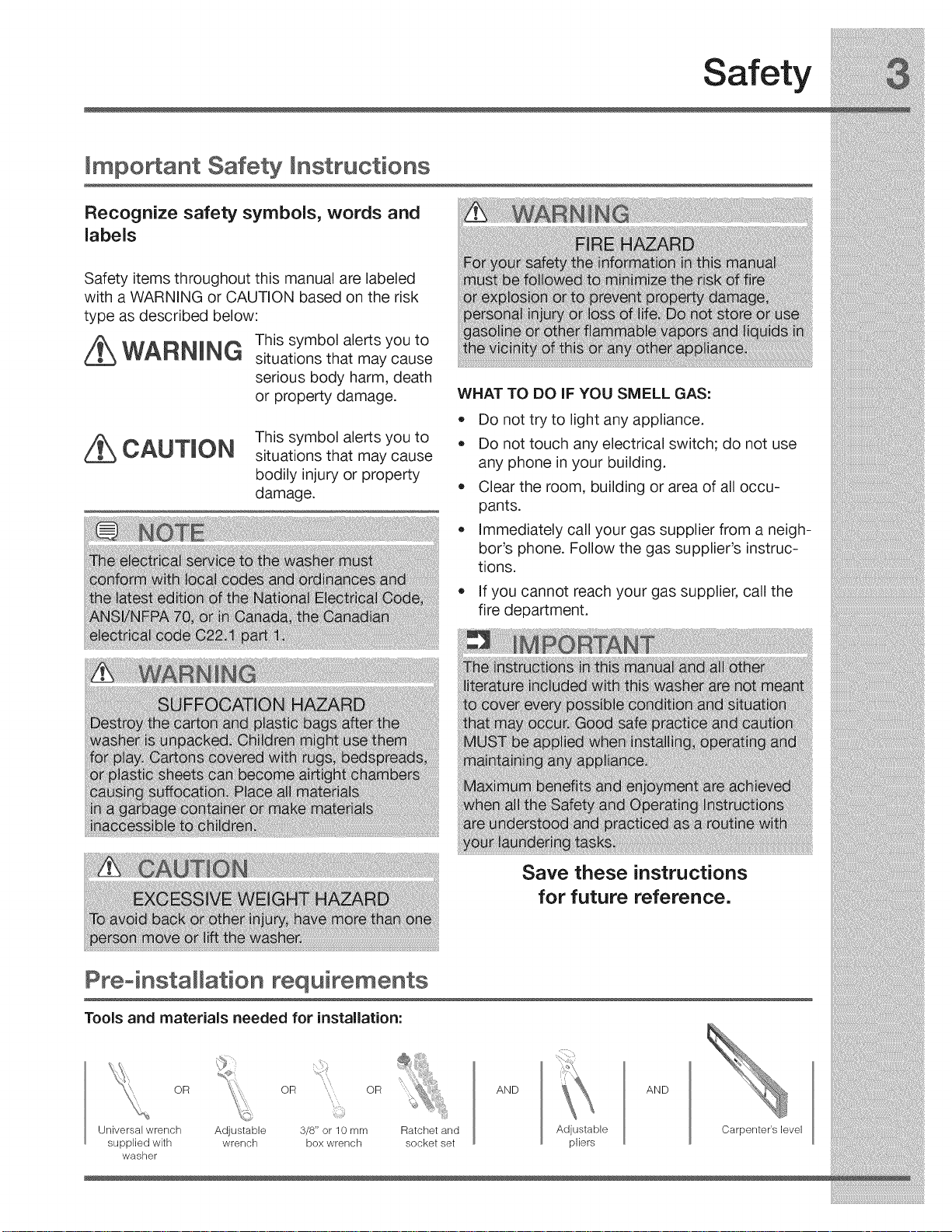
Preoinsta[[ation requirements
Tools and materials needed for installation:
OR OR OR
Universal wrench
supplied wkh
washer
Adjustable 3/8" or 10 mm
wrench box wrench
Ratchet and
socket set
Save these instructions
for future reference.
AND
Adjustable
plbrs
AND
Carpenter's level
Installation Requirements
E ectrica system requirements
CIRCUIT - Individual, properly polarized and
grounded 15 amp. branch circuit fused with 15
amp. time delay fuse or circuit breaker.
POWER SUPPLY - 2 wire, with ground, 120 volt
single phase, 60 Hz, Alternating Current.
supply cord having an equipment-grounding
conductor and a grounding plug, the plug
MUST be plugged into an appropriate, copper
wired receptacle that is properly installed and
grounded in accordance with all local codes and
ordinances or in the absence of local codes,
with the National Electrical Codes, ANSI/NFPA
70 (latest edition). If indoubt, call a licensed
electrician. DO NOT cut off or alter the grounding
prong on the power supply cord. In situations
where a two-slot receptacle is present, it is
the owner's responsibility to have a licensed
electrician replace it with a properly grounded
three prong grounding type receptacle.
OUTLET RECEPTACLE - Properly grounded
3-prong receptacle to be located so the power
supply cord is accessible when the washer is in
an installed position.
Groul
wall
Donot, under "_
anycircumstances, |
cut, remove, /
or bypassthe |
grounding prong, j)
Powercordwith
Grounding requirements
Water supply requirements
Hot and cold water faucets MUST be installed
within 42 inches (107 cm) of your washer's water
inlet. The faucets MUST be 3/4 inch (1.9 cm) with
threading for laundry hose connection. Water pres-
sure MUST be between 30 and 120 psi. Pressure
difference between hot and cold cannot be more
than 10 psi. Your water department can advise you
of your water pressure.
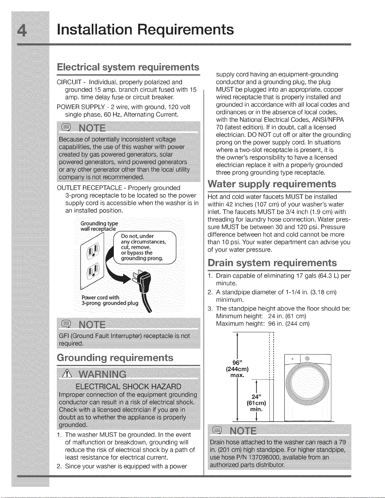
Drain system requirements
1. Drain capable of eliminating 17 gals (64.3 L) per
minute.
2. A standpipe diameter of 1-1/4 in. (3.18 cm)
minimum.
3. The standpipe height above the floor should be:
Minimum height: 24 in. (61 cm)
Maximum height: 96 in. (244 cm)
96 _
(244cm)
[lrlax.
1. The washer MUST be grounded. In the event
of malfunction or breakdown, grounding will
reduce the risk of electrical shock by a path of
least resistance for electrical current.
2. Since your washer is equipped with a power
(61 C/r I)
mln" m
Installation Requirements
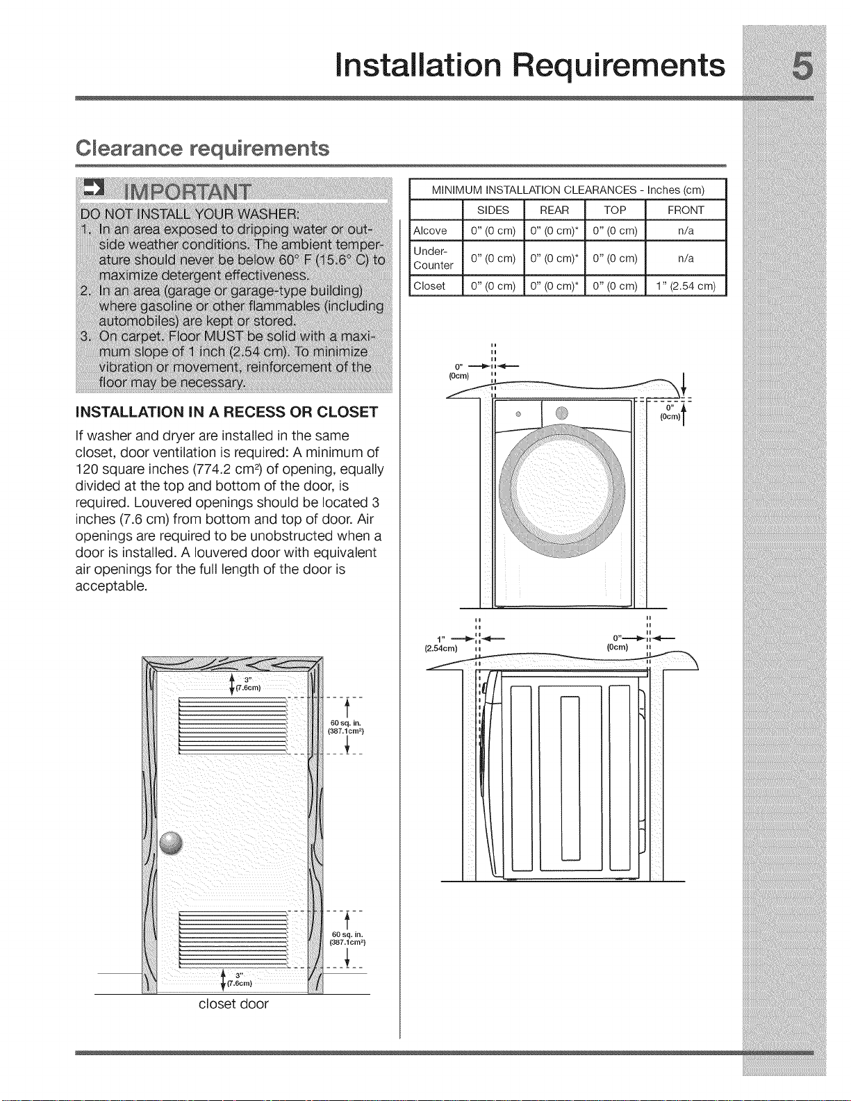
Clearance requirements
iNSTALLATiON iN A RECESS OR CLOSET
If washer and dryer are installed in the same
closet, door ventilation is required: A minimum of
120 square inches (774.2 cm 2)of opening, equally
divided at the top and bottom of the door, is
required. Louvered openings should be located 3
inches (7.6 cm) from bottom and top of door. Air
openings are required to be unobstructed when a
door is installed. A Iouvered door with equivalent
air openings for the full length of the door is
acceptable.
MINIMUM INSTALLATION CLEARANCES - Inches (cm)
SIDES REAR TOP FRONT
Alcove 0" (0 cm) 0" (0 cm)* 0" (0 cm) n/a
Under-
Counter 0" (0 cm) 0" (0 cm)* 0" (0 cm) n/a
Closet 0" (0 cm) 0" (0 cm)* 0" (0 cm) 1" (2.54 cm)
r(7.6crn]
closet door
lo O0
io II
H H
1" ""='€_ i i_ _=''= 0" -...........'li_i i_II,._
(2.54cm) i i (Ocrn} i i
i
installation Requirements
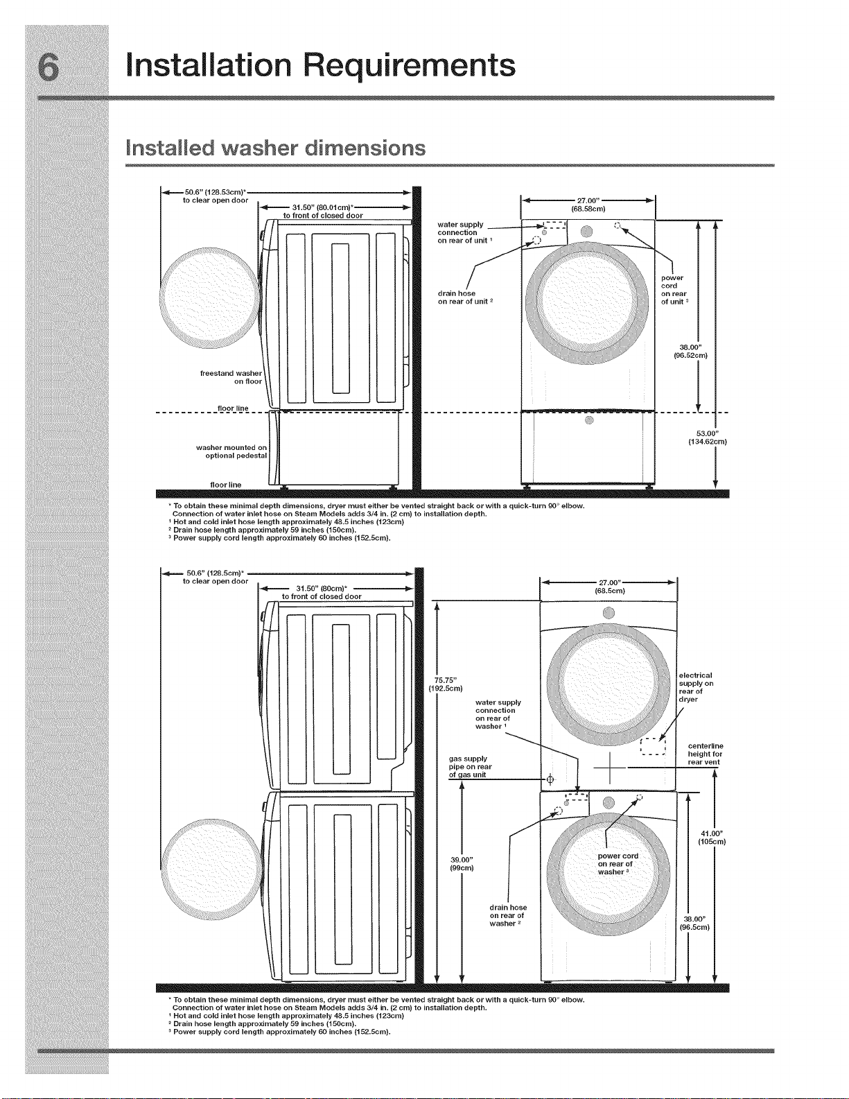
Installed washer dimensions
(128.53cm)*
to clear open door
freestand washer
floor line
washer mounted on
optional pedestal
on floor
(80.01cm)
to front of closed door
water supply
connection
on rear of unit 1
drain hose
on rear of unit 2
(68.58cm)
power
cord
on rear
of unit 3
(96.52cm)
38.00"
(134.62cm)
!
53.00"
floor line
* To obtain these minimal depth dimensions, dryer must either be vented straight back or with a quick-turn 90 ° elbow.
Connection of water inlet hose on Steam Models adds 3/4 in. (2 cm) to installation depth.
I Hot and cold inlet hose length approximately 48.5 inches (123cm)
2 Drain hose length approximately 59 inches (150cm).
3 Power supply cord length approximately 60 inches (152.5cm).
50.6" (128.5cm) _
to clear open door
31.50" (80cm)* --
to front of closed door
75.75"
(192.5cm)
water supply
connection
on rear of
washer 1
gas supply
pipe on rear
of gas unit
39.00"
(99cm)
!
drain hose
on rear of
washer 2
27.00
(68.5cm)
power cord
on rear of
electrical
supply on
rear of
dryer
centerline
height for
rear vent
(105cm)
41.00"
* To obtain these minimal depth dimensions, dryer must either be vented straight back or with a quick-turn 90 ° elbow.
Connection of water inlet hose on Steam Models adds 3/4 in. (2 cm) to installation depth.
I Hot and cold inlet hose length approximately 48.5 inches (123cm)
2 Drain hose length approximately 59 inches (150cm).
3 Power supply cord length approximately 50 inches (152.5cm).
 Loading...