

Electrolux EIGD55H, EIED55H, EWMGD65H, EWED65H, EWGDS65H Technical & Service Manual
...
DRYER SERVICE MANUAL #5995523544 2008 ALL RIGHTS RESERVED
WWaavvee--TToouucchh™™ && IIQQ--TToouucchh™™
FFrroonntt--LLooaadd DDrryyeerr
MMooddeellss
EEIIGGDD5555HH,, EEIIEEDD5555HH,, EEWWEEDD6655HH,, EEWWGGDDSS6655HH
EEWWMMEEDD6655HH && EEWWMMGGDD6655HH
TTeecchhnniiccaall SSeerrvviiccee MMaannuuaall


1-1
SSeeccttiioonn 11
BBaassiicc IInnffoorrmmaattiioonn
BBaassiicc IInnffoorrmmaattiioonn

BBaassiicc IInnffoorrmmaattiioonn
1-2
SSeeccttiioonn 11 -- BBaassiicc IInnffoorrmmaattiioonn
................................
11--11
Table of Contents.................................................... 1-2
Safe Servicing Practices ........................................ 1-4
Protect Children...................................................... 1-4
Prevent Fire ............................................................ 1-5
Product Specifications Wave-Touch™.................. 1-6
Product Specifications IQ-Touch™ ...................... 1-6
Serial Number Breakdown...................................... 1-6
Quick Reference Sheet .......................................... 1-7
Language of Laundry.............................................. 1-8
SSeeccttiioonn 22 -- IInnssttaallllaattiioonn IInnffoorrmmaattiioonn
................................................ 22--11
Important Safety Instructions ................................ 2-2
Safety Precautions.................................................. 2-2
Tools and Materials Needed for Installation .......... 2-3
Dryer Installation Dimensions ................................ 2-4
Exhaust System Requirements .............................. 2-5
Install Male Fittings in Correct Direction ................ 2-6
Exhaust Direction.................................................... 2-6
Manufactured or Mobile Home Installation ............ 2-6
Clearance Requirements ........................................ 2-7
Installation in a Recess or Closet .......................... 2-7
Electrical System Requirements ............................ 2-8
3-Wire Power Supply Cord Kit .............................. 2-8
4-Wire Power Supply Cord Kit .............................. 2-8
Outlet Receptacle .................................................. 2-8
Electrical Requirements for Gas Dryer .................. 2-8
Electrical Installation .............................................. 2-9
For a Grounded, Cord-connected Dryer:
(U.S.A. Electric Dryer) ............................................ 2-9
For a Grounded, Cord-connected Dryer:
(Canada Electric Dryer) .......................................... 2-9
Gas Dryer................................................................ 2-9
Electrical Connection (non-Canada) 3 Wire Cord .. 2-10
Electrical Connection (non-Canada) 4 Wire Cord .. 2-11
Gas Supply Requirements...................................... 2-12
Gas Connection ...................................................... 2-12
Water Connection (Steam Model Only).................. 2-13
General Installation ................................................ 2-14
Wave-Touch™ Installation Cycle ............................ 2-15
IQ -Touch™ Installation Cycle ................................ 2-15
Reversing Door ...................................................... 2-16
Preparing to Reverse Door Swing .......................... 2-16
Removing Trim Ring .............................................. 2-16
Removing Door from Hinge.................................... 2-16
Removing Hinge from Front Panel ........................ 2-17
Removing Door Lock from Front Panel.................. 2-17
Reattaching Door Lock to Font Panel .................... 2-18
Reattaching Hinge to Front Panel .......................... 2-18
Removing Striker Plate .......................................... 2-19
Removing Latch Indicator .................................... 2-19
Removing Hole Plug .............................................. 2-20
Reinserting Latch Indicator .................................... 2-20
Reattaching Striker Plate........................................ 2-21
Reinserting Hole Plug ............................................ 2-21
Reattaching Door Assembly .................................. 2-21
Reversing Trim Ring................................................ 2-22
Reinstalling Trim Ring ............................................ 2-22
Reinstalling Trim Plug ............................................ 2-22
Accessories ............................................................ 2-23
Matching Storage Pedestal .................................... 2-23
Dryer Stacking Kit .................................................. 2-23
Dryer Stacking Instructions .................................. 2-24
Kit Components...................................................... 2-24
Preparing to Stack.................................................. 2-24
Preparing Dryer for Stacking .................................. 2-24
Preparing Washer for Stacking .............................. 2-25
Prepare Top Surface of Washer ............................ 2-25
Stacking Dryer ........................................................ 2-25
Removing Stacked Dryer........................................ 2-26
SSeeccttiioonn 33 -- EElleeccttrroonniicc CCoonnttrrooll
................................................................ 33--11
Control Panel (User Interface Layout)
Wave-Touch™ ........................................................ 3-2
Selecting the Appropriate Cycle and Settings
Overview ................................................................ 3-2
Demo Mode ............................................................ 3-2
Wave-Touch™ Dryer Options Chart ...................... 3-3
Wave-Touch™ Dryer Options Chart
(Steam Model) ........................................................ 3-4
Control Panel (User Interface Layout)
IQ-Touch™ .............................................................. 3-5
Selecting the Appropriate Cycle and Settings
Overview ................................................................ 3-5
Demo Mode ............................................................ 3-5
IQ-Touch™ Dryer Options Chart ............................ 3-6
Cycle Selection ...................................................... 3-7
Auto Dry Cycles ................................................ 3-7
Normal .............................................................. 3-7
Towels................................................................ 3-7
Mixed Load........................................................ 3-8
Heavy Duty ........................................................ 3-8
Bulky/ Bedding.................................................. 3-8
Casual................................................................ 3-8
Active Wear ...................................................... 3-8
Delicate.............................................................. 3-8
Time Dry Cycles...................................................... 3-8
Time Dry ............................................................ 3-8
Fast Dry ............................................................ 3-8
Touch Up (non-steam models only) .................. 3-8
Perfect Steam (steam models only) .................. 3-8
My Favorites (Wave-Touch™) .......................... 3-9
Drying Temperature ................................................ 3-10
Auto Dry ............................................................ 3-10
Maximum Temp ................................................ 3-10
High Temp ........................................................ 3-10
Med High Temp ................................................ 3-10
Medium Temp.................................................... 3-10
Med Low Temp.................................................. 3-10
Low Temp .......................................................... 3-10
Air Fluff Temp .................................................... 3-10
Time Dry ............................................................ 3-10
Options .................................................................. 3-11
Add Steam (steam models only) ...................... 3-11
Extended Tumble .............................................. 3-11
Wrinkle Release (IQ-Touch™)............................ 3-11
Wrinkle Release (Wave-Touch™ ) .................... 3-11

1-3
SSeeccttiioonn 33 -- EElleeccttrroonniicc CCoonnttrrooll
Gentle Tumble .................................................. 3-12
Delicate Heat .................................................... 3-12
Sanitize .............................................................. 3-12
Chime ................................................................ 3-12
Delicate Heat .................................................... 3-12
Damp Alert ........................................................ 3-12
Shrink Guard .................................................... 3-12
User Interface Features .......................................... 3-13
Save as Favorite................................................ 3-13
Set Prefs............................................................ 3-13
User Guides ...................................................... 3-13
Stain Guides ...................................................... 3-13
Control Lock (Wave-Touch™) .......................... 3-13
Control Lock (IQ-Touch™) ................................ 3-13
My Favorites (Wave-Touch™) .......................... 3-13
Save as Favorite .................................................... 3-14
Setting Preferences ................................................ 3-15
Custom Mode.................................................... 3-15
Install Cycle (Wave-Touch™) ............................ 3-16
Install Cycle (IQ -Touch™) ................................ 3-16
Reset (Wave-Touch™) ...................................... 3-17
Reset (IQ-Touch™) ............................................ 3-17
Contrast ............................................................ 3-17
Brightness ........................................................ 3-18
Volume .............................................................. 3-18
Language .......................................................... 3-18
Cycle Description .............................................. 3-18
Status Display .................................................. 3-18
Drum Light ........................................................ 3-18
Diagnostics and Error Codes ................................ 3-19
Reading Error Codes .............................................. 3-19
To Clear Latest Stored Error Code ........................ 3-19
Exiting Diagnostic Mode ........................................ 3-19
Diagnostic Mode .................................................... 3-20
To Start the Diagnostic Mode ................................ 3-20
Error Code Chart .................................................... 3-21
IQ-Touch™ Available Cycle Settings, Pre-Sets
and Options Chart .................................................. 3-23
Wave-Touch™ Available Cycle Settings,
Pre-Sets and Options Chart .................................. 3-24
Wave-Touch™ with Steam, Available Cycle
Settings, Pre-Sets and Options Chart.................... 3-25
SSeeccttiioonn 44-- CCoommppoonneenntt TTeeaarrddoowwnn
.................................................... 44--11
Warnings and Cautions .......................................... 4-2
Door Components .................................................. 4-3
Door Trim Ring .................................................. 4-3
Door Assembly .................................................. 4-3
Latch Plate and Door Latch .............................. 4-4
Inner Door Glass .............................................. 4-4
Door Latch Assembly........................................ 4-4
Latch Indicator .................................................. 4-5
Door Strike ...................................................... 4-5
Outer Door Glass .............................................. 4-5
Door Hinge ........................................................ 4-6
Lint Trap .................................................................. 4-6
Air Duct Cover ........................................................ 4-6
Top Panel ................................................................ 4-7
Console and User Interface.................................... 4-7
Front Panel.............................................................. 4-8
Door Switch ............................................................ 4-8
Control Assembly .................................................. 4-9
Control Box Bracket .............................................. 4-9
Interior Light............................................................ 4-10
Top Rear Brace ...................................................... 4-10
Rear Panel .............................................................. 4-10
Inlet Thermistor ...................................................... 4-11
Moisture Sensing Bar ............................................ 4-11
Belt Removal (Wave Touch™) ................................ 4-12
Belt Removal (IQ Touch™)...................................... 4-12
Front Inner Panel and Drum .................................. 4-12
Roller Assembly ...................................................... 4-13
Front Air Duct ........................................................ 4-13
Exhaust Thermal Limiter ........................................ 4-14
Exhaust Tube .......................................................... 4-14
Outlet (Exhaust) Thermistor .................................. 4-14
Belt Tensioner (Wave Touch™) .............................. 4-15
Belt Tensioner (IQ Touch™) .................................. 4-15
Motor and Blower Assembly .................................. 4-16
Motor and Blower Assembly Separation................ 4-17
Drum Vane .............................................................. 4-18
Rear Heat Duct ...................................................... 4-18
Heat Shield ............................................................ 4-18
Electric Heater Function ........................................ 4-19
Heater Assembly .................................................... 4-19
Thermal Limiter and Safety Thermostat ................ 4-19
Gas Heater Assembly Breakdown.......................... 4-20
Thermal Limiters .................................................... 4-20
Gas Valve Wire Harness Connections.................... 4-20
Gas Valve Coil ........................................................ 4-20
Manifold and Burner Assembly Breakdown .......... 4-21
Combustion Tube .................................................. 4-22
SSeeccttiioonn 55-- TTrroouubblleesshhoooottiinngg
........................................................................ 55--11
Troubleshooting Chart ............................................ 5-2
Electrical Tests For Gas And Electric Dryers .......... 5-4
Electrical Tests For Electric Dryers ........................ 5-5
Electrical Tests For Gas Dryers .............................. 5-6
SSeeccttiioonn 66-- WWiirriinngg DDiiaaggrraammss
.................................................................... 66--11
Wiring Diagram Model EIED55H ............................ 6-2
Wiring Diagram Model EIGD55H ............................ 6-3
Wiring Diagram Model EWED65H .......................... 6-4
Wiring Diagram Model EWGD65H.......................... 6-5
Wiring Diagram Model EWMED65.......................... 6-6
Wiring Diagram Model EWMGD65 ........................ 6-7
BBaassiicc IInnffoorrmmaattiioonn

BBaassiicc IInnffoorrmmaattiioonn
1-4
SSaaffee SSeerrvviicciinngg PPrraaccttiicceess
AAvvooiidd ppeerrssoonnaall iinnjjuurryy aanndd//oorr pprrooppeerrttyy ddaammaaggee bbyy oobbsseerrvviinngg iimmppoorrttaanntt SSaaffee SSeerrvviicciinngg PPrraaccttiicceess..
FFoolllloowwiinngg aarree ssoommee lliimmiitteedd eexxaammpplleess ooff ssaaffee pprraaccttiicceess::
1. DO NOT attempt a product repair if you have any doubts as to your ability to complete the repair in a
safe and satisfactory manner.
2. Always Use The Correct Replacement Parts as indicated in the parts documentation. Substitutions
may defeat compliance with Safety Standards Set For Home Appliances.
3. Before servicing or moving an appliance:
• Remove power cord from the electrical outlet, trip circuit breaker to OFF position, or remove fuse.
• Turn off water supply for steam models.
• Turn off gas supply for gas dryers.
4. Never interfere with the proper operation of any safety device.
5. Use ONLY REPLACEMENT PARTS CATALOGED FOR THIS APPLIANCE. Substitutions may defeat
compliance with Safety Standards Set For Home Appliances.
6. GROUNDING: The standard color coding for safety ground wires is GREEN, or GREEN with YELLOW
STRIPES. Ground leads are not to be used as current carrying conductors.
It is EXTREMELY important that the service technician reestablish all safety grounds prior to
completion of service. Failure to do so will create a hazard.
7. Prior to returning the product to service, ensure that:
• All electrical connections are correct and secure.
• All electrical leads are properly dressed and secured away from sharp edges, high temperature
components, and moving parts.
• All non-insulated electrical terminals, connectors, heaters, etc. are adequately spaced away from all
metal parts and panels.
• All safety grounds (both internal and external) are correctly and securely connected.
• All panels are properly and securely reassembled
• Gas and water supplies are turned ON if shut off prior to service.
PPrrootteecctt CChhiillddrreenn
Do not allow children to play on or in the dryer.Close supervision of children is necessary when the dryer
is used near children. As children grow, teach them the proper, safe use of all appliances.
Destroy the carton, plastic bag and other packing materials after the dryer is unpacked.
Children might use them for play. Cartons covered with rugs, bedspreads or plastic sheets can become
airtight chambers.
Keep laundry products out of children’s reach. To prevent personal injury, observe all warnings on product
labels.
Before the dryer is removed from service or discarded, remove the dryer door to prevent accidental
entrapment.
Failure to comply with these warnings could result in serious personal injuries.
TThhiiss sseerrvviiccee mmaannuuaall iiss iinntteennddeedd ffoorr uussee bbyy ppeerrssoonnss hhaavviinngg eelleeccttrriiccaall aanndd mmeecchhaanniiccaall ttrraaiinniinngg aanndd aa
lleevveell ooff kknnoowwlleeddggee ooff tthheessee ssuubbjjeeccttss ggeenneerraallllyy ccoonnssiiddeerreedd aacccceeppttaabbllee iinn tthhee aapppplliiaannccee rreeppaaiirr ttrraaddee..
EElleeccttrroolluuxx HHoommee PPrroodduuccttss,, IInncc.. ccaannnnoott bbee rreessppoonnssiibbllee,, nnoorr aassssuummee aannyy lliiaabbiilliittyy,, ffoorr iinnjjuurryy oorr ddaammaaggee ooff
aannyy kkiinndd aarriissiinngg ffrroomm tthhee uussee ooff tthhiiss mmaannuuaall..

BBaassiicc IInnffoorrmmaattiioonn
1-5
PPrreevveenntt FFiirree
Do not dry items that have been previously cleaned in, soaked in, or spotted with gasoline, cleaning
solvents, kerosene, waxes, etc. Do not store these items on or near the dryer. These substances give off
vapors that could ignite or explode.
Do not place items exposed to cooking oils in your dryer. Items contaminated with cooking oils may
contribute to a chemical reaction that could cause a load to catch fire.
To prevent fire, do not use heat to dry items containing plastic, foam rubber or similarly textured rubberlike materials, or items containing feathers or down. Use Air Fluff (No Heat) only.
Clean the lint screen before or after each load. The interior of the dryer, lint screen housing and exhaust
duct should be cleaned approximately every 18 months by qualified service personnel. An excessive
amount of lint buildup in these areas could result in inefficient drying and possible fire.
Do not operate the dryer if the lint screen is blocked, damaged or missing. Fire hazard, overheating and
damage to fabrics can occur. If your dryer has a drying rack, always replace the lint screen when finished
using the drying rack.
Keep area around exhaust opening and surrounding areas free from the accumulation of lint, dust and dirt.
Do not obstruct the flow of ventilating air. Do not stack or place laundry or throw rugs against the front or
back of the dryer.
Do not spray any type of aerosol into, on or near dryer at any time.
Do not use fabric softeners or products to eliminate static unless recommended by the manufacturer of
the fabric softener or product.
Failure to comply with these warnings could result in fire, explosion, serious bodily injury and/or damage
to the rubber or plastic parts of the dryer.
TTOO PPRREEVVEENNTT PPEERRSSOONNAALL IINNJJUURRYY OORR DDAAMMAAGGEE TTOO TTHHEE DDRRYYEERR,, TTHHEE EELLEECCTTRRIICCAALL PPOOWWEERR CCOORRDD
OOFF AA GGAASS DDRRYYEERR MMUUSSTT BBEE PPLLUUGGGGEEDD IINNTTOO AA PPRROOPPEERRLLYY GGRROOUUNNDDEEDD AANNDD PPOOLLAARRIIZZEEDD 33--PPRROONNGG
OOUUTTLLEETT.. TTHHEE TTHHIIRRDD GGRROOUUNNDDIINNGG PPRROONNGG MMUUSSTT NNEEVVEERR BBEE RREEMMOOVVEEDD..
NNEEVVEERR GGRROOUUNNDD TTHHEE DDRRYYEERR TTOO AA GGAASS PPIIPPEE..
DDOO NNOOTT UUSSEE AANN EEXXTTEENNSSIIOONN CCOORRDD OORR AANN AADDAAPPTTEERR PPLLUUGG..
AALLWWAAYYSS DDIISSCCOONNNNEECCTT TTHHEE DDRRYYEERR FFRROOMM TTHHEE EELLEECCTTRRIICCAALL SSUUPPPPLLYY BBEEFFOORREE AATTTTEEMMPPTTIINNGG AANNYY
SSEERRVVIICCEE OORR CCLLEEAANNIINNGG.. FFAAIILLUURREE TTOO DDOO SSOO CCAANN RREESSUULLTT IINN EELLEECCTTRRIICCAALL SSHHOOCCKK OORR IINNJJUURRYY..
DDOO NNOOTT UUSSEE AANNYY TTYYPPEE SSPPRRAAYY CCLLEEAANNSSEERR WWHHEENN CCLLEEAANNIINNGG DDRRYYEERR IINNTTEERRIIOORR.. HHAAZZAARRDDOOUUSS
FFUUMMEESS OORR EELLEECCTTRRIICCAALL SSHHOOCCKK CCOOUULLDD OOCCCCUURR..
TTOO PPRREEVVEENNTT IINNJJUURRYY,, DDOO NNOOTT RREEAACCHH IINNTTOO TTHHEE DDRRYYEERR IIFF TTHHEE DDRRUUMM IISS MMOOVVIINNGG.. WWAAIITT UUNNTTIILL
TTHHEE DDRRYYEERR HHAASS SSTTOOPPPPEEDD CCOOMMPPLLEETTEELLYY BBEEFFOORREE RREEAACCHHIINNGG IINNTTOO TTHHEE DDRRUUMM..
TTOO PPRREEVVEENNTT IINNJJUURRYY AANNDD DDAAMMAAGGEE TTOO TTHHEE DDRRYYEERR::
•• AALLLL RREEPPAAIIRRSS AANNDD SSEERRVVIICCIINNGG MMUUSSTT BBEE PPEERRFFOORRMMEEDD BBYY AANN AAUUTTHHOORRIIZZEEDD SSEERRVVIICCEERR
UUNNLLEESSSS SSPPEECCIIFFIICCAALLLLYY RREECCOOMMMMEENNDDEEDD IINN TTHHIISS OOWWNNEERR’’SS GGUUIIDDEE..
UUSSEE OONNLLYY AAUUTTHHOORRIIZZEEDD FFAACCTTOORRYY PPAARRTTSS..
•• DDOO NNOOTT TTAAMMPPEERR WWIITTHH CCOONNTTRROOLLSS..
•• DDOO NNOOTT IINNSSTTAALLLL OORR SSTTOORREE TTHHEE DDRRYYEERR WWHHEERREE IITT WWIILLLL BBEE EEXXPPOOSSEEDD TTOO TTHHEE
WWEEAATTHHEERR..

BBaassiicc IInnffoorrmmaattiioonn
1-6
PPrroodduucctt SSppeecciiffiiccaattiioonnss WWaavvee TToouucchh
™
DDrryyeerr
2 Premium Colors
Enhanced LCD Controls (with larger trilingual display)
Reversing Drum
Quiet (56 dBA maximum)
11 Standard and 3 Favorite Cycles with custom
settings to reach 42 Total Cycles
Multiple User Mode – 3 User Modes with Favorite
and Custom Cycles
8 Timed Dry Options
Shrink Guard
Drum Light with manual switch
2 Temperature Selections (7 total)
Steam
Fastest Cycle Time
CCyycclleess
NSF Certified
Heavy Duty
Bulky/Bedding
Mixed Load
Towels
Normal
Active Wear – Use for sports/workout gear
Quick Dry – The fastest cycle in the industry
Casual – Use for Permanent Press items
Delicate – Gentler than any cycle available
Touch Up
Time Dry – Up to 90 minutes
My Favorite – Programmable by consumer
AAddddiittiioonnaall OOppttiioonnss
Damp Alert – For items that will be ironed.
Control Lock – to prevent accidental operation by
children
7 Temperature Selections
Wrinkle Rid – Extends tumble time so wrinkles do
not set.
Soft Heat – Reduces the temperature as the cycle
progresses to prevent damage.
PPrroodduucctt SSppeecciiffiiccaattiioonnss IIQQ TToouucchh™DDrryyeerr
White and 1 Premium Color
Superior drying – Even & Gentle
Reversible Door
Push2Open: Door & Pedestal
Large Capacity (8 cu. ft.)
Intelligent and Adaptive LCD Controls
Electrolux Blue LEDs
Custom Cycles Including My Favorite
Quiet (59 dBA maximum)
Top CU Rating
11 Cycles with 4 Dryness levels and 5
Temperature Selections
NSF Rated Sanitary Cycle
Fastest Cycle Time
CCyycclleess
NSF Certified
Heavy Duty
Bulky/Bedding
Mixed Load
Towels
Normal
Quick Dry – The fastest cycle in the industry
Casual – Use for Permanent Press items
Delicate – Gentler than any cycle available
Touch Up
Time Dry – Up to 90 minutes
My Favorite – Programmable by consumer
AAddddiittiioonnaall OOppttiioonnss
Damp Alert – For items that will be ironed.
Control Lock – to prevent accidental operation by
children
5 Temperature Selections
Wrinkle Rid – Extends tumble time so wrinkles do
not set.
Soft Heat – Reduces the temperature as the cycle
progresses to prevent damage.
MMooddeell NNuummbbeerr BBrreeaakkddoowwnn
Each model follows the following nomenclature:
E ..................for Electrolux
I ..................for IQ Touch
W ..................for Wave Touch
FLW ..............for Front Load Washer
ED ................for Electric Dryer
GD ................for Gas Dryer
MED/MGD ....Steam Electric/Steam Gas Dryer
P ....................for Pedestal
SSeerriiaall NNuummbbeerr BBrreeaakkddoowwnn
Serial Number Breakdown
4D82812345
Production Week
Last Digit of Production Year
Product Identication
Manufacturing Facility
Incremented unit number

BBaassiicc IInnffoorrmmaattiioonn
1-7
QUICK REFERENCE SHEET
SPECIFICATION
Electrical
Vol ts 120/208 or 120/240
Amps (circuit)
Motor wattage
Heat input (Watts @ 240 VAC)
Heat input (BTU/Hr.)
Auto. Elec. Ignition
Drum
Size (Cu. Ft.)
Finish
R.P.M.
Airow CFM
DRUM TEMPERATURES
(Max. opening on 3rd cycle)
Maximum
Medium
Low
Dimension (Inches)
Height
Width
Depth
ELECTRIC MODELS
120/208 or 120/240
30
200-290 Watts
4300/5500
---
---
8.0
Powder Paint Epoxy
48 - 54
200
120° - 160°
110° - 140°
95° - 130°
38”
27”
31.5”
GAS MODELS
120
15
200-290 Watts
---
22,000
Ye s
8.0
Powder Paint Epoxy
48 - 54
200
120° - 180°
105° - 145°
95° - 130°
38”
27”
31.5”
Vent Capability
Top Finish
Port Opening (Sq.In.)
Component Resistances*
Drive motor (120 volt, 60 Hz, 1/4 h.p. 1725 rpm)
Motor Start Winding
Motor Run Winding
Heating Element
Control Thermistor
Burner Assembly
Ignitor
Secondary Coil
Booster Coil
Powder Paint Enamel
4-Way
235
Electric Models
4.5 Ohms
3.8 Ohms
26.4 Ohms
50K Ohms
+/- 5% @ 77° F
---
---
---
4-Way
Powder Paint Enamel
235
Gas Models
4.5 Ohms
3.8 Ohms
50K Ohms
+/- 5% @ 77° F
50 - 400 Ohms
1200 Ohms
1320 Ohms
* +/- 10% @ 77° F

BBaassiicc IInnffoorrmmaattiioonn
1-8
The Language of Laundry
Machine Wash
Instructions
Normal
Wash
Permanent
Press
Gentle
Cycle
DO NOT
Machine Wash
Cold
(<85ºF)
Special
Care
Hand
Wash
DO NOT
Wring
Bleaching
Instructions
Bleach
as Needed
Non-chlorine
Bleach as Needed
DO NOT
Bleach
Instructions
Normal
Dry
Permanent
Press
Gentle
Setting
DO NOT
Tumble Dry
No Heat
Dryer
Machine Dry
DO NOT
Line Dry
Drip Dry
Dry Flat
Dry in
Shade
Ironing
Instructions
Low Heat
Med. Heat
High Heat
DO NOT
Steam
DO NOT
Iron
Dry
Cleaning
Dry Clean
Dry Clean
w/ Any
Solvent
Dry Clean
w/Petroleum
Solvent
Dry Clean
w/Solvents
Other Than
Trichloroethylene
DO NOT
Dry Clean
Warm
(<105ºF)
Hot
(<120ºF)
Hot
(<140ºF)
Low Heat
Normal/
Med. Heat
High
Heat

IInnssttaallllaattiioonn IInnffoorrmmaattiioonn
2-1
SSeeccttiioonn 22
IInnssttaallllaattiioonn IInnffoorrmmaattiioonn

IInnssttaallllaattiioonn IInnffoorrmmaattiioonn
2-2
IIMMPPOORRTTAANNTT SSAAFFEETTYY IINNSSTTRRUUCCTTIIOONNSS
SSaaffeettyy PPrreeccaauuttiioonnss
Do not attempt to install or operate this appliance until you read the safety precautions in this guide.
Safety items throughout this guide are labeled with a Warning or Caution based on the risk type.
WWAARRNNIINNGG
indicates a potentially hazardous situation which, if not avoided, could result in death or
serious injury.
CCaauuttiioonn
indicates a potentially hazardous situation which, if not avoided, may result in minor or
moderate injury.
EELLEECCTTRROOLLUUXX CCAANNNNOOTT BBEE HHEELLDD RREESSPPOONNSSIIBBLLEE FFOORR DDAAMMAAGGEE TTOO PPRROOPPEERRTTYY OORR IINNJJUURRYY TTOO
PPEERRSSOONNSS CCAAUUSSEEDD BBYY FFAAIILLUURREE TTOO CCOOMMPPLLYY WWIITTHH TTHHEE IINNSSTTAALLLLAATTIIOONN,, MMAAIINNTTEENNAANNCCEE AANNDD
SSAAFFEETTYY IINNSSTTRRUUCCTTIIOONNSS CCOONNTTAAIINNEEDD IINN TTHHIISS SSEERRVVIICCEE MMAANNUUAALL..
TTOO RREEDDUUCCEE TTHHEE RRIISSKK OOFF FFIIRREE,, EELLEECCTTRRIICCAALL SSHHOOCCKK,, OORR IINNJJUURRYY WWHHEENN UUSSIINNGG AA
WWAAVVEE--TTOOUUCCHH™™ OORR IIQQ--TTOOUUCCHH™™ DDRRYYEERR,, FFOOLLLLOOWW BBAASSIICC SSAAFFEETTYY PPRREECCAAUUTTIIOONNSS IINNCCLLUUDDIINNGG
TTHHEE FFOOLLLLOOWWIINNGG::
-- RREEAADD AALLLL IINNSSTTRRUUCCTTIIOONNSS BBEEFFOORREE OOPPEERRAATTIINNGG TTHHEE DDRRYYEERR..
-- BBEEFFOORREE PPEERRFFOORRMMIINNGG AANNYY TTYYPPEE OOFF SSEERRVVIICCEE OORR IINNSSTTAALLLLAATTIIOONN,, MMAAKKEE SSUURREE TTHHAATT
EELLEECCTTRRIICC PPOOWWEERR TTOO TTHHEE DDRRYYEERR IISS DDIISSCCOONNNNEECCTTEEDD..
-- TTOO AAVVOOIIDD TTHHEE PPOOSSSSIIBBIILLIITTYY OOFF EEXXPPLLOOSSIIOONN OORR FFIIRREE,, DDOO NNOOTT SSTTOORREE OORR UUSSEE
CCOOMMBBUUSSTTIIBBLLEE,, FFLLAAMMMMAABBLLEE,, OORR EEXXPPLLOOSSIIVVEE LLIIQQUUIIDDSS OORR VVAAPPOORRSS ((SSUUCCHH AASS GGAASSOOLLIINNEE))
IINNSSIIDDEE OORR IINN TTHHEE VVIICCIINNIITTYY OOFF TTHHIISS OORR AANNYY OOTTHHEERR AAPPPPLLIIAANNCCEE..
-- TTHHIISS AAPPPPLLIIAANNCCEE IISS EEQQUUIIPPPPEEDD WWIITTHH AA TTHHRREEEE--PPRROONNGG GGRROOUUNNDDIINNGG PPLLUUGG FFOORR
PPRROOTTEECCTTIIOONN AAGGAAIINNSSTT PPOOSSSSIIBBLLEE EELLEECCTTRRIICC SSHHOOCCKK HHAAZZAARRDDSS.. PPLLUUGG IITT OONNLLYY IINNTTOO AA
DDEEDDIICCAATTEEDD,, GGRROOUUNNDDEEDD EELLEECCTTRRIICCAALL OOUUTTLLEETT.. WWHHEENN OONNLLYY AA SSTTAANNDDAARRDD TTWWOO--PPRROONNGG
EELLEECCTTRRIICCAALL OOUUTTLLEETT IISS AAVVAAIILLAABBLLEE,, TTHHEE CCUUSSTTOOMMEERR MMUUSSTT HHAAVVEE IITT RREEPPLLAACCEEDD WWIITTHH AA
DDEEDDIICCAATTEEDD,, PPRROOPPEERRLLYY GGRROOUUNNDDEEDD TTHHRREEEE--PPRROONNGG EELLEECCTTRRIICCAALL OOUUTTLLEETT BBEEFFOORREE UUSSIINNGG
TTHHIISS AAPPPPLLIIAANNCCEE.. DDOO NNOOTT UUNNDDEERR AANNYY CCIIRRCCUUMMSSTTAANNCCEESS,, CCUUTT OORR RREEMMOOVVEE TTHHEE TTHHIIRRDD
((GGRROOUUNNDD)) PPRROONNGG FFRROOMM TTHHEE PPOOWWEERR CCOORRDD.. DDOO NNOOTT UUSSEE AANN AADDAAPPTTEERR PPLLUUGG.. DDOO NNOOTT
UUSSEE AANN EEXXTTEENNSSIIOONN CCOORRDD.. DDOO NNOOTT UUSSEE AA PPOOWWEERR CCOORRDD TTHHAATT IISS FFRRAAYYEEDD OORR DDAAMMAAGGEEDD..
TTHHEE UUSSEE OOFF AA GGRROOUUNNDD FFAAUULLTT IINNTTEERRRRUUPPTTEERR ((GGFFII)) IISS NNOOTT RREECCOOMMMMEENNDDEEDD..
-- DDOO NNOOTT IINNSSTTAALLLL OORR UUSSEE AA DDAAMMAAGGEEDD AAPPPPLLIIAANNCCEE.. IIFF YYOOUU RREECCEEIIVVEE AA DDAAMMAAGGEEDD
AAPPPPLLIIAANNCCEE,, IIMMMMEEDDIIAATTEELLYY CCOONNTTAACCTT YYOOUURR DDEEAALLEERR OORR BBUUIILLDDEERR..
-- DDOO NNOOTT UUSSEE TTHHEE DDRRYYEERR UUNNTTIILL IITT HHAASS BBEEEENN PPRROOPPEERRLLYY IINNSSTTAALLLLEEDD BBYY AA QQUUAALLIIFFIIEEDD
IINNSSTTAALLLLEERR AACCCCOORRDDIINNGG TTOO TTHHEESSEE IINNSSTTAALLLLAATTIIOONN IINNSSTTRRUUCCTTIIOONNSS.. TTHHEE IINNSSTTAALLLLEERR MMUUSSTT
SSHHOOWW TTHHEE CCUUSSTTOOMMEERR TTHHEE LLOOCCAATTIIOONN OOFF TTHHEE PPOOWWEERR PPLLUUGG SSOO TTHHAATT TTHHEEYY KKNNOOWW WWHHEERREE
AANNDD HHOOWW TTOO DDIISSCCOONNNNEECCTT PPOOWWEERR TTOO TTHHEE DDRRYYEERR..
-- DDOO NNOOTT IINNSSTTAALLLL,, RREEPPAAIIRR,, OORR RREEPPLLAACCEE AANNYY PPAARRTT OOFF TTHHEE DDRRYYEERR UUNNLLEESSSS
SSPPEECCIIFFIICCAALLLLYY RREECCOOMMMMEENNDDEEDD IINN TTHHEE LLIITTEERRAATTUURREE AACCCCOOMMPPAANNYYIINNGG IITT.. AA QQUUAALLIIFFIIEEDD
SSEERRVVIICCEE TTEECCHHNNIICCIIAANN SSHHOOUULLDD PPEERRFFOORRMM AALLLL OOTTHHEERR SSEERRVVIICCEE..
IInnssttaallllaattiioonn IInnffoorrmmaattiioonn
2-3
WWHHAATT TTOO DDOO IIFF YYOOUU SSMMEELLLL GGAASS::
•• DDoo nnoott ttrryy ttoo lliigghhtt aannyy aapppplliiaannccee..
•• DDoo nnoott ttoouucchh aannyy eelleeccttrriiccaall sswwiittcchh;; ddoo nnoott uussee aannyy pphhoonnee iinn yyoouurr bbuuiillddiinngg..
•• CClleeaarr tthhee rroooomm,, bbuuiillddiinngg oorr aarreeaa ooff aallll ooccccuuppaannttss..
•• IImmmmeeddiiaatteellyy ccaallll yyoouurr ggaass ssuupppplliieerr ffrroomm aa nneeiigghhbboorr’’ss pphhoonnee.. FFoollllooww tthhee ggaass ssuupppplliieerr’’ss iinnssttrruuccttiioonnss..
•• IIff yyoouu ccaannnnoott rreeaacchh yyoouurr ggaass ssuupppplliieerr,, ccaallll tthhee ffiirree ddeeppaarrttmmeenntt..
PPrree--iinnssttaallllaattiioonn RReeqquuiirreemmeennttss
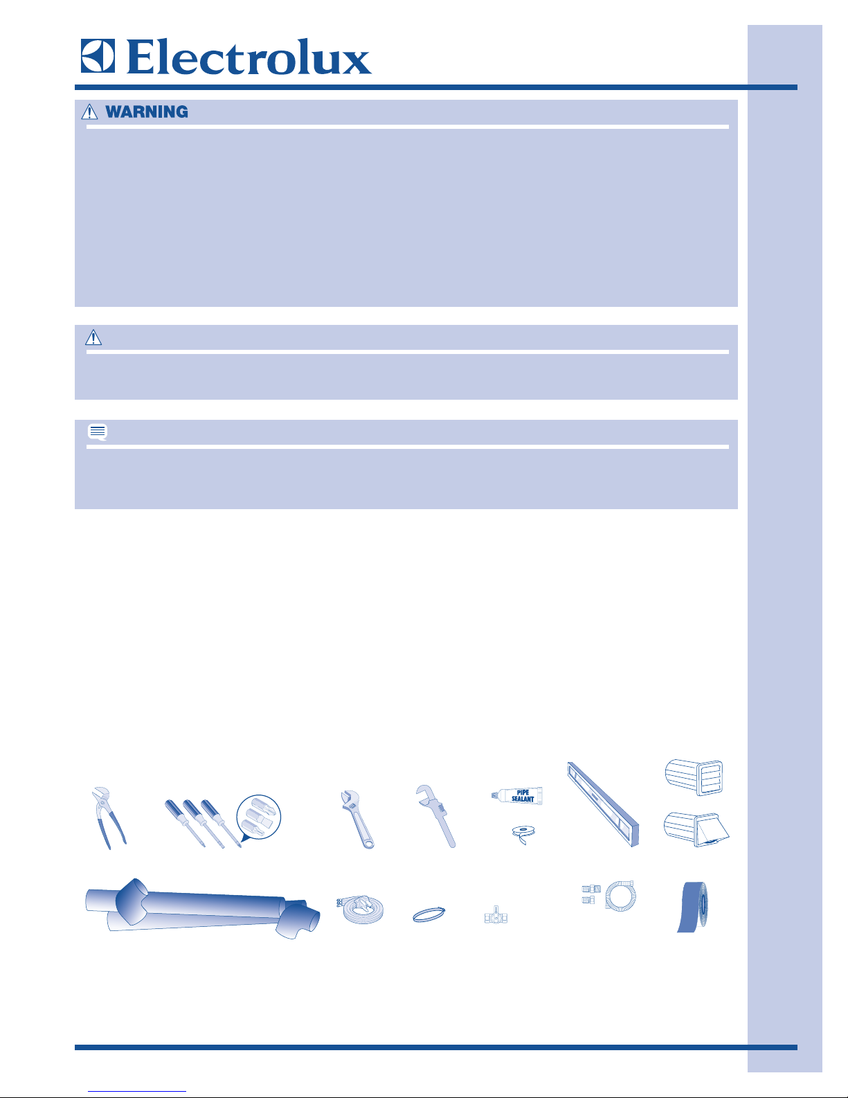
TToooollss aanndd mmaatteerriiaallss nneeeeddeedd ffoorr iinnssttaallllaattiioonn::
DDEESSTTRROOYY CCAARRTTOONN,, PPLLAASSTTIICC BBAAGGSS,, AANNDD AANNYY EEXXTTEERRIIOORR WWRRAAPPPPIINNGG MMAATTEERRIIAALL IIMMMMEEDDIIAATTEELLYY
AAFFTTEERR TTHHEE DDRRYYEERR IISS UUNNPPAACCKKEEDD.. CCHHIILLDDRREENN SSHHOOUULLDD NNEEVVEERR UUSSEE TTHHEESSEE IITTEEMMSS FFOORR PPLLAAYY..
CCAARRTTOONNSS CCOOVVEERREEDD WWIITTHH RRUUGGSS,, BBEEDDSSPPRREEAADDSS,, PPLLAASSTTIICC SSHHEEEETTSS OORR SSTTRREETTCCHH WWRRAAPP MMAAYY
BBEECCOOMMEE AAIIRR TTIIGGHHTT CCHHAAMMBBEERRSS AANNDD CCAANN QQUUIICCKKLLYY CCAAUUSSEE SSUUFFFFOOCCAATTIIOONN..
KKEEEEPP LLAAUUNNDDRRYY PPRROODDUUCCTTSS OOUUTT OOFF CCHHIILLDDRREENN’’SS RREEAACCHH.. TTOO PPRREEVVEENNTT PPEERRSSOONNAALL IINNJJUURRYY,,
OOBBSSEERRVVEE AALLLL WWAARRNNIINNGGSS OONN PPRROODDUUCCTT LLAABBEELLSS..
CCUUTT HHAAZZAARRDD.. TTOO PPRREEVVEENNTT SSEERRIIOOUUSS IINNJJUURRYY FFRROOMM SSHHAARRPP EEDDGGEESS,, WWEEAARR WWOORRKK GGLLOOVVEESS
WWHHEENN HHAANNDDLLIINNGG,, UUNNPPAACCKKIINNGG OORR DDIISSAASSSSEEMMBBLLIINNGG UUNNIITT..
EEXXCCEESSSSIIVVEE WWEEIIGGHHTT HHAAZZAARRDD
TToo aavvooiidd bbaacckk oorr ootthheerr iinnjjuurryy,, hhaavvee mmoorree tthhaann oonnee ppeerrssoonn mmoovvee oorr lliifftt tthhee ddrryyeerr..
TThhee eelleeccttrriiccaall sseerrvviiccee ttoo tthhee ddrryyeerr mmuusstt ccoonnffoorrmm wwiitthh llooccaall ccooddeess aanndd oorrddiinnaanncceess aanndd tthhee llaatteesstt
eeddiittiioonn ooff tthhee NNaattiioonnaall EElleeccttrriiccaall CCooddee,, AANNSSII//NNFFPPAA 7700,, oorr iinn CCaannaaddaa,, tthhee CCaannaaddiiaann eelleeccttrriiccaall ccooddee
CC2222..11 ppaarrtt 11..
CAUTION
NOTE
or
Adjustable
pliers
semi-rigid metal exhaust duct work
Phillips, straight, &
square bit screwdrivers
4 inch, rigid metal or
Adjustable
wrench
3-wire or 4-wire
240 volt cord kit
(electric dr yer)
Pipe wrench
for gas
supply
4 in.
(10.2 cm)
clamp
LP-resistant
thread tape
(for natural gas
or LP supply)
gas line
shutoff valve
(gas dr yer)
Carpenter’s level
½” NPT union are
adapters (x2) and
exible gas supply line
(gas dr yer)
External
vent hood
Metal foil tape
(not duct tape)
or
IInnssttaallllaattiioonn IInnffoorrmmaattiioonn
2-4
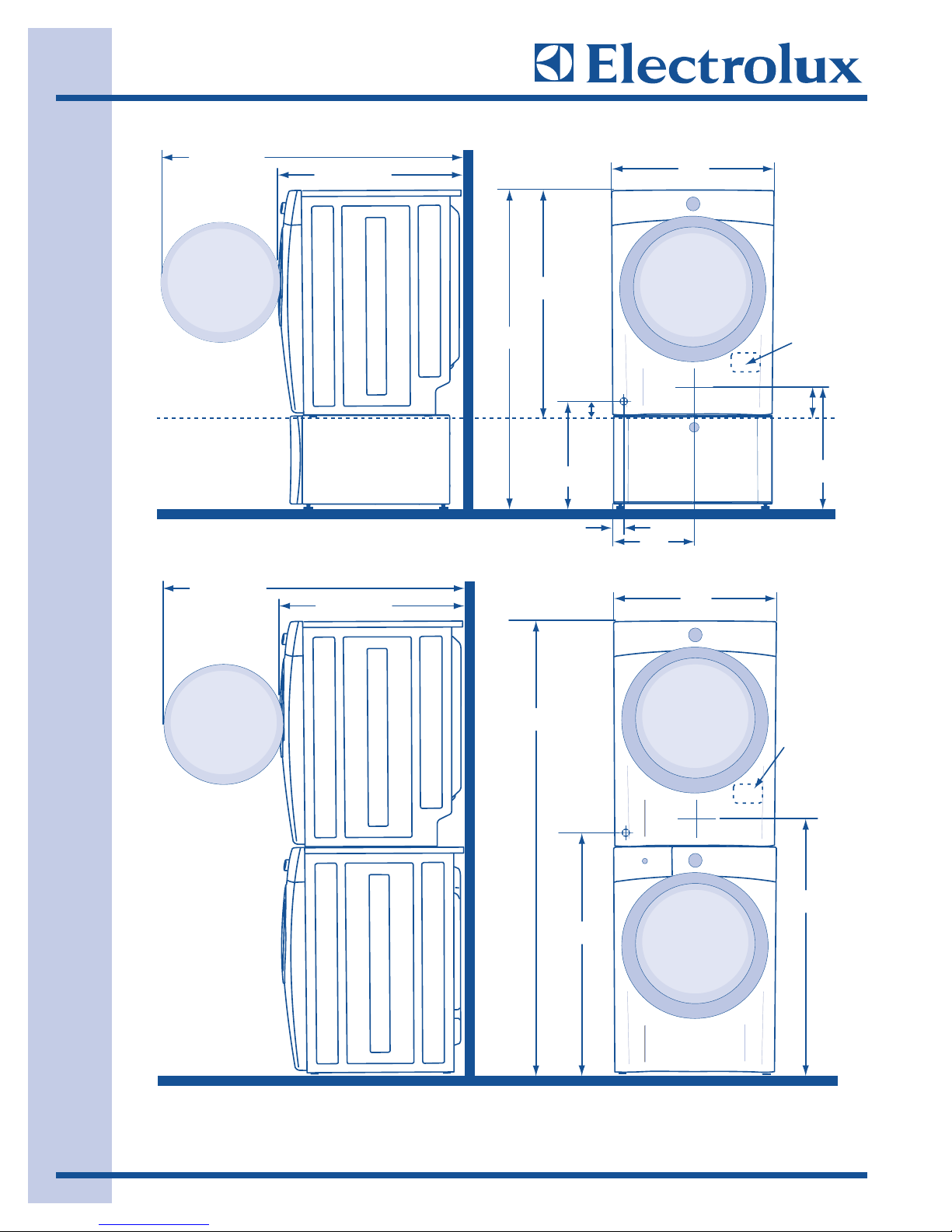
DDrryyeerr IInnssttaallllaattiioonn DDiimmeennssiioonnss
FFiigguurree 22--11..
50.6” (128.5cm)*
To clear open door
Freestand dryer
on oor
Floor line
31.50” (80cm)*
To front of closed door
53.00”
(134.5cm)
38.00”
(96.5cm)
Gas supply
pipe on rear
of gas unit
1.4”
(3.5cm)
27.00”
(68.5cm)
Electrical
supply on
rear of unit
Centerline
height for
rear vent
3.40”
(8.5cm)
Dryer mounted on
optional pedestal
Floor line
* To obtain these minimal depth dimensions, dryer must either be vented straight back
or with a quick-turn90° elbow. Connection of water inlet hose on Steam Models
adds 3/4 in. (2 cm) to installation depth.
50.6” (128.5cm)*
To clear open door
31.50” (80cm)*
To front of closed door
75.75”
(192.5cm)
16.25”
(41.5cm)
3.75”
(9.5cm)
Gas supply
pipe on rear
of gas unit
39.00”
(99cm)
13.50”
(34.5cm)
To center of rear vent
27.00”
(68.5cm)
18.25”
(46.5cm)
Electrical
supply on
rear of unit
Centerline
height for
rear vent
41.00”
(104cm)
* To obtain these minimal depth dimensions, dryer must either be vented straight back or with a quick-turn 90° elbow.
Connection of water inlet hose on Steam Models adds 3/4 in. (2 cm) to installation depth.
IInnssttaallllaattiioonn IInnffoorrmmaattiioonn
2-5
EExxhhaauusstt SSyysstteemm RReeqquuiirreemmeennttss
Use only 4 inch (10.2 cm) diameter (minimum) rigid
or flexible metal duct and approved vent hood
which has a swing-out damper(s) that open when
the dryer is in operation. When the dryer stops,
the dampers automatically close to prevent drafts
and the entrance of insects and rodents. To avoid
restricting the outlet, maintain a minimum of 12
inches (30.5 cm) clearance between the vent hood
and the ground or any other obstruction.
If the present system is made up of plastic duct or
metal foil duct, replace it with a rigid or semi-rigid
metal duct. In Canada and the United States if
metal (foil type) duct is installed, it must be of a
specific type identified by the appliance manufacturer as suitable for use with clothes dryers and in
the United States must also comply with the
Outline for Clothes Dryer Transition Duct, UL
standard 2158A. Also, ensure the present duct is
free of any lint prior to installing dryer duct.
The dryer must be connected to an exhaust
outdoors. Regularly inspect the outdoor exhaust
opening and remove any accumulation of lint
around the outdoor exhaust opening and in the
surrounding area. (See Figure 2-2 & 2-3)
DDOO NNOOTT AALLLLOOWW CCOOMMBBUUSSTTIIBBLLEE MMAATTEERRIIAALLSS
((FFOORR EEXXAAMMPPLLEE:: CCLLOOTTHHIINNGG,, DDRRAAPPEERRIIEESS AANNDD
CCUURRTTAAIINNSS,, PPAAPPEERR)) TTOO CCOOMMEE IINN CCOONNTTAACCTT
WWIITTHH EEXXHHAAUUSSTT SSYYSSTTEEMM.. TTHHEE DDRRYYEERR MMUUSSTT
NNOOTT BBEE EEXXHHAAUUSSTTEEDD IINNTTOO AA CCHHIIMMNNEEYY,, WWAALLLL,,
CCEEIILLIINNGG,, OORR AANNYY CCOONNCCEEAALLEEDD SSPPAACCEE OOFF AA
BBUUIILLDDIINNGG WWHHIICCHH CCAANN AACCCCUUMMUULLAATTEE LLIINNTT,,
RREESSUULLTTIINNGG IINN AA FFIIRREE HHAAZZAARRDD..
DDOO NNOOTT SSCCRREEEENN TTHHEE EEXXHHAAUUSSTT EENNDDSS OOFF TTHHEE
VVEENNTT SSYYSSTTEEMM,, OORR UUSSEE AANNYY SSCCRREEWWSS,, RRIIVVEETTSS
OORR OOTTHHEERR FFAASSTTEENNEERRSS TTHHAATT EEXXTTEENNDD IINNTTOO
TTHHEE DDUUCCTT TTOO AASSSSEEMMBBLLEE TTHHEE EEXXHHAAUUSSTT
SSYYSSTTEEMM.. LLIINNTT CCAANN BBEECCOOMMEE CCAAUUGGHHTT IINN TTHHEE
SSCCRREEEENN,, OONN TTHHEE SSCCRREEWWSS OORR RRIIVVEETTSS,,
CCLLOOGGGGIINNGG TTHHEE DDUUCCTT WWOORRKK AANNDD CCRREEAATTIINNGG
AA FFIIRREE HHAAZZAARRDD AASS WWEELLLL AASS IINNCCRREEAASSIINNGG
DDRRYYIINNGG TTIIMMEESS.. UUSSEE AANN AAPPPPRROOVVEEDD VVEENNTT
HHOOOODD TTOO TTEERRMMIINNAATTEE TTHHEE DDUUCCTT OOUUTTDDOOOORRSS,,
AANNDD SSEEAALL AALLLL JJOOIINNTTSS WWIITTHH DDUUCCTT TTAAPPEE.. AALLLL
MMAALLEE DDUUCCTT PPIIPPEE FFIITTTTIINNGGSS MMUUSSTT BBEE
IINNSSTTAALLLLEEDD DDOOWWNNSSTTRREEAAMM WWIITTHH TTHHEE FFLLOOWW
OOFF AAIIRR..
FFiigguurree 22--33..
FFiigguurree 22--22..
Correct Incorrect
Correct Incorrect
MAXIMUM LENGTH
of 4” (10.2cm) Rigid Metal Duct
VENT HOOD TYPE
(Preferred)
snrut °09 fo rebmuN
4”
(10.2cm) louvered
0 125 ft. (38.10m) 110 ft. (33.53m)
1 115 ft. (35.05m) 100 ft. (30.48m)
2 105 ft. (32.00m) 90 ft. (27.43m)
3 95 ft. (28.96m) 80 ft. (24.38m)
4 85 ft. (25.91m) 70 ft. (21.34m)
MAXIMUM LENGTH
of 4” (10.2cm) Semi-Rigid Metal Duct
VENT HOOD TYPE
(Preferred)
snrut °09 fo rebmuN
4”
(10.2cm)
0 60 ft. (18.29m) 45 ft. (13.72m)
1 50 ft. (15.24m) 35 ft. (10.67m)
2 40 ft. (12.19m) 25 ft. (7.62m)
3 NOT RECOMMENDED
louvered
2.5”
(6.35cm)
2.5”
(6.35cm)
IInnssttaallllaattiioonn IInnffoorrmmaattiioonn
2-6
IInnssttaallll MMaallee FFiittttiinnggss iinn CCoorrrreecctt DDiirreeccttiioonn::
In installations where the exhaust system is not
described in the charts, the following method
must be used to determine if the exhaust system
is acceptable: (See Figure 2-4)
EExxhhaauusstt SSyysstteemm RReeqquuiirreemmeennttss
1. Connect an inclined or digital manometer
between the dryer and the point the exhaust
connects to the dryer.
2. Set the dryer timer and temperature to air fluff
(cool down) and start the dryer.
3. Read the measurement on the manometer.
4. The system back pressure MUST NOT be
higher than 1.0 inch of water column. If the
system back pressure is less than 1.0 inch of
water column, the system is acceptable. If the
manometer reading is higher than 1.0 inch of
water column, the system is too restrictive and
the installation is unacceptable.
Although vertical orientation of the exhaust system
is acceptable, certain extenuating circumstances
could affect the performance of the dryer:
1. Only the rigid metal duct work should be used.
2. Venting vertically through a roof may expose
the exhaust system to down drafts causing an
increase in vent restriction.
3. Running the exhaust system through an
uninsulated area may cause condensation and
faster accumulation of lint.
4. Compression or crimping of the exhaust
system
will cause an increase in vent restriction.
5. The exhaust system should be inspected and
cleaned a minimum of every 18 months with
normal usage. The more the dryer is used,
the more often you should check the exhaust
system and vent hood for proper operation.
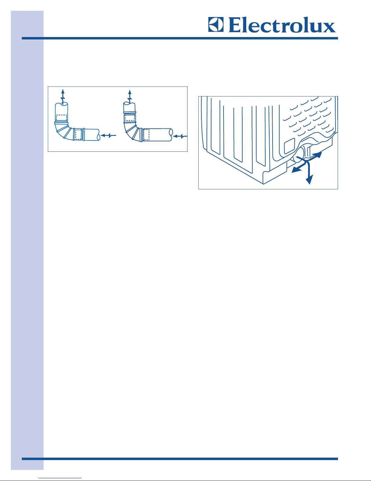
EExxhhaauusstt DDiirreeccttiioonn
Directional exhausting can be accomplished by
installing a quick-turn 90° dryer vent elbow directly
to exhaust outlet of dryer. Dryer vent elbows are
available through your local parts distributor or
hardware store. (See Figure 2-5)
MMaannuuffaaccttuurreedd oorr MMoobbiillee HHoommee IInnssttaallllaattiioonn
1. Installation MUST conform to current
Manufactured Home Construction & Safety
Standard, Title 24 CFR, Part 32-80 (formerly
the Federal Standard for Mobile Home
Construction and Safety, Title 24, HUD Part
280) or Standard CAN/CSAZ240 MH.
2. Dryer MUST be exhausted outside (outdoors,
not beneath the mobile home) using metal
ducting that will not support combustion.
Metal ducting must be 4 inches (10.16 cm) in
diameter with no obstructions. Rigid metal
duct is preferred.
3. If dryer is exhausted through the floor and area
beneath the mobile home is enclosed, the
exhaust system MUST terminate outside the
enclosure with the termination securely
fastened to the mobile home structure.
4. Refer to previous sections in this guide for
other important exhaust venting system
requirements.
5. When installing a gas dryer into a mobile
home, a provision must be made for outside
make up air. This provision is to be not less
than twice the area of the dryer exhaust outlet.
6. Installer MUST anchor this (1) dryer or (2)
dryer mounted on pedestal to the floor with
approved Mobile Home Installation Kit.
FFiigguurree 22--44..
FFiigguurree 22--55..
CORRECT
INCORRECT
IInnssttaallllaattiioonn IInnffoorrmmaattiioonn
2-7
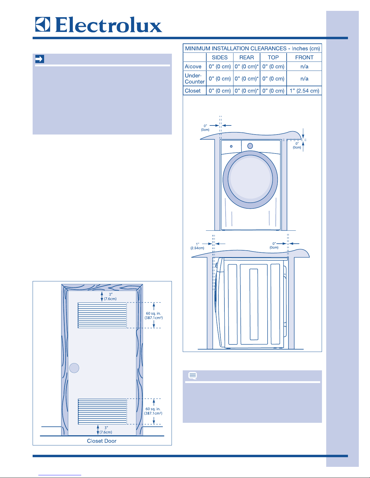
CClleeaarraannccee RReeqquuiirreemmeennttss
IInnssttaallllaattiioonn iinn aa RReecceessss oorr CClloosseett
1. A dryer installed in a bedroom, bathroom,
recess or closet, MUST be exhausted out
doors.
2. No other fuel burning appliance shall be
installed in the same closet as the gas dryer.
3. The dryer needs the space around it for proper
ventilation.
DDOO NNOOTT
install dryer in a closet
with a solid door.
4. Closet door ventilation required: A minimum of
120 square inches (774.2 cm²) of opening,
equally divided at the top and bottom of door,
is required. Openings should be located 3
inches (7.6 cm) from bottom and top of door.
Openings are required to be unobstructed
when a door is installed. A louvered door with
equivalent air openings for the full length of
door is acceptable. (See Figure 2-6 & 2-7)
DDOO NNOOTT IINNSSTTAALLLL TTHHEE DDRRYYEERR::
11.. IInn aann aarreeaa eexxppoosseedd ttoo ddrriippppiinngg wwaatteerr oorr oouutt
ssiiddee wweeaatthheerr ccoonnddiittiioonnss..
22.. IInn aann aarreeaa wwhheerree iitt wwiillll ccoommee iinn ccoonnttaacctt wwiitthh
ccuurrttaaiinnss,, ddrraappeess,, oorr aannyytthhiinngg tthhaatt wwiillll oobbssttrruucctt
tthhee ffllooww ooff ccoommbbuussttiioonn aanndd
vveennttiillaattiioonn aaiirr..
33.. OOnn ccaarrppeett.. FFlloooorr MMUUSSTT bbee ssoolliidd wwiitthh aa
mmaaxxiimmuumm ssllooppee ooff 11 iinncchh ((22..5544 ccmm))..
TToo aacchhiieevvee aann iinnssttaallllaattiioonn wwiitthh 00”” ((00ccmm))
cclleeaarraannccee ffoorr tthhee bbaacckk ooff tthhee ddrryyeerr ((ffoorr ootthheerr
tthhaann ssttrraaiigghhtt bbaacckk vveennttiinngg)),, aa qquuiicckk--ttuurrnn 9900°°
ddrryyeerr vveenntt eellbbooww mmuusstt bbee iinnssttaalllleedd aass ddeessccrriibbeedd
pprreevviioouussllyy iinn tthhiiss mmaannuuaall..
FFiigguurree 22--66..
FFiigguurree 22--77..
IMPORTANT
NOTE
IInnssttaallllaattiioonn IInnffoorrmmaattiioonn
2-8
EElleeccttrriiccaall SSyysstteemm RReeqquuiirreemmeennttss
Circuit - Individual 30 amp. branch circuit fused
with 30 amp. time delay fuses or circuit breakers.
Use separately fused circuits for washer and dryer.
DO NOT operate a washer and a dryer on the
same circuit.
Power Supply - 3-wire or 4-wire, 240 volt,
single phase, 60 Hz, Alternating Current.
33--WWiirree PPoowweerr SSuuppppllyy CCoorrdd KKiitt ((nnoott ssuupppplliieedd))
The dryer MUST employ a 3-conductor power
supply cord NEMA 10-30 type SRDT rated at
240 volt AC minimum, 30 amp, with 3 open end
spade lug connectors with upturned ends or
closed loop connectors and marked for use with
clothes dryers. For 3-wire cord connection
instructions see ELECTRICAL CONNECTIONS
FOR A 3-WIRE SYSTEM.
44--WWiirree PPoowweerr SSuuppppllyy CCoorrdd KKiitt ((nnoott ssuupppplliieedd))
The dryer MUST employ a 4-conductor power
supply cor
d NEMA 14-30 type SRDT or ST (as
required) rated at 240 volt AC minimum, 30 amp,
with 4 open end spade lug connectors with
upturned ends or closed loop connectors and
marked for use with clothes dryers. For 4-wire
cord connection instructions see ELECTRICAL
CONNECTIONS FOR A 4-WIRE SYSTEM.
BBeeccaauussee ooff ppootteennttiiaallllyy iinnccoonnssiisstteenntt vvoollttaaggee
ccaappaabbiilliittiieess,, tthhee uussee ooff tthhiiss ddrryyeerr wwiitthh ppoowweerr
ccrreeaatteedd bbyy ggaass ppoowweerreedd ggeenneerraattoorrss,, ssoollaarr ppooww--
eerreedd ggeenneerraattoorrss,, wwiinndd ppoowweerreedd ggeenneerraattoorrss oorr
aannyy ootthheerr ggeenneerraattoorr ootthheerr tthhaann tthhee llooccaall uuttiilliittyy
ccoommppaannyy iiss nnoott rreeccoommmmeennddeedd..
GGFFII ((GGrroouunndd FFaauulltt IInntteerrrruupptteerr)) rreecceeppttaaccllee iiss
nnoott rreeqquuiirreedd..
DDrryyeerrss mmaannuuffaaccttuurreedd ffoorr ssaallee iinn CCaannaaddaa hhaavvee
ffaaccttoorryy--iinnssttaalllleedd,, 44--wwiirree ppoowweerr ssuuppppllyy ccoorrdd
((NNEEMMAA 1144--3300RR))..
TThhiiss ddrryyeerr iiss iinntteerrnnaallllyy ggrroouunnddeedd ttoo nneeuuttrraall
uunnlleessss iitt wwaass mmaannuuffaaccttuurreedd ffoorr ssaallee iinn CCaannaaddaa..
GGrroouunnddiinngg tthhrroouugghh tthhee nneeuuttrraall lliinnkk iiss pprroohhiibbiitteedd
ffoorr:: ((11)) nneeww bbrraanncchh cciirrccuuiitt iinnssttaallllaattiioonnss,, ((22))
mmoobbiillee hhoommeess,, ((33)) rreeccrreeaattiioonnaall vveehhiicclleess,, aanndd ((44))
aarreeaass wwhheerree llooccaall ccooddeess ddoo nnoott ppeerrmmiitt ggrroouunndd--
iinngg tthhrroouugghh tthhee nneeuuttrraall..
OOuuttlleett RReecceeppttaaccllee
NEMA 10-30R or NEMA 14-30R receptacle to be
located so the power supply cord is accessible
when the dryer is in the installed position.
EElleeccttrriiccaall RReeqquuiirreemmeennttss ffoorr GGaass DDrryyeerr::
Circuit - Individual, properly polarized and
grounded 15 amp. branch circuit fused with 15
amp. time delay fuse or circuit breaker.
Power Supply - 2-wire, with ground, 120 volt,
single phase, 60 Hz, Alternating Current.
Power Supply Cord - The dryer is equipped
with a 120 volt 3-wire power cord.
Grounding Connection - See “Grounding
requirements” in Electrical Installation section.
NOTE
IMPORTANT
NOTE

IInnssttaallllaattiioonn IInnffoorrmmaattiioonn
2-9
EElleeccttrriiccaall IInnssttaallllaattiioonn
FFoorr aa GGrroouunnddeedd,, CCoorrdd--ccoonnnneecctteedd DDrryyeerr::
((UU..SS..AA.. EElleeccttrriicc DDrryyeerr))
1. The dryer MUST be grounded. In the event of
a malfunction or breakdown, grounding will
reduce the risk of electrical shock by a path of
least resistance for electrical current.
2. After you purchase and install a 3 wire or 4
wire power supply cord having an equipment
grounding conductor and a grounding plug
that matches your wiring system, the plug
MUST be plugged into an appropriate, copper
wired receptacle that is properly installed and
grounded in accordance with all local codes
and ordinances. If in doubt, call a licensed
electrician.
DDOO NNOOTT
modify the plug you’ve installed on this
appliance.
FFoorr aa ppeerrmmaanneennttllyy ccoonnnneecctteedd ddrryyeerr::
1.
The dryer MUST be connected to a grounded
metal, permanent wiring system; or an
equipment grounding conductor must be run
with the circuit conductors and connected to
the equipment-grounding terminal or lead on
the appliance.
FFoorr aa GGrroouunnddeedd,, CCoorrdd--ccoonnnneecctteedd DDrryyeerr::
((CCaannaaddaa EElleeccttrriicc DDrryyeerr))
1.
The dryer MUST be grounded. In the event of
a malfunction or breakdown, grounding will
reduce the risk of electrical shock by a path of
least resistance for electrical current.
2. Since your dryer is equipped with a power
supply cord having an equipment-grounding
conductor and a grounding plug, the plug
must be plugged into an appropriate outlet
that is properly installed and grounded in
accordance with all local codes and
ordinances. If in doubt, call a licensed
electrician.
DDOO NNOOTT
modify the plug provided with the
appliance.
GGaass DDrryyeerr
1. The dryer is equipped with a three-prong
(grounding) plug for your protection against
shock hazard and should be plugged directly
into a properly grounded three-prong
receptacle.
DDOO NNOOTT
cut or remove ground prong from the
plug.
DDOO NNOOTT UUSSEE AANN EEXXTTEENNSSIIOONN CCOORRDD WWIITTHH TTHHIISS DDRRYYEERR.. SSOOMMEE EEXXTTEENNSSIIOONN CCOORRDDSS AARREE NNOOTT
DDEESSIIGGNNEEDD TTOO WWIITTHHSSTTAANNDD TTHHEE AAMMOOUUNNTTSS OOFF EELLEECCTTRRIICCAALL CCUURRRREENNTT TTHHIISS DDRRYYEERR UUTTIILLIIZZEESS AANNDD
CCAANN MMEELLTT,, CCRREEAATTIINNGG EELLEECCTTRRIICCAALL SSHHOOCCKK AANNDD//OORR FFIIRREE HHAAZZAARRDD.. LLOOCCAATTEE TTHHEE DDRRYYEERR WWIITTHHIINN
RREEAACCHH OOFF TTHHEE RREECCEEPPTTAACCLLEE FFOORR TTHHEE LLEENNGGTTHH PPOOWWEERR CCOORRDD TTOO BBEE PPUURRCCHHAASSEEDD,, AALLLLOOWWIINNGG
SSOOMMEE SSLLAACCKK IINN TTHHEE CCOORRDD..
AA UU..LL..--AAPPPPRROOVVEEDD SSTTRRAAIINN RREELLIIEEFF MMUUSSTT BBEE IINNSSTTAALLLLEEDD OONNTTOO PPOOWWEERR CCOORRDD.. IIFF TTHHEE SSTTRRAAIINN
RREELLIIEEFF IISS NNOOTT AATTTTAACCHHEEDD,, TTHHEE CCOORRDD CCAANN BBEE PPUULLLLEEDD OOUUTT OOFF TTHHEE DDRRYYEERR AANNDD CCAANN BBEE CCUUTT BBYY
AANNYY MMOOVVEEMMEENNTT OOFF TTHHEE CCOORRDD,, RREESSUULLTTIINNGG IINN EELLEECCTTRRIICCAALL SSHHOOCCKK..
DDOO NNOOTT UUSSEE AANN AALLUUMMIINNUUMM WWIIRREEDD RREECCEEPPTTAACCLLEE WWIITTHH AA CCOOPPPPEERR WWIIRREEDD PPOOWWEERR CCOORRDD AANNDD
PPLLUUGG ((OORR VVIICCEE VVEERRSSAA)).. AA CCHHEEMMIICCAALL RREEAACCTTIIOONN OOCCCCUURRSS BBEETTWWEEEENN CCOOPPPPEERR AANNDD AALLUUMMIINNUUMM
AANNDD CCAANN CCAAUUSSEE EELLEECCTTRRIICCAALL SSHHOORRTTSS.. TTHHEE PPRROOPPEERR WWIIRRIINNGG AANNDD RREECCEEPPTTAACCLLEE IISS AA CCOOPPPPEERR
WWIIRREEDD PPOOWWEERR CCOORRDD WWIITTHH AA CCOOPPPPEERR WWIIRREEDD RREECCEEPPTTAACCLLEE..
IInnssttaallllaattiioonn IInnffoorrmmaattiioonn
2-10
FFiigguurree 22--99..
FFiigguurree 22--88..
EElleeccttrriiccaall CCoonnnneeccttiioonn ((nnoonn--CCaannaaddaa)) -- 33 WWiirree CCoorrdd
1. Turn off power supply to outlet.
2. Remove the screw securing the terminal block
access cover in the lower corner on the back
of the dryer.
3. Install a UL-approved strain relief according
to the power cord/strain relief manufacturer’s
instructions in the power cord entry hole below
the access panel. At this time, the strain relief
should be loosely in place.
4. Thread an UNPLUGGED, UL-approved, 30
amp. power cord, NEMA 10-30 type SRDT,
through the strain relief.
5. Attach the power cord neutral (center wire)
conductor to the SILVER colored center
terminal on the terminal block. Tighten the
screw securely. (See Figure 2-8 & 2-9)
6. Attach the remaining two power cord outer
conductors to the outer, BRASS colored
terminals on the terminal block. Tighten both
screws securely.
7. Follow manufacturer’s guidelines for firmly
securing the strain relief and power cord.
8. Reinstall the terminal block cover.
EELLEECCTTRRIICCAALL SSHHOOCCKK HHAAZZAARRDD
FFAAIILLUURREE TTOO DDIISSCCOONNNNEECCTT PPOOWWEERR SSOOUURRCCEE
BBEEFFOORREE SSEERRVVIICCIINNGG CCOOUULLDD RREESSUULLTT IINN
PPEERRSSOONNAALL IINNJJUURRYY OORR EEVVEENN DDEEAATTHH..
EELLEECCTTRRIICCAALL SSHHOOCCKK HHAAZZAARRDD
DDOO NNOOTT MMAAKKEE AA SSHHAARRPP BBEENNDD OORR CCRRIIMMPP
WWIIRRIINNGG// CCOONNDDUUCCTTOORR AATT CCOONNNNEECCTTIIOONNSS..
IIff mmoovviinngg ddrryyeerr ffrroomm aa 44--wwiirree ssyysstteemm aanndd
iinnssttaalllliinngg iitt iinn aa 33--wwiirree ssyysstteemm,, mmoovvee tthhee iinntteerrnnaall
ggrroouunndd ffrroomm tthhee cceenntteerr tteerrmmiinnaall bbaacckk ttoo tthhee
GGRREEEENN ssccrreeww nneexxtt ttoo tthhee tteerrmmiinnaall bblloocckk..
IIff aa tteerrmmiinnaall ssccrreeww ffaallllss dduurriinngg ccoorrdd iinnssttaallllaattiioonn,,
iitt ccaann bbee rreettrriieevveedd iinn tthhee tteerrmmiinnaall ssccrreeww
rreeccoovveerryy sslloott bbeellooww tthhee aacccceessss ppaanneell..
30 Amp
NEMA 10-30
Neutral
(Center Wire)
Access Cover
Screw
Terminal
Block
Line 2
Brass Terminal
Neutral
Silver Terminal
Line 1
Brass Terminal
Internal Ground
Green Screw
Install
UL-approved
strain relief here
Terminal Screw
Recovery Slot
IMPORTANT
NOTE
Do Not remove
internal ground in
a 3-wire system
Neutral terminal
IInnssttaallllaattiioonn IInnffoorrmmaattiioonn
2-11
FFiigguurree 22--1111..
FFiigguurree 22--1100..
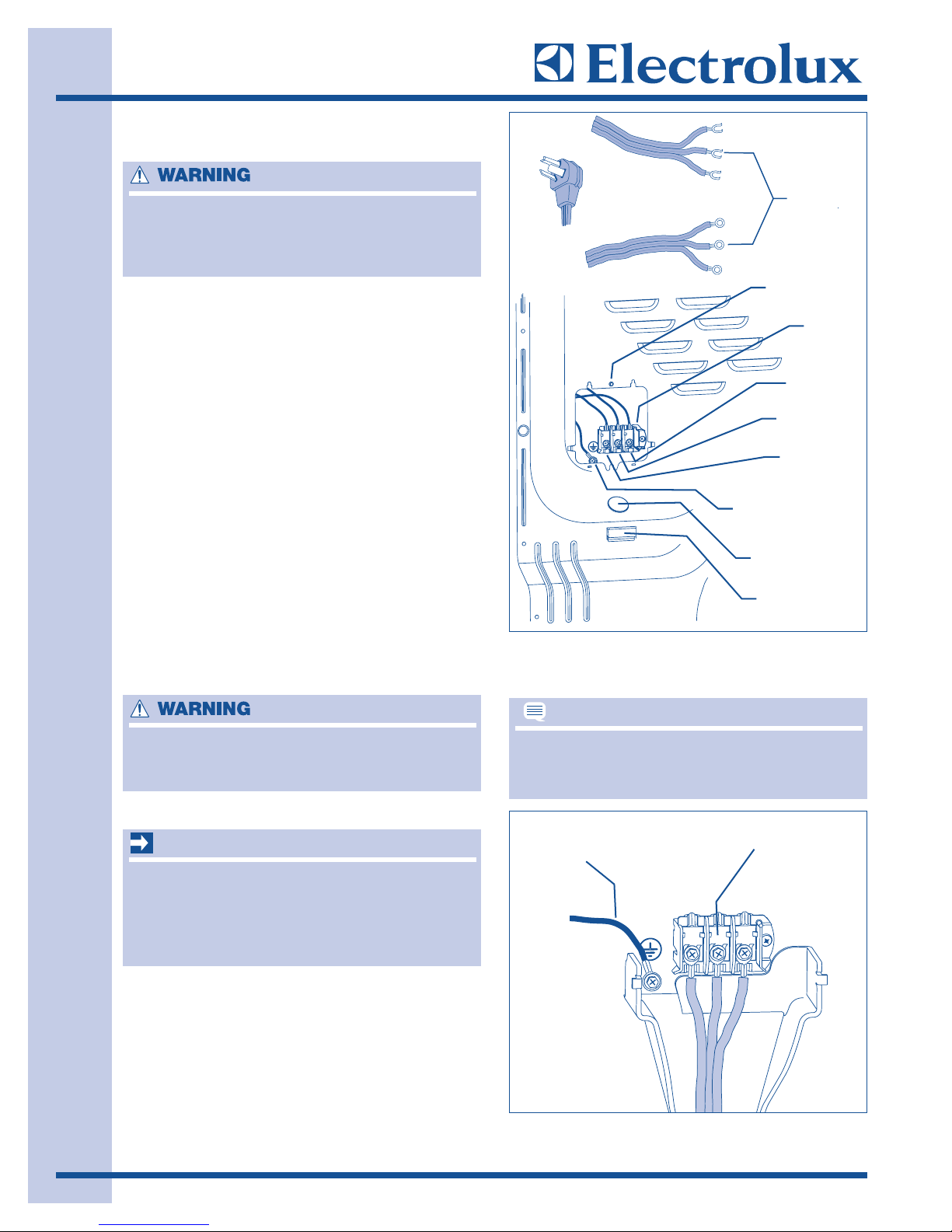
EElleeccttrriiccaall CCoonnnneeccttiioonn ((nnoonn--CCaannaaddaa)) -- 44 WWiirree CCoorrdd
1. Turn off power supply to outlet.
2. Remove the screw securing the terminal block
access cover in the lower corner on the back
of the dryer.
3. Install a UL-approved strain relief according
to the power cord/strain relief manufacturer’s
instructions in the power cord entry hole below
the access panel. At this time, the strain relief
should be loosely in place.
4. Thread an UNPLUGGED, UL-approved, 30
amp. power cord, NEMA 14-30 type ST or
SRDT, through the strain relief.
(See Figure 2-10)
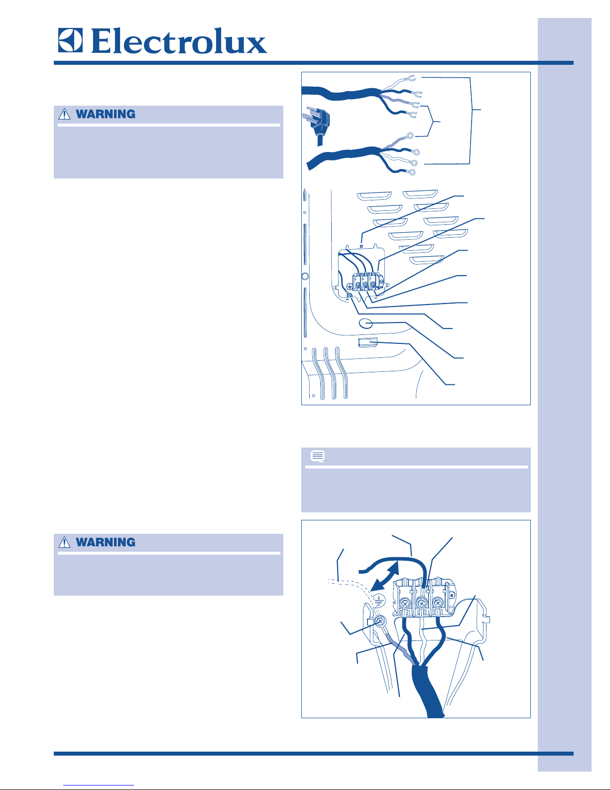
5. Disconnect the internal (BLACK) dryer harness
ground wire from the (GREEN) ground screw
next to the terminal block. (See Figure 2-11)
6. Attach the ground (GREEN) power cord wire
to the cabinet with the ground (GREEN) screw.
Tighten the screw securely.
7. Move the internal dryer harness ground
(BLACK) wire to the terminal block and attach
it along with the neutral (WHITE) power cord
wire conductor to the center, SILVER colored
terminal on the terminal block. Tighten the
screw securely.
8. Attach the RED and BLACK power cord
conductors to the outer, BRASS colored
terminals on the terminal block. Tighten both
screws securely.
9. Follow manufacturer’s guidelines for firmly
securing the strain relief and power cord.
10. Reinstall the terminal block cover..
EELLEECCTTRRIICCAALL SSHHOOCCKK HHAAZZAARRDD
FFAAIILLUURREE TTOO DDIISSCCOONNNNEECCTT PPOOWWEERR SSOOUURRCCEE
BBEEFFOORREE SSEERRVVIICCIINNGG CCOOUULLDD RREESSUULLTT IINN
PPEERRSSOONNAALL IINNJJUURRYY OORR EEVVEENN DDEEAATTHH..
EELLEECCTTRRIICCAALL SSHHOOCCKK HHAAZZAARRDD
DDOO NNOOTT MMAAKKEE AA SSHHAARRPP BBEENNDD OORR CCRRIIMMPP
WWIIRRIINNGG// CCOONNDDUUCCTTOORR AATT CCOONNNNEECCTTIIOONNSS..
IIff aa tteerrmmiinnaall ssccrreeww ffaallllss dduurriinngg ccoorrdd iinnssttaallllaattiioonn,,
iitt ccaann bbee rreettrriieevveedd iinn tthhee tteerrmmiinnaall ssccrreeww
rreeccoovveerryy sslloott bbeellooww tthhee aacccceessss ppaanneell..
30 Amp
NEMA 14-30
Ground
Green
wire
Neutral
White wire
Access Cover
Screw
Terminal
Block
Line 2
Brass Terminal
Neutral
Silver Terminal
Line 1
Brass Terminal
Internal Ground
Green Screw
Install
UL-approved
strain relief here
Terminal Screw
Recovery Slot
NOTE
Move internal ground (Black)
wire to neutral (Silver)
terminal for 4-wire system
Neutral terminal
Green
ground screw
Green
ground wire
Neutral
White wire
Black or Red
power wire
Black or Red
power wire
IInnssttaallllaattiioonn IInnffoorrmmaattiioonn
2-12
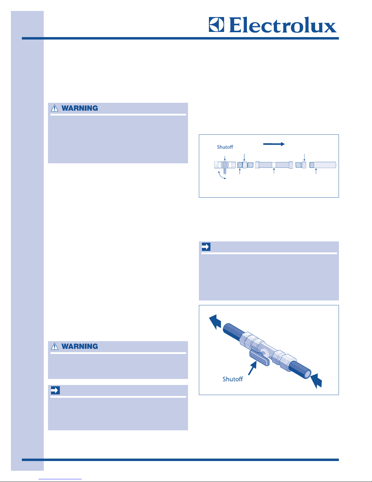
GGaass CCoonnnneeccttiioonn
1. Remove the shipping cap from gas pipe at the
rear of the dryer.
2. Connect a 1/2 inch (1.27 cm) I.D. semi-rigid or
approved pipe from gas supply line to the 3/8
inch (0.96 cm) pipe located on the back of the
dryer. Use a 1/2 inch to 3/8 inch (1.27 cm to
0.96 cm) reducer for the connection. Apply an
approved thread sealer that is resistant to the
corrosive action of liquefied gases on all pipe
connections. (See Figure 2-12)
3. Open the shutoff valve in the gas supply line to
allow gas to flow through the pipe. Wait a few
minutes for gas to move through the gas line.
4. Check for gas system leaks with a manometer.
If a manometer is not available, test all
connections by brushing on a soapy water
solution.
GGaass SSuuppppllyy RReeqquuiirreemmeennttss
1. Installation MUST conform with local codes, or
in the absence of local codes, with the
National Fuel Gas Code, ANSI Z223.1 (latest
edition).
2. The gas supply line should be 1/2 inch
(1.27cm) pipe.
3. If codes allow, flexible metal tubing may be
used to connect your dryer to the gas supply
line. The tubing MUST be constructed of
stainless steel or plastic-coated brass.
4. The gas supply line MUST have an individual
shutoff valve.
5. A 1/8 inch (0.32 cm) N.P.T. plugged tapping,
accessible for test gauge connection, MUST
be installed immediately upstream of the gas
supply connection to the dryer.
6. The dryer MUST be disconnected from the gas
supply piping system during any pressure
testing of the gas supply piping system at test
pressures in excess of 1/2 psig (3.45 kPa).
7. The dryer MUST be isolated from the gas
supply piping system during any pressure
testing of the gas supply piping system at test
pressures equal to or less than 1/2 psig
(3.45 kPa).
8. Connections for the gas supply must comply
with the Standard for Connectors for Gas
Appliances, ANSI Z21.24.
DDOO NNOOTT ccoonnnneecctt tthhee ddrryyeerr ttoo LL..PP.. ggaass sseerrvviiccee
wwiitthhoouutt ccoonnvveerrttiinngg tthhee ggaass vvaallvvee.. AAnn LL..PP..
ccoonnvveerrssiioonn kkiitt mmuusstt bbee iinnssttaalllleedd bbyy aa
qquuaalliiffiieedd ggaass tteecchhnniicciiaann..
TThhee ssuuppppllyy lliinnee mmuusstt bbee eeqquuiippppeedd wwiitthh aann
aapppprroovveedd mmaannuuaall sshhuuttooffff vvaallvvee.. TThhiiss vvaallvvee
sshhoouulldd bbee llooccaatteedd iinn tthhee ssaammee rroooomm aass tthhee ddrryyeerr
aanndd sshhoouulldd bbee iinn aa llooccaattiioonn tthhaatt aalllloowwss eeaassee ooff
ooppeenniinngg aanndd cclloossiinngg.. DDoo nnoott bblloocckk aacccceessss ttoo tthhee
ggaass sshhuuttooffff vvaallvvee..
EEXXPPLLOOSSIIOONN HHAAZZAARRDD
NNEEVVEERR TTEESSTT FFOORR GGAASS LLEEAAKKSS WWIITTHH AANN OOPPEENN
FFLLAAMMEE..
EEXXPPLLOOSSIIOONN HHAAZZAARRDD
UUNNCCOOAATTEEDD CCOOPPPPEERR TTUUBBIINNGG WWIILLLL CCOORRRROODDEE
WWHHEENN SSUUBBJJEECCTTEEDD TTOO NNAATTUURRAALL GGAASS,,
CCAAUUSSIINNGG GGAASS LLEEAAKKSS.. UUSSEE OONNLLYY BBLLAACCKK
IIRROONN,, SSTTAAIINNLLEESSSS SSTTEEEELL,, OORR PPLLAASSTTIICC
CCOOAATTEEDD BBRRAASSSS PPIIPPIINNGG FFOORR GGAASS SSUUPPPPLLYY..
y
FFiigguurree 22--1122..
FFiigguurree 22--1133..
Closed
Manual
Valve
Open
Flare
Union
All connections must be wrench-tightened
elppiN
GAS FLOW
Flexible
Connector
Flare
Union
Inlet Pipe on
Back of Dryer
IMPORTANT
reyrd ot
IMPORTANT
lppus sag morf
Valve -
Open position
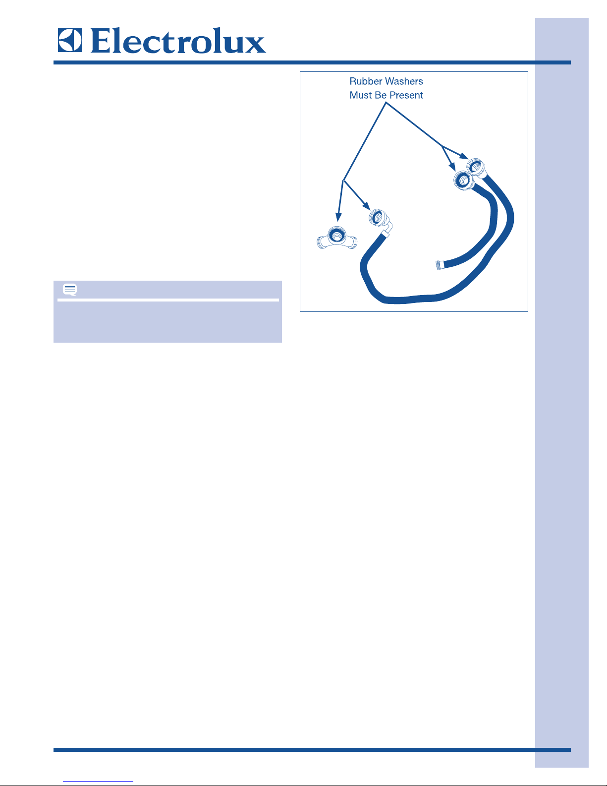
WWaatteerr CCoonnnneeccttiioonn ((SStteeaamm MMooddeell OOnnllyy))
1. Turn off COLD water supply to washer,
2. Remove COLD inlet hose from COLD water
supply and inspect for rubber washer. Replace
washer if it is torn or worn out.
3. Momentarily turn on COLD supply and run
some water into a bucket or container to clear
any contaminants in the line.
4. Remove hose kit from dryer drum and inspect
hose couplings for proper placement of rubber
washers. (See Figure 2-14)
5. If your installation has room for the COLD
water supply to accept the “Y” connector
directly, thread the “Y” connector to the COLD
water supply and snug it by hand; then tighten
it another 2/3 turn with pliers.
6. If there is not room to install the “Y” connector
directly, thread the short extension hose on to
the COLD water supply and snug it by hand;
then tighten it another 2/3 turn with pliers.
7. Thread the “Y” connector to the short
extension hose and snug it by hand; then
tighten it another 2/3 turn with pliers.
8. Connect the COLD inlet hose for the washer
to the “Y” connector and snug it by hand; then
tighten it another 2/3 turn with pliers.
9. Connect the straight end of the long hose from
the kit to the other outlet on the “Y” connector
and snug it by hand. Connect the hose’s 90°
coupling to the brass water inlet on the back
of the dryer and snug it by hand. Tighten each
connection of the dryer inlet hose another 2/3
turn with pliers.
10. Turn on the water and check for leaks at all
connections.
IInnssttaallllaattiioonn IInnffoorrmmaattiioonn
2-13
IIff yyoouu wweerree aabbllee ttoo iinnssttaallll tthhee ““YY”” ccoonnnneeccttoorr
ddiirreeccttllyy ttoo tthhee CCOOLLDD wwaatteerr ssuuppppllyy,, pplleeaassee sskkiipp
ttoo sstteepp 88..
FFiigguurree 22--1144..
NOTE
GGeenneerraall IInnssttaallllaattiioonn
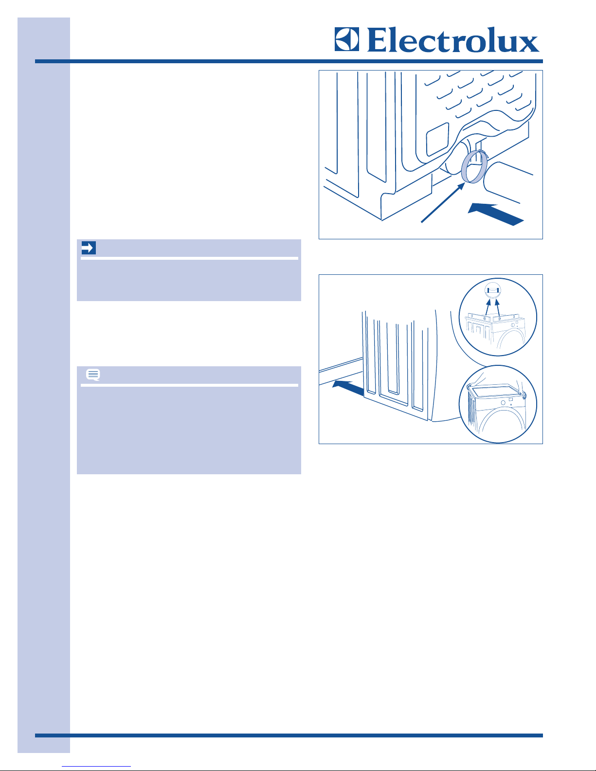
1. Connect the exhaust duct to the outside
exhaust system. Use of a 4” (10.2 cm) clamp
is recommended to connect the dryer to the
exhaust vent system. Use metal foil tape to
seal all other joints. (See Figure 2-15)
2. Carefully slide the dryer to its final position.
Adjust one or more of the legs until the dryer is
resting solidly on all four legs. Place a level on
top of the dryer. The dryer MUST be level and
resting solidly on all four legs. Rock alternating corners to check for stability. Remove and
discard door tape. (See Figure 2-16)
3. Plug the power cord into a grounded outlet.
4. Turn on power at the circuit breaker/fuse box.
5. Perform the “Installation Cycle” to verify proper
installation.
IInnssttaallllaattiioonn IInnffoorrmmaattiioonn
2-14
OOnn ggaass ddrryyeerrss,, bbeeffoorree tthhee bbuurrnneerr wwiillll lliigghhtt,, iitt iiss
nneecceessssaarryy ffoorr tthhee ggaass lliinnee ttoo bbee bblleedd ooff aaiirr.. IIff tthhee
bbuurrnneerr ddooeess nnoott lliigghhtt wwiitthhiinn 4455 sseeccoonnddss tthhee ffiirrsstt
ttiimmee tthhee ddrryyeerr iiss ttuurrnneedd oonn,, tthhee ssaaffeettyy sswwiittcchh wwiillll
sshhuutt tthhee bbuurrnneerr ooffff.. IIff tthhiiss hhaappppeennss,, pprreessss ccaanncceell
aanndd wwaaiitt 55 mmiinnuutteess bbeeffoorree mmaakkiinngg aannootthheerr
aatttteemmpptt ttoo lliigghhtt..
FFiigguurree 22--1155..
FFiigguurree 22--1166..
BBee ssuurree ppoowweerr iiss ooffff aatt aa cciirrccuuiitt bbrreeaakkeerr//ffuussee
bbooxx bbeeffoorree pplluuggggiinngg ppoowweerr ccoorrdd iinnttoo aann
oouuttlleett..
4” Clamp
IMPORTANT
NOTE

WWaavvee--TToouucchh™™ IInnssttaallllaattiioonn CCyyccllee
1. After plugging in the dryer the first time: wake
up the dryer by pressing any button and then
follow the prompts on the LCD User Interface,
including language selection.
2. The Installation Cycle will automatically test for
correct cord connection (on electric models),
presence of gas supply (on gas models) and
free flow of exhaust vent. At cycle completion,
the LCD user interface may display
IINNSSTTAALLLL
PPAASSSS!!
, meaning the dryer is properly installed
and ready for use. If it prompts an action such
as
SSEERRVVIICCEE CCOORRDD, NNOO GGAASS
or
CCaallll SSeerrvviiccee
887777--443355--33228877
, review the installation steps
and make the necessary corrections before
attempting to use the dryer
.
3. The dryer will exit the Installation Cycle and
return to normal operation the next time the
dryer is used.
IIQQ --TToouucchh™™ IInnssttaallllaattiioonn CCyyccllee
1. Empty dryer’s drum and close door.
2. After you plug in the dryer the first time: wake
up the dryer by pressing any button, rotate
cycle knob to touch up cycle, press the start
button and then the cancel button.
3. Wake up the dryer again by pressing any
button, then immediately and simultaneously
press and hold both the sanitize and my
favorite buttons for 5 seconds, or until the LCD
display changes.
4. The LCD window will display
IINNSSTTAALL CCYYCCLLEE
and show estimated time of cycle completion.
Press the start button. The Installation Cycle
will automatically test for correct cord
connection (on electric models) and presence
of gas supply (on gas models). At cycle
completion, the LCD window may display
IINNSSTTAALL PPAASSSS!!
, meaning the dryer is properly
installed and ready for use. If it prompts an
action such as
SSEERRVVIICCEE CCOORRDD,, NNOO GGAASS
or
CCaallll SSeerrvviiccee 887777--443355--33228877
, r
eview the
installation steps and make the necessary
corrections before attempting to use the dryer.
5. The washer will exit the Installation Cycle and
return to normal operation the next time the
washer is used.
IInnssttaallllaattiioonn IInnffoorrmmaattiioonn
2-15
DDrryyeerr wwiillll ssttaayy aawwaakkee ffoorr 33 mmiinnuutteess aafftteerr tthhee
IInnssttaallllaattiioonn CCyyccllee.. IIff yyoouu wwiisshh ttoo iimmmmeeddiiaatteellyy rruunn
tthhee ddrryyeerr tthhrroouugghh aa ddrryyiinngg ccyyccllee,, pprreessss tthhee ccaann--
cceell bbuuttttoonn ttoo ppuutt tthhee uunniitt ttoo sslleeeepp aanndd tthheenn
rreewwaakkee iitt iimmmmeeddiiaatteellyy,, ttoo ccoonnttiinnuuee tthhee nnoorrmmaall
ooppeerraattiinngg mmooddee..
NOTE
IInnssttaallllaattiioonn IInnffoorrmmaattiioonn
2-16
RReevveerrssiinngg DDoooorr
PPrreeppaarriinngg ttoo RReevveerrssee DDoooorr SSwwiinngg
1. Be sure you have adequate swing area before
reversing door.
2. You will need a screw driver with a #2 square
bit.
3. Protect flat work surface, such as top of
washer or floor near washer, with a soft cloth
or towel.
4. Be sure washer is unplugged from power
source.
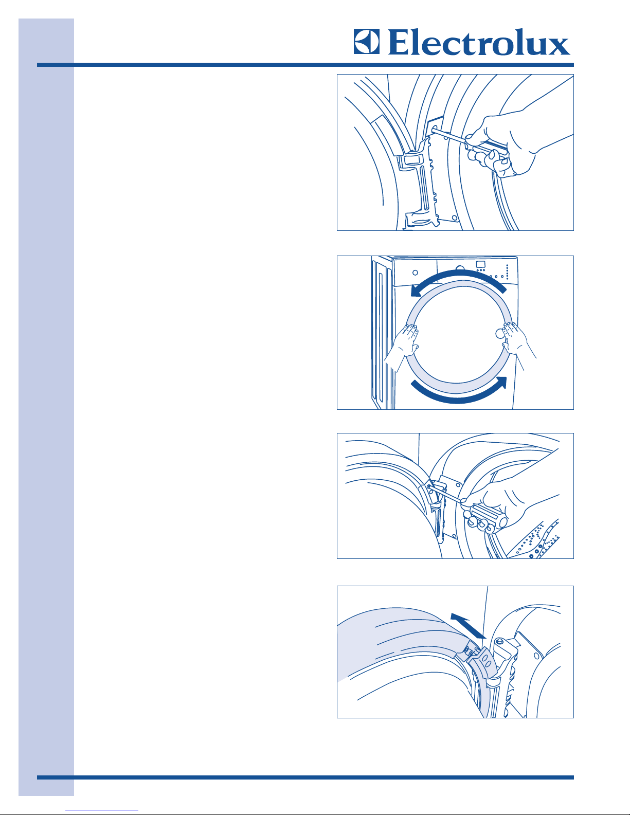
RReemmoovviinngg TTrriimm RRiinngg
1. Open the door to a 90 degree angle.
2. Remove and save the trim plug and long,
course-thread, panhead screw.
(See Figure 2-17)
3. Close the door.
4. Rotate the door trim approximately ¾”
counter-clockwise and pull it away from the
front of the door. (See Figure 2-18)
RReemmoovviinngg DDoooorr ffrroomm HHiinnggee
1. Reopen door to 90 degree angle.
2. Remove 4 long, course-thread, counter-sunk
hinge screws from door. (See Figure 2-19)
3. While supporting the weight of the door with
both hands, separate the door from the hinge.
(See Figure 2-20)
4. Gently place the door face down on a flat,
covered work surface.
FFiigguurree 22--1177..
FFiigguurree 22--1188..
FFiigguurree 22--1199..
FFiigguurree 22--2200..
IInnssttaallllaattiioonn IInnffoorrmmaattiioonn
2-17
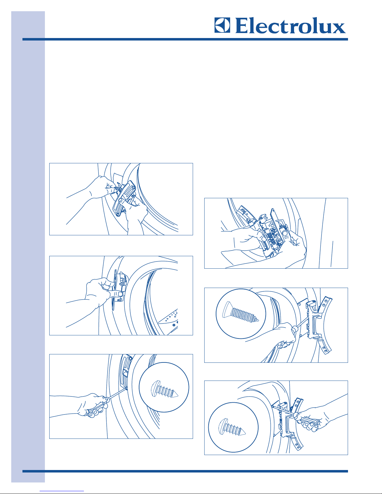
RReemmoovviinngg HHiinnggee ffrroomm FFrroonntt PPaanneell
1. With the hinge in open position, remove 2
short, course-thread, panhead screws on
hinge plate. (See Figure 2-21)
2. Remove 3 short, fine-thread, counter-sunk
screws in hinge side. (See Figure 2-22)
3. Slide the hinge toward the center of the front
panel, and then pivot the hinge inward while
slowly pulling it away from the front panel to
expose the attached harness.
4. Lift up on the tab and the release harness
from the retainer, allowing the harness to lay
outside the front panel. (See Figure 2-23)
RReemmoovviinngg DDoooorr LLoocckk ffrroomm FFrroonntt PPaanneell
1. Remove 2 short, course-thread, panhead
screws from the door lock.
(See Figure 2-24)
2. Slide the lock toward the outer edge of the
front panel. Pivot the lock slightly outward
while slowly pulling it through opening to
expose the attached harness.
(See Figure 2-25)
3. Release the harness from the terminal with
the small lever on back of the lock. Separate
the harness from the lock, allowing the
harness to lay outside the front panel.
(See Figure 2-26)
FFiigguurree 22--2211..
FFiigguurree 22--2222..
FFiigguurree 22--2233..
FFiigguurree 22--2244..
FFiigguurree 22--2255..
FFiigguurree 22--2266..
IInnssttaallllaattiioonn IInnffoorrmmaattiioonn
2-18
RReeaattttaacchhiinngg DDoooorr LLoocckk ttoo FFoonntt PPaanneell
1. Rotate the door lock and move it to the
opposite opening.
2. Connect the harness to the door lock by
inserting it in the terminal and firmly pushing
it in place. (See Figure 2-27)
3. Insert the harness connection through the
front panel first, and then pivot the lock until
it is flush. Slide the lock toward the center of
the front panel until the screw holes line up.
(See Figure 2-28)
4. Secure the lock with 2 short, course-thread,
panhead screws. (See Figure 2-29)
RReeaattttaacchhiinngg HHiinnggee ttoo FFrroonntt PPaanneell
1. Rotate the hinge and move it to the opposite
opening.
2. Connect the harness to the hinge retainer
by inserting it in the retention terminal and
gently pushing until you hear the fastening
tab click.
(See Figure 2-30)
3. Gently pull on the harness to be sure it is
secure.
4. Use the side locating pins to align the hinge
and install 1 short, fine-thread, counter-sunk
screw in the center hole of hinge side.
(See Figure 2-31)
5. Install the other 2 short, fine-thread, counter
sunk screws in upper and lower holes of hinge
side.
6. Install 2 short, course-thread, panhead
screws through hinge plate. (See Figure 2-32)
FFiigguurree 22--2277..
FFiigguurree 22--3300..
FFiigguurree 22--3311..
FFiigguurree 22--3322..
FFiigguurree 22--2299..
FFiigguurree 22--2288..
IInnssttaallllaattiioonn IInnffoorrmmaattiioonn
2-19
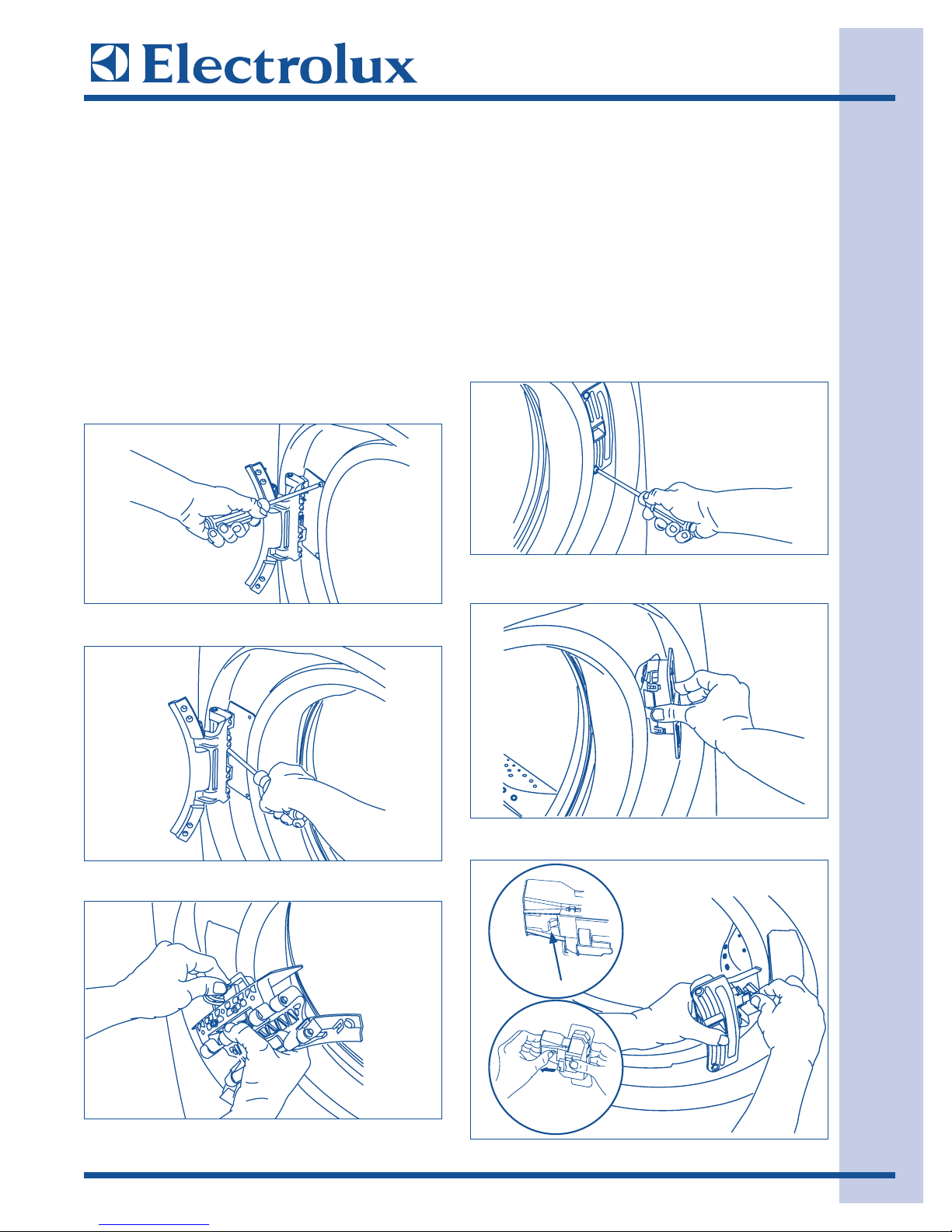
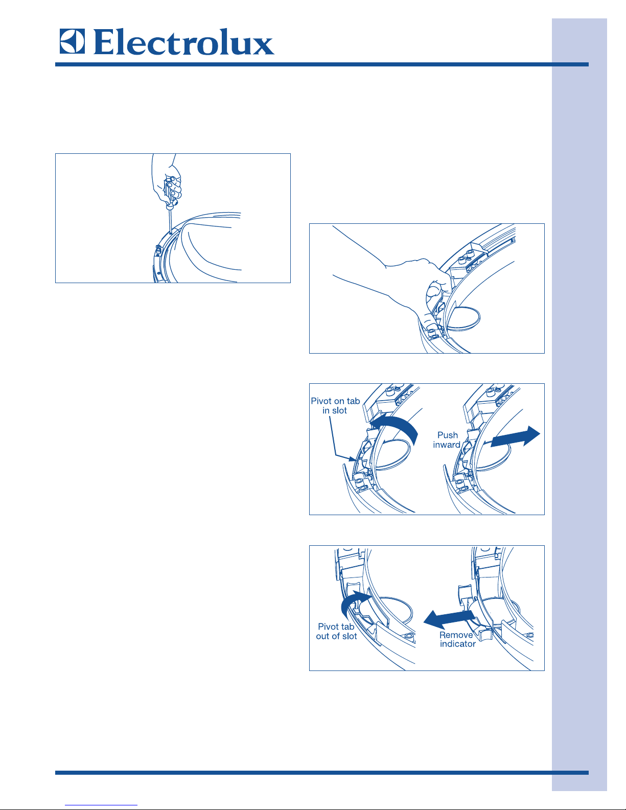
RReemmoovviinngg SSttrriikkeerr PPllaattee
1. Remove 2 long, course-thread, counter-sunk
screws and striker plate. (See Figure 2-33)
2. Set the striker plate to the side for later.
RReemmoovviinngg LLaattcchh IInnddiiccaattoorr
1. Grasp the indicator on the latch side
between finger and thumb and rock it
upward, pivoting away from the center of the
glass.
(See Figure 2-34)
2. Gently push the indicator toward the center
of the lens to release the tab.
3. Rock the tab upward.
(See Figure 2-35)
4. Pull the indicator out and set it aside.
(See Figure 2-36)
FFiigguurree 22--3333..
FFiigguurree 22--3344..
FFiigguurree 22--3355..
FFiigguurree 22--3366..
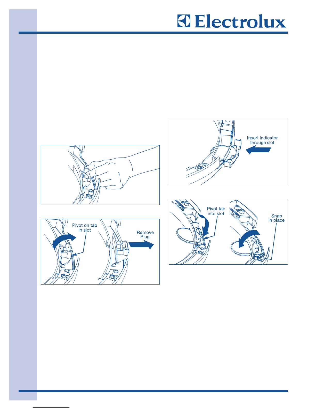
IInnssttaallllaattiioonn IInnffoorrmmaattiioonn
2-20
RReemmoovviinngg HHoollee PPlluugg
1. Grasp the hole plug between finger and
thumb and rock it upward, pivoting it away
from the center of the glass, releasing the
tab. (See Figure 2-37)
2. Connect the harness to the door lock by
inserting it in the terminal and firmly pushing
it in place.
3. Insert the harness connection through the
front panel first, and then pivot the lock until
it is flush. Slide the lock toward the center of
the front panel until the screw holes line up.
(See Figure 2-38)
4. Secure the lock with 2 short, course-thread,
panhead screws.
RReeiinnsseerrttiinngg LLaattcchh IInnddiiccaattoorr
1. Rotate the latch indicator and move it to the
opposite hole in the door.
2. Grasp the indicator between finger and
thumb and slide it through the opening.
(See Figure 2-39)
3. Gently push the indicator toward the center
of the glass and pivot the tab downward into
the retaining slot. (See Figure 2-40)
4. Pivot the indicator downward toward the
center of the glass until it is in place.
FFiigguurree 22--3377..
FFiigguurree 22--3388..
FFiigguurree 22--3399..
FFiigguurree 22--4400..
 Loading...