

Electrolux E30IC80ISS1, E30IC80QSS0, E36IC80ISS1, E36IC80QSS0, EW30IC60IB1 Installation Guide
...Page 1
UnitedStates
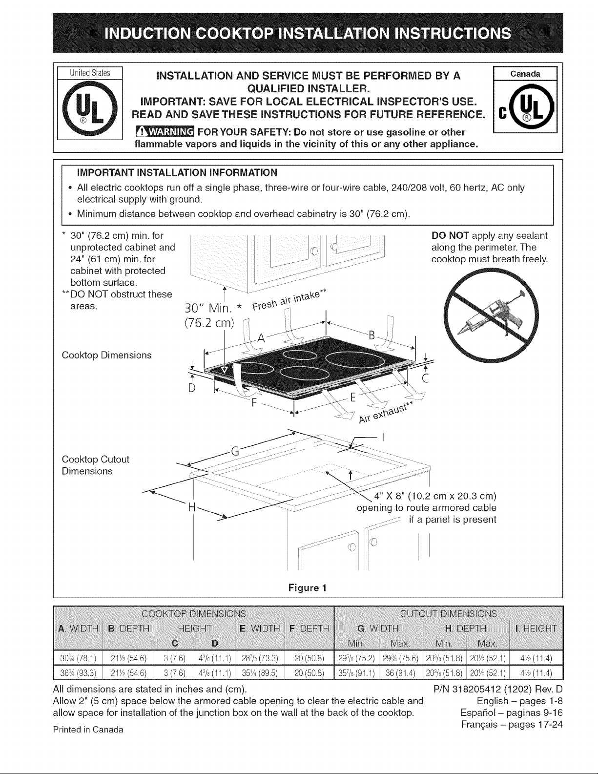
IMPORTANT INSTALLATION INFORMATION
= All electric cooktops run off a single phase, three-wire or four-wire cable, 240/208 volt, 60 hertz, AC only
electrical supply with ground.
= Minimum distance between cooktop and overhead cabinetry is 30" (76.2 cm).
INSTALLATION AND SERVICE MUST BE PERFORMED BY A
QUALiFiED iNSTALLER.
IMPORTANT: SAVE FOR LOCAL ELECTRICAL iNSPECTOR'S USE.
READ AND SAVE THESE iNSTRUCTiONS FOR FUTURE REFERENCE.
FOR YOUR SAFETY: Do not store or use gasoline or other
flammable vapors and liquids in the vicinity of this or any other appliance.
30" (76.2 cm) min. for
unprotected cabinet and
24" (61 cm) min. for
cabinet with protected
bottom surface,
** DO NOT obstruct these
areas.
Cooktop Dimensions
Cooktop Cutout
Dimensions
30" Min. *
(76.2 cm)
D
H
DO NOT apply any sealant
along the perimeter. The
cooktop must breath freely,
C
F
4" X 8" (10.2 cm x 20.3 cm)
opening to route armored cable
_/::::::::¢:: if a panel is present
i [_-....... :.,i
Figure 1
i_i_iiiiiiiiiiiiiiiiiiiiiiiiiiiiiiiiiiiiiiiiiiiiiiiiiiiiiiiiiiiiiiiiiiiiiiiiiiiiiiiiiiiiiiiiiii_i_iii_i_i_i_i_i_i!i!i_i!!!i_iiiiiiiiiiiii_@_i__iii_'!@@i_ii_i_@ii_!ii!ii!iiii_ili!
21_/p(54,6) 3(7,6) 43/8(11,1)
21_/p(54,6) 3(7,6) 43/8(11,1)
All dimensions are stated in inches and (cm).
Allow 2" (5 cm) space below the armored cable opening to clear the electric cable and
allow space for installation of the junction box on the wall at the back of the cooktop.
Printed in Canada
287/8(73,3)
35_(89.5)
20 (50,8)
20 (50,8)
29% (75,2)
357/8(91,1)
29:_(75,6)
36(91.4)
20%(51,8)
20sh(51,8)
P/N 318205412 (1202) Rev. D
English - pages 1-8
Espafiol - paginas 9-16
Frangais - pages 17-24
Page 2
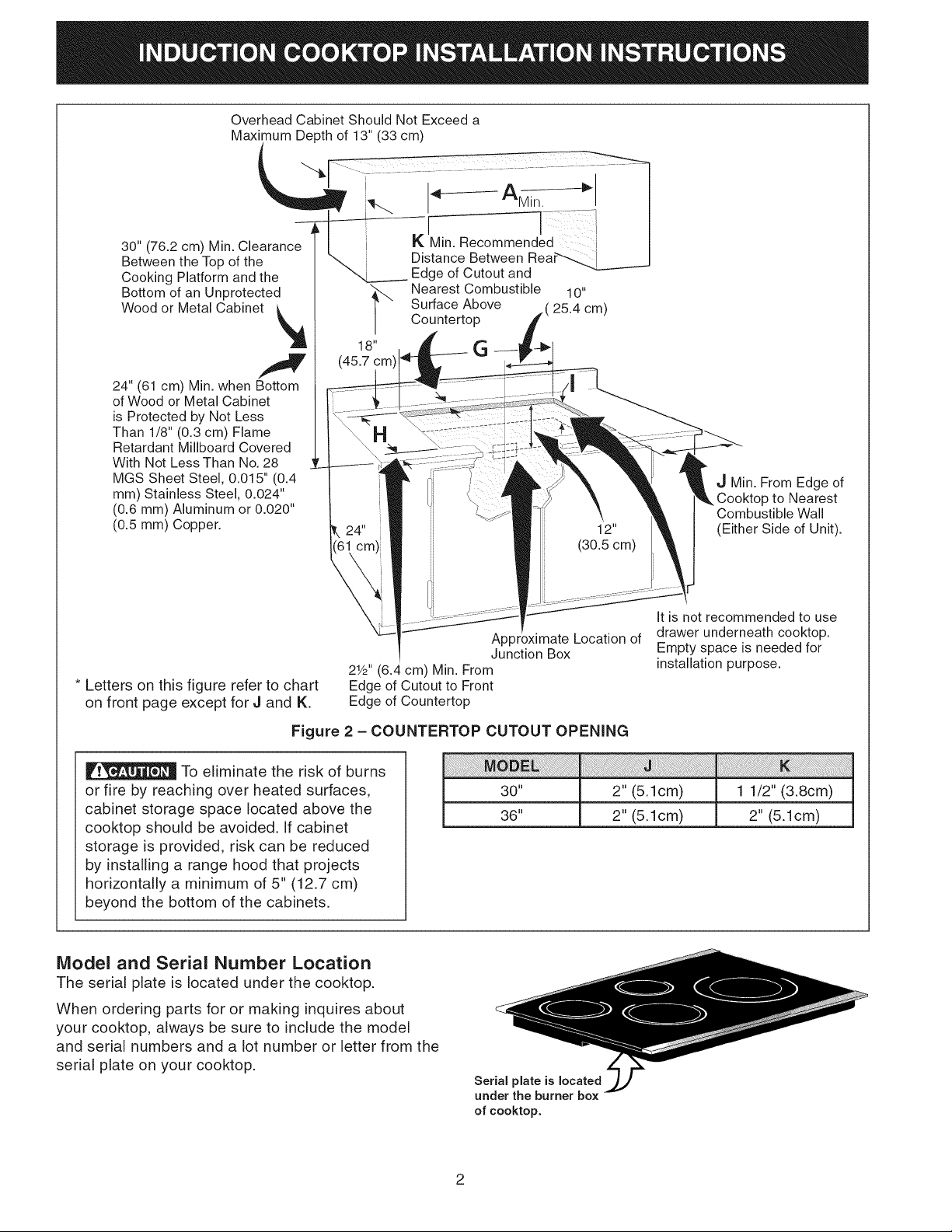
Overhead Cabinet Should Not Exceed a
Maximum Depth of 13" (33 cm)
30" (76.2 cm) Min. Cle ui
Between the Top of the
Cooking Platform and the
Bottom of an Unprotected
Wood or Metal Cabinet _A
1
24" (61 cm) Min. when Bottom
of Wood or Metal Cabinet
is Protected by Not Less
Than 1/8" (o.g cm) Flame
Netardant Millboard Covered
With Not Less Than No. 28
MGS Sheet Steel, 0.015" (0.4
mm) Stainless Steel, 0.024"
(0.6 ram) Aluminum or 0.020"
(0.5 mm) Copper.
"_ Nearest Combustible 10"
18" G
(45.7 cm)
...............I
Edge of Cutout and
Surface Above 25.4 cm)
Countertop
J Min. From Edge of
_.Cooktop to Nearest
Combustible Wall
(Either Side of Unit).
2Y2"(6.4 cm) Min. From
* Letters on this figure refer to chart
on front page except for J and K.
Edge of Cutout to Front
Edge of Countertop
Figure 2 - COUNTERTOP CUTOUT OPENING
To eliminate the risk of burns
or fire by reaching over heated surfaces,
cabinet storage space located above the
cooktop should be avoided. If cabinet
storage is provided, risk can be reduced
by installing a range hood that projects
horizontally a minimum of 5" (12.7 cm)
beyond the bottom of the cabinets.
Model and Serial Number Location
The serial plate is located under the cooktop.
When ordering parts for or making inquires about
your cooktop, always be sure to include the model
and serial numbers and a lot number or letter from the
serial plate on your cooktop.
Apl
Junction Box
i
30"
36"
Serial plate is located
under the burner box
of cooktop.
Location of
2" (5.1 cm)
2" (5.1 cm)
It is not recommended to use
drawer underneath cooktop.
Empty space is needed for
installation purpose.
J i ! !! ii !i ii i! ii i i !i!i i i iiiii i ii i! iiiiii ii i! i iiiii! ii!i iiiii ii!ii iiiiiiiiii!iiii i ii !i !! i iiii ii !! !!!i!!ii ii iiiiiiiiiiiiiiiiii i !ii ii!i i!!! i i!! !i!i !!i i! i! i! i i !ii ii ii ii
1 1/2" (3.8cm)
2" (5.1cm)
2
Page 3
Important Notes to the Installer
1. Read all instructions contained in these installation
instructions before installing the cooktop.
2. Remove all packing material before connecting the
electrical supply to the cooktop.
3. Observe all governing codes and ordinances.
4. Be sure to leave these instructions with the
consumer.
5. Only certain cooktop models may be installed over
certain built-in electric oven models. Approved
cooktops and built-in ovens are listed by the MFG ID
number and product code.
Important Note to the Consumer
Keep these instructions with your Use and Care Guide
for future reference.
An extension cord must not be used
with this appliance. Such use may result in a fire,
electrical shock, or other personal injury.
3. The appliance should be connected to the fused
disconnect (or circuit breaker) box through
flexible armored or nonmetallic sheathed cable.
The flexible armored cable extending from this
appliance should be connected directly to the
grounded junction box. The junction box should be
located as shown in Figure 2 with as much slack
as possible remaining in the cable between the box
and the appliance, so it can be moved if servicing
is ever necessary.
4. A suitable strain relief must be provided to attach
the flexible armored cable to the junction box.
I PO NT SAFETY
IoSTR CTI
Be sure your cooktop is installed and grounded
properly by a qualified installer or service
technician.
This cooktop must be electrically grounded in
accordance with local codes or, in their absence,
with the National Electrical Code ANSI/NFPA No.
70--latest edition in the United States.
The electrical power to the cooktop
must be shut off while line connections are being
made. Failure to do so could result in serious
injury or death.
Provide Electrical Connection
Install the junction box under the cabinet and run
120/240 or 120/208 Volt, AC wire from the main circuit
panel. NOTE: DO NOT connect the wire to the circuit
panel at this time.
Electrical Requirements
Observe all governing codes and local ordinances.
1. A 3-wire or 4-wire single phase 120/240 or
120/208 Volt, 60 Hz AC only electrical supply is
required on a separate circuit fused on both sides
of the line (time-delay fuse or circuit breaker is
recommended). DO NOT fuse neutral.
2. A circuit breaker or fuse rated at 50 Amp is
recommended (40 Amp minimum).
NOTE: Wire sizes and connections must conform with
the fuse size and rating of the appliance in accordance
with the National Electrical Code ANSI/NFPA No.
70-latest edition and local codes and ordinances.
Unpacking Instructions
1. Unpack and visually inspect the cooktop.
2. Be sure the bottle of cleaner conditioner packed
in the literature bag is left where the user can
find it easily. It is important that the ceramic-glass
cooktop be pretreated before use. See Cooktop
Cleaning and Maintenance section in the Use
and Care Guide,
Electrical Connection
Connect the flexible armored cable that extends from
the surface unit to the junction box using a suitable
strain relief at the point the armored cable enters the
junction box. Then make the electrical connection as
follows.
Electrical ground is required on this appliance.
This appliance is equipped with a
copper conductor flexible cable. If connection
is made to aluminum house wiring, use only
special connectors which are approved for joining
copper and aluminum wires in accordance with
the National Electrical Code and local codes and
ordinances. Improper connection of aluminum
house wiring to copper leads can result in a short
circuit or fire. Follow the connector manufacturer
recommended procedure closely.
This appliance is manufactured with a supply wire and
a frame connected green or bare copper grounding
wire.
DO NOT ground to a gas supply pipe.
DO NOT connect to electrical power supply until
appliance is permanently grounded. Connect the
ground wire before turning on the power.
3
Page 4
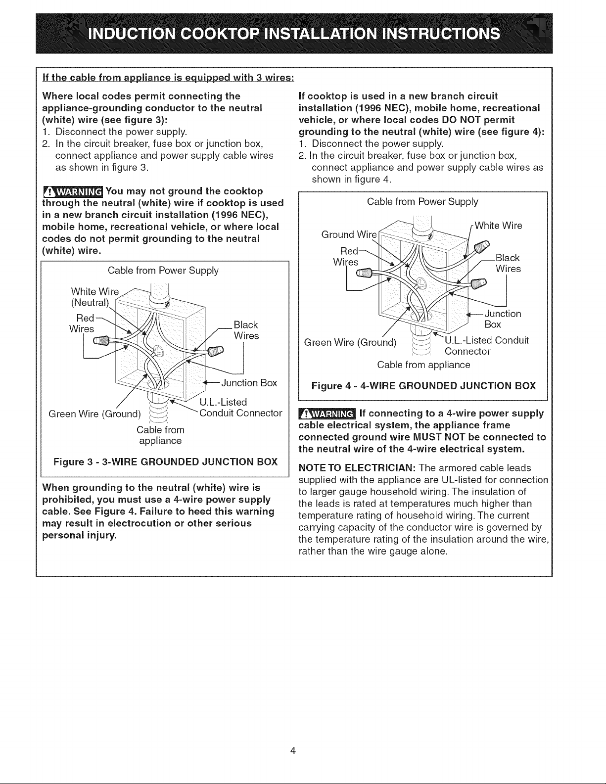
if the cable from agpliance is e_ed with 3 wires:
Where local codes permit connecting the
appliance-grounding conductor to the neutral
(white) wire (see figure 3):
1. Disconnect the power supply.
2. In the circuit breaker, fuse box or junction box,
connect appliance and power supply cable wires
as shown in figure 3.
You may not ground the cooktop
through the neutral (white) wire if cooktop is used
in a new branch circuit installation (1996 NEC),
mobile home, recreational vehicle, or where local
codes do not permit grounding to the neutral
(white) wire.
Cable from Power Supply
White Wire
(Neutral),,
Wires __ Black
Wires
Box
U.L.-Listed
Green Wire (Ground)
Conduit Connector
Cable from
appliance
Figure 3 =3=WIRE GROUNDED JUNCTION BOX
When grounding to the neutral (white) wire is
prohibited, you must use a 4-wire power supply
cable. See Figure 4. Failure to heed this warning
may result in electrocution or other serious
personal injury,
if cooktop is used in a new branch circuit
installation (1996 NEe), mobile home, recreational
vehicle, or where local codes DO NOT permit
grounding to the neutral (white) wire (see figure 4):
1. Disconnect the power supply.
2. In the circuit breaker, fuse box or junction box,
connect appliance and power supply cable wires as
shown in figure 4.
Cable from Power Supply
"_..__._ r White Wire
Ground Wire[_ ,.........[',,_-_--_
Red :!::::
Wire res
ion
..................IL ,
Green Wire (Gr°u-__'-nListted__v_ v_ Conduit
Cable from appliance
Figure 4 - 4-WIRE GROUNDED JUNCTION BOX
If connecting to a 4-wire power supply
cable electrical system, the appliance frame
connected ground wire MUST NOT be connected to
the neutral wire of the 4-wire electrical system.
NOTE TO ELECTRICIAN: The armored cable leads
supplied with the appliance are UL-listed for connection
to larger gauge household wiring. The insulation of
the leads is rated at temperatures much higher than
temperature rating of household wiring. The current
carrying capacity of the conductor wire is governed by
the temperature rating of the insulation around the wire,
rather than the wire gauge alone.
4
Page 5
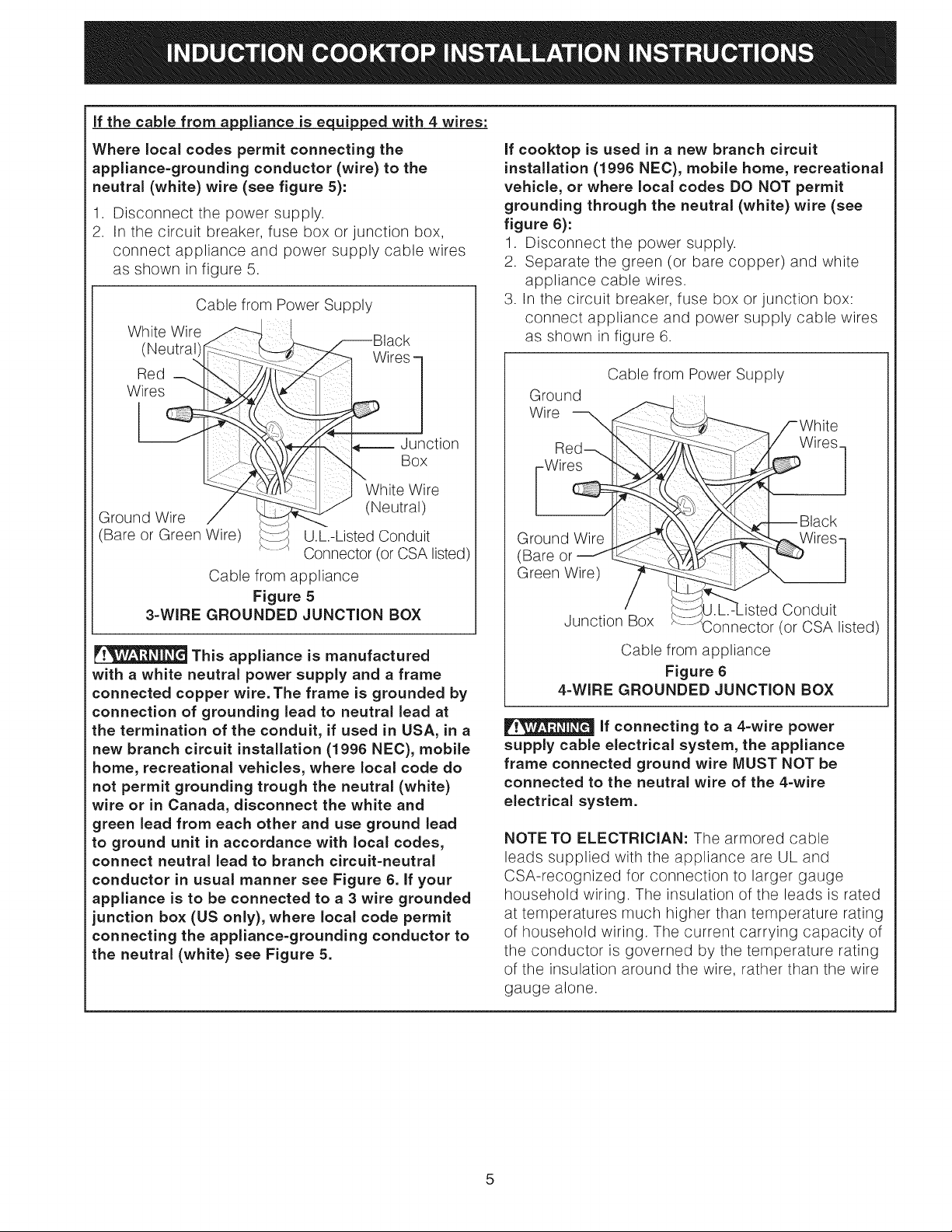
if the cable from ap_pliance is equipped with 4 wires:
Where local codes permit connecting the
appliance=grounding conductor (wire) to the
neutral (white) wire (see figure 5):
.
Disconnect the power supply.
2.
In the circuit breaker, fuse box or junction box,
connect appliance and power supply cable wires
as shown in figure 5.
Cable from Power Supply
White Wire _--_,,__,
(Neutra))r ?- :-_-ii
Wires
Black
ires -
f_----- ,Junction
"t-.
........11 _ "White Wire
Ground Wire J
(Bare or Green Wire)
Cable from appliance
Figure 5
3-WIRE GROUNDED JUNCTION BOX
This appliance is manufactured
with a white neutral power supply and a frame
connected copper wire, The frame is grounded by
connection of grounding lead to neutral lead at
the termination of the conduit, if used in USA, in a
new branch circuit installation (1996 NEC), mobile
home, recreational vehicles, where local code do
not permit grounding trough the neutral (white)
wire or in Canada, disconnect the white and
green lead from each other and use ground lead
to ground unit in accordance with local codes,
connect neutral lead to branch circuit-neutral
conductor in usual manner see Figure 6. if your
appliance is to be connected to a 3 wire grounded
junction box (US only), where local code permit
connecting the appliance=grounding conductor to
the neutral (white) see Figure 5,
"" (Neutral)
U.L.-Listed Conduit
Connector (or CSA listed)
if cooktop is used in a new branch circuit
installation (1996 NEC), mobile home, recreational
vehicle, or where local codes DO NOT permit
grounding through the neutral (white) wire (see
figure 6):
1. Disconnect the power supply.
2. Separate the green (or bare copper) and white
appliance cable wires.
3. In the circuit breaker, fuse box or junction box:
connect appliance and power supply cable wires
as shown in figure 6.
Cable from Power Supply
Ground
Wire
Wires]
-- Black
Ground Wire
(Bare or
Green Wire)
Conduit
Junction Box (or CSA listed)
Cable from appliance
Figure 6
4=WIRE GROUNDED JUNCTION BOX
if connecting to a 4=wire power
supply cable electrical system, the appliance
frame connected ground wire MUST NOT be
connected to the neutral wire of the 4=wire
electrical system.
NOTE TO ELECTRICIAN: The armored cable
leads supplied with the appliance are UL and
CSA-recognized for connection to larger gauge
household wiring. The insulation of the leads is rated
at temperatures much higher than temperature rating
of household wiring. The current carrying capacity of
the conductor is governed by the temperature rating
of the insulation around the wire, rather than the wire
gauge alone.
5
Page 6
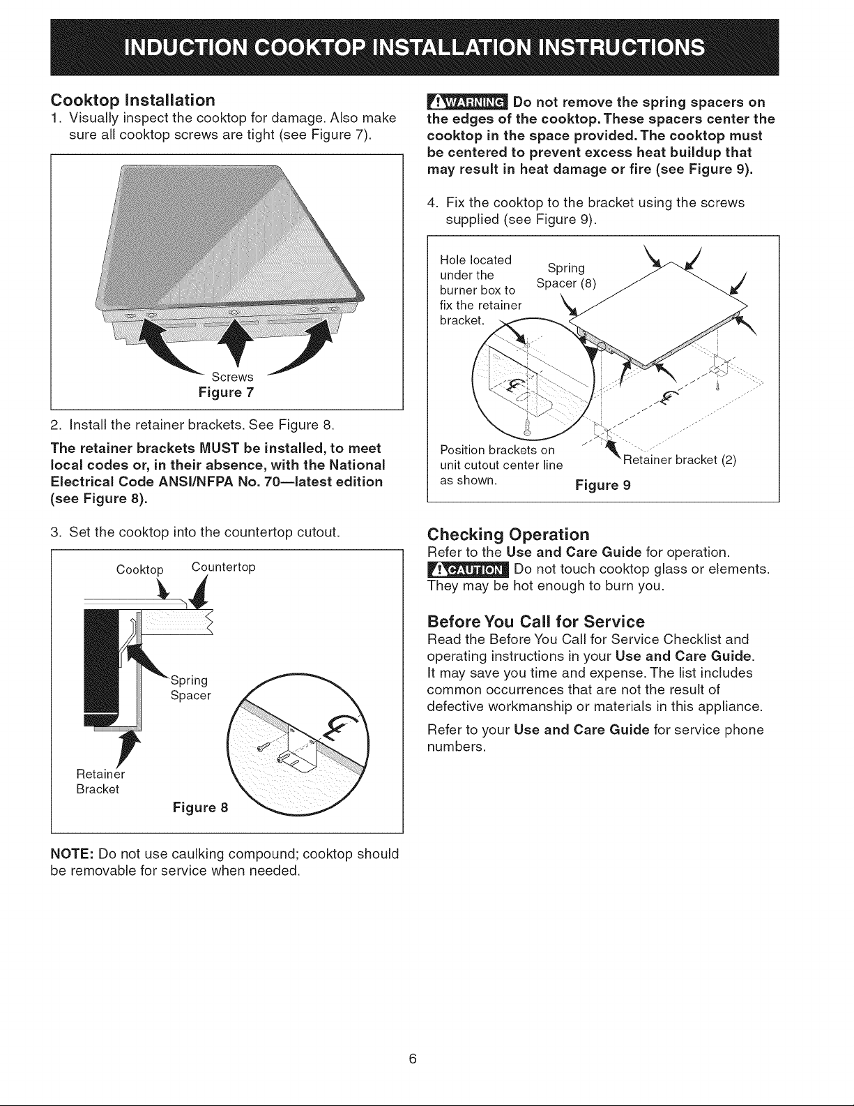
Cooktop Installation
1. Visually inspect the cooktop for damage. Also make
sure all cooktop screws are tight (see Figure 7).
Screws
Figure 7
2. Install the retainer brackets. See Figure 8.
The retainer brackets MUST be installed, to meet
local codes or, in their absence, with the National
Electrical Code ANSI/NFPA No. 70--latest edition
(see Figure 8).
Do not remove the spring spacers on
the edges of the cooktop. These spacers center the
cooktop in the space provided. The cooktop must
be centered to prevent excess heat buildup that
may result in heat damage or fire (see Figure 9).
4. Fix the cooktop to the bracket using the screws
supplied (see Figure 9).
Hole located
under the Spring
burner box to Spacer (8)
fix the retainer
bracket.
Position brackets on
unit cutout center line
as shown.
Figure 9
,
Set the cooktop into the countertop cutout.
Cooktop Countertop
Spacer
Retainer
Bracket
Figure 8
NOTE: Do not use caulking compound; cooktop should
be removable for service when needed.
Checking Operation
Refer to the Use and Care Guide for operation.
Do not touch cooktop glass or elements.
They may be hot enough to burn you.
Before You Call for Service
Read the Before You Call for Service Checklist and
operating instructions in your Use and Care Guide.
It may save you time and expense. The list includes
common occurrences that are not the result of
defective workmanship or materials in this appliance.
Refer to your Use and Care Guide for service phone
numbers.
6
Page 7
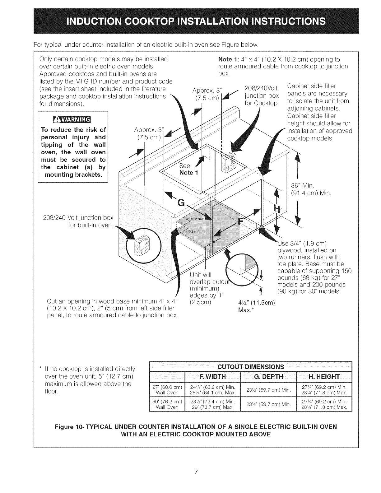
Fortypicalundercounterinstallationofanelectricbuilt-inovenseeFigurebelow.
Onlycertaincooktopmodelsmaybeinstalled
overcertainbuilt-inelectricovenmodels.
Approvedcooktopsandbuilt-inovensare
listedbytheMFGIDnumberandproductcode
(seetheinsertsheetincludedintheliterature
packageandcooktopinstallationinstructions
fordimensions).
To reduce the risk of
personal injury and
tipping of the wall
oven, the wall oven
must be secured to
the cabinet (s) by
mounting brackets.
208/240 Volt junction box
for built-in
Approx. 3"
(7.5 cm)
Approx. 3"
Note 1
(7.5 cm)
Note 1: 4" x 4" (10.2 X 10.2 cm) opening to
route armoured cable from cooktop to junction
box.
208/240Volt
junction box
for Cooktop
Cabinet side filler
panels are necessary
to isolate the unit from
adjoining cabinets.
Cabinet side filler
height should allow for
installation of approved
cooktop models
36" Min.
(91.4 cm) Min.
Cut an opening in wood base minimum 4" x 4"
(10.2 X 10.2 cm), 2" (5 cm) from left side filler
panel, to route armoured cable to junction box.
If no cooktop is installed directly
over the oven unit, 5" (12.7 cm)
maximum is allowed above the
floor.
CUTOUT DIMENSIONS
. F.WIDTH J G. DEPTH. H. HEIGHT
27" (68.6 cm) 247/s' (63.2 cm) Min. 231/2' (59.7 cm) Min. 27_¼' (69.2 cm) Min.
Wall Oven 25_¼' (64.1 cm) Max. 281¼' (71.8 cm) Max.
30" (76.2 cm) 281/2' (72.4 cm) Min. 231/2' (59.7 cm) Min. 27_¼' (69.2 cm) Min.
Wall Oven 29" (73.7 cm) Max. 281¼' (71.8 cm) Max.
Unit will
overlap
(minimum)
edges by 1"
(2.5cm)
3/4" 1.9 cm)
plywood, installed on
two runners, flush with
toe plate. Base must be
capable of supporting 150
pounds (68 kg) for 27"
models and 200 pounds
(90 kg) for 30" models.
4Y2"(11.5cm)
Max.*
Figure 10- TYPICAL UNDER COUNTER INSTALLATION OF A SINGLE ELECTRIC BUILT-IN OVEN
WITH AN ELECTRIC COOKTOP MOUNTED ABOVE
7
Page 8

8
Page 9

Estados Unidos
LAINSTALACIONY ELSERVICIODEBENSEREFECTUADOSPORUNINSTALADORCAUFICADO.
Canada
IIVIPOBTANTE:GUABDEESTASINSTRUCCIONESPABA USO DEL INSPECTOBLOCALDE
ELECTRICIDAD.LEAY GUABDE ESTASINSTBUCCIONES PARAREFEBENCiAFUTUBA.
PARA SU SEGURIDAD: No almacene ni utilice gasolina u otros
vapores y liquidos inflamabies en la proximidad de este o de cuaiquier otro
artefacto.
INFORMACION IMPORTANTE PARA LA INSTALACION
• Todas las estufas electricas funcionan con una alimentaci6n electrica con puesta a tierra de fase singular, 3 o
4 alambres, 240/208 voltios, 60 hertz y s61oAC.
• La distancia minima entre la superficie de la estufa y los gabinetes adyacentes y por encima son de 30" (76.2 cm).
* 30" (76.2 cm) min. paraun i
gabinete desprotegido.
24" (61 cm) rain. para una
NO aplique ningfln sellador
en el perimetro. La unidad
debe respirar libremente.
superficie protegida.
** No obstruya estas _reas.
30" Min. *
(76.2 cm)
Dimensiones
de la Estufa
D
F
Dimensiones del
Recorte
H
i il
Figura 1
308A(78.1) 21Y2(54.6) 287/8(73.3) 20 (50.8) 295/8(75.2)
368A(93.3) 21Y2(54.6) 351A(89.5) 20 (50.8) 357/8(91.1)
Todas las dimensiones se dan en pulgadas (cm).
* Deje 2" (5 cm) de hueco debajo de la estufa para espacio para el cable el6ctrico
y la instalaci6n de la caja de empalmes en la pared detras de la estufa.
Impreso en Canada
9
.4" X 8" (10.2 cm X 20.3 cm)
apertura para el cable si existe
un panel.
298A(75.6) 203/8(51.8) 20Y2(52.1) 4Y2(11.4)
36(91.4) 203/8(51.8) 20Y2(52.1)4Y2(11.4)
P/N 318205412 (1202) Rev. D
English - pages 1-8
Espafiol - pb,ginas 9-16
Franqais - pages 17-24
Page 10

El armario superior no debe sobrepasar una
profundidad maxima de 13" (33 cm)
Min I
30 (76.2 cm) rain. de espaclo _'_._ _ borde_oc/eicorte -_'_----_
entre la parte superior de cubierta -"'-,L_- y el compartimientode
y la parte inferior de un armario de
madera o metalsin protecci6n. _,i
"l
"_.combustible mdts cercano 10"
sobre la parte superior cm)
del armario
18" G
(45.7 cm)
24" (61 cm) min.cuando la parte
inferior del armario de madera o
metal estfi protegida por una placa
cortafuego de al menos 1/8" (0.3
cm), cubierta con una Ifiminade
acero msg noinferior al No.28, de
acero inoxidable de 0.015" (0.4 ram),
aluminio de 0.024"(0.6 ram)o cobre
de 0.020" (0.5 ram).
\
Ubicaci6n aproximada
2 1/2" (6.4 cm) min. desde el
borde delantero del corte hasta
el borde delantero de la parte
superior del armario
Para las letras en este diagrama, refierase a la pagina 9, excepto para J y K.
de la caja de empalmes
J rain. desde el borde
del corte hasta el
compartimiento de
combustible (ambos
lados del artefacto)
No es recomendable utilizar
cajones debajo de la estufa.
Para evitar riesgos de
quemaduras o incendios al tocar superficies
calientes, se deben evitar los armarios sobre
la superficie de los quemadores. Si existe un
armario, se pueden reducir los riesgos instalando
una campana que se extienda horizontalmente
en un minimo de 5" (12.7 cm) por sobre la parte
inferior de los armarios.
Figura 2 - EL CORTE DE LA PARTE SUPERIOR DEL ARMARIO
Ubicaci6n del n_mero de rnodelo y de serie
La placa con el n_mero de modelo y de serie est&
ubicada en el fondo de la estufa.
Cuando haga pedidos de repuestos o solicite
informaci6n con respecto a su estufa, este siempre
seguro de incluir el nQmero de modelo y de serie y
el nQmero o letra del Iote de la placa de serie de su
homo.
30"
36"
La placa de serie
est_ ubicada aqui.
10
2" (5.1cm)
2" (5.1cm)
1 1/2" (3.8cm)
2" (5.1cm)
Page 11

Notas importantes para el instalador
1. Lea todas las instrucciones contenidas en este manual
antes de instalar la estufa.
2. Retire todo el material usado en el empaque de la estufa
antes de conectar el suministro electrico ala estufa.
3. Observe todos los c6digos y reglamentos pertinentes.
4. Deje estas instrucciones con el consumidor.
5. Solamente algunos modelos de cubierta de cocina
pueden set instalados sobre ciertos modelos de homo
de empotre. Las cubiertas y hornos aprobados estan
listados por el n_mero MFG ID y c6digode producto.
(Refierase a la hoja de informaci6n para vet los nOmeros
de modelos).
Nota importante al consumidor
Conserve estas instrucciones y el Manual del usuario
para referencia futura.
INSTRUCClONES IiVlPORTANTES
DE SEGURIDAD
Aseg_rese de que su estufa sea instalada
y puesta a tierra de forma apropiada pot un
instalador calificado o pot un t_cnico de servicio.
= Esta estufa debe set el_ctricamente puesta a
tierra de acuerdo con los c6digos locales o, en
su ausencia, con el C6digo El_ctrico Nacional
ANSI/NFPA No. 70 - _ltima edici6n en los
Estados Unidos.
La alimentaci6n el_ctrica a la estufa
deber& apagarse mientras se hacen las conexiones
de linea. El no harcelo podr{a resultar en daSos
serios o la muerte.
Provea conexi6n electrica
Instale la caja de empalmes debajo del armario y
provea un cable de 120/240 o 120/208 Voltios, AC al
panel de circuitos del aparato. NOTA: NO conecte la
cable al panel de circuitos en este momento.
Requisitos electricos
Cumpla con todos los c6digos en vigor y todos los
reglamentos locales.
1. Para el suministro electrico solamente se necesita
corriente con frecuencia de 60 Hz AC y fase Onica
de 120/240 o 120/208 voltios suministrada por cable
de 3 o de 4 alambres en un circuito separado con
fusibles en ambos lados de la linea (se recomienda
un fusible de tiempo retardado oun cortacircuitos).
NO ponga un fusible en el hilo neutro.
2. Un interruptor oun fusible clasificado en 50
amperios se recomienda (40 amperios minimo).
NOTA: El tamaSo de los cables y de las conexiones
debe de estar en conformidad con el tamaSo del fusible
y con la capacidad del electrodomestico y de acuerdo
con el C6digo Electrico Nacional ANSI/NFPA No. 70 -
01tima edici6n y los c6digos y reglamentos locales.
No se debe usar una extensi6n para
enchufar este electrodom_stico. Esto podria resultar
en un incendio, un choque el_ctrico u otto tipo de
da5o personal.
3. Este electrodomestico debe conectarse a la caja
de fusibles (o de cortacircuitos), por medic de
un cable blindado flexible o un cable con forro no
met&lico. El cable blindado flexible que va desde
el electrodomestico debe de estar conectado
directamente a la caja de empalme. La caja de
empalme debe de estar Iocalizada en el lugar que se
indica en la Figura 2, dejando tanto exceso de cable
como sea posible entre la caja y el electrodomestico,
de forma que asi el electrodomestico se pueda
mover facilmente, si fuera necesario para hacer una
reparaci6n.
4. Se debe de usar un conectador que reduzca la
tirantez de una forma adecuada para unir el cable
blindado flexible a la caja de empalme.
Instrucciones de desempaque
1. Desempaque e inspecte el electrodomestico.
2. Aseg0rese que la botella de limpiador ubicada
en la empaquete de literatura esta situada en un
lugar donde puede encontrarse f&cilmente. Es
importante de tratar de antemano la superficie en
vidrio de cer&mico antes de utilizar. Ve a la parte
sobre Limpieza y Mantenimiento de la Cubierta
en este Manual del usuario.
Cone×i6n EI6ctrica
Conecte el cable blindado flexible que se extiende
desde la superficie del artefacto hasta la caja de
empalmes el retenector utilizando de tensi6n adecuada
en el punto en que el cable blindado entra en la caja
de empalmes. Realizar luego la conexi6n electrica de
la siguiente manera.
En este electrodomestico se necesita un cable de
puesta a tierra.
Este electrodom_stico viene
equipado con un cable de conexi6n de cobre.
Si esto tuviera que conectarse a los cables de
aluminio de una casa, use solamente los conectores
especiales aprobados para empalmes de cobre
y aluminio, de acuerdo con el C6digo El_ctrico
Nacional y los reglamentos y c6digos locales. Una
conexi6n incorrecta del alambrado de aluminio
con los conductores de cobre puede resultar en un
cortacircuito o incendio.
Este electrodomestico se fabrica con un alambre de
puesta a tierra verde (o de cobre sin forro) conectado
con el marco.
NO conecte el alambre puesto
a tierra a una tuber{a de suministro de gas. NO
conecte el suministro de energ{a el_ctrica hasta que
el electrodom_stico haya sido permanentemente
puesto a tierra. Conecte el alambre de puesto
a tierra antes de enchufar pot primera vez el
electrodom_stico.
11
Page 12

Si el cable de la unidad es equipada con 3 alambres:
Donde los c6digos locales permitan conectar el
conductor de puesta a tierra del el_ctrodom_stico
al neutral (blanco) (vet figura 3):
1. Desconecte el suministro electrico.
2. En el interruptor automatico, caja de fusibles o
caja de juntas: conectar el aparato y los cables
residenciales como se muestra en la figura 3.
No podr_ conectar a tierra la
cocina a trav_s del cable neutral (blanco) si la
cocina se usa en una nueva instalaci6n de ramal
de circuito (1996 NEC), en una casa rodante, en
un vehiculo para recreaci6n o si los c6digos
locales no permiten hacer la conexi6n a tierra a
tray,s del cable neutral (blanco).
Cable desde el suministro de energia
blanco (neutral) _ .::::........._L
Alambre _
Alambre _, } _--_
rojos _ : Alambre
" i.........../J ¢--Cajade
Alambre /_ __/// empalmes
verde /
o desnudo J _..... -"-Conductor de
Figura 3 =CAJA DE EMPALMES
DE 3 ALAMBRES PUESTA ATIERRA
Cuando est_ prohibida la conexi6n a tierra a
trav_s del cable neutral (blanco), debe usar un
cable de alimentaci6n de 4 hilos. Vet la Figura 4.
Si no observa esta precauci6n, la persona puede
electrocutarse o lesionarse gravemente.
_-_ uni6n listado-UL
Cable de la estufa
Si la cocina se usa en una instalaci6n nueva de
ramal de circuito (1996 NEC), en una casa rodante,
en un vehiculo para recreaci6n o si los c6digos
locales NO permiten hacer la conexi6n a tierra a
trav_s del cable neutral (blanco) (ver figura 4):
1. Desconecte el suministro electrico.
2. En el interruptor automatico, caja de fusibles o
caja de juntas: conectar el aparato y los cables
residenciales como se muestra en la figura 4.
Cable desde el suministro de energia
Alambre
desnudo
Alambre
rojos
Alambre verde o
desnudo
Cable de la estufa
Figura 4=CAJA DE EMPALMES
DE 4 ALAMBRES PUESTA ATIERRA
Si est_ conectado a un
sistema el_ctrico de 4 alambres, el armaz6n del
electrodom_stico NO TIENE QUE estar conectado
al alambre neutro del sistema el_ctrico de 4
alambres.
NOTA AL ELECTRICISTA: Los conductores de cable
blindados provistos con este artefacto son aprobados
por UL para la conexi6n al alambrado de casa de un
calibre mayor. El aislante de los conductores estb.
calificado para temperaturas m&s altas que las del
alambrado de una casa. La capacidad de corriente
del conductor esta gobernada por la calificaci6n de la
temperatura del aislamiento alrededor del alambre en
vez de solamente el calibre del alambre.
.Alambre blanco
Alambre
negros
Caja de
empalmes
Conductor de
uni6n listado-UL
12
Page 13

Si el cable de la unidad es equipada con 4 alambres:
Donde los cOdigos locales permitan conectar el
conductor de puesta a tierra del el_ctrodom_stico
al neutral (blanco) (ver figura 5):
3. Desc0necte el suministr0 electric0.
2. En el interruptor automatic0, caja de fusibles 0
caja de juntas: conectar el aparato y los cables
residenciales como se muestra en la figura 5.
Cable desde el suministro de energia
Alambre i--.._
blanco ¢-. :::_..-.}."---!._
(neutral) \t[ :::::f_:-_:_-->_:::
rojos IF _/\_
Alambre
..L -Caja de
empalmes
JA_ambre
blanco (neutral)
verde o desnudo _--_
Cable de la estufa
Figura 5 =CAJA DE EMPALMES
DE 3 ALAMEtRES PLIESTA ATIERRA
Este electrodom_stico est_
fabricado con un suministro el_ctrico neutro
blanco y un alambre de cobre conectado al
armazOn. El armazOn esta puesto a tierra pot un
enlace de la cone×iOn a tierra con la cone×i6n del
neutro al final de la Ifnea el_ctrica, si es usado
en los estados unidos una nueva instalaciOn de
circuito de bifurcaciOn (1996 NEC), casa rodante,
vehfculos recreacionales, o donde los cOdigos
locales no permitan poner a tierra mediante el
neutro (blanco) o en Canada, desconectar la
cone×i6n blanca de la verde y utilizar la cone×iOn
a tierra para porter a tierra la unidad de acuerdo a
los cOdigos locales, conectar el neutro al circuito
de bifurcaciOn- conductor neutro de manera usual,
Ver Figura 6. Si su electrodom_stico va a set
conectado a una caja de cone×iOn puesta a tierra
de 3 cables (en los estados unidos solamente),
donde los cOdigos locales permitan conectar el
conductor de porter a tierra=electrodom_stico con
el neutro (blanco) ver Figura 5.
Conductor de union
listado - UL (o CSA)
Si la cocina se usa en una instalaciOn nueva de
ramal de circuito (1996 NEC), en una casa rodante,
en un vehiculo para recreaci6n o si los c6digos
locales NO permiten hacer la conexiOn a tierra a
trav_s del cable neutral (blanco) (ver figura 6):
1. Desconecte el suministro electrico.
2. Separe el alambre verde (o cobre desnudo) y el
alambre blanco del electrodomestico.
3. En el interruptor automatico, caja de fusibles o
caja de juntas: conectar el aparato y los cables
residenciales como se muestra en la figura 6.
Cable desde el suministro de energia
Alambre
desnudo
Alambre
verde o
desnudo
Caja de
empalmes listado-UL (o CSA)
Cable de la estufa
Figure 6 : CAJA DE EMPALMES
DE 4 ALAMEtRES PUESTA ATIERRA
Si est_ conectado a un
sistema el_ctrico de 4 alambres, el armazOn del
electrodom_stico NO TIENE QUE estar conectado
al alarnbre neutro del sistema el_ctrico de 4
alambres.
NOTA AL ELECTFIICISTA" Los conductores de
cable blindados provistos con este artefacto
son aprobados pot UL y CSA para la conexiOn
al alambrado de casa de un calibre mayor. El
aislamiento de los conductores esta calificado para
temperaturas mas altas que las del alambrado de la
casa. La capacidad de corriente del conductor esta
gobernada pot la calificaciOn de la temperatura
del aislamiento alrededor del alambre en vez de
solamente el calibre del alambre.
_ /-Alambre
Alambre
negros
"
LL....<._
Conductor de union
13
Page 14

Instalaci6n de la estufa
1.Visualmente inspeccione la estufa para da_os.
Verifique adem&s que todos los tornillos de la estufa
esten bien ajustados (Figura 7).
Tornillos
Figura 7
,
Instale las mensulas de sosten. Ver Figura 8.
Las m_nsulas de sost_n TIENEN QUE instalarse,
a satisfacci6n de los c6digos locales o, en su
ausencia, con el C6digo El_ctrico Nacional ANSI/
NFPA No. 70==_ltima edici6n (Figura 8).
3. Fije la estufa en el recorte del armario.
Estufa _erficie del amario
No quite los espaciadores en los
hordes de la estufa. Estos espaciadores mantienen
la estufa en el centro del espacio provisto. La
estufa debe estar centrado para evitar una
acumulaci6n excesiva de calor que puede resultar
en da_os por calor o incendio (Figura 9).
4. Fije la cubierta o el soporte usando los tornillos provistos
(vease el cuadro 9).
Espaciadores (8)
Agujero Iocalizado
debajo de la caja de
quemador para fijar el
soporte detenedor.
/
/J
Coloque los soportes
en la unidad como se
muestra.
M_nsulas desost_n (2)
Figura 9
Revisi6n de operaci6n
Consulte el Manual del Usuario para las instrucciones
de funcionamiento.
3aciador
Mensula de sost_n
Figura 8
NOTA: No utilice ninguna sustancia para fijar la estfa
debe poder retirarse para las reparaciones cuando sea
necesario.
No toque el cristal o los elementos de la estufa. Puede
que esten Io suficiente calientes para quemar.
Antes de Ilamar al servicio
Lea la secci6n Lista de Control de Averfas en su
Manual del Usuario. Esto le podrA ahorrar tiempo
y gastos. Esta lista incluye ocurrencias comunes
que no son el resultado de defectos de materiales o
fabricaci6n de este electrodomestico,
Lea la garantia y la informaci6n sobre el servicio en su
Manual del Usuario para obtener el n_mero de telefono
y la direcci6n del servicio.
14
Page 15

Instalaci6n tipica para una estufa el_ctrica encirna de un homo de pared instalado debajo
del rnostrador
SOlo ciertos modelos de tapas de cocina se pueden
instalar sobre ciertos modelos de hornos electricos
empotrados. Las tapas de cocina y los hornos
empotrados se mencionan por su nOmero de
identificaciOn MFG ID y cOdigo de producto (ver la
planilla que se incluye en el paquete de literatura y las
instrucciones de instalaciOn de la cocina donde estan
detalladas las dimensiones). Approx. 3"
Para reducir el
Approx. 3"
guiar el cable blindado de la cubierta a la caja de
conexiones.
riesgo de lesiones
personales
y inclinaci6n
del homo de
pared, _ste debe
asegurarse a los
gabinetes mediante
soportes de
montaje.
208/240 caja de
empalme
hornos de pared
Nota 1: Apertura de 4"x 4" (10.2 x 10.2 cm) para
208/240V caja
de empalme
para la estufa
electrica
Los paneles de relleno
laterales del gabinete son
necesarios para aislar la
unidad de los gabinetes
adyacentes. La altura del
relleno lateral del gabinete
debe permitir la instalaci0n
de modelos de tapas de
cocina aprobados.
36" Min.
(91.4 cm) Min.
Instale contrachapado de 3/4"
(1.9 cm) sobre dos correderas,
nivelado con la parrilla inferior. La
base debe poder sostener 150
libras (68 kg) para los modelos
27"y 200 libras (90 kg) para los
modelos 30".
Corte una abertura de 4"X 4"(10.2 cm X 10.2
cm) (minimo) en el fondo del contrachapado,
a 2" (5 cm) del lado izquierdo del panel
Ilenador, para poder encaminar el cable a la
caja de empalme.
Corte
(minimo)
hasta que
sobre pase
la orilla por
1 pulgada
(2.5cm)
4 1/2" (11.5 cm) Max.*
* Si no se instala ninguna tapa de cocina directamente sobre la unidad del horno, se
permite un espacio maximo de 5" (12,7 cm) sobre el piso.
27"(68.6cm) 247/8"(63.2cm)Min. 231/2"(59.7cm) 271/4"(69.2cm)Min.
Homode pared 251/4"(64.1cm)Max. 281/4"(71.8cm)Max.
30"(76.2cm) 28Y2"(72.4cm)Min. 231/2"(59.7cm) 271/4"(69.2cm)Min.
Homode pared 29"(73.7cm)Max. 281/4"(71.8cm)Max.
INSTALACION TJPICA DEBAJO DE LA MESADA DE HORNO SIMPLE EMPOTRADO
CON TAPA DE COCINA MONTADA
15
Page 16

16
Page 17

I_tats-Unis
UNINSTALLATEURQUALIFII_DOlTEFFECTUERL'INSTALLATIONETLESERVICE.
iMPORTANT: CONSERVEZCES iNSTRUCTiONS POUR LES INSPECTEURS LOCAU×.
LISEZ CES iNSTRUCTiONS ETCONSERVEZ-LES POUR RI_FI_RENCESULTI_RIEURES.
POUR VOTRE Sl':CURITf:: N'entreposez et n'utilisez pas
d'essence ou d'autres produits inflammables & pro×imit_ de cet appareil ou
de tout autre appareil.
INSTRUCTIONS D'INSTALLATION IMPORTANTES
• Toutes les tables de cuisson electriques fonctionnent avec un c_ble a 3 ou 4 fils monophase de 240/208
volts, 60 hertz CA mis a la terre seulement.
Veuillez prendre note que la distance minimale entre la plaque de cuisson et les armoires adjacentes et
en surplomb est de 30" (76.2 cm).
* Minimum de 30" (76.2 cm)
pour armoire non proteg6e.
Minimum de 24" (61 cm)pour
surface proteg6e.
N'APPLIQUEZ AUCUN SCELLANT LE
jLONG DU PERIMETRE. LA TABLE DE
DOlT RESPIRER LIBREMENT.
** Ne bouchez pas ces zones.
30" Min. *
(76.2 cm)
Dimensions de la
table de cuisson
Dimensions de decoupage
pour la table de cuisson
D
C
,Ouverture de 4" X 8" (10.2 cm x
20.3 cm) pour laisser passer le
.......:s:::::---:-;'....[_c_bIe arm 6 s'i I y a un panneau.
i
::Figure 1
211/p(54,6)
211/p(54,6)
Toutes les dimensions sont en pouces (cm).
Laissez un espace de 2" (5 cm) au-dessous de la plaque de cuisson pour d6gager le cg.ble
et faciliter I'installation de la boite de jonction sur le mur a. I'arriere de la plaque de cuisson.
Imprim6 au Canada
3(7,6) 43/8(11,1) 287/8(73,3)
3(7,6) 48/8(11,1) 351A(89,5)
20(50,8) 298/8(75,2) 293A(75,6) 203/6(51,8) 20_f_(52,1) 4_f_(11,4)
20(50,8) 357/8(91,1) 36(91,4) 203/6(51,8) 20_f_(52,1) 4_f_(11,4)
P/N 318205412 (1202) Rev. D
English - pages 1-8
Espa_ol - pages 9-16
Frangais - pages 17-24
Page 18

L'armoiresup@ieurenedoltpasexc6der
uneprofondeurmaximalede13"(33cm).
_-------- A_,Min
D6gagementminimalde30"
(76.2cm)entrelehautdela
surfacedecuissonetlabasede
I'armoireenboisouenm6talnon
prot6g6e.
Minimumde24"(61cm)Iorsque
labasedeI'armoireenboisou
enm6talestprot6g6eparun
cellodermeretardateurdeflammes
d'unminimumde1/8"(0.3cm)
recouvertd'unefeuilledem6tal
MSGNo28,d'acierinoxydable
d'unminimumde0,015(0.4mm),
d'aluminiumde0,024(0.6mm)ou
decuivrede0,020(0.5mm).
* Les lettres sur cette figure
@ferent aux valeurs du tableau
de la page p@cedente sauf pour
J, K et L.
Minimum de 21/2'' (6.4 cm)
du rebord de d6coupage
reco_i_nmtae le k /
le reI_-_r_-re cte-
d6coupage et lemur en
"_ mat6riel combustible le
plus proche du 10"
de comptoir. 25.4 cm)
18" G
(45.7 cm)
au rebord avant du
dessus de comptoir.
Installez la boite de jonction
B.un emplacement qui sera
facile d'acc_s et qui ne nuira
pas _.I'installation de la table
de cuisson. Nous sugg@ons
12" (30.48cm) en dessous du
comptoir.
Minimum de J du
rebord de la plaque
de cuisson au mur
en mat@iel inflam-
mable le plus proche
(de chaque c6t6 de
I'appareil).
II n'est pas recommand6
d'utiliser un tiroir en-
dessous de la table de
cuisson. L'espace libre est
requis pour les besoins
d'installation.
Pour eliminer les risques de br01ures
ou de feu en allongeant le bras au-dessus des surfaces
de cuisson chaudes, evitez d'installer des armoires
au-dessus de la plaque de cuisson. Si vous devez en
installer, il est possible de @duire le risque en placant
une hotte pour cuisiniere qui excede horizontalement d'un
minimum de 5" (12.7 cm) la base de I'armoire.
Figure 2 - OUVERTURE DE DECOUPAGE DU COMPTOIR
Emplacement des num_ros de modele et
de s_rie
La plaque signaletique o0 se trouvent les numeros
de modele et de serie est situee sous la plaque de
cuisson.
Pour toute commande de pieces ou demande de
renseignements, au sujet de votre table de cuisson,
assurez-vous de toujours inclure les numeros de modele
et de serie, ainsi que le numero ou la lettre du lot de
votre table de cuisson.
18
30"
36"
Emplacement de la
plaque signal_tique
2" (5.1 cm)
2" (5.1 cm)
iii ii!iiiiiiii iii!IUi!!ii
1 1/2" (3.8cm)
2" (5.1 cm)
Page 19

Notes importantes pour I'installateur
1. Lisez toutes ces instructions avant de proceder
I'installation de la table de cuisson.
2. Enlevez tout le mat@iel d'emballage avant de
proceder au raccordement electrique.
3. Observez tous les codes et @glements applicables.
4. Assurez-vous de laisser ces instructions au
consommateur.
5. Seulement certains modeles de tables de cuisson
peuvent Ctre installes au-dessus de certains modeles
de fours a encastrer. Les tables de cuisson et les
fours a encastrer approuves sont identifies par le
num@o MFG ID et le code de produit.
Notes importantes pour le consommateur
Conservez ces instructions avec votre Guide de
I'utilisateur pour @ferences futures.
N'utilisez pas de rallonge
_lectrique avec cet appareil. Son utilisation peut
causer un feu, un choc _lectrique ou des blessures
corporelles.
3. II faut brancher I'appareil au panneau de
distribution en utilisant des c_bles flexibles
gaine metallique ou non metallique. On dolt
brancher directement a la boite de jonction le
c_ble gaine flexible de I'appareil. II faut installer
la boite de jonction tel qu'illust@ a la Figure 2
en laissant autant de I_che que possible dans le
c_ble entre la boite et I'appareil, pour en faciliter le
deplacement si I'entretien s'avere necessaire.
4. Une Iongueur de c_ble suffisante dolt Ctre p@vue
pour permettre une connexion du c_ble gaine
flexible a la boite de jonction.
DIRECTIVES
IMPORTANTES DE
SECURiTE
• Assurez-vous que votre appareil est install_ et mis
la terre correctement par un installateur ou un
technicien de service qualifi_.
• Cet appareil doit _tre mis & la terre conform_ment
aux codes Iocaux d'_lectricit_ ou, en I'absence de
codes, en conformit_ avec le National Electrical
Code ANSI/NFPA No.70=Derni_re _dition aux I_tats=
Unis ou avec le CSA Standard C22.1, Canadian
Electrical Code, Part 1, au Canada.
II faut couper I'alimentation
_lectrique durant le branchement _lectrique. A
d_faut de ce faire il peut en r_suiter des blessures
graves ou la mort.
Connexion electrique
Installez une boite de jonction sous I'armoire reliee
un circuit de 240V ou 208V. NOTE: NE branchez PAS
maintenant les c_bles de I'appareil au panneau de
distribution electrique.
Exigences electriques
Observez tous les r_glements et les codes Iocaux
applicables.
1. Un c_ble electrique a 3 fils ou 4 fils monophase
120/240V ou 120/208V, 60Hz AC est requis sur
un circuit sepa@ muni d'un fusible sur chaque
fil conducteur (fusible temporise ou disjoncteur
recommande). NE RELIEZ pas de fusible au neutre.
2. Un disjoncteur ou un fusible de 50 Amperes est
recommande (40 Amperes minimum).
NOTE: Le calibre des fils et leurs connexions doivent
Ctre conformes a la capacite des fusibles eta la
capacite nominale de I'appareil, scion le National
Electrical Code ANSI/NFPA No.70-Derniere edition aux
@tats-Unis ou avec le CSA Standard C22.1, Canadian
Electrical Code, Part 1, au Canada.
Instructions de dGballage
1. Deballez et inspectez visuellement I'appareil.
2. Assurez-vous de laisser a vue d'oeil la bouteille de
c@me nettoyante qui se trouve dans I'enveloppe
de litterature. II est important que la surface
vitroc@amique lisse soit p@-traitee avant d'etre
utilisee. Voir la section Soins et Maintenance de
I'appareil dans votre Guide de I'utilisateur.
Connexions _lectriques
Branchez le c_ble flexible arme de I'appareil a la boite
de jonction a I'aide d'une bague anti-traction appropriee
I'endroit ou le c_ble arme penetre dans la boite de
jonction. Procedez alors comme suit avec la connexion
electrique.
La raise _ la terre de cet appareil est requise.
Cet appareil est muni d'un
c&ble conducteur flexible avec fils en cuivre. Si
la connexion est faite _ un filage r_sidentiel en
aluminium, utilisez seulement des connecteurs
sp_ciaux approuv_s pour le raccord de ills en
cuivre & des fiis en aiuminium conform_ment
au code national d'_iectricit6 et aux codes et
ordonnances Iocaux. Le raccordement inexact d'un
c&ble _iectrique d'aluminium aux fils de cuivre peut
avoir pour consequence un court-circuit ou un feu.
Suivez le proc_d_ recommand_ par le fabricant.
Cet appareil est fabrique avec un c_ble d'alimentation
possedant un fil de mise a la terre vert (ou de cuivre
denude) re% au chassis.
NE PAS utiliser un tuyau _ gaz
pour la raise _ la terre. NE PAS raccorder I'appareil
tant que sa raise _ la terre n'est pas compl_t_e.
Raccordez les fils de raise _ la terre avant de mettre
I'appareii sous tension _lectrique.
19
Page 20

Si le c_ble de rappareil est muni de 3 fils:
O_ les codes Iocaux permettent de brancher le
conducteur de raise & la terre de I'appareil au fil
neutre (blanc) (voir la figure 3):
3 Debrancher I'alimentati0n
2. Dans le disjoncteur, boite de fusibles ou boite
de jonction: connecter I'appareil au cable
d'alimentation comme montre a la figure 3.
Vous ne pouvez pas faire
la raise _ la terre de I'appareil par le fil neutre
(blanc) si I'appareil est utilis_ darts une nouvelle
installation de circuit branch_ (1996 NEC),
maison mobile, v_hicule r_cr_atif, ou o_ les
codes Iocau× ne permettent pas la raise & la terre
_ar le fil neutre (blanc).
Cable d'alimentation
Fil Blanc
(neutre)
Fils
rouges
Fils
,irs
Boite de
jonction
Fil vert (mise a la
terre)
homologue-
Cable de U.L. (CSA)
I'appareil
Figure 3 =Bo_te de jonction _ 3 fils
raise & la terre
Quand la raise _ la terre par le fil neutre
(blanc) est interdite, vous deve7 utiliser un
c_ble d'alimentation _ 4 fils. Voir la figure 4. Ne
pas suivre cet avertissement peut avoir pour
r_sultat I'_lectrocution ou d'autres blessures
personnelles s_rieuses.
Si la table de cuisson est utilis_e darts une
nouvelle installation de circuit branch_ (1996
NEC), maison mobile, v_hicule r_cr_atif, ou o_ les
codes Iocau× ne permettent pas la raise & la terre
par le fil neutre (blanc) (voir figure 4):
1. Debrancher I'alimentation.
2. Dans le disjoncteur, la boite de fusibles ou la
boite de jonction : brancher I'appareil au cable
d'alimentation comme indique a la figure 4.
Cable d'alimentation
Fil de iTitSerr_,d : Fil blanc
L_i_I c_L.,iR,, jonctiode
Fil vert (mise a ic:-/S Connecteur
la terre) >-.... homologue- U.L.
Cable de (CSA)
I'appareil
Figure 4 =Boite de jonction &4 fils
raise _ la terre
Si la connexion a _t_ faite en
utilisant un syst_me _lectrique & 4 fils, le ch&ssis
de I'appareil NE DOlT PAS _tre branch_ au fil
neutre du c_ble _ 4 fils.
NOTE POUR L'f==LECTRICIEN: Le cable gaine
fourni avec cet appareil est homologue par UL
pour connexion a des circuits residentiels de fils de
calibre superieur. La capacite thermique de I'isolant
des cables excede considerablement celle des
circuits residentiels. La transmission du courant
electrique maximum permise des fils du cable est en
fonction de la capacite thermique de la gaine plut0t
que du calibre du fil.
2O
Page 21

Si le c&ble de ra_pareil est muni de 4 fils:
Si les codes Iocaux permettent la connexion du fil
de raise b la terre du chassis au neutre (blanc) (aux
P'==tats-Unisseulement) (volt figure 5):
1. Coupez I'alimentation a la boite de jonction.
2. Dans la botte de jonction:
Raccordez les ills de I'appareil a ceux du circuit
electrique tel que montre a lafigure 5.
Cable d'alimentation
/_ Fils
Fi,srougos-q-
_oirs ]
Si I'appareil est utilis_ dans une maison mobile,
un nouveau branchement (1996 NEC), un v_hicule
r_cr_atif ou si les codes Iocaux N'AUTORISENT PAS
la connexion du conducteur de raise _ la terre du
chassis au neutre (fil blanc), le chassis de I'appareil
NE DOlT PAS _tre branch_ au fil neutre du c_ble _ 4 fils.
(volt la figure 6):
1. Coupez I'alimentation a la boite de jonction.
2. Separez le fil blanc du fil d6nude en cuivre de mise
la terre du cable d'alimentation de rappareil.
3. Dans la botte de jonction:
Raccordez les ills de I'appareil a ceux du circuit
electrique tel que montre a la figure 6.
Cable d'alimentation
Fil
. I_ ----- BoTte de
"_'x jonction
.--J F_IIblanc
FIIdenude
_Connecteur
ou vert _----_
Cable de I'appareil
homologue- U.L.
(ou ACNOR)
Fi.gure 5
BOiTE DE JONCTION A 3 FILS lVlISE._ LATERRE
Cet appareil est fabriqu_ avec un
c_ble d'alimentation muni d'un fil blanc neutre
et d'un fil de raise _ la terre en cuivre branch_
sur le chassis. Si I'appareil est utilis_, aux I_tats-
Unis, dans une maison mobile, un nouveau
branchement (1996 NEC), un v_hicule r_cr_atif ok
les codes Iocaux n'autorisent pas la connexion
du conducteur de raise _ la terre du chassis au
neutre ou au Canada, d_branchez les fils blanc et
vert des autres et utilisez le fil de raise _ la terre
pour mettre _ la terre I'appareil conform_ment aux
codes Iocaux, branchez le conducteur neutre de
mani_re habituelle au circuit neutre voir la figure
6. Si I'appareil dolt _tre branch_ _ un c_bie _ 3 fils
(aux Etats=Unis seulement), ok les codes Iocaux
permettent la connexion du fil de raise _ la terre du
chassis au neutre (blanc). Voir la figure 5.
, -....-........._--_i Fil blanc
rouges __/_
I', " Fils
I
Fil d6nude _-(( _z
ou vert _'_I
_.T.... Con necteur
jonction _L¢ homologue- U.L.
Cable de I'appareil (ou ACNOR)
Figure 6 = BOJTE DE JONCTION ._.4 FILS
MISE _. LATERRE
Si la connexion a _t_ faite en
utilisant un syst_me _lectrique & 4 fils, le ch&ssis
de I'appareil NE DOlT PAS _tre branch_ au fil
neutre du c_ble _ 4 fils.
I_LECTRICIEN: Le cable gaine fourni avec cet
appareil est homologue par UL pour connexion a des
circuits residentiels de ills de calibre superieur. La
capacite thermique de I'isolant des cables excede
considerablement celle des circuits residentiels. La
transmission du courant electrique maximum permise
des ills du cable est en fonction de la capacite
thermique de la gaine plut6t que du calibre du ill.
21
Page 22

Installation de la table de cuisson
1.Verifiez si la table de cuisson est endommagee.
Veillez egalement ace que toutes les vis de la table
de cuisson soient bien settees (Figure 7).
Vis
Figure 7
2.1nstallez les supports de fixation (voir figure 8)
N'enlevez pas les entretoises
ressors sur les rebords de rappareil. Ces entretoises
centrent I'appareil darts I'espace fourni _ cet
effet. L'appareil doit _tre centr_ pour emp@cher
I'accumulation d'exc_s de chaleur pouvant entra_ner
des dommages par la chaleur ou le feu (voir Figure
9).
4. Fixez I'appareil au support de fixation en utilisant
les vis fournies (voir Figure 9).
Trou situ6 sous Entretoise b_
le boitier pour ressorts (8)
fixer le support
de fixation.
• j
i
f •
Les supports de fixation DOIVENT _tre install_s
conform_ment aux codes Iocaux ou, en rabsence
de codes, en conformit_ avec le National Electrical
Code ANSI/NFPA No. 70==Derni_re _dition ou avec le
CSA Standard C22.1 du code _lectrique canadien,
Pattie 1 (Figure 8).
3. Inserez I'appareil dans I'ouverture du comptoir.
Table de cuisson Comptoir
de
nylon
Support de fixation
Figure 8
Centrer les supports
de fixation sur la ligne
centrale de I'ouverture
du comptoir.
_" ;_ Supp01t de fixation
(2)
Figure 9
Verification de fonctionnement
Ref6rez-vous au Manuel d'utilisation pour le mode de
fonctionnement.
Ne touchez pas a la vitre
de I'appareil ou aux el6ments. IIs peuvent Ctre
suffisamment chauds pour causer des brOlures.
Avant d'appeler le service d'entretien
Consultez la liste "Avant d'appeler" et les instructions
d'operation qui se trouvent dans votre Manuel
d'utilisation. Vous sauverez probablement du temps
et de I'argent. La liste contient les incidents ordinaires
ne resultant pas de ddectuosites dans le materiel ou la
fabrication de cet appareil.
Referez-vous au Manuel d'utilisation pour les numeros
de telephone du service apres-vente.
NOTE: N'utilisez pas de p_te a calfeutrage; on dolt
pouvoir deplacer I'appareil si I'entretien s'avere
necessaire.
22
Page 23

L'installationtypiqued'unfourencast@electriquesouslecomptoirestp@senteea lafigure.
Seulementcertainsmodelesdetablesdecuisson
peuvent6treinstallesau-dessusdecertains
modelesdefoursencast@s.Lesmodeles
approuvespour6trecombinessontidentifies
I'aided'unnumeroMGFIDetd'uncodedeproduit
(ConsultezlafeuillequisetrouvedansI'enveloppe
delitteratureainsiquelefeuilletd'instructions
d'installationdelatabledecuissonpourles
dimensions).
Pour r_duire les
risques de blessures
et pour emp_eher
le four encastr_ de
basculer. Utilisez les
supports de fixation
pour retenir le four
encastr_ _ I'armoire,
208/240 Volt, botte
de jonction pour le
four encast@
Decoupez une ouverture de 4"X 4" (10.2cm
X 10.2cm), a 2" (5 cm) du c0te gauche du
plancher pour la sortie du cable arme de
I'appareil vers la boite de jonction.
Approx. 3
(7.5 cm)
Note 1: Decoupez une ouverture de 4"x 4" (10.2cm X
10.2cm) pour la sortie du cable arme vers la boite de
jonction.
L'appareil
chevauche
I'ouverture
de 1" (2.5cm)
minimum de
chaque c0te.
208/240 Volt,
boite de
jonction pour
la plaque de
cuisson
4Y2" (1 1,5 cm)
Max.*
II faut fermer les c0tes
de I'habitacle par des
panneaux de bois pour
isoler I'appareil des
armoires de chaque
c0te. La hauteur de ces
panneaux doit faire en
sorte que I'installation
des modeles de tables
de cuisson au dessus
soit possible.
36" Min.
(91.4 cm) Min.
Utilisez un contre-
plaque de s4"(1.9 cm)
d'epaisseur monte sur
deux solives et a egalit6
avec le coup-de-pied.
La base doit pouvoir
supporter 150 Ibs (68 kg)
pour les modeles 27" et
200 Ibs (90 kg) pour les
modeles 30".
* Si aucune table de cuisson n'est installee au-dessus du four encast@,
un maximum de 5" (12.7cm) a partir du plancher est permis.
DIMENSIONS DE L'OUVERTURE
: ' F. LARGEUR G. PROFONDEUR ' H. HAUTEUR
Four encastr_ 247/8' (63.2cm) Min. 231/2' (59.7cm) Min. 27_¼' (69.2cm) Min.
27" (68.6cm) 251¼' (64.1cm) Max. 281¼' (71.8cm) Max.
Four encastr_ 281/2' (72.4cm) Min. 231/2' (59.7cm) Min. 27_¼' (69.2cm) Min.
30" (76.2cm) 29" (73.7cm) Max. 281¼' (71.8cm) Max.
iNSTALLATION TYPIQUE D'UN FOUR ENCASTRI_ SIMPLE SOUS LE COMPTOIR
AVEC UNE TABLE DE CUISSON I_LECTRIQUE OU ._.GAZ INSTALLI_E PAR=DESSUS
23
Page 24

24
 Loading...