

Page 1
SERVICE MANUAL
DISHWASHERS
DISHWASHERS
NEW STRUCTURE
EVOLUTION «60 cm»
F. S. (Free-Standing)
B. I. (Partially built-in)
F. I. (Fully built-in)
(Basic characteristics)
PRODUCTION -SOLARO- (MI)
© ELECTROLUX ZANUSSI
ELETTRODOMESTICI S.p.A.
Corso Lino Zanussi
Publication no.
I - 33080 Porcia (ITALY)
599 34 01-28
Fax +39 434 394096 991105
EN/SERVICE/FL
Page 2

2
Page 3

CONTENTS
INTRODUCTION Pag. 5 - 6
CHARACTERISTICS 7 - 10
HYDRAULIC CIRCUIT 11 - 26
STRUCTURE OF HYDRAULIC CIRCUIT 12
BASE 12
I W M S 13
WATER FILL 14 - 15
CONTROL OF DRAIN 16
DRAIN 17
WATER SOFTENING 18
REGENERATION SYSTEM 18 - 21
CONDENSATION OF VAPOUR 22 - 24
WATER FILL SAFETY FEATURES 25
TROUBLE-SHOOTING 26 - 29
CHECKING THE COMPONENTS 26
ELECTRICAL CIRCUITS / DIAGRAMS 27 - 29
3
Page 4

PURPOSE OF THIS SERVICE MANUAL
The purpose of this Service Manual is to provide service engineers who are already trained in the repair of
traditional dishwashers with specific technical information relative to the new range of New Structure
dishwashers known as the “EVOLUTION” range.
The structural and hydraulic characteristics, as well as the basic circuitry, are common to all the appliances.
For information relative to specific models - technical characteristics, circuit diagrams, exploded drawings
and parts lists - refer to the SERVICE NOTES issued separately for each model.
4
Page 5

INTRODUCTION
NEW TECHNOLOGY = DISHWASHER DESIGNED USING SOPHISTICATED COMPUTER
TECHNIQUES AND MODERN INDUSTRIAL TECHNOLOGY
RESULT:
The use of massive resources and extensive experience, combined with modern technical and contruction
methods, have made it possible to develop this new range of innov ative appliances which meet the
demands of a market in continuous evolution.
MAIN CHARACTERISTICS
STRUCTURE:
- Modular and convertible, in three versions: Free-Standing, Fully-Built-in, Partially Buily-in (control panel
visible).
- One-piece load-bearing base in sound-absorbing material.
- Two removable side panels.
- Styling flexible according to the various configurations requested.
HYDRAULIC CIRCUIT:
- Newly-designed integrated hydraulic circuit.
- New integrated sump (in the base) designed for simultaneous or alternate washing.
- Softening of regeneration water up to 90°F - 50°D.
- Optimization of regeneration at 5 different levels (10 levels for electronic v ersions).
- Mechanical regulation of regeneration level (via software for electronic models).
ELECTRICAL FEATURES:
- Integrated pump motor with dual-purpose operation (wash and drain).
- External tube-enclosed heating element (connected between the sump and the delivery duct to the
upper spray arm).
- New timers / electronic boards (to optimize performance and consumption).
- Vented drying (Impulse, Active Dry, Turbo Dry).
CONTROL / SAFETY FEATURES
- Detection of washing temperature by thermostats (temperature sensors for electronic models).
- Detection of water level by pressure switch (software control for electronic models).
- Anti-leak systems: Anti-overflow - Anti-flooding - Acquastop.
- Anti-overheating systems: Safety thermostat (Time-out for electronic models).
- Door aperture safety device
- Total functional protection (+ software control for electronic models).
ENVIRONMENT AND OPERATION
- Built entirely using recyclable materials
- Super-silent operation thanks to the use of new materials and construction technologies.
- Simplification of installation and build-in procedures.
- Balanced door with self-adjusting hinges (no manual adjustment required).
- New system for adjustment of rear feet from the front of the appliance (for TOP range built-in models).
SERVICING
- Easy access to the components thanks to the removable side panels and intelligent positioning of the
components.
5
Page 6

NEW STRUCTURE 60cm « EVOLUTION » DISHWASHERS
RANGE: TRADITIONAL TYPE
SERIES FEATURES
BASIC / STANDARD
Version: Functions:
- FREE-STANDING - CAR / TCR (3 / 2 rinses)
- PARTIALLY BUILT-IN - ELECTROMECHANICAL CONTROLS
- FULLY BUILT-IN - 1 / 2 KEYS
- 3 /5 WASHING PROGRAMMES
- 1 / 2 WASHING TEMPERATURES
- VISIBLE HEATING ELEMENT
- IMPULSE DRYING
- 5 LEVELS OF REGENERATION
MEDIUM / DELUXE
Version: Features:
- FREE-STANDING - CAR / TCR (3 / 2 rinses)
- PARTIALLY BUILT-IN - ELECTROMECHANICAL CONTROLS
- FULLY BUILT-IN - 3 / 4 KEYS
- 6 / 9 WASHING PROGRAMMES
- 2 / 3 WASHING TEMPERATURES
- VISIBLE HEATING ELEMENT (1)
- ENCLOSED HEATING ELEMENT (2)
- IMPULSE DRYING (1)
- “ACTIVE DRY” DRYING (2)
- 5 LEVELS OF REGENERATION
BASIC - ITRONIC « LL »
Version: Features:
- FULLY BUILT-IN - TCR
- ELECTRONIC CONTROLS
- 6 KEYS
- 5 WASHING PROGRAMMES
- VARIABLE WASHING TEMPERATURES (NTC)
- VISIBLE HEATING ELEMENT (1)
- ENCLOSED HEATING ELEMENT (2)
- IMPULSE DRYING (1)
- “ACTIVE DRY” DRYING (2)
- 5 LEVELS OF REGENERATION
MEDIUM / DELUXE- ITRONIC « HL »
Version: Features:
- FULLY BUILT-IN - TCR
- ELECTRONIC CONTROLS
- 5 KEYS + DIGIT
- 9 WASHING PROGRAMMES
- DELAYED START OPTION
- VARIABLE WASHING TEMPERATURES (NTC)
- VISIBLE HEATING ELEMENT (1)
- ENCLOSED HEATING ELEMENT (2)
- IMPULSE DRYING (1)
- “ACTIVE DRY” DRYING (2)
- 10 LEVELS OF REGENERATION
6
Page 7
60 EVOLUTION - CHARACTERISTICS
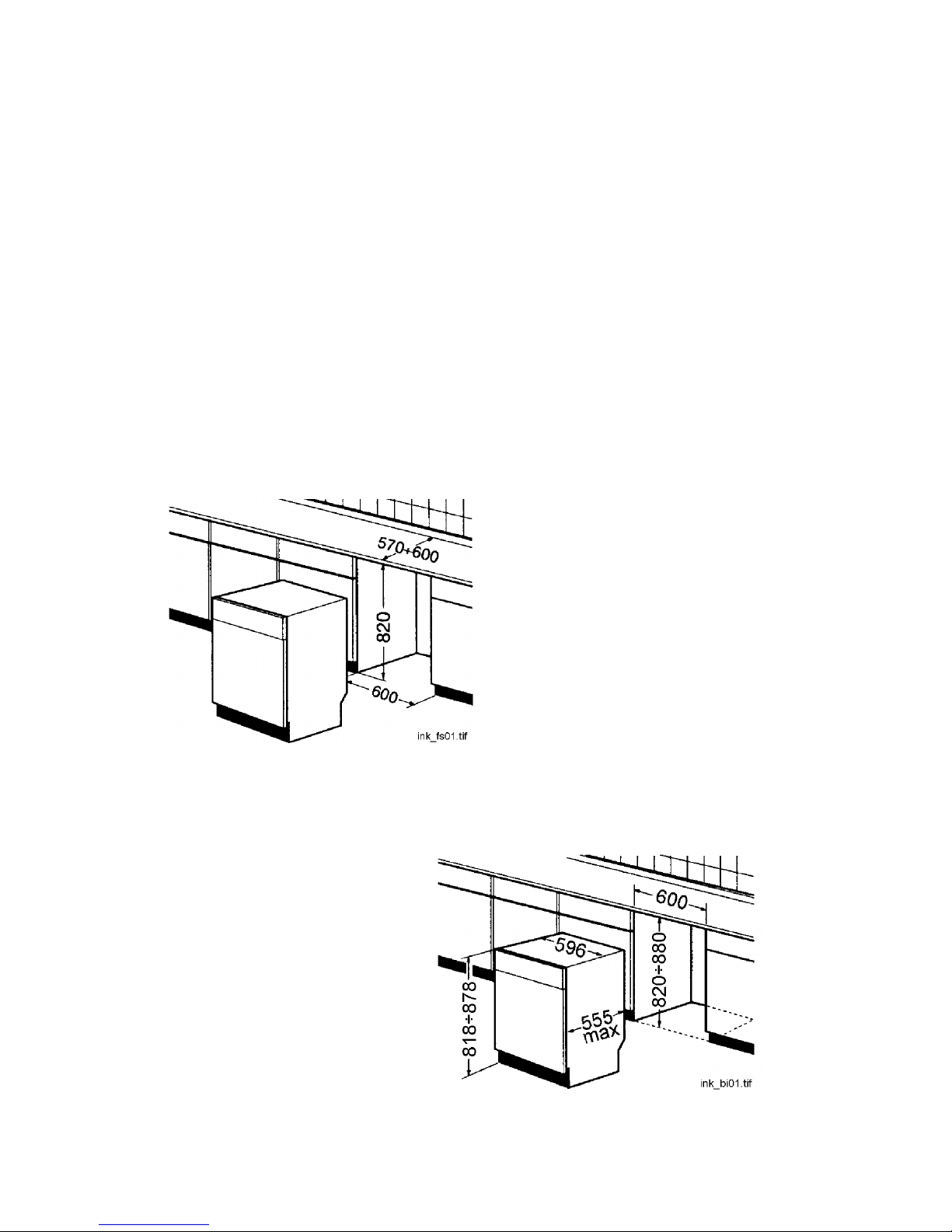
STRUCTURE: 60 cm
CAPACITY: 12 PLACE-SETTINGS
* CONSUMPTION: WATER 22 litres
ENERGY 1.5 KW h
DETERGENT 20 gr
DURATION OF CYCLE 94 minutes
* Data refer to UNIVERSAL cycle
VERSION: FREE STANDING
VERSION: BUILT- IN
7
Page 8
NEW STRUCTURE 60 EVOLUTION - COMPARISON
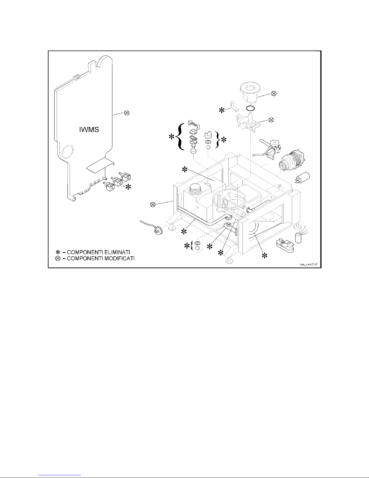
IWMS RESIN WASHING SOLENOID ELIMINATED
INTERNAL DUCTS AND PATHS MODIFIED
BASE RESIN WASHING W ATER CONTAINER ELIMINATED
CONNECTION BETWEEN RESIN WASHING WATER CONTAINER AND SUMP ELIMINATED
SEPARATOR VALVE BETWEEN RESIN WASHING AND SUMP ELIMINATED
CONNECTION BETWEEN WASHING AND DRAIN ELIMINATED
FLOATING VALVE IN RESIN WASHING W ATER CONTAINER ELIMINATED
SEPARATOR VALVE IN BOTTOM OF SUMP (WASHING/DRAIN) ELIMINATED
PERISCOPE ELIMINATED
PUMP CASING MODIFIED (WASHING / DRAIN)
VENTING DUCT MODIFIED
8
Page 9
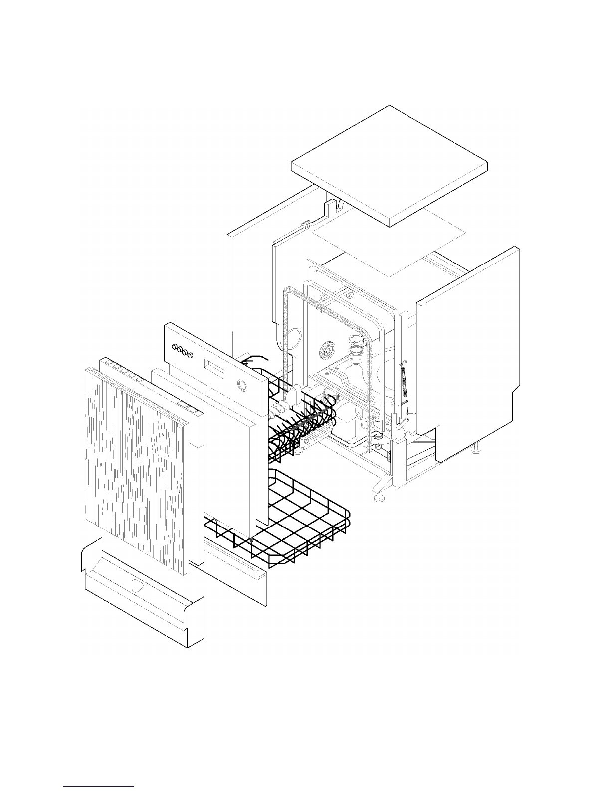
STRUCTURAL CHARACTERISTICS
9
Page 10
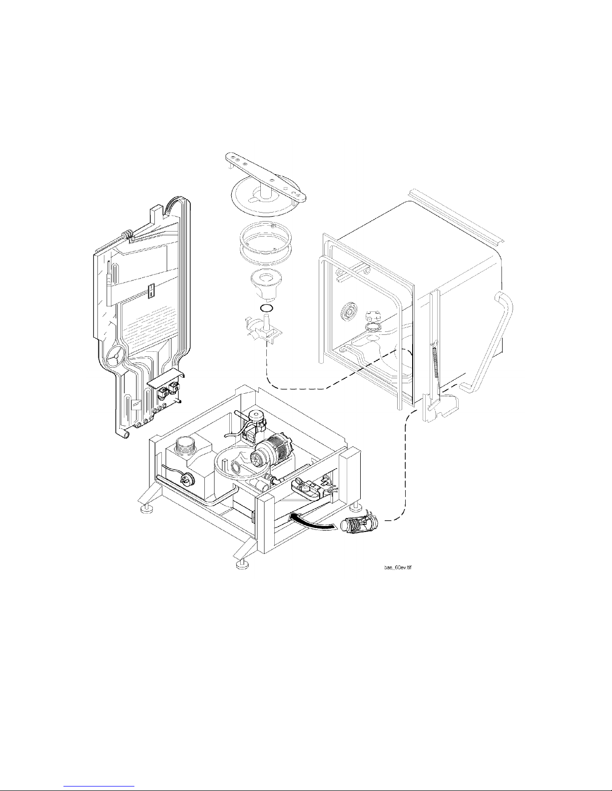
INTERNAL HYDRAULIC/ELECTRICAL CIRCUITS
10
Page 11
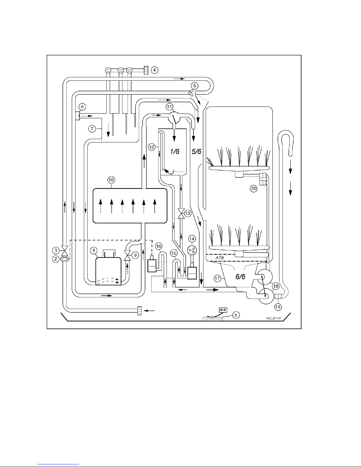
HYDRAULIC CIRCUIT
1. Anti-flooding device 11. Volumetric distributor
2. Anti-overflow device 12. Reservoir for water from volumetric control
3. Fill solenoid 13. Reset solenoid
4. Adjustment of regeneration (manual) 14. Level device (pressure switch)
5. Air-break 15. Level siphon
6. Fill valve for regeneration reservoir 16. Anti-overflow system
7. Reservoir for regeneration water 17. Sump assembly
8. Salt container 18. Washing/drain pump assembly
9. Regeneration solenoid 19. Non-return valve
10. Resin reservoir 20. Delivery valve to upper spray arm
11
Page 12
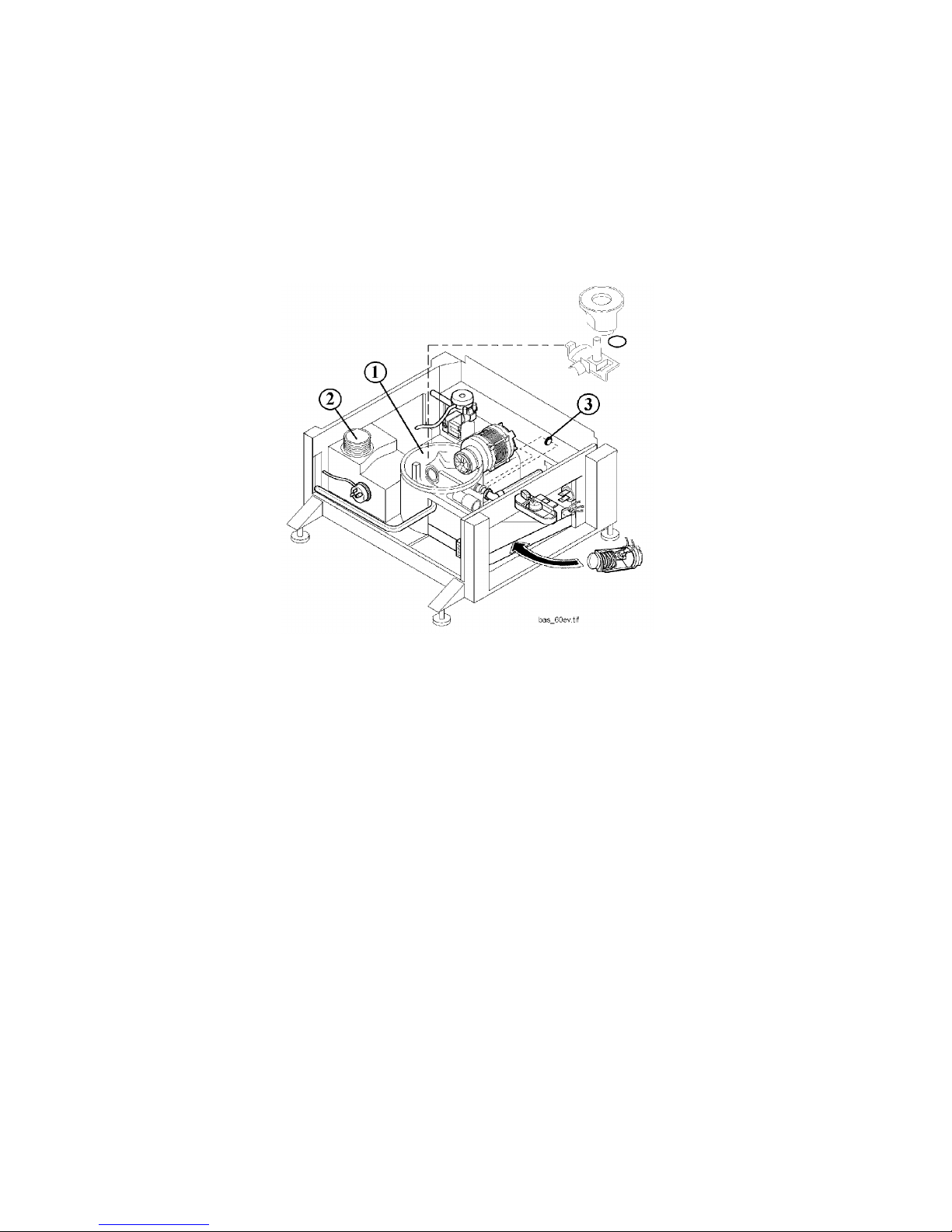
DESCRIPTION OF HYDRAULIC CIRCUIT
The washing system is carried out by two main sections:
- The BASE, designed to contain liquids
- The IWMS water softening system.
BASE
The base is not only the main load-bearing structure of the appliance and of the main functional and
electrrical components, but also houses part of the hydraulic circuit.
THE BASE HOUSES THE FOLLOWING:
1. SUMP ASSEMBLY
The sump is essentially a container fitted with a number of ducts; its function is to collect and distribute
the water to be used to wash the dishes in the appliance.
The sump is connected hydraulically by hoses to the IWMS system and the delivery tubes to the two
spray arms.
The sump also contains components divided into two sections: W ASHING and DRAIN.
WASHING SECTION: Only the water which passes through the large circular filter circulates in this
section. The path is a closed circuit, since once ducted into the sump, the water is pumped by the motor
(washing impeller) to the two rotating spray arms, sprayed onto the dishes, and then returns by gravity
to the filter.
DRAIN SECTION: The drain section receives water containing the residual material removed from the
dishes and ducted through a tangential filter washing nozzle fitted to the lower spray arm. The residue is
trapped in this sector, and is thus prevented from passing into the washing sector.
2. SALT CONTAINER
Contains the salt used for the regeneration process. Connected by a hose to the IWMS.
3. NON-RETURN VALVE (normally closed)
This membrane-type valve is positioned externally on the sump and is connected directly to the drain
hose. Its function is to separate the hydraulic circuit inside the tub from the external section.
Correct operation of the non-return v alve contributes to the final washing result, in that it
- prevents water from outside the appliance (i.e. from the sink, drain siphon etc.) from entering the tub
through the drain hose.
- prevents air from being sucked in through the drain hose, which might create turbulence inside the
sump.
- reduces to a minimum the quantity of water remaining in the sump at the end of each phase of the
cycle.
12
Page 13
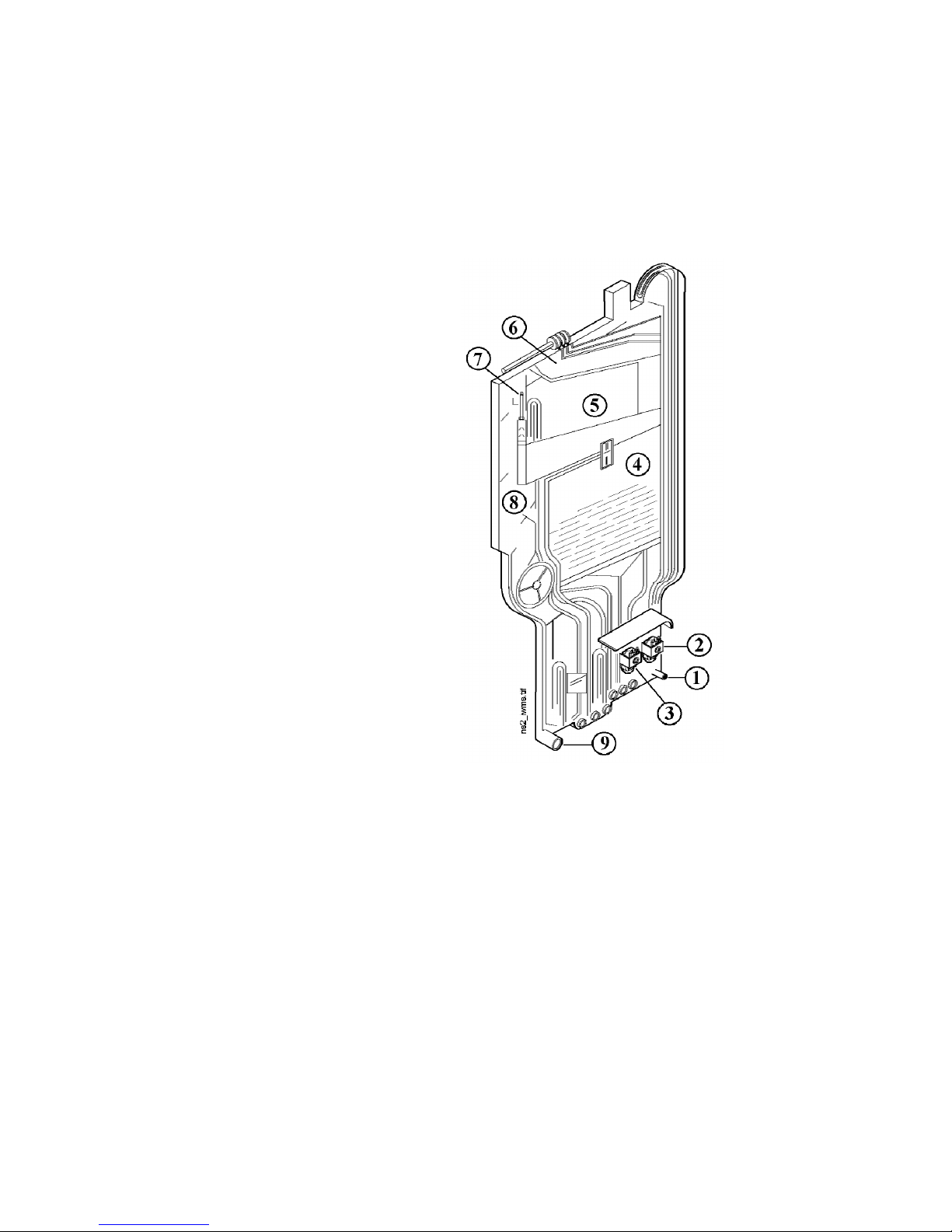
I W M S
Integrated W ater Management System
The external casing in transparent plastic consists of two half-shells that are welded together.
The casing contains the resins (water softening substances) as well as a number of special chambers and
ducts for treatment of the water. These have the following functions:
- WATER FILL CIRCUIT
- WATER FILL CONTROL SYSTEM
- FILL WATER TREATMENT SYSTEM
- REGENERATION SYSTEM
- WATER DRAIN CIRCUIT
- CONDENSATION OF VAPOUR
The following components are built in:
1. INTAKE CIRCUIT FOR FILL WATER
2. REGENERATION SOLENOID
3. RESET SOLENOID
4. RESIN RESERVOIR
5. VOLUMETRIC CONTROL RESERVOIR
6. REGENERATION WATER RESERVOIR
7. VOLUMETRIC DISTRIBUTOR
8. CONDENSATION CHAMBER
9. WATER OUTLET CIRCUIT TO SUMP
The IWMS also contains safety devices for the LEVEL and ANTI-OVERFLOW control functions.
13
Page 14

WATER FILL CIRCUIT
The operating conditions for regular operation of the water fill circuit are as follows:
3. Fill solenoid energized
12. Volumetric control reservoir empty
13. Reset solenoid energized
14. Pressure switch set to “empty” (1 - 2)
PATH OF WATER FILL
From the solenoid valve (3), the fill water passes across the air break (5) and descends through the resin
reservoir (10) and then to the v olumetric distributor (11), where it is subdivided into two parts:
- A small quantity (1/6) of the total quantity of water is ducted into the reservoir of the volumetric control
device (12).
- The remaining water (5/6) passes through the ducts directly into the sump.
1/6 DISTRIBUTION OF W ATER FILL
The water which is ducted into the volumetric control (12), when it reaches the “overflow” level (i.e. full),
activates the internal drain siphon, which ducts the water towards the bottom of the IWMS.
As the water passes through the duct, the flow generates a dynamic pressure in the pressure chamber of
the pressure switch (14); the pressure switch (electrical switching on full 1 - 3) disactivates the solenoid
valve and, at the same time, actions the power loads (motor and heating element), thus allowing the
programme to continue.
At the end of the fill phase, or in any case before the commencement of a subsequent fill phase, the reset
solenoid is (13) activ ated (reservoir reset) in order to ensure that the reservoir of the volumetric control (12)
is completely emptied, since any water remaining in the reservoir may alter the quantity of water for the
subsequent fill.
5/6 DISTRIBUTION OF W ATER FILL
Most of the water (5/6) coming from the volumetric distributor (11) flows into the sump through a single
open duct.
The channel connecting the two parts (IWMS - sump) also permits the following functions:
- Control of the level of water in the tub in order to maintain the level pressure switch actioned.
- Control of excess water level in the tub to action the anti-overflow device.
- Draining of the water during the drain phase in order to reset the devices (level - anti-overflow).
In order to guarantee the reliability of the functional systems, the constant presence of a strong water intake
flow serves to prevent possible blockage of the circuit by keeping the duct clean at all times.
In the section of the circuit between the air-break (5) and the resin reservoir (10), the chambers of the
regeneration reservoir (7) are filled (with natural water) through a calibrated valve (6) according to the
hardness selected by the regulator (4).
14
Page 15
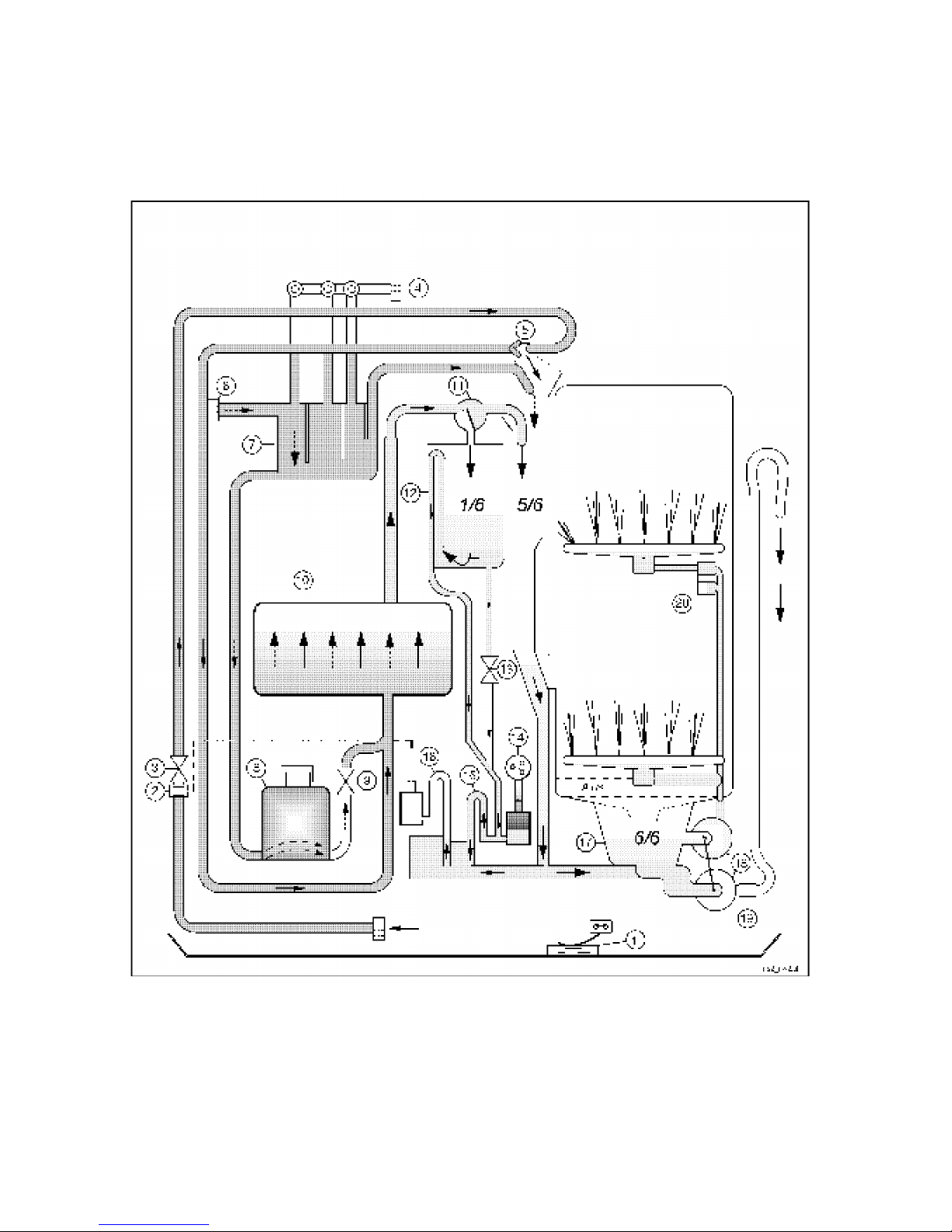
WATER FILL CIRCUIT - FUNCTIONAL DIAGRAM
15
Page 16

WATER FILL CONTROL SYSTEM
This system refers to the path taken by the water inside the IWMS during the fill phase, starting from the
inlet connected to the fill solenoid and passing through the entire internal circuit until it reaches the tub.
The fill control system consists of the following sub-systems:
- VOLUMETRIC CONTROL OF W ATER FILL
- CONTROL OF THE LEVEL OF WATER IN THE TUB
- CONTROL OF THE ANTI-OVERFLOW LEVEL.
VOLUMETRIC WATER CONTROL
This new system provides VOLUMETRIC control (in all phases of the water fill) of the quantity of water
entering the appliance, and is based on a volumetric distributor which ducts a small quantity (1/6) of the
total water fill into a special reservoir.
When the “1/6” reservoir is full, the remaining “5/6” of the water flows into the tub.
The system consists of:
11. Volumetric distributor
12. Volumetric dosing reservoir
12. Drain siphon (inside volumetric reservoir)
13. Reset solenoid (resets the reservoir)
CONTROL OF WATER LEVEL (EMPTY / FULL)
The water lev el is determined by a traditional pressure switch (14) which is connected by a tube to the
coupling on the pressure chamber and positioned at a height such as to monitor both the water in the
volumetric reservoir and the level of the water in the tub.
The signal received from this coupling acts directly on the pressure switch, which switches to “full” (1 - 3),
thus disconnecting the solenoid valve.
Once the level is reached, the pressure switch signal remains “full” (1 - 3), since the lev el siphon (15) is
filled and maintains the pressure in the chamber.
CONTROL OF ANTI-OVERFLOW LEVEL
To the side of the pressure chamber of the pressure switch, at a different height but communicating, a
second pressure chamber is connected to the anti-overflow device (16).
If the level of water in the tub increases, the signal from this coupling directly actions the fill solenoid, and
closes the mechanical part.
16
Page 17
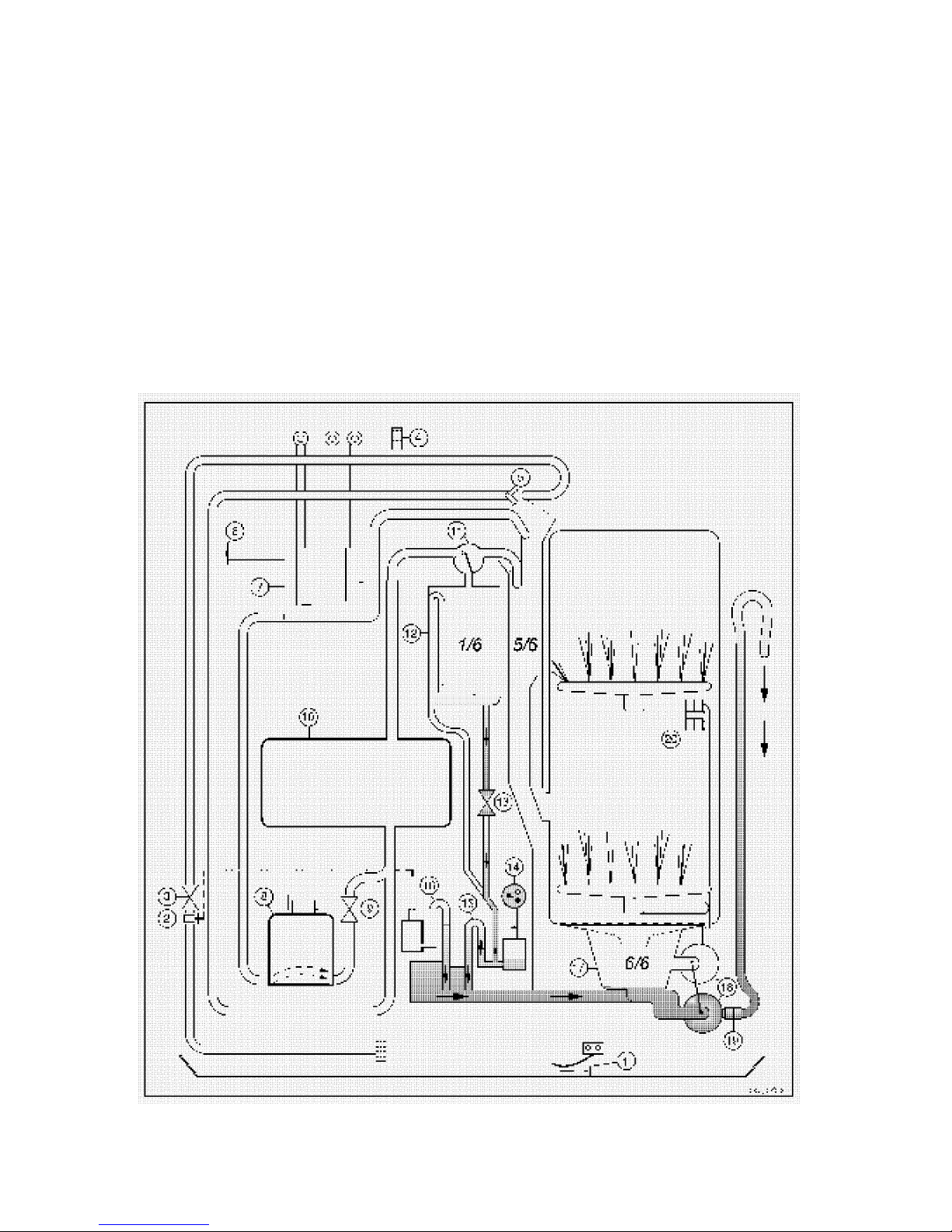
WATER DRAIN CIRCUIT
OPERATION
The motor is actioned in the drain direction in order to drain the water from the sump (17). At the same
time, a vacuum is generated in the IW MS lev el circuit and, via the level siphon (15), empties the pressure
chamber. As a result, the pressure switch (14) switches to “empty” (1 - 2).
If the anti-overflow device (2) is actioned via the siphon (16), this empties the corresponding pressure
chamber and thus disactivates the dev ice.
N.B. It may occur that the anti-overflow device (2) is activated while the fill solenoid is in operation. In this
case, the anti-overflow device (2) has remained in operation while the pressure chamber is empty.
Therefore, in order to disactivate the device, it is necessary to bleed pressure from inside the
solenoid by disconnecting the fill hose connected to the tap.
17
Page 18

WATER SOFTENING SYSTEM
SOFTENING PROCESS
This water softening system utilizes resins (synthetic organic substances) in a chemical ion-exchange
process.
The exchange process takes place rapidly: as soon as the water comes into contact with the resins, the
exchange process beings. The calcium and magnesium contained in the water are removed, while the
resins provide sodium.
This exchange process takes place during every fill cycle, i.e. each time water is ducted into the circuit by
the solenoid valve.
SOFTENING CIRCUIT
The water arriving from the solenoid valve is ducted to the resin container (10). Passing slowly upwards
through the resin bed, the water is softened and then ducted to the volumetric distributor (11) and then into
the tub.
After a time, the softening capacity of the resins naturally decreases, since, having become saturated with
calcium and magnesium, they are no longer able to perform the sodium exchange process. It is therefore
necessary to “regenerate” the resins by introducing sodium chloride.
REGENERATION PROCESS
In order to regenerate the resins and to restore their effectiv eness, it is necessary to add salt (sodium
chloride); the salt solution should be passed gradually through the resins or, preferably, allowed to deposit
for a period.
In this case, too, an ion exchange process takes place. The sodium in the salt solution eliminates the
calcium and magnesium deposited in the resins, which thus re-acquire their softening properties.
The regeneration phase takes place at a predetermined point in the washing cycle and the regeneration
solenoid is actioned for a programmed time.
The quantity of water used, and the amount of salt, are optimized according to the level of regeneration
selected and the degree of hardness of the mains water supply.
After regeneration, it is necessary to clean the softening circuit by washing the resins, which removes any
residual impurities.
RESIN WASHING
The process continues as follows: the water from the resins, which at this stage contains calcium,
magnesium and sodium chloride, must be drained before the subsequent fill phase, so that it does not
come into contact with the dishes or, even more important, the internal parts of the dishwasher. This is
because the water is corrosive.
In this case, too, at a predetermined point in the wash cycle, the fill solenoid and the motor (in the “drain”
direction) are actioned simultaneously to circulate and, at the same time, to drain a certain quantity of water
which rinses out the softening circuit.
18
Page 19
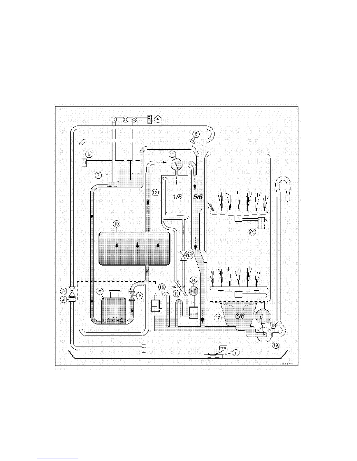
REGENERATION CIRCUIT
When the regeneration solenoid (9) is powered electrically, the water contained in the regeneration
reservoir (7) descends by gravity into the salt reservoir (8) (located in the base of the appliance). Passing
through the salt reservoir, the water removes a given quantity of salty water, which then rises through the
resin bed (11) and passes to the volumetric reservoir (11) and then into the tub.
19
Page 20
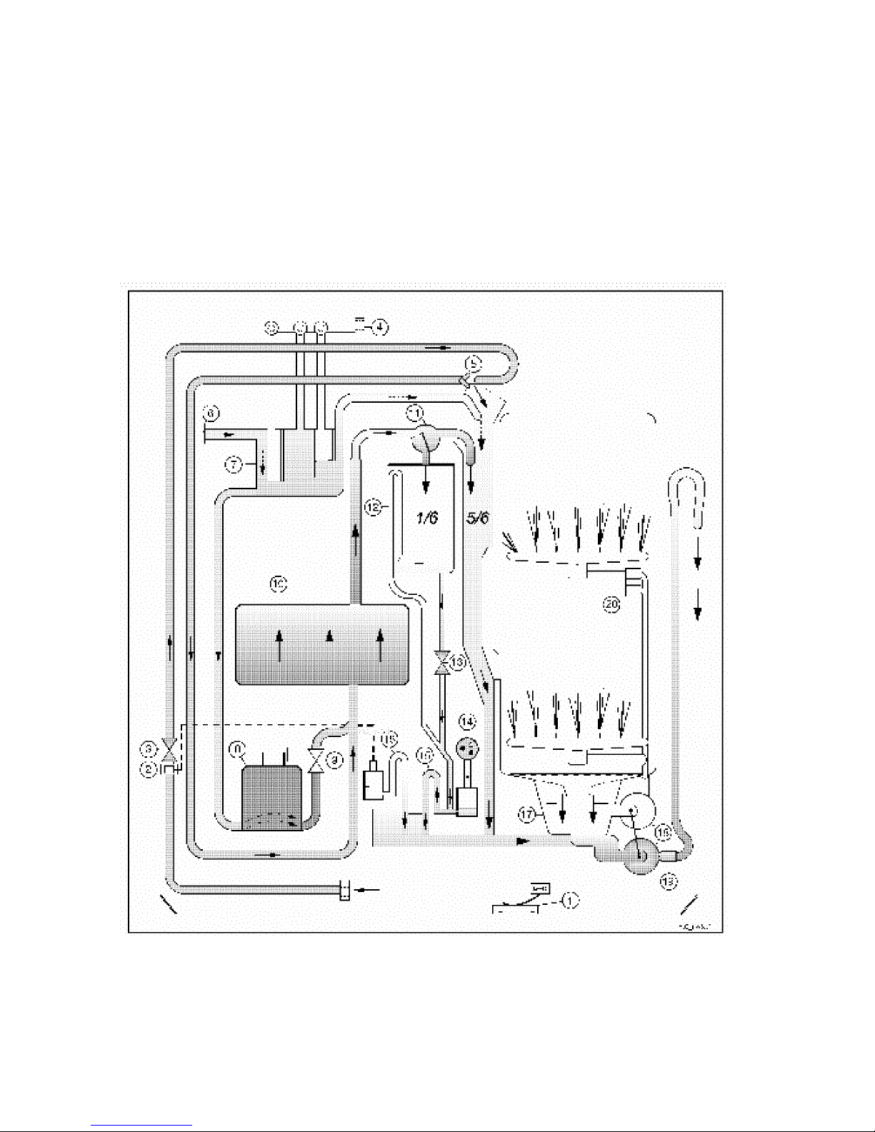
RESIN WASHING
When the fill solenoid (3) is powered electrically, plain water circulates through the resin reservoir (10),
passing through the fill circuit until it reaches the bottom of the sump. In effect, the water follows the same
path described in “W ater Fill Circuit” (page 14).
At the same time, the motor (18) is actioned in the drain direction, and drains off the water as it arrives.
The reset solenoid (13), too, is actioned to reset the reservoir, thus ensuring that the volumetric control
reservoir (12) is drained of any residual water remaining after this phase.
20
Page 21
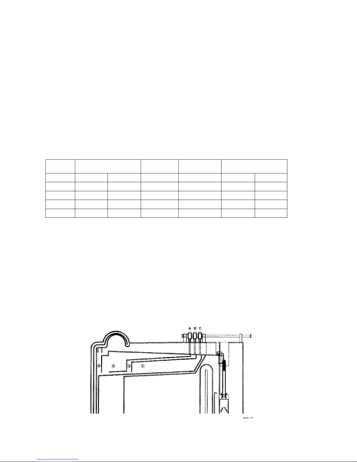
REGENERATION VOLUMES
Four volumes of water are used for regeneration, for a total of approximately 230 CC.
The procedures for regulation of regeneration and the regeneration process itself differ according to the
type of dishwasher (Electromechanical, Itronic, Electronic).
N.B. For Itronic and Electronic dishwashers, the procedures for regulation of the regeneration level are
described in the specific Service Manuals.
DISHWASHERS WITH ELECTROMECHANICAL CONTROL SYSTEMS
Regeneration is performed during each washing cycle.
REGULATION OF THE REGENERATION LEVEL
These dishwashers feature five levels of regeneration, with variable quantities of water controlled by the
aperture or closure of a series of special v alves.
The level of regeneration is selected by turning the 5-position selector knob (positioned in the upper
left-hand corner of the front panel) to the corresponding level.
LEVEL
Nº
HARDNESS
°F / °D
WATER
UTILIZED
SALT
CONSUMPTION
VALVES
CLOSED / OPEN
1.00
08 - 20 04 - 11 35cc 15gr A/B/C --
* 2
21 - 40 12 - 22 70cc 25gr A/C B
3.00
41 - 60 23 - 33 110cc 40gr B/C A
4.00
61 - 80 34 - 45 210cc 65gr B A/C
5.00
81 - 90 46 - 50 230cc 75gr -- A/B/C
The appliance is set in the factory to regeneration lev el 2.
REGENERATION RESERVOIR: FUNCTIONAL DESCRIPTION
DISHWASHERS WITH MANUAL REGULATION:
- Regulation valves A-B-C are connected to the corresponding dosing chambers (a-b-c); chamber d is
independent (i.e. cannot be regulated), and is always filled.
- The valves are opened or closed manually according to the selected level of regeneration.
- W hen a valve is open, the corresponding dosing chamber fills.
- W hen a valve is closed, the corresponding dosing chamber remains empty.
- W hen the regeneration solenoid is actioned (120 seconds), the chambers are drained completely.
21
Page 22
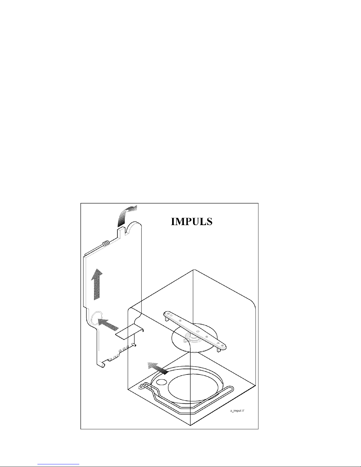
VAPOUR CONDENSATION CIRCUIT
Inside the IWMS, a special chamber, which communicates directly with the inside of the tub, allows the
appliance to dry the dishes by condensing the steam.
The type of drying depends on the type of dishwasher. Three drying systems are used:
- “IMPULSE” DRYING
- “ACTIVE” DRYING
- “TURBO” DRYING
“IMPULSE” DRYING
Description of the system:
This type of drying system consists of an integrated circuit which expels the air from the appliance. This is
the classic drying system combined with natural hot air circulation which is maintained for the entire drying
cycle by pulse actioning of the heating element.
The vapour (hot, humid air) produced during the hot rinse enters the IW MS through the vapour duct in the
lower section; the air circulates through the IW MS where it is condensed and then expelled - after removal
of the humidity - from the upper section
The time for the drying phase is about 10 - 11 minutes, during which the heating element is actioned at
intervals for two different periods (30 and 45 seconds).
22
Page 23
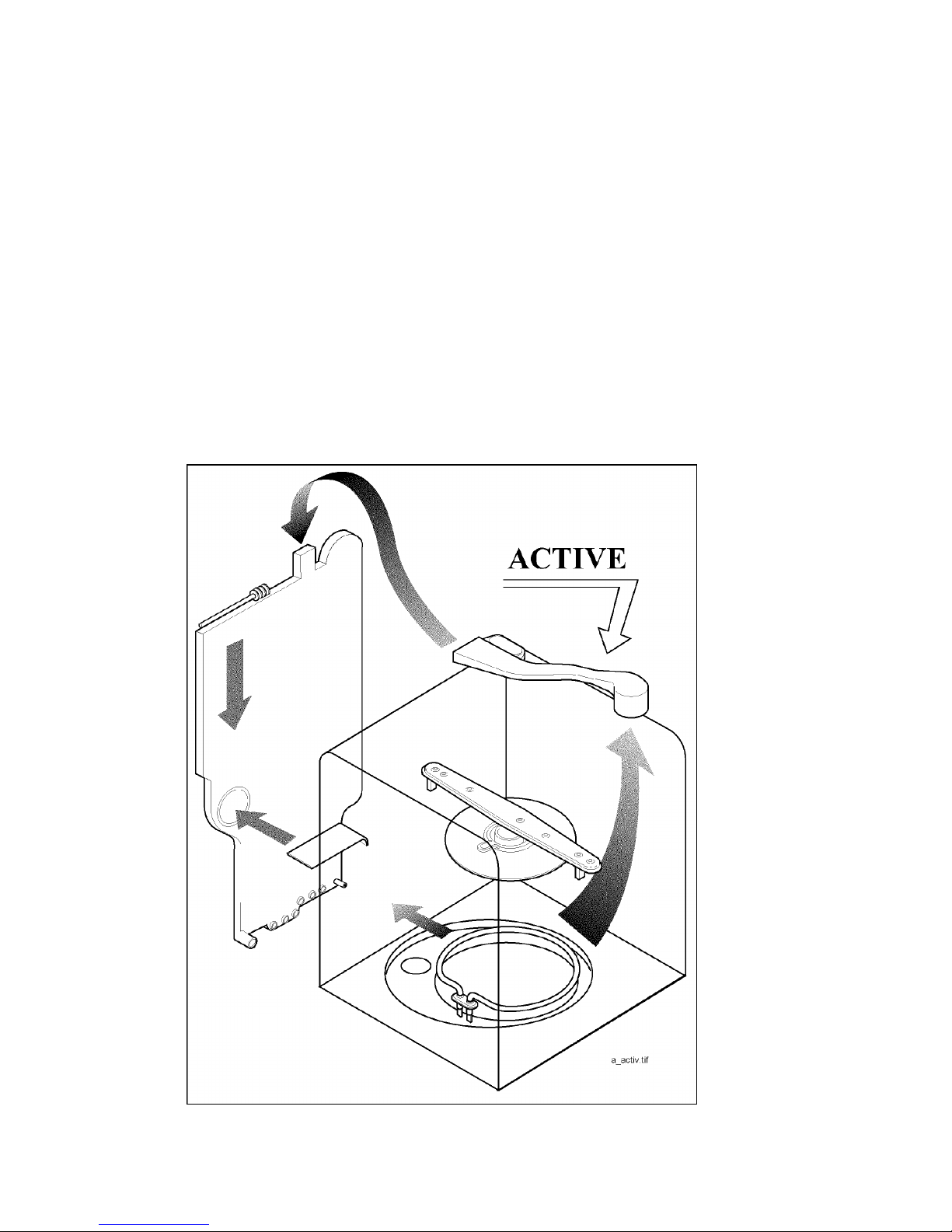
“ACTIVE DRY” DRYING
Description of the system:
This is a new internal drying system based on natural circulation through a duct fitted externally to the
ceiling of the tub and connected to the IWMS.
This integrated circuit does not draw in air from the exterior.
The vapour (hot, humid air) produced during the hot rinse is ducted into the chamber in the IWMS, where it
is condensed in two different circuits.
Part of the vapour passes through the vapour duct in the lower section of the IW MS.
The remaining vapour rises to the top of the appliance and enters the IWMS through the external duct.
This forms a closed condensation circuit which does not expel vapour externally, since it is isolated from
the outside of the appliance.
The time for the drying phase is about 10 - 11 minutes.
23
Page 24
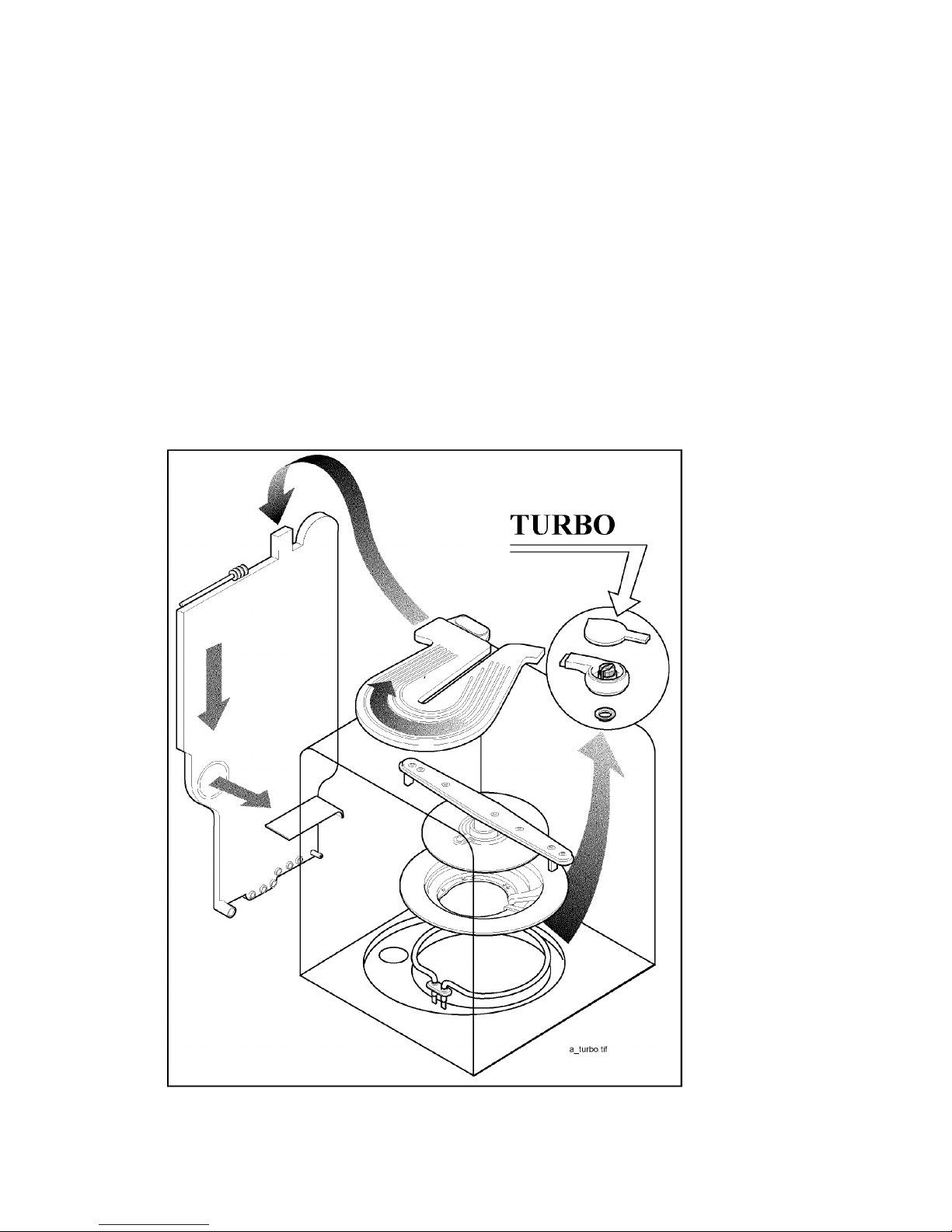
“TURBO” DRYING
Description of the system:
This is a new internal drying system based on forced air circulation provided by a fan fitted externally to the
ceiling of the tub and a duct connected to the IWMS.
The system consists of an integrated circuit which does not draw air into the appliance from the exterior.
The vapour (hot, humid air) produced during the hot rinse is ducted into the chamber of the IWMS where it
is condensed by two separate circuits.
Part of the vapour passes through the vapour duct in the lower section of the IW MS.
The remaining vapour is drawn to the top of the appliance by the fan and enters the chamber of the IWMS
through the external duct.
In this case, the condensation circuit is more effective, since the duct acts as a supplementary chamber.
The time for the drying phase is about 10 - 11 minutes.
24
Page 25
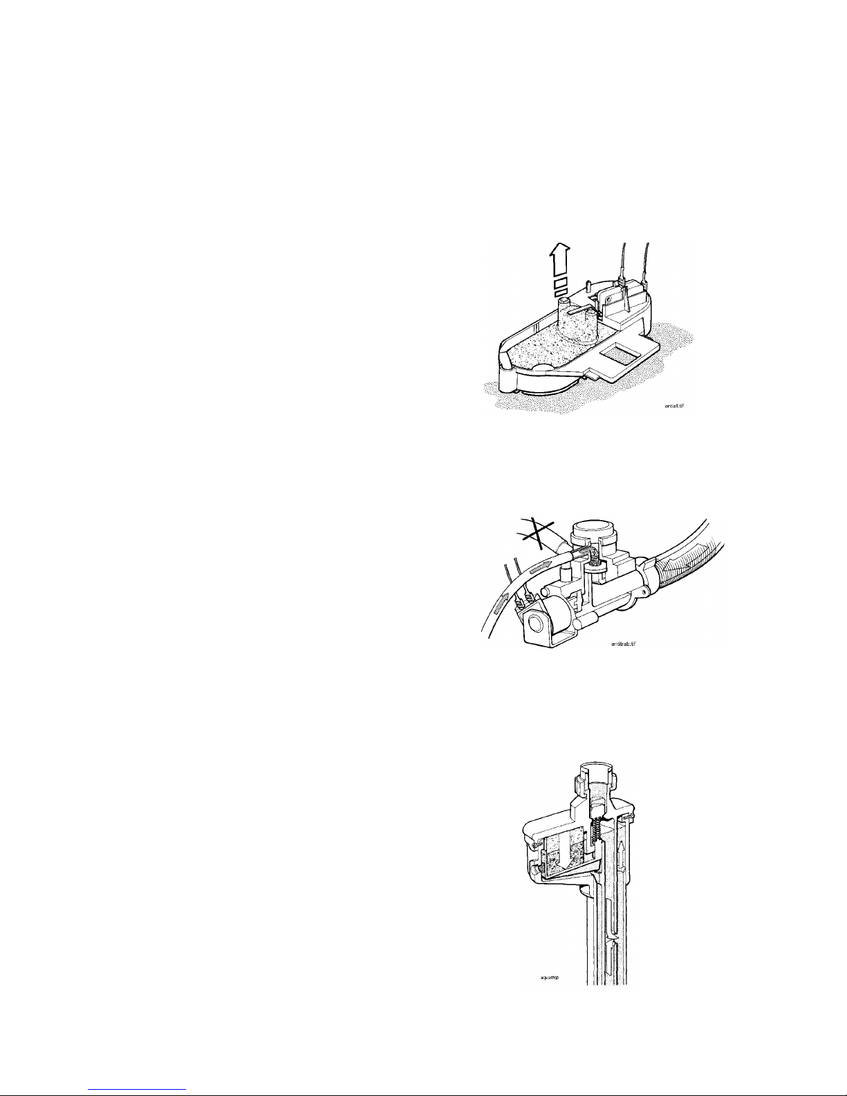
WATER FILL SAFETY SYSTEMS
These safety systems detect any possible malfunctions that might result from incorrect operation of the
hydraulic circuit or leakage from any of the components.
The electromechanical/hydraulic safety devices are always operative during the washing cycle and, in
some cases, even when the appliance is switched off.
These devices are fitted to dishwashers with both Electromechanical and Electronic control systems.
ANTI-FLOODING device
ANTI-OVERFLOW device
ACQUASTOP device
ANTI-FLOODING function
Electromechanical device connected in series to
the solenoid valve.
A floating sensor is housed in the bottom panel
of the machine. The sensor is connected to a
microswitch. When water is present in the
bottom of the tub, the float rises, actioning the
microswitch and disconnecting the solenoid
valve. As a result, the cycle is interrupted.
ANTI-OVERFLOW device
Mechanical device built into the solenoid valve
and connected with the IWMS.
As the level of water in the sump rises, the level
in the anti-overflow chamber of the IWMS, too,
rises, since the two sections are connected by a
tube.
When the water reaches the overflow level, it
flows through the siphon and descends to the
corresponding chamber in the IWMS. This
forces the internal air through the connector
tube, pressurizing the circuit, actioning the
safety device by moving the piston downwards
to block the flow of water.
ACQUASTOP device
Mechanical device built into the drain hose.
This assembly consists of a fill hose at the
extremity of which the device itself is fitted. This
forms an integral assembly, since the two
sections are joined by a hermetic seal which
guarantees perfect water-tightness.
If a leak should occur or if the fill hose should be
damaged, the water is recovered and ducted
through the outer sheath to the inside of the
device. This actions the system, as the sensor
which comes into contact with the water
expends, forcing the valve downwards to block
off the flow of water completely.
25
Page 26
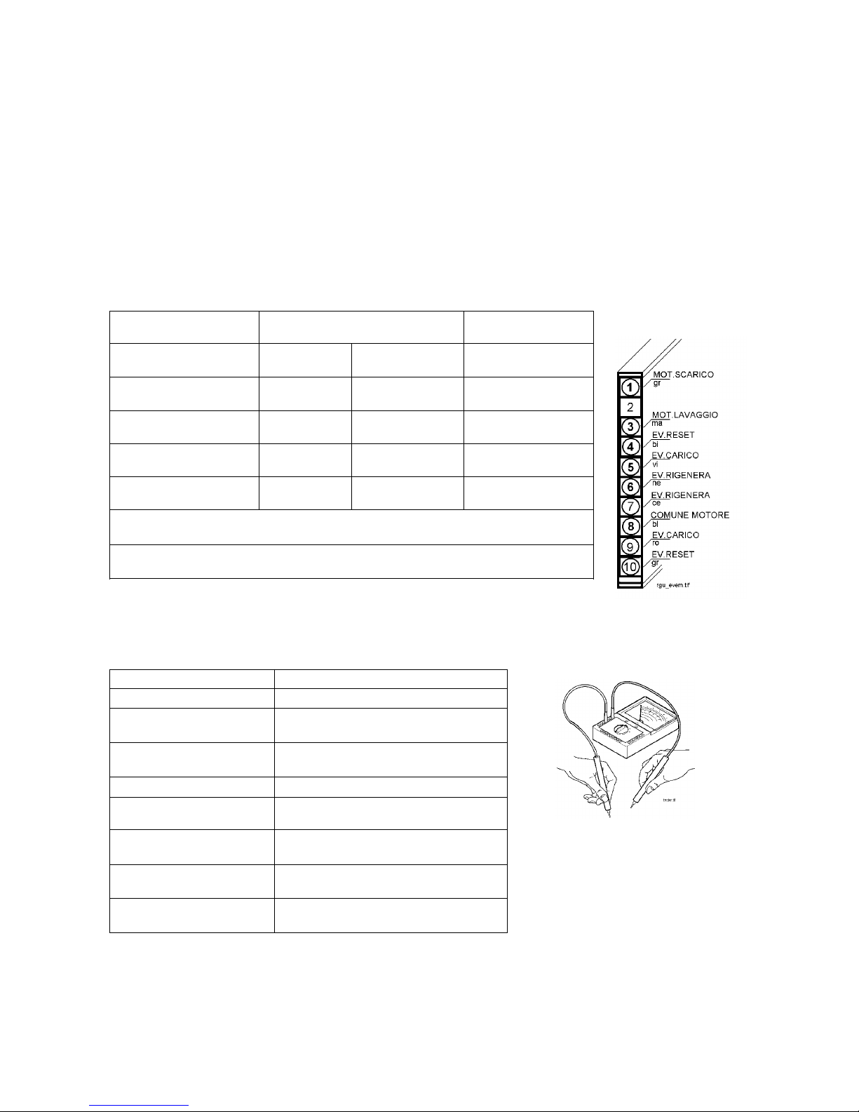
TROUBLESHOOTING
CHECKING THE EFFICIENCY OF THE COMPONENTS
In order to facilitate checking of the efficiency of the component to be tested, a special CONTROL
PROCEDURE has been created. The contacts to which the tester should be applied and the correct
resistance for each component are shown in the table below.
After detaching the modular wiring connector fitted to the bottom of the appliance, measure the resistance
to verify the efficiency of the components fitted to the dishwasher.
TRADITIONAL DISHWASHERS (ELECTROMECHANICAL TIMER)
PROCEDURE: Apply the probes of the tester to the points indicated and measure the resistance.
COMPONENT TESTER PROBES
CONNECTION / COLOUR
CORRECT VALUE
MOTOR
( Drain )
1 - 8
Grey - Blue
73 ΩΩΩΩ ± 7%
MOTOR
( Washing )
3 - 8
Brown - Blue
48 ΩΩΩΩ ± 7%
REGENERATION
SOLENOID
6 - 7
Black - Light blue
5200 ΩΩΩΩ ± 8%
FILL SOLENOID AND
ANTI-FLOODING DEVICE
5 - 9
Purple -Pink
3950 ΩΩΩΩ ± 8%
RESET
SOLENOID
4 - 10
White - Grey
5200 ΩΩΩΩ ± 8%
N.B. If the resistance measured across contacts 1 - 8 and 3 - 8 is the same
(28 ΩΩΩΩ approx.), this means that the capacitor is short-circuited.
KEY: ar = orange bi = white bl = blue ce = light blue gr = grey
ma = brown ne = black ro = pink vi = purple
The remaining components can be tested in the same way or directly on the components themselves.
The correct v alues are listed below:
COMPONENT CORRECT VALUE
DOOR MICROSWITCH
Door closed 0 W
PRESSURE SWITCH
Empty (1-2) INFINITE
Full (1-3) 0 W
HEATING ELEMENT AND
SAFETY THERMOSTAT
2300 W 25 W ± 8%
FAN MOTOR
720 W ± 8%
INTEGRATED DETERGENT
DISPENSER
1300 W ± 8%
TEMPERATURE CONTROL
THERMOSTAT(S)
Open INFINITE
Closed 0 W
SALT SENSOR
With salt INFINITE
Without salt 0 W
RINSE-AID SENSOR
With rinse-aid INFINITE
Without rinse-aid 0 W
26
Page 27
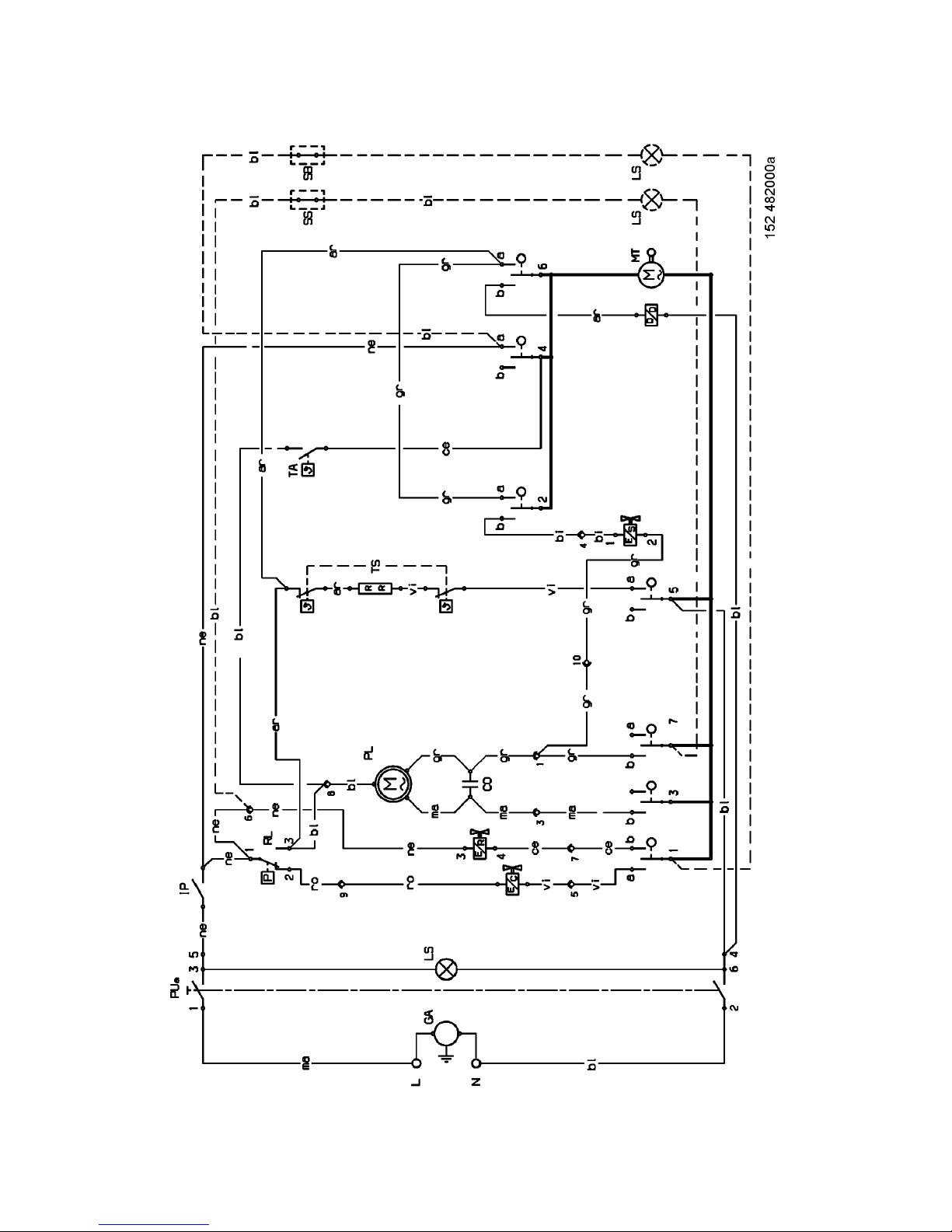
BASIC CIRCUIT DIAGRAM
TIMER 152475400
27
Page 28
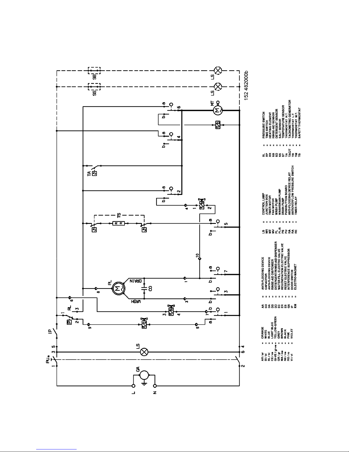
FUNCTIONAL DIAGRAM
TIMER 152475400
28
Page 29
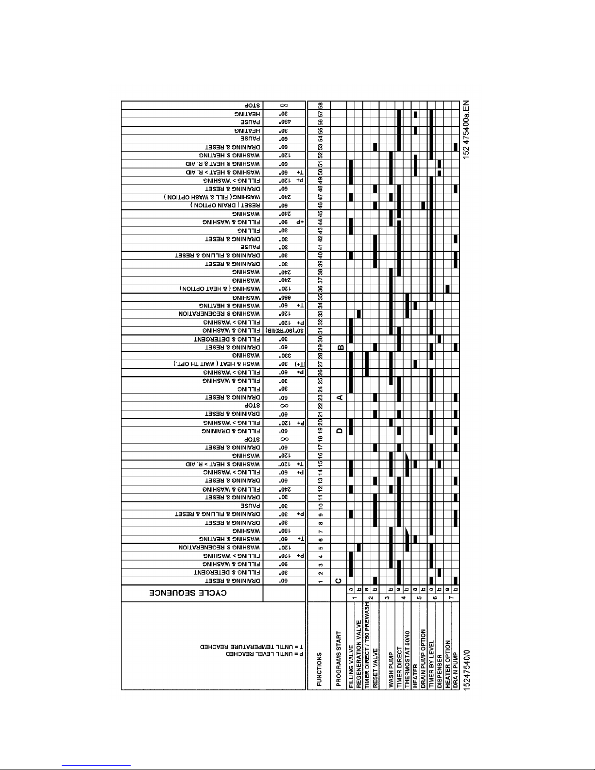
TIMER DIAGRAM
TIMER 152475400
29
 Loading...