

Page 1

ETK7000, ETK8000, ETK7070
ETK8080, ETK7080
Electrolux Refrigeration Trim Kit
Installation Manual
Page 2

2 electrolux.com.au
NOTES
Page 3
3
CONGRATULATIONS
Dear customer,
Congratulations and thank you for choosing our trim kit.
We are sure you will find your new trim kit a pleasure to
use. Before you use the trim kit we recommend that you
read through the relevant sections of this manual, which
provides a description of your trim kit and its functions.
To avoid the risks that are always present when you use an
electric appliance, it is important that the refrigerator and
trim kit are installed correctly and that you read the safety
instructions carefully to avoid misuse and hazards.
We recommend that you keep this instruction booklet
for future reference and pass it on to any future owners.
After unpacking the trim kit, please check it is not
damaged. If in doubt, do not install the trim kit but contact
your local customer care centre.
The symbols you will see in this booklet have these
meanings:
CONTENTS
Trim kit contents (Installation) .....................................4
Trim kit contents (Single refrigerators) ........................5
Trim kit contents (Dual installation only) ......................6
Cabinetry dimensions ................................................8
Single and Dual Installations ....................................10
Joining the refrigerators (Dual installation only) .........11
Installation ...............................................................13
Warranty Information ...............................................19
CAUTION
Be careful when unpacking components. Do not
use sharp objects when removing packaging
material. This may scratch the surface of the trim
components. Take care not to drop the trim kit as
this may damage the components.
WARNING
This symbol indicates information concerning your
personal safety.
CAUTION
This symbol indicates information on how to avoid
damaging the trim kit.
IMPORTANT
This symbol indicates tips and information about
use and installation of the trim kit.
ENVIRONMENT
This symbol indicates tips and information about
economical and ecological use of the trim kit.
CONDITIONS OF USE
This trim kit is designed and intended to be used in normal
domestic applications only.
WARNING
Use extreme care when handling the metal trim
pieces as the corners are very sharp.
• Use only the parts that come with the trim kit for
installation
• Keep ventilation openings in the appliance enclosure
or the built-in structure clear of obstruction.
• Ensure that the floor and surrounding cupboards are
adequately protected from damage during unpacking
and throughout the installation process.
• Ensure that one (two for dual refrigerator installations)
accessible powerpoints are installed before installing
and connecting your appliances. These powerpoints
should also be readily accessible after fridge
installation is completed. Connect the mains plug to
the mains outlet only after the installation is complete.
• Do not use extension leads or power board or double
adapter under any circumstances as it may lead
to electric shock and / or fire. Seek assistance of a
licensed electrician if required.
• Due to size and weight of the refrigerators as well
as complexity of the task ensure that installation is
attempted with at least two able-bodied persons
IMPORTANT
• If your fridge model has an external water filter, plan
ahead to locate the filter where you can access it
without needing to remove the trim and fridges
• Unpack the connection kit and check for
completeness by referring to the components
section.
• The floor where the refrigerator is to be placed must
be level, otherwise you will not be able to install your
refrigerator properly.
Page 4

4 electrolux.com.au
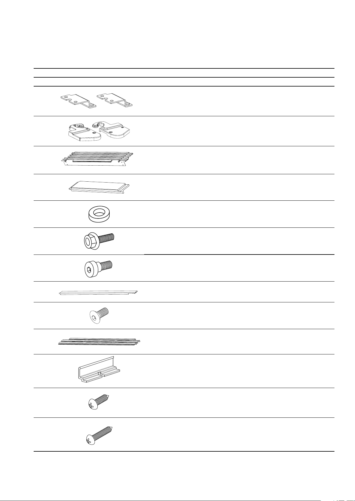
TRIM KIT CONTENTS
(SINGLE & DUAL REFRIGERATOR INSTALLATION)
FOR STEP 1 - INSTALLING THE LEVELLING SYSTEM (PAGE 9)
Item description ANC quantity
1
Replacement
foot base with
M4 threaded
holes
A02102702 2 2
ETK7000/8000
ETK7080/7070
/8080
2
3
5
6
7
Replacement
hinge base
LH/RH
Leveller
assembly
Space leveller
8.4mm
Screw trilobular
M5 x 26mm
Screw self
tapping 6 x
30mm
A0181990 8
A01819907
297276901 2 4
A06128901 6 12
811949405 8 16
808199002 2 4
1
1
1
1
8
9
Leg leveller 21639690 0 2 4
Clip trim bottom A0 6 6 74 5 01 2 4
NOTE:
Kits contain additional parts for installation of various models.
Page 5
TRIM KIT CONTENTS
(SINGLE REFRIGERATORS)
Item description ANC quantity
ETK7000 ETK8000
1
Bracket top trim LH
& RH
A06147601
A0614760 2
1
1
5
1
1
2
3
4
5
(2H)
6
(8H)
7
(6H)
8
9
Top hinge cover LH
& RH
Top trim 7000
Top trim 8000
Insert top trim A06147901 1 1
Spacer 3mm top trim
bracket
Screw trilobular
M5 x 10mm
Shoulder bolt
M5 x 10mm
(No. 4 allen key)
Side trim
LH & RH
Screw counter sunk M4A0 6 351501 2 2
A06219901
A0 6219801
A06127901
A06127902
A06351301 2 2
811949402 4 4
A06350601 2 2
A0 6128802
A06128801
1
1
1
1
1
1
1
1
1
1
(5H)
10
11
12
(10H)
13
(4H)
Bottom trim 7000
Bottom trim 8000
Insert bottom trim A06336001 1 2
Screw 6G x 1/4” type
AB pan head phillips
Screw 8G x 1/2” type
AB pan head phillips
A0 615370
A0 615370
A06809601 1 2
1449 422 4 4
NOTE:
Kits contain additional parts for installation of various models.
1
1
Page 6
6 electrolux.com.au
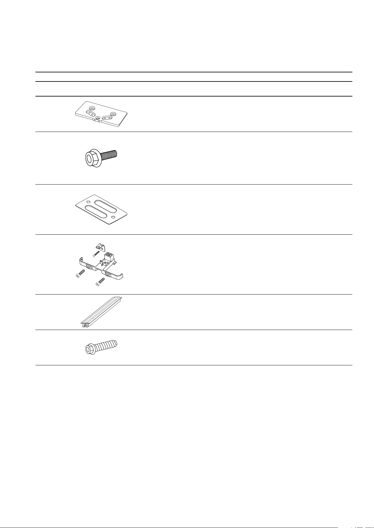
TRIM KIT CONTENTS
(DUAL REFRIGERATORS INSTALLATION ONLY)
FOR STEP 2 - JOINING THE REFRIGERATORS (PAGE 10)
Item description ANC quantity
1
Top front bracket A03972801 1
ETK7080/7070
/8080
2
(8H)
3
4
5
Screw trilobular
M5 x 13mm
Bottom rear bracket A03979601 1
Bottom front bracket
assembly
M4 screws x 2
Centre trim assembly A03973701 1
811949402 6
A03973402 1
6
Screw thread cutting
#8 x 5/8
1460 5 83 1
NOTE:
Kits contain additional parts for installation of various models.
Page 7

TRIM KIT CONTENTS
(DUAL REFRIGERATORS INSTALLATION)
Item description ANC quantity
ETK7080 ETK7070 ETK8080
1
Bracket top trim LH
& RH
A06147601
A0614760 2
1
1
1
1
7
1
1
2
3
4
(8H)
5
(6H)
6
Top hinge cover LH
& RH
Top trim - 7080
Top trim - 7070
Top trim - 8080
Screw trilobular
M5 x 13mm
Shoulder bolt
M5 x 10mm
(No.4 allen key)
Side trim
LH & RH
A06219901
A0 6219801
A06127905
A06127903
A06127904
811949402 4 4 4
A06350601 2 2 2
A0 6128802
A06128801
1
1
1
1
1
1
1
1
1
1
1
1
1
1
1
7
(85H)
8
9
(4H)
Screw counter sunk M4A0 6 351501 2 2 2
Bottom trim - 7080
Bottom trim - 7070
Bottom trim - 8080
Screw 8G x 1/2” type
AB pan head phillips
A0 6153705
A0 6153703
A0 6153704
1449 422 4 4 4
1
1
1
NOTE:
Kits contain additional parts for installation of various models.
Page 8

8 electrolux.com.au
WARNING
Safety: Always wear safety glasses when using power tools.
Tools needed:
TM
Phillips
Screwdriver, Tape Measure, Socket Wrench 8mm,
Flat Tip Screwdriver, Power Drill, Dia 3.2mm drill bit, Step Ladder,
4mm Allen key
TRIM KIT OVERALL OUTER
DIMENSIONS (ASSEMBLED)
KIT NO. WIDTH (W) HEIGHT (H)
ETK7000 836 mm 1904 mm
ETK8000 936 mm 1904 mm
ETK7070 1551 mm 1904 mm
ETK7080 1651 m m 1904 mm
ETK8080 174 6 m m 1904 mm
SINGLE INSTALLATION:
W
DUAL INSTALLATION:
H
W
H
IMPORTANT
When joining a 700 mm and 800 mm refrigerator,
the 700 mm must be placed on the left.
Page 9

CABINETRY DIMENSIONS:
(INSTALLATION)
Recommended minimum rear gaps for
adequate ventilation:
min
50 mm
9
min
100 mm
min
50 mm
PROUD INSTALLATION
KIT NO. WIDTH (W1)* DEPTH (D1) HEIGHT (H1)
ETK7000 800 mm 680 mm
ETK8000 900 mm 680 mm (min) 1807 mm
ETK7070 1515 mm 680 mm (min) 1807 m m
ETK7080 1615 mm 680 mm (min) 18 07 mm
ETK8080 1710 m m 680 mm (min) 1807 mm
*Dimension allows 5mm clearance / side
(min) 1807 m m
H1 ± 2mm
D1
(min)
W1
Page 10

10 electrolux.com.au
STEP 1 - INSTALLING THE
LEVELLING SYSTEM
FOR SINGLE AND DUAL
REFRIGERATOR IN STALL ATIONS
Leveling system install
Preparing non-door hinge side
a. Tape door(s) to cabinet (to maintain door alignment)
and lay refrigerator(s) on its back on packaging
material or a drop cloth to prevent damage.
b. Remove large levelling nut by turning anti clockwise
past the stop (discard)
c. Remove the two outside screws (1&2) and roller
assembly (discard). Remove the two inside screws
(3&4) (keep) and discard the foot base
4
1
3
2
Attaching the levelling systems (2 per refrigerator)
a. The leveller assembly attaches to the refrigerator with
3 spacers (1H) and 3 screws 9H and 3H (Fig 5).
b. Ensuring slotted adjusting bolt is at the front, align
the side of the leveller assembly to the side of the
refrigerator.
2 x 9h
1 x 3h
3 x 1h
Figure 5
(recommended
torque 8Nm)
c. Attach Leg leveller to the leveller hole farthest from
the cabinet side face and wind it up fully. (Fig 6)
5
Figure 2
d. Remove screw (5) on the compressor base
e. Attach replacement foot base to the refrigerator to
the two holes at the front of the refrigerator using
two of the removed screws (See Figure 3)
Ensure tapped
hole is on the
outside of
refrigerator
(recommended
torque 8Nm)
Figure 3
(recommended
torque 8Nm)
f. Discard the factory fitted base and remaining screws.
g. For french door models, repeat the steps ‘b’ to ‘d’ on
other side of the refrigerator
Preparing door hinge side (non french door models)
a. Remove large levelling nut by turning anti-clockwise
past the stop (discard). Remove the two outside
screws and roller assembly (discard). remove the two
inside screws (keep) and discard hinge assembly.
b. Ensuring the doors are properly aligned, attach the
Hinge Base included in the Trim Kit using removed
screws 3 and 4 (Fig 4). For Right Hand models, use
‘Hinge Base Right Assy’ and for Left Hand models,
use ‘Hinge Base Left Assy’
Figure 6
d. Attach Clip Trim Bottom to the inside of each leveller
assembly using screws 9H
9H
Figure 7
e. Repeat the procedure to fix the other levelling system
to other side of the refrigerator.
Stand the appliance(s) to vertical position.
Your refrigerators are delivered with hole covers that cover
the screw holes. These holes are located on the top of the
refrigerator, opposite from the door hinge. Carefully remove
these covers, care must be taken to avoid damaging the
refrigerators surface. Use the pry slot at the rear of the cover.
remove covers
Figure 4
Figure 8
Page 11

STEP 2 - JOINING THE REFRIGERATORS
FOR DUAL REFRIGERATOR INSTALLATION
ON LY
11
Carefully pull the refrigerators together adjacent to the final
installation location, then adjust the front and rear feet to
the same height.
Top-front and bottom-rear bracket installation
Install the top-front bracket
• Assemble the top-front bracket, fit the screws (8H) in
place, but do not tighten them yet leave the screws
loose.
do not tighten
Figure 9
Install the bottom rear bracket
Bottom-front bracket installation
Position the bottom-front bracket
• Position the bottom-front bracket between the
two refrigerators.
• Fasten with the two M4 screws using a Phillips
head screwdriver.
• Pull tensioner towards front to allow fitment of
centre trim
extract the
tensioner
Fig ure 11
Fit the centre cover
• Remove 2 screws at the bottom of rear panel
• Assemble the rear-bottom rear bracket to the
refrigerators using the original screws and tighten.
• Push the centre trim between the two refrigerators
• Engage the bottom end of the centre trim into the
tensioner of the bottom-front bracket. (Fig. 12)
• Lift the top-front bracket (screws should be loose
enough) and slide the centre trim underneath.
(F ig. 13)
• Tighten the screws in the top-front bracket. (Fig. 14)
• Adjust the tensioner screw as required. (Fig. 15)
• Fasten the centre trim to the top-front bracket using
the provided self-tapping screw. (Fig. 16)
fit bottom first
Figure 12
Figure 10
Page 12

12 electrolux.com.au
lift top front bracket
slide centre
trim under
Fig ure 13
tighten all
screws
tensioner screw
Figure 14
Fig ure 15
self tapping
screw
Figure 16
Page 13

STEP 3 - INSTALLING THE TRIMS
AND LEVELLING
FOR SINGLE & DUAL REFRIGERATOR
INSTALLATIONS
Trim kit installation
Single unit installation – non french door models
Attaching the bracket – non hinge side
a. Attach the bracket to the unit using two screws.
2X8H
13
Figure 20
IMPORTANT
Door alignment
Fi gure 17
Single and dual installations
Attaching the bracket – hinge side
a. Remove outer screw from top hinge cover and save
for later. Remove the top hinge cover and discard.
(F ig. 18)
Figure 18
b. Remove the two screws shown. Attach the bracket
to the top hinge using the removed screws.
Recommended screw torque 8Nm.
a. Push refrigerator(s) into final position to check
alignments.
b. Align refrigerator cabinet(s) using the leveller assembly
using the adjuster bolt to raise or lower the rear roller
c. Raise front using leg leveller (N.B. you will need to
wind back up to move refrigerators forward)
d. Align top doors by loosening top hinge - tighten
screws.
e. Pull refrigerator(s) forward to complete final steps
French and Dual door Installations
a. (French Door model Only) Attach the bracket LH and
Replacement Top Hinge Cover on the other door
hinge as well.
b. (Dual Installation Only) Attach the bracket and
Replacement Top Hinge Cover on door hinge side of
second are refrigerator as well.
Top Trim Install
Single installation only Non-French door models
Figure 19
c. Assemble the Replacement Top Hinge Cover to the
Top Hinge using the screw removed from factory
fitted Top Hinge Cover. (Fig. 20)
Attach Insert Top Trim to top trim by pushing into the slot
on the non-hinge side of the refrigerator.
Figure 21
Page 14

14 electrolux.com.au
All models
Align the front of the top trim to the front of the refrigerator
and attach with screws (8H) and spacer 2H (Non French
Door models only) as shown. (Fig. 22)
Single
2x8H
Spacer(2H)
not required
for french door
Dual
2x8H
2x8H
2x2H
2x8H
Figure 22
c. Locate side trim over the top trim and attached with
countersunk self tapping screws (5H) (Fig. 25). Push
side trim again against refrigerator to close gap
before tightening.
5H
Figure 25
d. Assemble the left hand side trim to the appliance
using the same method.
Push the appliance(s) carefully into the cabinetry
cavity until the trims are close to the cabinetry front
faces. (Fig. 26)
Side trim install
a. Attach a shoulder screw into the lower side hole on
outward facing side of levelling systems (Fig. 23).
For dual installation, do this only on the extreme left
and extreme right levelling systems.
Figure 23
6H
b. Locate slot in right hand side trim over shoulder
sc rew.
Figure 24
Page 15

Figure 26
e. Adjust the front and rear levelling feet (Fig. 27) if
necessary to align the edges of the trims to the
front face of the cabinetry.
15
h. Drill dia 3.2mm pilot holes on the cabinetry and
secure the Top Trim to the cabinetry using two
screws each on left and right ends.
2x4H
Figure 30
i. Attach both the side trims back to the unit
Figure 27
To r ais e
back of the
unit, adjust
bolt clockwise
To raise front
of the unit,
adjust the
front feet
f. Adjust the leg levellers (Fig. 28) so that they touch the
ground and can’t be rotated further by bare hands.
This will stop the refrigerator rolling forward when
opening the doors.
Figure 28
Bottom trim install
Single installation only
Attach the insert bottom trim to the slot on the
non-hinge side using screw 10H.
10H
Figure 31
Single and dual Installations
Open doors and align the bottom trim between the clips
and push to clip it in place.
g. Remove the screws holding the side trim to the top
trim and take out the side trim by carefully sliding it
up and away from the unit.
Figure 29
Figure 32
Page 16

16 electrolux.com.au
Uninstall Sequence
1. Uninstalling the trims
a. Remove the bottom trim by pulling it towards you.
b. Remove the Side trims by pulling it up and away from
the refrigerator after unscrewing the top screw.
c. Remove the screws attaching the top trim to timber
cabinetry.
d. Pull out the refrigerator from the cabinetry cavity.
e. Remove the top trim.
2. Uninstall the Connection kit components
a. Remove the top front bracket.
b. Loosen the tensioner screw on the bottom bracket
and remove the centre cover.
c. Remove the bottom front bracket.
d. Remove the rear bottom bracket.
3. Remove the Levellers
4. Attach Roller Feet
Page 17

NOTES
17
Page 18

18 electrolux.com.au
NOTES
Page 19

Warranty
FOR SALES IN AUSTRALIA AND NEW ZEALAND
APPLIANCE: ELECTROLUX SPARE PARTS & ACCESSORY PRODUCTS
This document sets out the terms and conditions of the product
warranties for Electrolux Spare Parts and Accessory Products. It is
an important document. Please keep it with your proof of purchase
documents in a safe place for future reference should there be a
manufacturing defect in your Product. This warranty is in addition to
other rights you may have under the Australian Consumer Law.
1. In this warranty:
(a) ‘ACL’ or ‘Australian Consumer Law’ means Schedule 2 to the
Competition and Consumer Act 2010;
(b) ‘Product’ means any Electrolux spare part and accessory product
purchased by you and accompanied by this document;
(c) ‘ASPD’ means Electrolux’s Authorised Spare Parts Distributor;
(d) ‘Electrolux’ is the brand controlled by Electrolux Home Products Pty
Ltd of 163 O’Riordan Street, Mascot NSW 2020, ABN 51 004 762
341 in respect of Products purchased in Australia and Electrolux (NZ)
Limited (collectively “Electrolux”) of 3-5 Niall Burgess Road, Mount
Wellington, in respect of Products purchased in New Zealand;
(e) ‘WarrantyPeriod’meanstheperiodspeciedinclause3ofthis
warranty;
(f) ‘you’ means the purchaser of the Product not having purchased the
Product for re-sale, and ‘your’ has a corresponding meaning.
2. Application: This warranty only applies to new Products, purchased
and used in Australia or New Zealand and is in addition to (and does
not exclude, restrict, or modify in any way) other rights and remedies
under a law to which the Products or services relate, including any nonexcludable statutory guarantees in Australia and New Zealand.
3. Warranty Period: Subject to these terms and conditions, this warranty
continues for a period of 12 months in Australia and New Zealand,
following the date of original purchase of the Product.
4. Repair or replace warranty: During the Warranty Period, Electrolux or
its ASPD will, at no extra charge, subject to these terms and conditions,
repair or replace any Product or parts which it considers to be defective.
Electrolux may, in its absolute discretion, choose whether the remedy
oeredforavalidwarrantyclaimisrepairorreplacement.Electroluxorits
ASPD may use refurbished parts to repair your Product. You agree that
any replaced Products or parts become the property of Electrolux.
5. Travel and transportation costs: Subject to clause 7, Electrolux will
bear the reasonable cost of transportation, travel and delivery of the
Product to and from Electrolux or its ASPD. Travel and transportation
will be arranged by Electrolux as part of any valid warranty claim.
6. Proof of purchase is required before you can make a claim under this
warranty.
7. Exclusions: You may not make a claim under this warranty unless
the defect claimed is due to faulty or defective parts or workmanship.
This warranty does not cover:
(a) lightglobes,batteries,ltersorsimilarperishableparts;
(b) parts and Products not supplied by Electrolux;
(c) cosmeticdamagewhichdoesnotaecttheoperationofthe
Product;
(d) damage to the Product caused by:
(i) negligence or accident;
19
(ii) misuse or abuse, including failure to properly maintain or service;
(iii) improper, negligent or faulty servicing or repair works done by
anyone other than an Electrolux authorised repairer or ASPD;
(iv) normal wear and tear;
(v) power surges, electrical storm damage or incorrect power supply;
(vi) incomplete or improper installation;
(vii) incorrect, improper or inappropriate operation;
(viii) insect or vermin infestation;
(ix) failure to comply with any additional instructions supplied with
the Product;
In addition, Electrolux is not liable under this warranty if:
(a) the Product has been, or Electrolux reasonably believes that the
Product has been, used for purposes other than those for which the
Product was intended, including where the Product has been used
for any non-domestic purpose;
(b) theProductismodiedwithoutauthorityfromElectroluxinwriting;
(c) the Product’s serial number or warranty seal has been removed
or defaced.
8. How to claim under this warranty: To enquire about claiming under
this warranty, please follow these steps:
(a) carefully check the operating instructions, user manual and the
terms of this warranty;
(b) have the model and serial number of the Product available;
(c) have the proof of purchase (e.g. an invoice) available;
(d) telephone the numbers shown below.
9. Australia: For Products and services provided by Electrolux in Australia:
Electrolux goods come with guarantees that cannot be excluded under
the Australian Consumer Law. You are entitled to a replacement or
refund for a major failure and for compensation for any other reasonably
foreseeable loss or damage. You are also entitled to have the Product
repaired or replaced if the Product fails to be of acceptable quality and
the failure does not amount to a major failure. ‘Acceptable quality’ and
‘major failure’ have the same meaning as referred to in the ACL.
10. New Zealand: For Products and services provided by Electrolux in New
Zealand, the Products come with a guarantee by Electrolux pursuant
to the provisions of the Consumer Guarantees Act, the Sale of Goods
Act and the Fair Trading Act. Where the Product was purchased in New
Zealand for commercial purposes the Consumer Guarantee Act does
not apply.
11.Condentiality: You accept that if you make a warranty claim, Electrolux
and its agents including ASPD may exchange information in relation to
you to enable Electrolux to meet its obligations under this warranty.
Before calling for service, please ensure that the steps listed in clause 8 above have been followed.
FOR SERVICE
ortondtheaddressofyournearest
customer care centre in Australia
PLEASE CALL 1300 363 640
For the cost of a local call (Australia only)
FOR SERVICE
ortondtheaddressofyournearest
authorised service centre in New Zealand
PLEASE CALL 0800 10 66 10
(New Zealand only)
ESP&A_Warr_May17
Important Notice
AUSTRALIA
ELECTROLUX HOME PRODUCTS
163 O’Riordan Street, Mascot NSW 2020
electrolux.com.au
NEW ZEALAND
ELECTROLUX (NZ) Limited
3-5 Niall Burgess Road, Mount Wellington
electrolux.co.nz
FOR SPARE PARTS
ortondtheaddressofyournearest
spare parts distributor in Australia
PLEASE 13 13 50
For the cost of a local call (Australia only)
FOR SPARE PARTS
ortondtheaddressofyournearest
spare parts centre in New Zealand
PLEASE 0800 10 66 20
(New Zealand only)
Page 20

Electrolux Home Products Australia
telephone: 1300 363 640
fax: 1800 350 067
email: customercare@electrolux.com.au
web: electrolux.com.au
Electrolux Home Products New Zealand
telephone: 0800 234 234
fax: 0800 363 600
email: customercare@electrolux.co.nz
web: electrolux.co.nz
P/No. A06440801
© 2017 Electrolux Home Products Pty Ltd
EMAN_TrimKit_Nov17
 Loading...