

Electrolux EILFU17GS, EILFU21GS Technical & Service Manual
FREEZER SERVICE MANUAL #5995516548 2008 ALL RIGHTS RESERVED
UUpprriigghhtt FFrreeeezzeerr
EEIILLFFUU1177GGSS && EEIILLFFUU2211GGSS
TTeecchhnniiccaall SSeerrvviiccee MMaannuuaall


1-1
SSeeccttiioonn 11
BBaassiicc IInnffoorrmmaattiioonn
BBaassiicc IInnffoorrmmaattiioonn

BBaassiicc IInnffoorrmmaattiioonn
1-2
SSeeccttiioonn 11 -- BBaassiicc IInnffoorrmmaattiioonn
................................
11--11
Table of Contents.................................................... 1-2
Safe Servicing Practices ........................................ 1-3
Features .................................................................. 1-4
Serial Number Breakdown...................................... 1-4
EILFU17GS0 .......................................................... 1-5
EILFU21GS0 .......................................................... 1-6
SSeeccttiioonn 22 -- IInnssttaallllaattiioonn IInnffoorrmmaattiioonn
................................................ 22--11
Important Safety Instructions ................................ 2-2
Safety Precautions.................................................. 2-2
Location .................................................................. 2-4
Electrical Information .............................................. 2-5
Leveling .................................................................. 2-6
Door Removal ........................................................ 2-6
Water Supply .......................................................... 2-7
Unit Dimensions...................................................... 2-8
SSeeccttiioonn 33 -- EElleeccttrroonniicc CCoonnttrrooll ................................................................ 33--11
Electronic Temperature Control.............................. 3-2
Setting Freezer Control .......................................... 3-2
Alarm Function Table .............................................. 3-2
Normal Operation .................................................. 3-3
Temperature Display ............................................ 3-3
Temperature Scale................................................ 3-3
Fast Freeze .......................................................... 3-3
Control Lock ........................................................ 3-3
Mute Sounds ........................................................ 3-3
Alarms .................................................................... 3-4
Temperature Alarm .............................................. 3-4
Power Fail Alarm .................................................. 3-4
Door Ajar .............................................................. 3-4
Communication Error .......................................... 3-4
Thermistor Error.................................................... 3-4
Stuck Key Error .................................................... 3-4
Fail Safe Mode...................................................... 3-4
Defrost Mode .......................................................... 3-5
Defrost Timing ........................................................ 3-5
Manual Defrost ...................................................... 3-5
Showroom Mode .................................................... 3-5
Test Mode .............................................................. 3-5
Service Diagnostic Mode........................................ 3-6
Initiate Service Mode............................................ 3-6
Model Identification .............................................. 3-6
Software Version .................................................. 3-6
Door Switch Status .............................................. 3-6
Thermistor Status ................................................ 3-6
Reset Factory Defaults ........................................ 3-6
Exit Diagnostics Mode.......................................... 3-6
SSeeccttiioonn 44-- RReeffrriiggeerraattiioonn SSyysstteemm
........................................................ 44--11
Definitions .............................................................. 4-2
Safety Warnings...................................................... 4-2
Charging Sealed Systems ...................................... 4-2
Soldering ................................................................ 4-3
Basic Components ................................................ 4-3
Perimeter Hot Tube ................................................ 4-3
Refrigerant Cycle .................................................... 4-3
Low/High Side Leak or Undercharge .................... 4-4
Testing for Refrigerant Leaks.................................. 4-4
Compressor Replacement...................................... 4-4
To Flush the System .............................................. 4-5
To Use Dry Nitrogen to Flush the System .............. 4-5
To Use Refrigerant to Flush the System ................ 4-5
Installing a New Compressor ................................ 4-6
Condenser Replacement ........................................ 4-7
Filter-Drier Replacement ........................................ 4-8
Evaporator and Suction Line Replacement............ 4-8
Equipment Needed for Evacuation & Recharging.. 4-9
Installing Evacuation and Recharging Equipment.. 4-9
Evacuating System ................................................ 4-10
Charging the System .............................................. 4-10
Preparing the Charging Cylinder ............................ 4-10
Final Leak Test ........................................................ 4-11
Verify Refrigerant Type in the System .................... 4-12
Dedicated Equipment ............................................ 4-12
R-134a Refrigeration Systems................................ 4-12
Miscibility of R-134a and Ester Oil ........................ 4-12
Water in the Refrigeration System.......................... 4-13
Vacuum Pump Maintenance .................................. 4-14
Refrigerant Leaks.................................................... 4-14
Leak Detection........................................................ 4-15
R-134a Properties .................................................. 4-15
HFC-134a, CFC-12 Pressure Temp. Chart ............ 4-16
Inhalation Toxicity .................................................. 4-17
Cardiac Sensitization .............................................. 4-17
Spills or Leaks ........................................................ 4-17
Skin and Eye Contact ............................................ 4-17
Combustibility of HFC-134a .................................. 4-18
Leak Testing............................................................ 4-18
Bulk Delivery and Storage ...................................... 4-18
Filling and Charging Operations ............................ 4-18
Refrigerant Recovery Systems .............................. 4-18
Thermal Decomposition.......................................... 4-18
SSeeccttiioonn 55-- CCoommppoonneenntt TTeeaarrddoowwnn
.................................................... 55--11
Warnings and Cautions .......................................... 5-2
Exterior Components.............................................. 5-3
Door Handle ........................................................ 5-3
Kickplate .............................................................. 5-3
Door Hinge and Door Assembly .......................... 5-3
Lower Hinge Assembly ........................................ 5-4
Door Gasket and Inner Panel .............................. 5-4
Door Lock ............................................................ 5-5
Control Panel........................................................ 5-5
Tilt-Out Wire Shelf ................................................ 5-5
Door Shelf Guard.................................................. 5-6
Door Switch .......................................................... 5-6
Interior Components .............................................. 5-6
Upper Shelf Assembly.......................................... 5-6
Wire Basket .......................................................... 5-7
Wire Basket Slide ................................................ 5-7
Light Shield .......................................................... 5-7
Light Fixture.......................................................... 5-7

1-3
SSaaffee SSeerrvviicciinngg PPrraaccttiicceess
AAvvooiidd ppeerrssoonnaall iinnjjuurryy aanndd//oorr pprrooppeerrttyy ddaammaaggee bbyy
oobbsseerrvviinngg iimmppoorrttaanntt SSaaffee SSeerrvviicciinngg PPrraaccttiicceess..
FFoollllo
owwiinngg aarree ssoommee lliimmiitteedd eexxaammpplleess ooff ssaaffee
pprraaccttiicceess::
1. DO NOT attempt a product repair if you have
any doubts as to your ability to complete the
repair in a safe and satisfactory manner.
2. Always Use The Correct Replacement Parts as
indicated in the parts documentation.
Substitutions may defeat compliance with
Safety Standards Set For Home Appliances.
Do not exceed maximum recommended
wattage on light bulb replacements. Doing so
could blow fuses and/or damage transformers.
3. Before servicing or moving an appliance:
• Remove power cord from the electrical outlet,
trip circuit breaker to the OFF position, or
remove fuse.
• Turn off water supply.
4. Never interfere with the proper operation of any
safety device.
5. Use ONLY REPLACEMENT PARTS
CATALOGED FOR THIS APPLIANCE.
Substitutions may defeat compliance with
Safety Standards Set For Home Appliances.
6. GROUNDING: The standard color coding for
safety ground wires is GREEN, or GREEN with
YELLOW STRIPES. Ground leads are not to be
used as current carrying conductors. It is
EXTREMELY important that the service
technician reestablish all safety grounds prior
to completion of service. Failure to do so will
create a hazard.
7. Prior to returning the product to service, ensure
that:
• All electrical connections are correct and
secure.
• All electrical leads are properly dressed and
secured away from sharp edges, hightemperature components, and moving parts.
• All non-insulated electrical terminals,
connectors, heaters, etc. are adequately
spaced away from all metal parts and panels.
• All safety grounds (both internal and external)
are correctly and securely connected.
• All panels are properly and securely
reassembled
Baffle Plate .......................................................... 5-8
Icemaker .............................................................. 5-8
Evaporator Cover ................................................ 5-8
Evaporator Fan Assembly .................................... 5-9
Defrost Thermostat .............................................. 5-9
Thermistor ............................................................ 5-9
Defrost Heater ...................................................... 5-10
Evaporator .......................................................... 5-10
Compressor Area.................................................... 5-11
Power Cord ............................................................ 5-11
Water Valve ............................................................ 5-11
Filter-Drier .............................................................. 5-12
Compressor ............................................................ 5-13
Drain Pan ................................................................ 5-14
Condenser Fan Motor ............................................ 5-14
Condenser .............................................................. 5-15
Control Module ...................................................... 5-15
SSeeccttiioonn 66-- IIcceemmaakkeerr
............................................................................................ 66--11
Rear Mounted Icemaker ........................................ 6-2
Icemaker Components .......................................... 6-3
Front Cover ............................................................ 6-3
Ice Mold .................................................................. 6-3
Mold Heater ............................................................ 6-3
Ice Stripper ............................................................ 6-3
Water Valve Assembly ............................................ 6-3
Thermostat.............................................................. 6-3
Sensing Arm and Linkage ...................................... 6-3
Timing Switches .................................................... 6-4
Thermal Cut-Out (TCO) .......................................... 6-4
Timing Cam and Coupler........................................ 6-4
Timing Gear ............................................................ 6-4
Motor ...................................................................... 6-4
On/Off Switch ........................................................ 6-4
Wiring...................................................................... 6-4
Installing Water Supply Line to Icemaker .............. 6-5
Water Valve Switch- Water Fill Volume .................. 6-5
Test Cycling Icemaker ............................................ 6-5
Operating Cycle Illustrations-Manual Cycle .......... 6-6
Operating Cycle Illustrations-Electrical .................. 6-6
Operating Cycle Illustrations-Mechanical .............. 6-13
Ice Maker Electrical Diagram.................................. 6-16
SSeeccttiioonn 77-- PPaarrttss LLiisstt aanndd EExxppllooddeedd VViieewwss
........................ 77--11
Door Components EILFU17GS .............................. 7-2
Cabinet Components EILFU17GS.......................... 7-4
System Components EILFU17GS .......................... 7-6
Door Components EILFU21GS .............................. 7-8
Cabinet Components EILFU21GS.......................... 7-10
System Components EILFU21GS .......................... 7-12
Ice Maker Components ........................................ 7-14
SSeeccttiioonn 88-- TTrroouubblleesshhoooottiinngg
........................................................................ 88--11
Troubleshooting Chart ............................................ 8-2
SSeeccttiioonn 99-- WWiirriinngg DDiiaaggrraammss........................................................................ 99--11
Wiring Diagram ...................................................... 9-2
BBaassiicc IInnffoorrmmaattiioonn
2211 CCuu.. FFtt.. UUpprriigghhtt FFrreeeezzeerr
EEIILLFFUU2211GG SS
Ye s
20.6 Cu. Ft.
23.2 Sq. Ft.
Ye s
Ye s
Ye s
Ye s
Ye s
Ye s
Ye s
Ye s
Ye s
Ye s
2
2
3
2
1
3
Ye s
Ye s
Ye s
Right Bottom Rear
Left Bottom Rear
115V/60Hz/15A
.69
15
251 Lbs
269 Lbs
FFeeaattuurreess
Energy Star
Total Volume
Shelf Area
IQ Touch Electronic Control
Digital Exterior Control Center
Frost-Free Performance
Adjustable Temperature Control
Display Temperature Mode
Fast Freeze
High Temperature Alarm System
System Error Alarm
Interior Lighting
Power On Light
Adjustable Glass Shelves
Fixed Glass Shelves
Full Access Baskets
Adjustable Door Bins
Contour Door Shelves
Tilt Out Wire Door Shelves
Automatic Icemaker
Lock With Pop Out Key
Automatic Door Closer
Specifications
Power Supply Connection
Water Inlet Location
Voltage Rating
Connected Load @ 115V
Minimum Circuit Required Amps
Product Weight
Shipping Weight (Approx.)
1177 CCuu.. FFtt.. UUpprriigghhtt FFrreeeezzeerr
EEIILLFFUU1177GG SS
Ye s
16.8 Cu. Ft.
20 Sq. Ft.
Ye s
Ye s
Ye s
Ye s
Ye s
Ye s
Ye s
Ye s
Ye s
Ye s
2
2
2
2
1
2
Ye s
Ye s
Ye s
Right Bottom Rear
Left Bottom Rear
115V/60Hz/15A
.62
15
225 Lbs
240 Lbs
BBaassiicc IInnffoorrmmaattiioonn
1-4
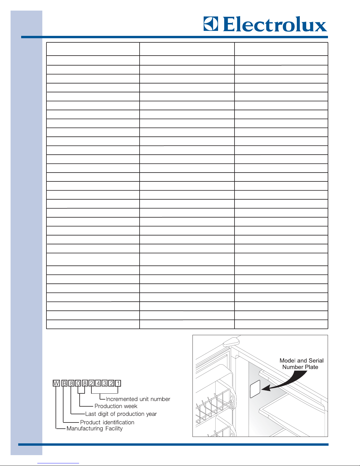
SSeerriiaall NNuummbbeerr BBrreeaakkddoowwnn
The serial plate is located on the left side wall of
the freezer interior.
BBaassiicc IInnffoorrmmaattiioonn
1-5
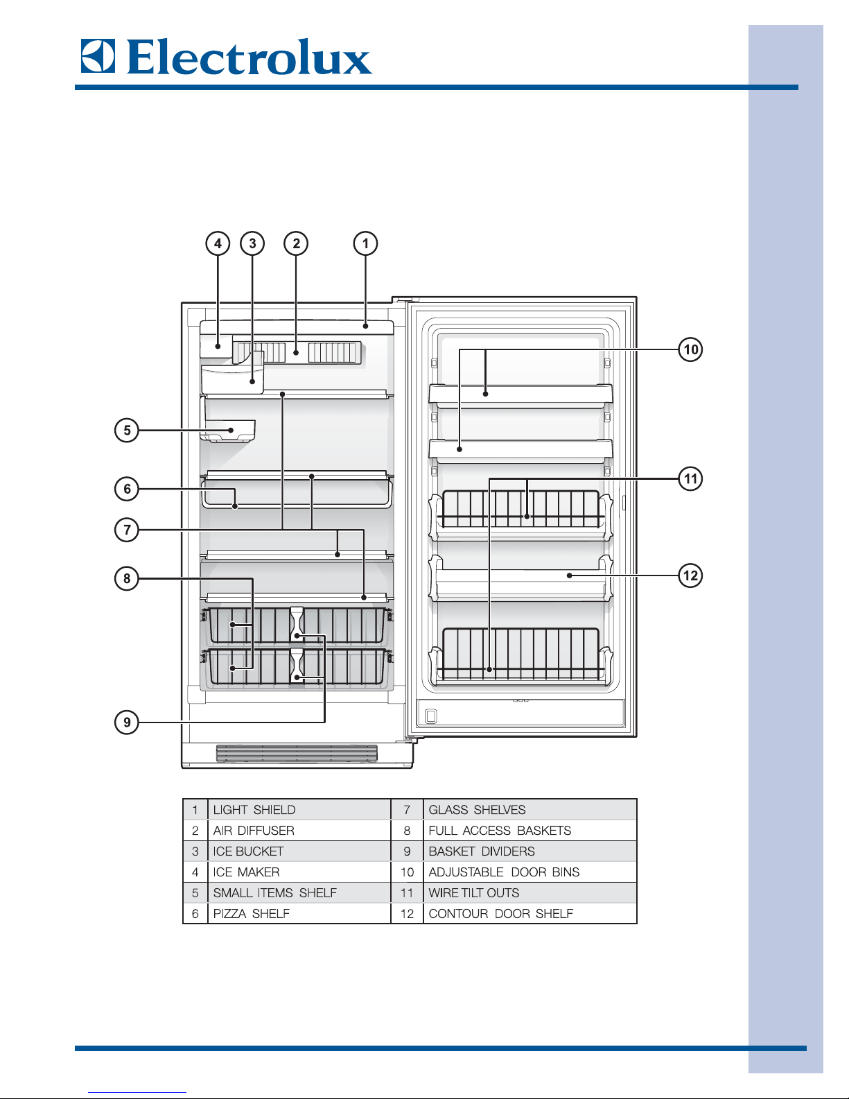
UUnnddeerrssttaannddiinngg FFeeaattuurreess AAnndd TTeerrmmss
Electrolux freezers are designed for optimal convenience and storage flexibility. Use the illustration below
to familiarize yourself with product features and terminology.
NNOOTTEE::
Features may vary according to model.
1177 CCUU.. FFTT.. MMOODDEELL SSHHOOWWNN
BBaassiicc IInnffoorrmmaattiioonn
1-6
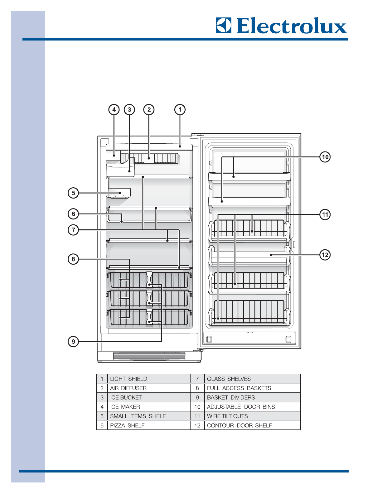
UUnnddeerrssttaannddiinngg FFeeaattuurreess AAnndd TTeerrmmss
Electrolux freezers are designed for optimal convenience and storage flexibility. Use the illustration below
to familiarize yourself with product features and terminology.
NNOOTTEE::
Features may vary according to model.
2211 CCUU.. FFTT.. MMOODDEELL SSHHOOWWNN

IInnssttaallllaattiioonn IInnffoorrmmaattiioonn
2-1
SSeeccttiioonn 22
IInnssttaallllaattiioonn IInnffoorrmmaattiioonn

IInnssttaallllaattiioonn IInnffoorrmmaattiioonn
2-2
IIMMPPOORRTTAANNTT SSAAFFEETTYY IINNSSTTRRUUCCTTIIOONNSS
SSaaffeettyy PPrreeccaauuttiioonnss
Do not attempt to install or operate this appliance until you read the safety precautions in this guide.
Safety items throughout this guide are labeled with a Warning or Caution based on the risk type.
WWAARRNNIINNGG
indicates a potentially hazardous situation which, if not avoided, could result in death or
serious injury.
CCaauuttiioonn
indicates a potentially hazardous situation which, if not avoided, may result in minor or
moderate injury.
WARNING
EELLEECCTTRROOLLUUXX CCAANNNNOOTT BBEE HHEELLDD RREESSPPOONNSSIIBBLLEE FFOORR DDAAMMAAGGEE TTOO PPRROOPPEERRTTYY OORR IINNJJUURRYY TTOO
PPEERRSSOONNSS CCAAUUSSEEDD BBYY FFAAIILLUURRE
E TTOO CCOOMMPPLLYY WWIITTHH TTHHEE IINNSSTTAALLLLAATTIIOONN,, MMAAIINNTTEENNAANNCCEE AANNDD
SSAAFFEETTYY IINNSSTTRRUUCCTTIIOONNSS CCOONNTTAAIINNEEDD IINN TTHHIISS SSEERRVVIICCEE MMAANNUUAALL..
WARNING
TTOO RREEDDUUCCEE TTHHEE RRIISSKK OOFF FFIIRREE,, EELLEECCTTRRIICCAALL SSHHOOCCKK,, OORR IINNJJUURRYY WWHHEENN UUSSIINNGG YYOOUURR FFRREEEEZZEERR,,
FFOOLLLLOOWW BBAASSIICC SSAAFFEETTYY PPRREECCAAUUTTIIOONNSS IINNCCLLUUDDIINNGG TTHHEE FFOOLLLLOOWWIINNGG::
-- RREEAADD AALLLL IINNSSTTRRUUCCTTIIOONNSS BBEEFFOORREE OOPPEERRAATTIINNGG TTHHEE FFRREEEEZZEERR..
-- BBEEFFOORRE
E PPEERRFFOORRMMIINNGG AANNYY TTYYPPEE OOFF SSEERRVVIICCEE OORR IINNSSTTAALLLLAATTIIOONN,, MMAAKKEE SSUURREE TTHHAATT
EELLEECCTTRRIICC PPOOWWEERR TTOO TTHHEE FFRREEEEZZEERR IISS DDIISSCCOONNNNEECCTTEEDD..
-- TTOO AAVVOOIIDD TTHHEE PPOOSSSSIIBBIILLIITTYY OOFF EEXXPPLLOOSSIIOONN OORR FFIIRREE,, DDOO NNOOTT SSTTOORREE OORR UUSSEE CCOOMMBBUUSSTTIIBBLLEE,,
FFLLAAMMMMAAB
BLLEE,, OORR EEXXPPLLOOSSIIVVEE LLIIQQUUIIDDSS OORR VVAAPPOORRSS ((SSUUCCHH AASS GGAASSOOLLIINNEE)) IINNSSIIDDEE OORR IINN TTHHEE
VVIICCIINNIITTYY OOFF TTHHIISS OORR AANNYY OOTTHHEERR AAPPPPLLIIAANNCCEE..
-- TTHHIISS AAPPPPLLIIAANNCCEE IISS EEQQUUIIPPPPEEDD WWIITTHH AA TTHHRREEEE--PPRROONNGG GGRROOUUNNDDIINNGG PPLLUUGG FFOORR PPRROOTTEECCTTIIOONN
AAGGAAIINNSST
T PPOOSSSSIIBBLLEE EELLEECCTTRRIICC SSHHOOCCKK HHAAZZAARRDDSS.. PPLLUUGG IITT OONNLLYY IINNTTOO AA DDEEDDIICCAATTEEDD,,
GGRROOUUNNDDEEDD EELLEECCTTRRIICCAALL OOUUTTLLEETT.. WWHHEENN
OONNLLYY AA SSTTAANNDDAARRDD TTWWOO--PPRROONNGG EELLEECCTTRRIICCAALL
OOUUTTLLEETT IISS AAVVAAIILLAABBLLEE,, TTHHEE CCUUSSTTOOMMEERR MMUUSSTT HHAAVVEE IITT RREEPPLLAACCEEDD WWIITTHH AA DDEEDDIICCAATTEEDD,,
PPRROOPPEERRLLYY GGRROOUUNNDDEEDD TTHHRREEEE--PPRROONNGG EELLEECCTTRRIICCAALL OOUUTTLLEETT BBEEFFOORREE UUSSIINNGG TTHHIISS
AAPPPPLLIIAANNCCEE.. DDOO NNOOTT UUNNDDEERR AANNYY CCIIRRCCUUMMSSTTAANNCCEESS,, CCUUTT OORR RREEMMOOVVEE TTHHEE TTHHIIRRDD ((GGRROOUUNNDD))
PPRROONNGG FFRROOMM TTHHEE PPOOWWEERR CCOORRDD.. DDOO NNOOTT UUSSEE AANN A
ADDAAPPTTEERR PPLLUUGG.. DDOO NNOOTT UUSSEE AANN
EEXXTTEENNSSIIOONN CCOORRDD.. DDOO NNOOTT UUSSEE AA PPOOWWEERR CCOORRDD TTHHAATT IISS FFRRAAYYEEDD OORR DDAAMMAAGGEEDD.. TTHHEE UUSSEE
OOFF AA GGRROOUUNNDD FFAAUULLTT IINNTTEERRRRUUPPTTEERR ((GGFFII)) IISS NNOOTT RREECCOOMMMMEENNDDEEDD..
-- DDOO NNOOTT IINNSSTTAALLLL OORR UUSSEE AA DDAAMMAAGGEEDD AAPPPPL
LIIAANNCCEE.. IIFF YYOOUU RREECCEEIIVVEE AA DDAAMMAAGGEEDD
AAPPPPLLIIAANNCCEE,, IIMMMMEEDDIIAATTEELLYY CCOONNTTAACCTT YYOOUURR DDEEAALLEERR OORR BBUUIILLDDEERR..
-- DDOO NNOOTT UUSSE
E TTHHEE FFRREEEEZZEERR UUNNTTIILL IITT HHAASS BBEEEENN PPRROOPPEERRLLYY IINNSSTTAALLLLEEDD BBYY AA QQUUAALLIIFFIIEEDD
IINNSSTTAALLLLEERR AACCCCOORRDDIINNGG TTOO TTHHEESSEE IINNSSTTAALLLLAATTIIOONN IINNSSTTRRUUCCTTIIOONNSS.. TTHHEE IINNSSTTAALLLLEERR MMUUSSTT
SSHHOOWW TTHHEE CCUUSSTTOOMMEERR TTHHEE LLOOCCAATTIIOONN OOFF TTHHEE PPOOWWEERR PPLLUUGG SSOO TTHHAATT TTHHEEYY KKNNOOWW WWHHEERREE
AANNDD HHOOWW TTOO DDIISSCCOONNNNEECCTT PPOOWWEERR TTOO TTHHEE FFRREEEEZZEERR..
-- DDOO NNOOTT IINNSSTTAALLLL,, RREEPPAAIIRR,, OORR RREEPPLLAACCEE AANNYY PPAARRTT OOFF TTHHEE FFRREEEEZZEERR UUNNLLEESSSS
SSPPEECCIIFFIICCAALLLLYY RREECCOOMMMMEENNDDEEDD IINN TTHHEE LLIITTEERRAATTUURREE AACCCCOOMMPPAANNYYIINNGG IITT.. AA QQUUAALLIIFFIIE
EDD
SSEERRVVIICCEE TTEECCHHNNIICCIIAANN SSHHOOUULLDD PPEERRFFOORRMM AALLLL OOTTHHEERR SSEERRVVIICCEE..
IInnssttaallllaattiioonn IInnffoorrmmaattiioonn
2-3
WARNING
DDEESSTTRROOYY CCAARRTTOONN,, PPLLAASSTTIICC BBAAGGSS,, AANNDD AANNYY EEXXTTEERRIIOORR WWRRAAPPPPIINNGG MMAATTEERRIIAALL IIMMMMEEDDIIAATTEELLYY
AAFFTTEERR TTHHEE FFRREEEEZZEERR IISS UUN
NPPAACCKKEEDD.. CCHHIILLDDRREENN SSHHOOUULLDD NNEEVVEERR UUSSEE TTHHEESSEE IITTEEMMSS FFOORR PPLLAAYY..
CCAARRTTOONNSS CCOOVVEERREEDD WWIITTHH RRUUGGSS,, BBEEDDSSPPRREEAADDSS,, PPLLAASSTTIICC SSHHEEEETTSS OORR SSTTRREETTCCHH WWRRAAPP MMAAYY
BBEECCOOMMEE AAIIRR TTIIGGHHTT CCHHAAMMBBEERRSS AANNDD CCAANN QQUUIICCKKLLYY CCAAUUSSEE SSUUFFFFOOCCAATTIIOONN..
AA CCHHIILLDD
MMIIGGHHTT SSUUFFFFOOCCAATTEE IIFF HHEE CCRRAAWWLLSS IINNTTOO TTHHEE FFRREEEEZZEERR TTOO HHIIDDEE OORR PPLLAAYY.. RREEMMOOVVEE
TTHHEE DDOOOORR//LLIIDD OOFF TTHHEE FFRREEEEZZEERR WWHHEENN NNOOTT IINN UUSSEE,, EEVVEENN IIFF YYOOUU PPLLAANN TTOO DDIISSCCAARRDD TTHHEE
FFRREEEEZZEERR.. MMAANNYY CCOOMMMMUUNNIITTIIEESS HHAAVVEE LLAAWWSS RREEQQUUIIRRIINNGG YYOOUU TTOO TTAAKKEE TTHHIISS SSAAFFEETTYY
PPRREECCAAUUTTIIOONN..
RREEMMOOVVEE OORR DDIISSCCAARRDD AANNYY SSPPAACCEERRSS UUSSEEDD TTOO SSEECCUURREE TTHHEE SSHHEELLVVEESS DDUURRIINNGG SSHHI
IPPPPIINNGG..
SSMMAALLLL OOBBJJEECCTTSS AARREE AA CCHHOOKKEE HHAAZZAARRDD TTOO CCHHIILLDDRREENN..
CCHHIILLDD EENNTTRRAAPPMMEENNTT AANNDD SSUUFFFFOOCCAATTIIOONN AARREE NNOOTT PPRROOBBLLE
EMMSS OOFF TTHHEE PPAASSTT.. JJUUNNKKEEDD OORR
AABBAANNDDOONNEEDD RREEFFRRIIGGEERRAATTOORRSS OORR FFRREEEEZZEERRSS AARREE SSTTIILLLL DDAANNGGEERROOUUSS–– EEVVEENN IIFF TTHHEEYY WWIILLLL SSIITT
FFOORR ““JJUUSSTT AA FFEEWW DDAAYYSS””.. IIFF YYOOUU AARREE GGEETTTTIINNGG RRIIDD OOFF YYOOUURR OOLLDD RREEFFRRIIGGEERRAATTOORR OORR
FFRREEEEZZEERR,, PPLLEEAASSEE FFO
OLLLLOOWW TTHHEE IINNSSTTRRUUCCTTIIOONNSS BBEELLOOWW TTOO HHEELLPP PPRREEVVEENNTT AACCCCIIDDEENNTTSS::
••RREEMMOOVVEE TTHHEE DDOOOORR//LLIIDD..
••LLEEAAVVEE SSHHEELLVVEESS IINN PPLLAACCE
E SSOO CCHHIILLDDRREENN MMAAYY NNOOTT EEAASSIILLYY CCLLIIMMBB IINNSSIIDDEE..
••HHAAVVEE TTHHEE RREEFFRRIIGGEERRAANNTT RREEMMOOVVEEDD BBYY AA QQUUAALLIIFFIIEEDD TTEECCHHNNIICCIIAANN..
IInnssttaallllaattiioonn IInnffoorrmmaattiioonn
2-4
LLooccaattiioonn
1. Choose a place that is near a grounded
electrical outlet. Do Not use an extension cord or
an adapter plug.
2. If possible, place the freezer out of direct
sunlight and away from the range, dishwasher or
other heat sources.
3. The freezer must be installed on a floor that is
level and strong enough to support a fully loaded
freezer.
4. Consider water supply availability for models
equipped with an automatic ice maker.
5. The freezer should be located where surrounding
temperature will not exceed 110ºF (43ºC) or drop
below 40°F (5°C)
6. For ease of installation, proper air circulation
and electrical connections, refer to the illustration
for recommended clearances.
7. For dynamic condenser models, DO NOT block
the toe grille on the lower front of your freezer.
Sufficient air circulation is essential for the proper
operation of your freezer.
r
TThhee eexxtteerriioorr wwaallllss ooff tthhee ffrreeeezzeerr mmaayy bbeeccoommee
qquuiittee wwaarrmm aass tthhee ccoommpprreessssoorr wwoorrkkss ttoo ttrraannssffeerr
hheeaatt ffrroomm tthhee iinnssiiddee.. TTeemmppeerraattuurreess aass mmuucchh aass
3300°°FF wwaarrmmeerr tthhaann rroooomm tteemmppeerraattuurreess ccaann bbee
eexxppeecctteedd..
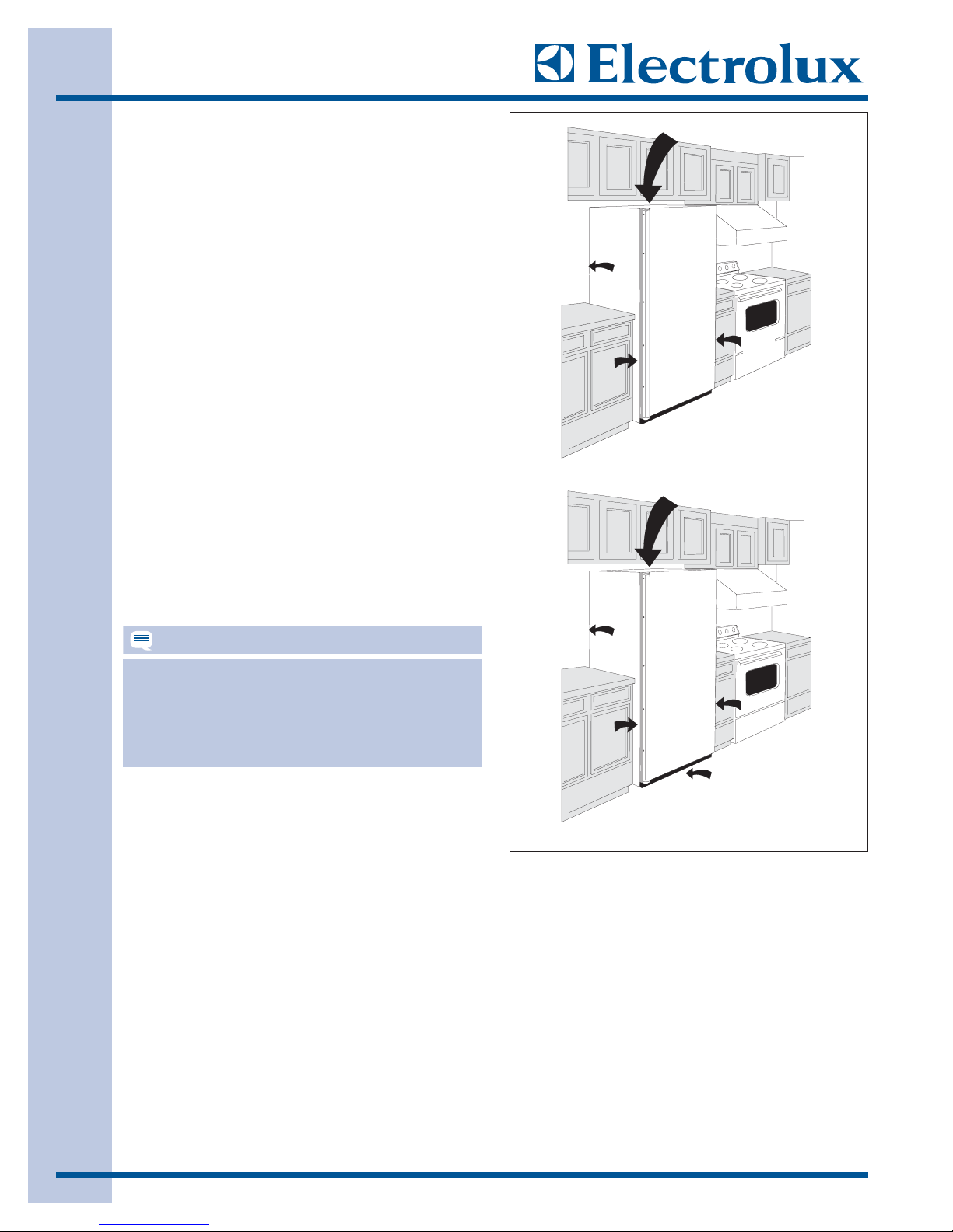
1”Air Space
1”
3/8”
3/8”
Installation for 17 cu. ft.
with dynamic condense
3”Air Space
NOTE
3”
3”
3”
1”
Installation for 21 cu. ft.
without dynamic condenser

IInnssttaallllaattiioonn IInnffoorrmmaattiioonn
2-5
EElleeccttrriiccaall IInnffoorrmmaattiioonn
These guidelines must be followed to ensure that
safety mechanisms in the design of this freezer will
operate properly.
Refer to the serial plate for correct electrical rating.
The power cord of the freezer is equipped with at
three-prong grounding plug for protection against
shock hazards. It must be plugged directly in to its
own properly grounded three-prong receptacle,
protected with a 15 amp time delay fuse or circuit
breaker. The receptacle must be installed in
accordance with the local codes and ordinances.
Consult a qualified electrician. Receptacles with
Ground Fault Circuit Interrupters (GFCI) are NOT
RECOMMENDED. DO NOT USE AN EXTENSION
CORD OR AN ADAPTER PLUG.
If the voltage varies by 10 percent or more, freezer
performance may be affected. Operating the freezer
with insufficient power can damage the motor. Such
damage is not covered under the warranty. If you
suspect your voltage is high or low, consult your
power company for testing.
To prevent the freezer from being turned off
accidentally, do not plug the unit in to an outlet
controlled by a wall switch or pull cord.
Do not pinch, knot, or bend the power cord in any
manner.
WARNING
NNEEVVEERR UUNNPPLLUUGG TTHHEE FFRREEEEZZEERR BBYY PPUULLLLIINNGG
OONN TTHHEE PPOOWWEERR CCOORRDD.. AALLWWAAYYSS GGRRIIPP TTHHEE
PPLLUUGG FFIIRRMMLLYY AANNDD PPUULLLL SSTTRRAAIIGGH
HTT OOUUTT
FFRROOMM TTHHEE RREECCEEPPTTAACCLLEE..
TTUURRNNIINNGG TTHHEE CCOONNTTRROOLL TTOO ““OOFFFF”” TTUURRNNSS
OOFFFF TTHHEE CCOOMMPPRREESSSSOORR BBUUTT DDOOEESS NNOOTT
DDIISSCCO
ONNNNEECCTT PPOOWWEERR TTOO OOTTHHEERR EELLEECCTTRRIICCAALL
CCOOMMPPOONNEENNTTSS..
IInnssttaallllaattiioonn IInnffoorrmmaattiioonn
2-6
LLeevveelliinngg
The freezer must have all bottom corners resting
firmly on a solid floor. The floor must be strong
enough to support a fully loaded freezer. It is VERY
IMPORTANT for your freezer to be level in order to
function properly. If the freezer is not leveled during
installation,the door/lid may be misaligned and not
close or seal properly, causing cooling, frost or
moisture problems.
TToo LLeevveell UUnniitt
After discarding crating screws and wood base, use
a carpenter’s level to level the freezer from front to
back. Adjust the plastic leveling feet in front, ½
bubble higher, so that the door closes easily when
left half way open.
DDoooorr RReemmoovvaall
For some installations it may be necessary to remove
the door to fit through the entrance of the installation
site.
To remove the door, follow the steps below.
1. Make sure electrical plug is disconnected from
the wall outlet.
2. Gently lay freezer on its back on a soft clean
surface.
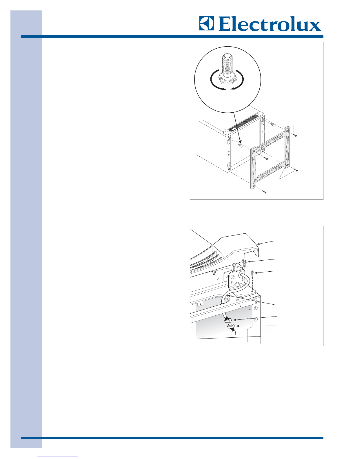
3. Lift plastic cover off upper hinge assembly.
4. Using a 3/8” open end wrench or socket, extract
screws securing the top hinge to the unit frame.
5. Remove the toe grille by grabbing the toe grille
at the top with both hands, then pull away from
the unit until toe grille disengages from the unit.
6. Reach under bottom of cabinet and disconnect
wire leads of door connector from the cabinet
connector.
7. Using a 3/8” open end wrench or socket,
extract screws securing the bottom hinge to the
unit frame. Use a phillips head screwdriver to
extract the remaining screw from the bottom
hinge assembly.
8. Lift the door assembly off of the unit frame.
Tu r n
Right To
Lower
Tu r n
Left To
Raise
Plastic
Leveling F eet
Crating
Screw
Discard The (4) Crating
Screws And Wood Base
Grille/ Kickplate
Hinge Bolt
Hinge Screw
Wire
Door Connector
Cabinet Connector
2-7
WWaatteerr SSuuppppllyy
The automatic ice maker requires a permanent water
supply to function correctly. During installation,
establish this water supply by connecting a copper
tube from the household water system to a valve at
the rear of the freezer.
WWhhaatt yyoouu wwiillll nneeeedd::
• Access to a cold water line with pressure of 20120 psi. (System supplied with cold water only.)
• Copper tubing with ¼inch (6.4mm) Outside
Diameter (OD). Length for this tubing is the
distance from the rear of the freezer to your
house hold water supply line plus seven feet
(2.1 meters).
• A shut-off valve for the connection between the
household water line and the freezer supply line.
Do not use a self-piercing shut-off valve.
• A compression nut and ferrule (sleeve) for the
water supply connection at the rear of freezer.
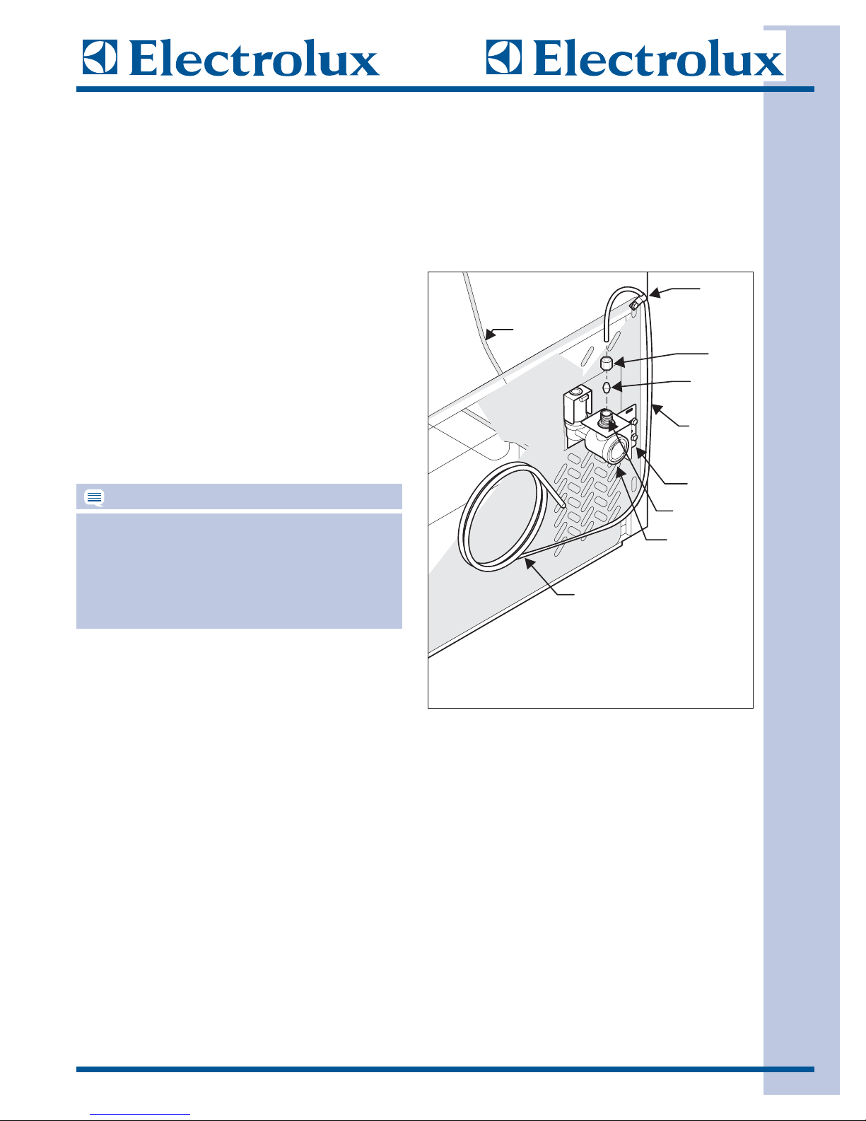
TToo ccoonnnneecctt tthhee wwaatteerr ssuuppppllyy ttoo tthhee rreeaarr ooff tthhee
ffrreeeezzeerr::
1. Ensure that the freezer is not plugged in.
2. Flush the supply line until water is clear by
placing the end of the copper tube in a sink or
bucket and opening the shut-off valve. Then turn
off water supply at valve.
3. Unscrew the plastic cap from the water valve
inlet at the rear of the freezer. Discard the cap.
4. Slide the brass compression nut, then the ferrule
(sleeve) onto copper tube.
5. Push the copper tube into water valve inlet as far
as it will go (¼ inch).
6. Slide the ferrule (sleeve) into valve and finger
tighten the compression nut onto valve. Tighten
another half turn with a wrench. Do not
over-tighten.
7. Secure the copper tube to your freezer’s rear
panel with a steel clamp and screw (See
Illustration).
8. Coil the excess copper tubing (about 2½ turns)
Behind your freezer as shown. Arrange
coiled tubing to avoid vibration or wear against
other surfaces.
9. Open water supply shut-off valve and tighten
any connections that leak.
10. Reconnect power to freezer.
11. Turn icemaker on and lower ice level arm to start
icemaker operation.
NOTE
KKiitt ## 55330033991177995500 iiss aavvaaiillaabbllee ffrroomm yyoouurr ddeeaalleerr
tthhaatt pprroovviiddeess aallll mmaatteerriiaallss ffoorr aa wwaatteerr ssuuppppllyy
iinnssttaallllaattiioonn,, iinncclluuddiinngg 2255 ffeeeett ooff ccooppppeerr ttuubbiinngg,, aa
ssaaddddllee ttyyppee sshhuuttooffff vvaallvvee,, ((22)) 11//44”” bbrraassss
ccoommpprreessssiioon
n nnuuttss,, ((22)) ffeerrrruulleess//sslleeeevveess aanndd ffuullll
iinnssttrruuccttiioonnss..
Steel
p
Plastic Water Tubing
to Ice Maker
Fill Tu be
Copper water line
from household water supply
Clam
Brass
Compression
Wa
Water Valve
Nut
Ferrule
(Sleeve)
Coppe r
water
lin
ter
alve
V
Bracke t
Valve Inlet
e
(Include enough tubing in loop
to allow moving freezer out
for cleaning)
2-8
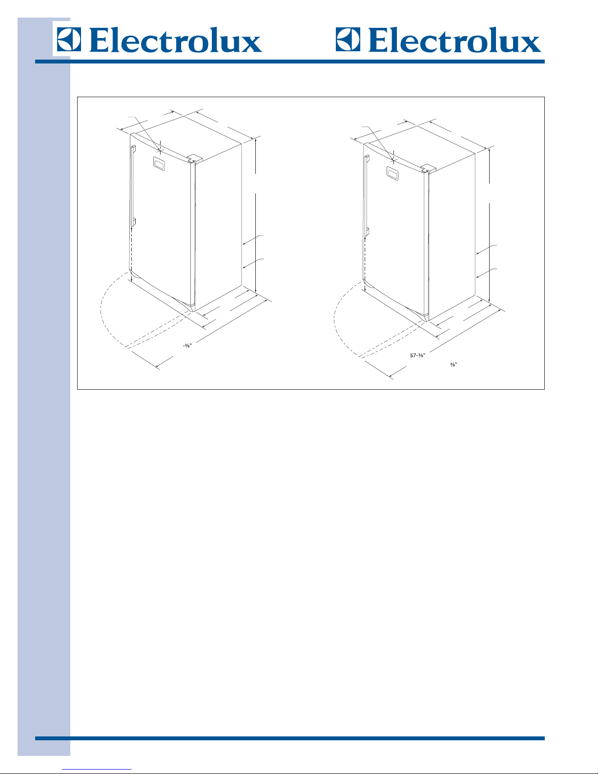
UUnniitt DDiimmeennssiioonnss
EEIILLFFUU2211GG SS
Unit Dimensions
EEIILLFFUU1177GG SS
Unit Dimensions
Overall depth at center
of arc 29-½”
28 ½”
C
L
32”
5
”
70- min.
8
∕
5
”
71- max.
∕8
Water line
inlet location
(left bottom rear)
Power cord
location
(right bottom rear)
Overall depth at center
of arc 27-½”
26½”
C
L
32”
65-½” min.
66-½” max.
Water line
inlet location
(left bottom rear)
Power cord
location
(right bottom rear)
31-¼”
59
(with doors 90˚ open)
26 -¼”
Note:
To allow for proper airow,
3”minumum
airspace required on each
side, with 1” at back and top
with 1” at bottom.
surrounding
(with doors 90˚ open)
24-¼”
29-¼”
Note:
To allow for proper airow,
airspace required on each
side, with 1” at back and top.
minumum
surrounding

EElleeccttrroonniicc CCoonnttrrooll
3-1
SSeeccttiioonn 33
EElleeccttrroonniicc CCoonnttrrooll
EElleeccttrroonniicc CCoonnttrrooll
3-2
EElleeccttrroonniicc TTeemmppeerraattuurree CCoonnttrrooll
The electronic temperature control is located on the freezer door. Temperature is factory preset to provide
satisfactory food storage temperatures. Refer to the SETTING FREEZER CONTROL Quick Reference Guide
below for more details.
NNOOTTEE::
The unit can reach as low as -35 degrees during the Fast Freeze Mode but ideally the mode is for
initial startup and the addition of product during restock.
NNOOTTEE::
Standard Ice Maker Production; 3.5-4 lbs/24hrs.
NNOOTTEE::
A more in depth description of the alarms is given on page 3-4.
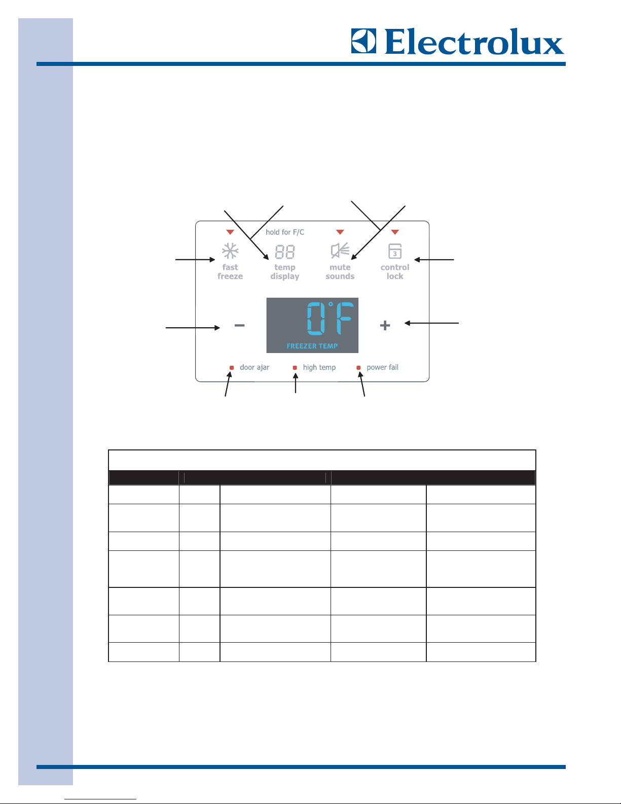
SETTING FREEZER CONTROL
Press to start or
cancel the fast
freeze feature.
Press to
decrease the
temperature
setting
Press and
hold for 3
seconds to
toggle F or C
in the display.
Indicates the
door has been
open 5 minutes
or more.
Turns the
temperature
display ON or
OFF.
Indicates the
temperature was
above +23°F ( -9°C)
for at least one
hour.
Press to
mute
audible
alarms.
Indicates the
power was
interrupted.
ALARM FUNCTION TABLE
Press to turn the
sounds ON or OFF.
When the LED is ON,
the sounds are muted.
Press and hold
for 3 seconds to
start or cancel
control lock.
Press to
increase the
temperature
setting
Display Priority Visual Alarm Alarm Status Action(s) Required
“HI” 3 “HI Temp” LED ON and
Alternating “E1”
and temperature
Alternating “CE”
and temperature
Alternating “E2”
and temperature
Actual
Temperature
Set Temperature 5
mute sounds LED ashes
2
mute sounds LED ashes; 1
second set temperature, 1
second “E1”
1
mute sounds LED ashes; 1
second set temperature, 1
second “CE”
4
mute sounds
second set temperature, 1
second “E2”
6
power fail LED on and mute
sounds
door ajar
sounds
LED ashes
LED on and
LED ashes
LED ashes; 1
mute
Freezer temperature
over the safe limit
Fail Safe Mode Check thermistor status
Communication Error Check connection between
Stuck Key Error Check membrane keys.
Cabinet greater than 10
degrees over the SET
TEMP. at power up.
Door open for more than
5 minutes
Press the mute sounds key
to stop the audible alarm
Press the mute sounds key
to stop the audible alarm
UI and ECU. Press the mute
sounds key to stop the
audible alarm
Press the mute sounds key
to stop the audible alarm
Press the mute sounds key
to stop the audible alarm
Press the mute sounds key
to stop the audible alarm

EElleeccttrroonniicc CCoonnttrrooll
3-3
NNoorrmmaall OOppeerraattiioonn
The user can select any temperature setting from -10°F to 10°F (-24°C to -12°C). Press the plus (
++))
key to
increment or the minus (
--
) key to decrement the temperature setting by one degree each key press. If a key
is not pressed within 3 seconds, the confirmation tone sounds and the set temperature blinks once before
changing to the new temperature setting. The display turns off 10 seconds later.
If the temperature display is OFF, the first press of ++or --key displays the current temperature setting. Then
pressing the ++or --will change the current setting. If the temperature display is ON, the first press of the ++or
--
will change the current setting by one degree.
The OFF setting is the position past the 10°F setting. A confirmation tone is sounded when switching to OFF
position. In the OFF position, all functions (compressor, defrost, and alarms) will be disabled except the light
control. When a temperature alarm condition is present and the set temperature is changed to the OFF
setting, the visual and audible alarms end.
TTeemmppeerraattuurree DDiissppllaayy
Press the
tteemmpp ddiissppllaayy
key to toggle temperature display ON or OFF. The default setting is OFF.
The acceptance tone sounds when the option is changed. The "FREEZER TEMP" LED on the display is
always ON.
TTeemmppeerraattuurree SSccaallee
Press and hold the
tteemmpp ddiissp
pllaayy
key for 3 seconds to switch between degrees F and degrees C. The
confirmation tone sounds after the 3 seconds. Initial default setting is Fahrenheit. Temperature displayed is
rounded to the nearest whole number.
If the temperature display is OFF, the display turns on and displays the set temperature and the change in
temperature scale. The display returns to OFF state after 3 seconds. If the temperature display is ON, the
temperature scale change is visible.
FFaasstt FFrreeeezzee
Engagement of the fast freeze function turns the compressor on for 72 hours. The fast freeze LED is enabled
when fast freeze is engaged and the acceptance tone sounds. The
ffaasstt ffrreeeezzee
key toggles the state ON or
OFF. The set temperature is displayed if temp display state is ON. The user is allowed to change the set
temperature while in fast freeze mode. The new set temperature will be used when the fast freeze cycle is
complete. Defrost will function normally during fast freeze. Fast freeze will not engage if the temperature
setting is "OFF". If fast freeze is activated during defrost, the LED will turn on but the compressor will not
come on until after the defrost cycle is completed. The freezer returns to the previous temperature setting
after the 72 hours. Manual defrost is not available while in fast freeze mode.
CCoonnttrrooll LLoocckk
Press and hold the
ccoonnttrrooll lloocckk
key for three seconds to activate or deactivate the freezer control lockout
feature which prevents user key entries. After the three seconds, the confirmation tone sounds and the
control lock LED will be displayed indicating that the control is locked. If a key is pressed while locked, the
control lock LED will flash twice and the invalid tone will sound. If an alarm occurs while in the locked mode,
the mute sounds key will be enabled to mute the alarm. When the lockout is deactivated, the control lock
LED will turn off.
MMuuttee SSoouunnddss
The
mmuuttee ssoouunnddss
key will enable or disable the audible sounds, i.e. key acceptance and confirmation tones.
The default state is mute sounds OFF and the corresponding LED is OFF. When you press
m
muuttee ssoouunnddss
to
enable mute feature, the acceptance key tone does not sound. When you press
mmuuttee ssoouunnddss
to disable mute
option, the acceptance key tone does sound. When you turn ON the mute sounds, the mute sounds LED
turns ON and all tones except alarms are eliminated. When the tones have been muted, the audible alarms
will still operate normally. The mute sounds key is also used for muting audible alarms.

EElleeccttrroonniicc CCoonnttrrooll
3-4
AAllaarrmmss
TTeemmppeerraattuurree AAllaarrmm
If the temperature of the cabinet remains above alarm activation temperature of 23.0°F +/- 3 F° (-5°C +/- 2°C)
for more than 1 hour, the high temp LED will turn ON, mute sounds LED will flash, the display will show "HI",
and the buzzer sounds the alarm tones. "HI" will continue to be displayed until the
mmuuttee ssoouunnddss
key is
pressed even if cabinet temperature decreases. The highest temperature will display for 10-seconds. Next,
the freezer will display the set temperature if cabinet temperature is not above the upper control limit. If the
cabinet temperature is above the upper control limit, the actual cabinet temperature will be displayed until the
set temperature is reached. The display will not turn off until the temperature is below the alarm temperature.
PPoowweerr FFaaiill AAllaarrmm
The red power fail LED will illuminate when the microprocessor initiates and the cabinet temperature is greater
than 10°F over the set temperature. The current temperature will be displayed and blinking. To acknowledge
the alarm, press the
mmuuttee ssoouunnddss
key. The audible alarm and power fail LED will then turn OFF. If the temp
display is OFF, the display will turn OFF 10 seconds after the alarm is cleared.
DDoooorr AAjjaarr AAllaarrmm
When the door is left open for 5 or more minutes, the alarm sounds. The door ajar LED turns ON. The
display will not change. Close the door or press the
mmuuttee ssoouunnddss
key to turn the audible alarm off. The door
ajar LED remains on until the door is closed.
CCoommmmuunniiccaattiioonn EErrrroorr
If a communication error occurs, the freezer will operate in "Fail Safe Mode". The display will alternate
between "CE" and set temperature in 1 second intervals. The mute sounds LED flashes. Check connection
between UI & ECU. Press the
mmuuttee ssoouunnddss
key to stop the audible alarm. No features will activate during a
communication error because the error will prevent proper operation.
TThheerrmmiissttoorr EErrrroorr
If a thermistor error occurs, the freezer will operate in "Fail Safe Mode". The display will alternate between
"E1" and set temperature in 1 second intervals. The mute sounds LED flashes. Check the thermistor status.
Press the
mmuuttee ssoouunnddss
key to stop the audible alarm.
SSttuucckk KKeeyy EErrrroorr
If a key is stuck, the freezer will maintain the current set temperature. The display will alternate between "E2"
and set temperature in 1 second intervals. The mute sounds LED flashes. Check membrane keys. Try
pressing mute sounds key to stop the audible alarm. The audible indication times out in 30 seconds.
FFaaiill SSaaffee M
Mooddee
When the unit goes into Fail Safe mode for a communications or thermistor error, the compressor will run
continuously.
EElleeccttrroonniicc CCoonnttrrooll
3-5
DDeeffrroosstt MMooddee
All models have an automatic defrost mode. Defrost will not engage if the control is in "OFF" position. When
defrost is manually initiated or terminated, an audible confirmation beep will occur.
DDeeffrroosstt TTiimmiinngg
After each 12 hours of accumulated compressor run time, a 30 minute defrost cycle is automatically engaged.
Before initiating the defrost cycle, the compressor is turned off. The freezer will exit defrost mode after 30
minutes and start cooling to maintain the previous control setting.
MMaannuuaall DDeeffrroosstt
Changing defrost states has precedence over normal run mode. Defrost can be toggled ON or OFF. Each
time defrost mode is changed, it will reset the compressor run time. Defrost state can be changed by
pressing and holding both
ffaasstt ffrreeeezzee
and
mmuuttee ssoouunnddss
keys simultaneously for 3 or more seconds.
The confirmation tone will sound to confirm that the state has changed and "dEF" will display for 3 seconds.
If the display is OFF, display returns to OFF state after 3 seconds. The user is allowed to change the set
temperature while in manual defrost. The new set temperature will be used when the defrost cycle is
complete. Diagnostic mode is not available while in manual defrost.
SShhoowwrroooomm M
Mooddee
Showroom mode allows a sales person to demonstrate the freezer features without turning the compressor on
or going through defrost cycles. Set the control to OFF position. Press and hold the + and - keys for 3
seconds to initiate show room mode. The display will show "SS" displaying for 3 seconds and the
confirmation tone will sound. All keys should operate normally during showroom mode. The cabinet light will
operate during showroom mode but the compressor and defrost heater will remain OFF. Set the control to
OFF and press and hold the + and - key for 3 seconds to end the showroom mode. No alarms will occur
during showroom mode. The showroom mode is automatically exited after a power failure.
TTeesstt MMooddee
To initiate "Test Mode" the J4 pins should be shorted before power up. All LED segments will illuminate for the
duration of 2 seconds. Each key that is pressed on the control will cause an LED to illuminate and stay
illuminated while in this mode. A numeric segment will be illuminated in each display with each key press. To
test communication, TX would need to be connected to RX. Remove power to exit the test mode.
Press the
ffaasstt ffrreeeezzee
key to illuminate the fast freeze LED.
Press the
tteemmpp ddiissppllaayy
key to illuminate the high temp LED.
Press the
mmuuttee ssoouunnddss
key to illuminate the mute sounds LED.
Press the
ccoonnttrrooll lloocckk
key to illuminate the control lock LED.
Press the (minus) "--" key to illuminate the door ajar LED.
Press the (plus) "++" key to illuminate the power fail LED.
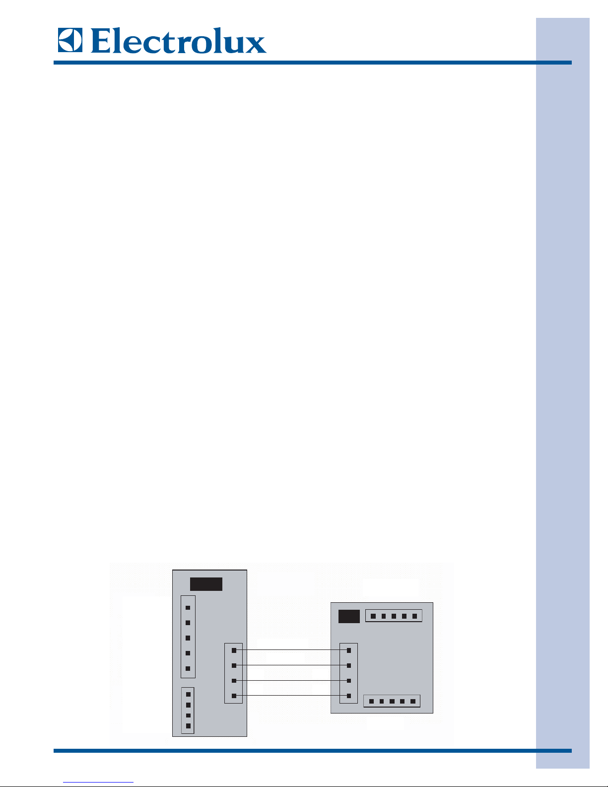
ECU
Neutral Input
Light Out
Programming
Header
UI
Heater Out
Comp. Out
Line Input L1
Thermistor
Door Switch
TX
RX
5V Power
Ground
RX
TX
Keypad
EElleeccttrroonniicc CCoonnttrrooll
3-6
SSeerrvviiccee DDiiaaggnnoossttiicc MMooddee
IInniittiiaattee SSeerrvviiccee MMooddee
The service technician should set the temperature to 0 F, then press and hold both the ++and --keys
simultaneously for 3 seconds.
When the diagnostics mode is entered, the number "88" is displayed and the confirmation tone is sounded.
The status information will be displayed for 3 seconds and then return to the diagnostics indicator.
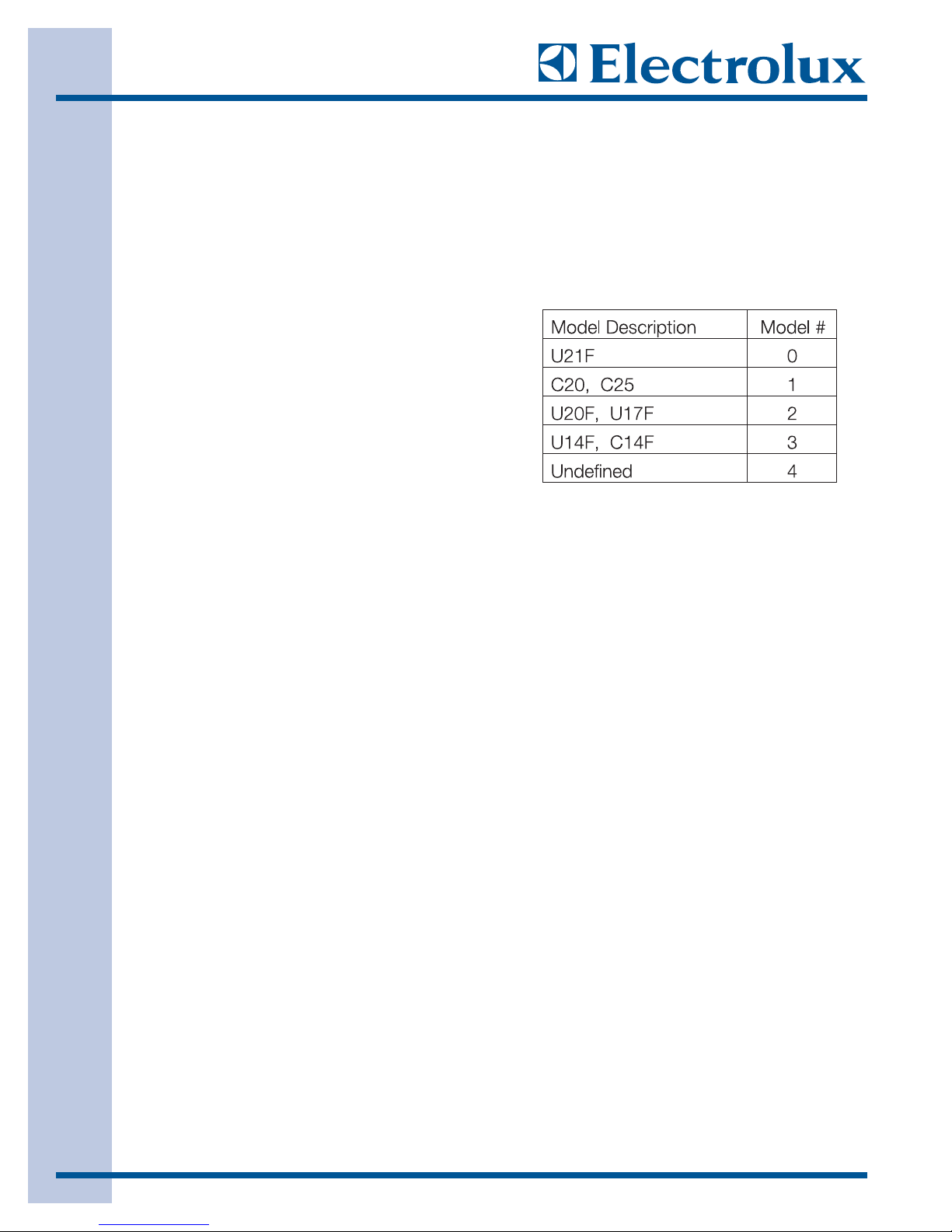
MMooddeell IIddeennttiiffiiccaattiioonn
Press the plus (++) key to display the model number.
Once you have displayed the model ID, press and hold
the plus (++) and
ffaasstt ffrreeeezzee
keys for 3 or more seconds
to select the option to change the model ID. The model
ID will increment or decrement by pressing the ++or
--
key. The model ID can be saved immediately by
pressing
mmuuttee ssoouunnddss
key.
SSooffttwwaarree VVeerrssiioonn
Press the
ffaasstt ffrreeeezzee
key to display the production software version for the model. (The limitation is 00 - 99
production software versions per model.) The minus and 2 digit version number "-xx" is displayed.
DDoooorr SSwwiittcchh SSttaattuuss
Press the "--" key to display the door switch status.
If the door switch is open, the letter "
ddOO
" is displayed.
If the door switch is closed, the letter "
ddCC
" is displayed.
TThheerrmmiissttoorr SSttaattuuss
Press the mute sounds key to display the thermistor status.
If the thermistor is operating properly, the characters "
-- --
" are displayed.
If the thermistor is open, the letter "
ttOO
" is displayed.
If the thermistor is shorted, the letter "
ttSS
" is displayed.
The thermistor status is not updated in showroom mode. The characters "
-- --
" are always displayed
RReesseett FFaaccttoorryy DDeeffaauullttss
Press the
ffaasstt ffrreeeezzee
key while the software version is displayed to reset all EEPROM values to the factory
defaults. The model ID will not be affected. The user interface will exit diagnostics mode and automatically
restart in normal power up operation.
EExxiitt DDiiaaggnnoossttiicc MMooddee
To exit service mode, the service technician should press and hold both the ++and --keys simultaneously for 3
or more seconds. The buzzer beeps at the end of 3 seconds.

4-1
RReeffrriiggeerraattiioonn SSyysstteemm
SSeeccttiioonn 44
RReeffrriiggeerraattiioonn SSyysstteemm

4-2
RReeffrriiggeerraattiioonn SSyysstteemm
NOTE
IInnssttrruuccttiioonnss ggiivveenn hheerree aarree ffuurrnniisshheedd aass aa
gguuiiddee.. PPeerrssoonnss aatttteemmppttiinngg ttoo uussee tthheessee
iinnssttrruuccttiioonnss ttoo mmaakkee rreeppaaiirrss ttoo tthhee sseeaalleedd
rreeffrriiggeerraattiioonn ssyysstteemm sshhoouulldd hhaavvee aa wwoorrkkiinngg
kknnoowwlleeddggee ooff rreeffrriiggeerraattiioonn aanndd
pprreevviioouuss ttrraaiinniinngg
oonn sseeaalleedd ssyysstteemm rreeppaaiirr,, aanndd aann EEPPAA cceerrttiiffiiccaa--
ttiioonn ffoorr sseerrvviicciinngg rreeffrriiggeerraattiioonn ssyysstteemmss..
NOTE
EElleeccttrroolluuxx ddooeess nnoott ppeerrmmiitt tthhee uussee ooff rreeccoovveerreedd
rreeffrriiggeerraanntt iinn tthhee sseerrvviicciinngg ooff oouurr pprroodduuccttss ffoorr
iin
n--wwaarrrraannttyy aanndd oouutt--ooff--wwaarrrraannttyy rreeppaaiirrss oorr ffoorr
pprroodduuccttss ccoovveerreedd bbyy sseerrvviiccee ccoonnttrraaccttss..
TThheerreeffoorree,, oonnllyy
nneeww rreeffrriiggeerraanntt oorr rreeffrriiggeerraanntt tthhaatt
hhaass bbeeeenn rreeccllaaiimmeedd bbaacckk ttoo nneeww ssppeecciiffiiccaattiioonnss
bbyy aa rreeffrriiggeerraanntt mmaannuuffaaccttuurreerr iiss ttoo bbee uusseedd..
IMPORTANT
EEffffeeccttiivvee JJuullyy 11,, 11999922,, tthhee UUnniitteedd SSttaatteess cclleeaann
aaiirr aacctt ggoovveerrnnss tthhee ddiissppoossaall ooff rreeffrriiggeerraannttss ssuucchh
aas
s RR--113344aa.. TThheerreeffoorree,, wwhheenn ddiisscchhaarrggiinngg oorr
ppuurrggiinngg tthhee sseeaalleedd ssyysstteemm uussee aann EEPPAA aapppprroovveedd
rreeffrriiggeerraanntt r
reeccoovveerryy ssyysstteemm aass oouuttlliinneedd iinn tthhee
ffiinnaall rruullee oonn tthhee pprrootteeccttiioonn ooff ssttrraattoosspphheerriicc
oozzoonnee aanndd rreeffrriiggeerraanntt rreeccyycclliinngg,, wwhhiicchh wwaass
ppuubblliisshheedd iinn tthhee FFeeddeerraall RReeggiisstteerr MMaayy 1144,, 11999933..
DDeeffiinniittiioonnss
RReeccoovveerryy::
To remove refrigerant in any condition from a
system and store it in an external container without
necessarily testing or processing it in any way.
RReeccyycclliinngg::
To clean refrigerant for reuse by oil separation and
single or multiple passes through devices, such as
replaceable core filter-driers, which reduce
moisture, acidity and particulate matter. This term
usually applies to procedures implemented at the
field job site or at a local service shop.
RReeccllaaiimm::
To reprocess refrigerant to new product
specifications by means which may include
distillation, will require chemical analysis of the
refrigerant to determine that appropriate product
specifications are met. This term usually implies
the use of processes or procedures available only
at a reprocessing or manufacturing facility.
SSaaffeettyy WWaarrnniinnggss
CCoommpprreessssoorr TTeessttiinngg
Whenever testing a compressor, extreme caution
should be used to prevent damaging the terminals.
A compressor with a damaged terminal or a
grounded winding can expel a terminal from its
insulated housing when the compressor is
energized. If this happens, a mixture of refrigerant
and oil will be released that could be ignited by an
external heat source (open flame, heater, etc.).
Also, if there is air in the system when this
happens, a spark at the compressor shell could
ignite the refrigerant and oil mixture.
CChhaarrggiinngg SSeeaalleedd SSyysstteemmss
Overcharging a refrigeration system with refrigerant
can be dangerous. If the overcharge is sufficient
to immerse the major parts of the motor and
compressor in liquid refrigerant, a situation has
been created which, when followed by a sequence
of circumstances can lead to the compressor shell
seam separating.
A hydraulic block occurs, preventing the
compressor from starting. This condition is known
as locked rotor. Electric current continues to flow
through the compressor motor windings which
become, in effect, electric resistance heaters.
The heat produced begins to vaporize the excess
refrigerant liquid causing a rapid increase in
system pressure. If the compressor protective
devices fail, the pressure within the system may
rise to extremes far in excess of the design limits.
Under these conditions, the weld seam around the
compressor shell can separate with explosive
force, spewing oil and refrigerant vapor which
could ignite.
To eliminate this exceedingly rare but potential
hazard, never add refrigerant to a sealed system.
If refrigerant is required, evacuate the existing
charge and recharge with the correct measured
amount of the refrigerant specified for the system.

1. All joints to be soldered must have proper fit.
Clearance between tubes to be soldered
should be from .001” to .006”. It is not
practical to actually measure this; however,
you do not want a dry fit or loose fit. Tubing
joints should overlap about the distance of
their diameter except for restrictor tubes,
which should be inserted 1.25”.
2. Clean all joint areas with fine steel wool or
preferably an abrasive cloth, such as grit cloth
No. 23 or Scotch-Brite.
3. Apply a thin film of liquid flux recommended
for silver soldering to surfaces to be joined and
to surfaces immediately adjacent to joint.
4. Align tubing so no stress is on joint. Do not
move tubing while solder is solidifying or leaks
will result.
5. Use a torch of adequate capacity so joint can
be quickly heated with a minimum of heat
travel to other points. Use a good grade of
silver solder.
6. Solder connections. If tubing is properly
cleaned and fluxed, solder will flow readily.
Use only enough solder to make a good bond.
7. Allow joint to cool, then wash exterior with
water to remove flux.
BBaassiicc CCoommppoonneennttss
The basic components of a refrigerator are a
compressor, condenser, evaporator, heat
exchanger (capillary tube and suction line), drier
and perimeter hot tube.
PPeerriimmeetteerr HHoott TTuubbee
To reduce the possibility of condensation forming
on the exterior of the cabinet in high humidity
areas, a perimeter hot tube (refrigerant tube) has
been installed in the unit. The perimeter tube
extends up the left side,across the top of the
freezer and down the right side into the filter drier.
When the compressor operates, warm refrigerant
flows through the primary condenser, then into the
primary hot tube, warming the cabinet front
exterior.
The perimeter hot tube is not replaceable. In the
unlikely event of a leak in the hot tube, a kit is
available to bypass the hot tube in the sealed
system. An electrical heater wire must be installed
within the tubing. Refer to the appropriate parts list
of the model being serviced for the correct kit part
number.
RReeffrriiggeerraanntt CCyyccllee
The refrigerant cycle is a continuous cycle that
occurs whenever the compressor is in operation.
Liquid refrigerant is evaporated in the evaporator
by the heat that enters the cabinet through the
insulated walls and by the heat from product load
and door openings. The refrigerant vapor is then
drawn from the evaporator, through the suction line
to the compressor. Compression raises the
pressure and temperature of the vapor in the
compressor and the vapor is then forced through
the discharge valve into the discharge line and into
the condenser. Air passing over the condenser
surface removes heat from the high pressure vapor
which then condenses to a liquid. The liquid
refrigerant then flows from the condenser to the
evaporator through the small diameter liquid line
(capillary tube). Before it enters the evaporator, the
liquid refrigerant is sub-cooled in the heat
exchanger by the low temperature suction vapor in
the suction line. When refrigerant is added, the
frost pattern will improve, the suction and
discharge pressures will rise, the condenser will
become hot and the wattage will increase.
4-3
RReeffrriiggeerraattiioonn SSyysstteemm
WWEEAARR AAPPPPRROOVVEEDD SSAAFFEETTYY GGLLAASSSSEESS WWHHEENN
WWOORRKKIINNGG WWIITTHH OORR OONN AANNYY PPRREESSSSUURRIIZZEEDD
SSYYSSTTEEMM OORR EEQQUUIIPPMMEENNTT.. HHAAVVEE AANN
A
APPPPRROOVVEEDD DDRRYY TTYYPPEE FFIIRREE EEXXTTIINNGGUUIISSHHEERR
HHAANNDDYY WWHHEENN UUSSIINNGG AANNYY TTYYPPEE OOFF GGAASS
OOPPEERRAATTEEDD TTOORRCCHH..
DDuurriinngg aapppplliiccaattiioonn ooff hheeaatt,, uussee wweett ccllootthhss ttoo
pprreevveenntt hheeaatt ffrroomm ccoonndduuccttiinngg ttoo aarreeaass ootthheerr
tthhaann tthhee ssoollddeerreedd jjooiinntt.. UUssee aa sshheeeett ooff mmeettaall oorr
ttoorrcchh gguuaarrdd ppaadd aass aa hheeaatt ddeefflleeccttoorr ttoo kkeeeepp
ffllaammee aawwaayy ffrroomm i
innffllaammmmaabbllee mmaatteerriiaallss aanndd
ppaaiinntteedd ssuurrffaacceess..
WARNING
CAUTION

4-4
RReeffrriiggeerraattiioonn SSyysstteemm
LLooww//HHiigghh SSiiddee LLeeaakk oorr UUnnddeerrcchhaarrggee
A loss of refrigerant can result in any of the
following:
1. Excessive or continuous compressor
operation.
2. Above normal freezer compartment
temperature.
3. A partially frosted evaporator (depending on
amount of refrigerant loss).
4. Below normal freezer compartment
temperature.
5. Low suction pressure (vacuum).
6. Low wattage.
The condenser will be “warm to cool”, depending
on the amount of refrigerant lost.
In the case of a low side refrigerant leak resulting
in complete loss of refrigerant, the compressor will
run but will not refrigerate. Suction pressure will
drop below atmospheric pressure and air and
moisture will be drawn into the system saturating
the filter drier.
If there is reason to believe the system has
operated for a considerable length of time with no
refrigerant and the leak occurred in the low side of
the system, excessive amounts of moisture may
have entered the system. In such cases the two
stage service Dryer Filter part number 5303918288
and vacuum procedure listed under Refrigerant
Leaks need to be followed to prevent repetitive
service.
If a slight undercharge of refrigerant is indicated
and no leak can be found after a thorough leak
test, the charge can be corrected without changing
the compressor.
If a high side leak is located and some refrigerant
remains in the system it is not necessary to
change the compressor.
TTeessttiinngg ffoorr RReeffrriiggeerraanntt LLeeaakkss
If the system is diagnosed as short of refrigerant
and the system has not been recently opened,
there is probably a leak in the system. Adding
refrigerant without first locating and repairing the
leak or replacing the component will not
permanently correct the difficulty. The leak must be
found. Sufficient refrigerant may have escaped to
make it impossible to leak test effectively. In such
cases, add a ¼” line piercing valve to the
compressor process tube. Add sufficient
refrigerant vapor to increase the pressure to 40 to
50 lb. per sq. in. Check the low side for leaks.
Run the compressor 2 or 3 minutes and check the
high side for leaks. Recover refrigerant using an
EPA approved recovery system.
CCoommpprreessssoorr RReeppllaacceemmeenntt
To check for contamination, obtain oil sample from
old compressor.
1. If the oil has burned odor, but no color change
or residue — follow instructions on page 4-6
“Installing A New Compressor”.
2. If oil has a burned odor and a sugar or gritty
feel as well as showing signs of contamination
(dark color), follow instructions in next section,
To Flush The System. Remove as much of
contamination as possible from system before
installing new compressor and filter-drier.
NOTE
TThhee lliinnee ppiieerrcciinngg vvaallvvee ((ccllaammpp--oonn ttyyppee)) sshhoouulldd
bbee uusseedd ffoorr tteesstt ppuurrppoosseess oonnllyy.. IItt mmuusstt bbee
rreemmoovveedd ffrroomm ssyysstteemm aafftteerr iitt hhaass sseerrvveedd iittss
ppuurrppoossee..
NOTE
IItt iiss rreeccoommmmeennddeedd tthhaatt ssyysstteemm bbee fflluusshheedd wwiitthh
ddrryy NNiittrrooggeenn.. HHoowweevveerr,, iiff rreeffrriiggeerraanntt iiss uusseedd ttoo
fflluus
shh tthhee ssyysstteemm yyoouu mmuusstt llooookk aatt tthhee sseerriiaall
ppllaattee ttoo sseeee wwhhaatt ttyyppee ooff rreeffrriiggeerraanntt iiss uusseedd iinn
tthhee ssyysstteem
m.. TThhiiss iiss tthhee oonnllyy rreeffrriiggeerraanntt tthhaatt ccaann
bbee uusseedd ttoo fflluusshh tthhee ssyysstteemm aanndd iitt mmuusstt bbee
rreeccoovveerreedd..
CAUTION
NNEEVVEERR iinnssttaallll aa nneeww ccoommpprreessssoorr wwiitthhoouutt ffiirrsstt
cchheecckkiinngg ffoorr ppoossssiibbllee ssyysstteemm ccoonnttaammiinnaattiioonn..
4-5
RReeffrriiggeerraattiioonn SSyysstteemm
TToo FFlluusshh TThhee SSyysstteemm
TToo UUssee DDrryy NNiittrrooggeenn TToo FFlluusshh TThhee SSyysstteemm::
1. Remove compressor and filter-drier. Connect
process coupling to outlet tube of condenser.
2. Fasten cloth over other end of coil to prevent
old oil from spraying over room.
3. Connect hand shut-off valve on flushing hose
to process coupling.
4. Slowly open hand shut-off valve and allow
nitrogen to flow through condenser until
discharge is clear.
5. Disconnect cap tube from evaporator. Flush
evaporator in same manner as condenser.
6. Flush cap tube. This is only possible if you
have proper service valve adapter.
7. Reassemble system.
CAUTION
DDOO NNOOTT eexxcceeeedd 330000 PPSSIIGG..
CAUTION
UUssee eexxttrreemmee ccaarree wwhheenn uussiinngg DDrryy NNiittrrooggeenn ttoo
fflluusshh ssyysstteemmss.. PPrreessssuurree iinn nniittrrooggeenn ccyylliinnddeerr
ccoouulldd bbee a
ass hhiigghh aass 22000000 ppssii.. NNiittrrooggeenn ccyylliinnddeerr
mmuusstt bbee eeqquuiippppeedd wwiitthh aapppprroovveedd pprreessssuurree
rreegguullaattoorr aanndd pprreessssuur
ree rreelliieeff vvaallvvee.. EEnnssuurree tthhaatt
yyoouurr hhoosseess hhaavvee aaddeeqquuaattee rraattiinnggss ffoorr pprreessssuurree
iinnvvoollvveedd aanndd tthhaatt aallll ooff yyoouurr eeqquuiippmmeenntt iiss iinn
ggoooodd ccoonnddiittiioonn.. TThhee eenndd ooff tthhee fflluusshhiinngg hhoossee oonn
tthhiiss ttaannkk rreegguullaattoorr mmuusstt bbee eeq
quuiippppeedd wwiitthh aa
hhaanndd sshhuutt--ooffff vvaallvvee ((RRoobbiinnaaiirr NNoo.. 4400338800)).. CClloossee
hhaanndd sshhuutt--ooffff vvaallvvee aanndd aaddjjuusstt nniittrrooggeenn rreegguullaattoorr
ttoo ccoorrrreecctt pprreessssuurree bbeeffoorree pprroocceeeeddiinngg wwiitthh
fflluusshhiinngg pprroocceedduurree..
TToo UUssee RReeffrriiggeerraanntt TToo F
Flluusshh TThhee SSyysstteemm::
1. Disconnect the suction and discharge lines
from the compressor and remove the
filter-drier. Connect process coupling to outlet
and inlet tube of condenser.
2. Connect hose to outlet process coupling and
charging cylinder. Connect another hose to
inlet coupling and recovery system.
3. Open charging cylinder and allow refrigerant to
flow through condenser until discharge into
bag is clear.
4. Disconnect capillary tube from evaporator.
Flush evaporator in same manner as
condenser.
5. Flush cap tube. This is only possible if you
have proper service valve adapter.
6. Reassemble system.
NOTE
TThhee lliinnee ppiieerrcciinngg vvaallvvee ((ccllaammpp--oonn ttyyppee)) sshhoouulldd
bbee uusseedd ffoorr tteesstt ppuurrppoosseess oonnllyy.. IItt mmuusstt bbee
rreemmoovveedd f
frroomm ssyysstteemm aafftteerr iitt hhaass sseerrvveedd iittss
ppuurrppoossee..
CAUTION
DDOO NNOOTT eexxcceeeedd 115500 PPSSIIGG..
CAUTION
DDOO NNOOTT eexxcceeeedd 330000 PPSSIIGG..
CAUTION
RReeffrriiggeerraanntt uusseedd ffoorr fflluusshhiinngg mmuusstt bbee rreeccoovveerreedd
iinnttoo aa rreeccoovveerryy ssyysstteemm.. MMeetteerr aammoouunntt ooff
rreeffrriiggeerraanntt uusseedd ffoorr fflluusshhiinngg wwiitthh yyoouurr cchhaarrggiinngg
ccyylliinnddeerr.. DDOO NNOOTT OOVVEERRFFIILLLL TTHHEE BBAAGG..

A new compressor which is cold (e.g. after having
been kept in a cold service van) should be left to
warm to the surrounding temperature before the
plugs on the compressor connections are
removed. This will help prevent condensation from
forming in the oil and the compressor. Also, avoid
opening the system when any of the components
or lines are cold.
1. Disconnect electrical supply to refrigerator.
2. Remove compressor access panel.
3. Remove all components needed to pull the
compressor assembly from the unit.
4. Pull compressor assembly straight out.
5. Recover refrigerant by using EPA approved
recovery system.
6. Remove leads from compressor motor
terminals.
7. Remove mounting clips and washers.
8. After refrigerant is completely recovered, cut
suction and discharge lines as close to
compressor as possible. Leave only enough
tubing to pinch off and seal defective
compressor. Plug or tape any open system
tubing to avoid entrance of moisture and air
into system. Remove inoperable
compressor and transfer mounting parts to
new compressor.
9. Install new compressor in exact same manner
as original compressor.
4-6
RReeffrriiggeerraattiioonn SSyysstteemm
NOTE
RReelleeaassee hhoollddiinngg cchhaarrggee ((rreelleeaassee sslloowwllyy ttoo aavvooiidd
ooiill ddiisscchhaarrggee)) oonn nneeww ccoommpprreessssoorr ttoo eennssuurree
tthheerree iiss
nnoo lleeaakk iinn sseeaamm oorr ttuubbiinngg.. RReeiinnssttaallll
rruubbbbeerr pplluugg..
NOTE
TThhee ffoolllloowwiinngg iinnssttrruuccttiioonnss aarree ggeenneerraalliizzeedd ttoo
hheellpp tthhee tteecchhnniicciiaann uunnddeerrssttaanndd tthhee pprroocceedduurreess
ooff sseeaalleedd ssyysstteemm rreeppaaiirrss.. SSeeee SSeeccttiioonn 55
CCoommppoonneenntt TTeeaarrddoowwnn oonn tthhee eexxaacctt sstteeppss ooff
aacccceessssiinngg tthhee ccoommppoonneennttss o
off tthhee rreeffrriiggeerraattiioonn
ssyysstteemm..
NOTE
IIff llooww--ssiiddee pprroocceessss ttuubbee iiss ttoooo sshhoorrtt,, ssiillvveerr
ssoollddeerr ffoouurr iinncchh ppiieeccee ooff ttuubbiinngg oonnttoo pprroocceessss
ttuubbee aat
t tthhiiss ttiimmee..
IInnssttaalllliinngg aa NNeeww CCoommpprreessssoorr
Replacement of compressor and installation of
filter-drier must be done in a continuous sequence
so system is exposed to atmosphere no longer
than necessary.
All replacement compressors are shipped with
rubber plugs in the suction, discharge and process
tubes and contain the correct oil charge and a
holding charge of inert gas. Compressors have a
low-side process tube attached to the compressor
shell. A high-side process tube is attached to the
filter-drier.
Replacement compressors for refrigerator may
have an oil cooler even if the original compressor
did not. If the product is not equipped for an oil
cooler, leave the plastic caps in place and install
the compressor connecting only to the suction and
discharge lines of the new compressor.
Before installing the replacement compressor
remove the discharge plug and check for the pop
sound of the inert gas leaving the compressor.
If the compressor checks OK, reinstall the plug.
Do not remove any of the plugs again until the
compressor is in position and you are ready to
braze the lines.
NOTE
EEnnttiirreellyy nneeww ccoommpprreessssoorrss hhaavvee bbeeeenn ddeevveellooppeedd
oorr uussee wwiitthh RR--113344aa aanndd EEsstteerr ooiill rreeffrriiggeerraattiioonn
ssyysstteemmss.
. BBootthh ccoommpprreessssoorr aanndd eelleeccttrriicc mmoottoorr
hhaavvee bbeeeenn mmooddiiffiieedd.. OOlldd ccoommpprreessssoorrss iinntteennddeedd
ffoorr RR--1122 rreeffrriiggeerra
anntt mmuusstt nnoott bbee uusseedd ffoorr nneeww
ssyysstteemmss cchhaarrggeedd wwiitthh RR--113344aa..
CAUTION
DDOO NNOOTT uussee ccoommpprreessssoorr iiff yyoouu ddoo nnoott hheeaarr tthhiiss
ssoouunndd..
CAUTION
OOnn RR--113344aa ssyysstteemmss,, ccoommpprreessssoorr mmuusstt NNOOTT bbee
lleefftt ooppeenn ttoo aattmmoosspphheerree ffoorr mmoorree tthhaann 1100
mmiinnuutteess ttoo pprreevve
enntt mmooiissttuurree ccoonnttaammiinnaattiioonn ooff ooiill..
WARNING
DDOO NNOOTT OOPPEERRAATTEE RREECCIIPPRROOCCAATTIINNGG
CCOOMMPPRREESSSSOORR WWHHEENN CCHHAARRGGIINNGG LLIIQQUUIIDD
RREEFFRRIIGGEERRAANNTT IINNTTOO SSYYSSTTEEMM TTHHRROOUUGGHH IITTSS
PPRROOCCEESSSS TTUUBBEE..

CCoonnddeennsseerr RReeppllaacceemmeenntt
1. Disconnect electrical supply to refrigerator.
2. Remove compressor access panel.
3. Recover refrigerant by using EPA approved
recovery system.
4. Remove condenser fan mounting screws.
5. Unplug fan motor harness located in back of
fan motor.
6. Remove fan motor and fan blade.
7. After refrigerant is completely recovered,
disconnect inlet and discharge lines from
condenser.
8. Lift front of condenser and pull out of retainers
mounted to the drain pan.
9. Remove old condenser out the back of
cabinet.
10. Install replacement condenser.
11. Remove original filter-drier.
12. Install new filter-drier at condenser outlet.
13. Evacuate and charge the system using
recommended procedure described under
Evacuating and Recharging.
14. Reassemble unit.
4-7
RReeffrriiggeerraattiioonn SSyysstteemm
10. Reform both suction and discharge lines to
align with new compressor. If they are too
short, use additional lengths of tubing. Joints
should overlap 0.5” to provide sufficient area
for good solder joint. Clean and mark area
where tubing should be cut. Cut tubing with
tubing cutter. Work as quickly as possible to
avoid letting moisture and air into system.
11. Solder all connections according to soldering
procedure.
12. Remove original filter-drier.
13. Install new filter-drier at condenser outlet.
14. Evacuate and charge system using recommended procedure described under
Evacuating and Recharging.
15. Reconnect compressor terminal leads in
accordance with refrigerator wiring diagram.
16. Reassemble unit.
CAUTION
DDOO NNOOTT uunnbbrraazzee oolldd ffiilltteerr--ddrriieerr ffrroomm ssyysstteemm..
TThhiiss wwiillll vvaappoorriizzee aanndd ddrriivvee mmooiissttuurree ffrroomm
ddeessiiccccaanntt b
baacckk iinnttoo ssyysstteemm.. TThhee oolldd ffiilltteerr--ddrriieerr
sshhoouulldd bbee ccuutt oouutt ooff ssyysstteemm..
NOTE
TThhee ffoolllloowwiinngg iinnssttrruuccttiioonnss aarree ggeenneerraalliizzeedd ttoo
hheellpp tthhee tteecchhnniicciiaann uunnddeerrssttaanndd tthhee pprroocceedduurreess
ooff sseeaalleedd ssyysstteemm rreeppaaiirrss.. SSeeee SSeeccttiioonn 55
CCoommppoonneenntt TTeeaarrddoowwnn oonn tthhee eexxaacctt sstteeppss ooff
aacccceessssiinngg tthhee ccoommppoonneennttss o
off tthhee rreeffrriiggeerraattiioonn
ssyysstteemm..
 Loading...