

Electrolux EI30HI55KSA, EI36HI55KSB, EI48HI55KSB, EI30HI55KSB Owner’s Manual
Installation, Use & Care Guide
30"(76.2 cm)_ 36"(91.4 cm) and 48"(121.92 cm) Hood insert
Guide d'installation, utilisation
et d'entretien
30"(76.2 cm)_ 36"(91.4 cm) et 48"(121.92 cm) Doublure de Hotte
Guia de Instalacibn, Use y Cuidado
Campana de linea de 30"(76.2 cm), 36"(91.4 cm) y 48"(121.92 cm)
LI30FA Ed. 08/11
iiiiiiiiiiiiiiiiiiiiiiiiiiiiiiiiiiiiiiiiiiiiiiiiiiiiiiiiiiiiiiiiiiiiiiiiiiiiiii
Finding Information
Please read and save this guide
Thank you for choosing Electrolux, the new premium brand inhome appliances. This Use & Care Guide is
part of our commitment to customer satisfaction and product quality throughout the service life of your new
appliance.
We view your purchase as the beginning of a relationship. To ensure our ability to continue serving you,
please use this page to record important product information.
Keep a record for quick reference
Purchase date
Model number
Serial number (see picture for location)
Fortoll-free telephone support in the U.S. and Canada:
US.: 1.800.944.9044 / Canada: 1.800.265.8352
Foronline support and Internet product information visit http://www.electroluxappliances.com
Table of contents
Important Safety Instructions ................................ 3
List of materials .........................................................4
Electrical requirements ...........................................5
Location requirements ........................................... 6
Product dimensions .................................................6
Venting Requirements ...............................................7
Venting method& .......................................................................7
Install Hood Insert Internal
Blower Motor. .............................................................8
Remote Blower Motor Installation
into Hood Insert .........................................................10
Prepare the location ..................................................12
Install Hood Insert into Hood Cabinet ....................13
Make Electrical Power Supply
Connection to Hood Insert .......................................14
Complete Installation and Check Operation ........ 14
Hood Insert Use.........................................................15
Cleaning .......................................................................15
Warranty Information ................................................16
@2011 Electrolux Home Products, Inc. All rights reserved. Printed in Mexico
Impo ant Safety Instructions
Read allinstruclions before using this
appliance.
Save lhese instruclions for future
references
Approved for residenlial appliances
For residential use only
Do not attempt to install or operate your appliance
until you have read the safety precautions in this
manual. Safety items throughout this manual are
labeled with a WARNING or CAUTION based on the
risk type.
Important Safety Instructions
WARNING
PLEASE READ ENTIRE INSTRUCTIONS BEFORE PROCEEDING.
INSTALLATION MUST COMPLY WITH ALL LOCAL CODES.
IMPORTANT: Save these Instructions for the Local Electrical Inspector's use.
INSTALLER: Please leave these Instructions with this unit for the owner.
OWNER: Please retain these instructions for future reference.
Safety Warning: Turn off power circuit at service panel and lock out panel, before wiring this appliance.
Requirement: 120 VAC, 60 Hz. 15 or 20 A Branch Circuit
This symbol alerts you to
situations that may cause
serious body harm, death
or property damage.
This symbol alerts you to
situations that may cause
bodily injury or property
damage.
,m0ortantsafety,nstructions
ilililililililililililililililililililililililililililililililililililililililiREAD AND SAVE THESE INSTRUCTIONS
CAUTION
FOR GENERAL VENTILATING USE ONLY. DO NOT USE
TO EXHAUST HAZARDOUS OR EXPLOSIVE
MATERIALS OR VAPORS.
TO REDUCE THE RISK OF FIRE, ELECTRIC SHOCK,
OR INJURY TO PERSONS, OBSERVE THE
FOLLOWING:
A. Use this unit only in the manner intended by the
manufacturer. Ifyou have questions, contact the
manufacturer
B. Before servicing or cleaning the unit, switch power off
at service panel and lock service panel disconnecting
means to prevent power from being switched on
accidentally. When the service disconnecting means
cannot be locked, securely fasten a prominent warning
device, such as atag, to the service panel.
C. Installation Work and Electrical Wiring Must Be Done By
Qualified Person(s) In Accordance With all Aplicable
Codes & Standards, Including Fire-rated Construction.
D. Sufficient air is needed for proper combustion and ex
hausting of gases through the flue (Chimney) of fuel
burning equipment to prevent back- drafting. Follow
the heating equipment manufacturers guideline
and safety standards such as those published by
the National Fire Protection Association (NFPA),
the American Society for Heating, Refrigeration and Air
Conditioning Engineers (ASHRAE), and the local code
authorities.
E. When cutting or drilling into wall or ceiling, do not
damage electrical wiring and other hidden utilities.
F. Ducted systems must always be vented to the
outdoors.
Toreduce risk of fire and to properly exhaust air, be sure to
duct air outside - do not vent exhaust air into spaces within
walls, ceilings, attics, crawl spaces, or garages.
TO REDUCETHE RISKOF FIRE,USEONLYMETAL
DUCT WORK.
Installthis hoodinsertin accordancewith all requirements
specified.
TO REDUCE THE RISK OF A RANGE TOP GREASE
FIRE.
a) Never leave surface units unattended at high settings.
Boilovers cause smoking and greasy spillovers that
may ignite. Heat oils slowly on low or medium settings.
b) Always turn hood ON when cooking at high heat or
when flambeing food (I.e.Crepes Suzette, Cherries
Jubilee, Peppercorn Beef Flambe').
c) Clean ventilating fans frequently. Grease should not
be allowed to accumulate on fan or filter.
d) Use proper pan size. Always use cookware appropriate
for the size of the surface element.
TO REDUCE THE RISK OF INJURY TO PERSONS, IN
THE EVENT OF A RANGE TOP GREASE FIRE,
OBSERVE THE FOLLOWING:
a) SMOTHER FLAMES with a close- fitting lid, cookie
sheet, or other metal tray, then turn off the gas burner
or the electric element. BE CAREFUL TO PREVENT
BURNS. Ifthe flames do not go out immediately,
EVACUATEAND CALL THE FIRE DEPARTMENT.
b) NEVER PICK UP A FLAMING PAN - you may be
burned.
c) DO NOT USE WATER, including wet dishcloths or
towels - aviolent steam explosion will result.
d) Usean extinguisher ONLY if:
1) You know you have a class ABC extinguisher,
and you already know how to operate it.
2) The fire issmall and contained inthe area
where it started.
3) The fire department is being called.
4) You can fight the fire with your back to an exit.
OPERATION
Always leave safety grills and filters in place.Without these
components, operating blowers could catch onto hair,
fingers and loose clothing.
The manufacturer declines all responsibility in the event
of failure to observe the instructions given here for
installation,maintenance and suitable use of the product.
The manufacturer further declines all responsibility for injury
due to negligence and the warranty of the unit automatically
expires due to improper maintenance.
WARNING
To Reduce The Risk Of Fire Or Electric Shock, Do Not
Use This Hood Insert With Any External Solid State Speed
Control Device.
List of materials- Electrical & Installation
re uirements
Parts included in your hood insert
• Metal grease filters:
- Model EI30HI55KS: 2 filters
- Model EI36HI55KS: 3 filters
- Model EI48HI55KS: 4 filters
• Hood insert with 4 halogen lamps installed.
° 1 - 10" (25.4 cm) square to 10" (25.4 cm) round
duct transition with damper.
• 4 - 5 x 45 mm mounting screws for cabinet
• 4 - 4.2x 8mm screws for 10" roundducting damper
• 2 - 18mm spacer screw (only for EI30HI55KS
hood insert model)
Parts Needed
• Home power supply cable
• 1 - 1/2"(1.3cm) UL listedor CSA approved strainrelief
• 3 - UL listed wire connectors
• 1 wall or roof cap
• Metal vent system
• Blower motor system - internal or remote (see
"Blower Motor Options" section).
Tools/Materials required
• Level • Caulking gunand
° Drill weatherproof caulking
° 1W' (3 cm) drill bit compound
° 1%" (3 mm) drill bit ° Vent clamps
° Pencil ° Jigsaw or keyhole saw
° Wire stripper or knife ° Flat-blade screwdriver
° Tape measure or ruler ° Metal snips
° Pliers ° Phillips screwdriver
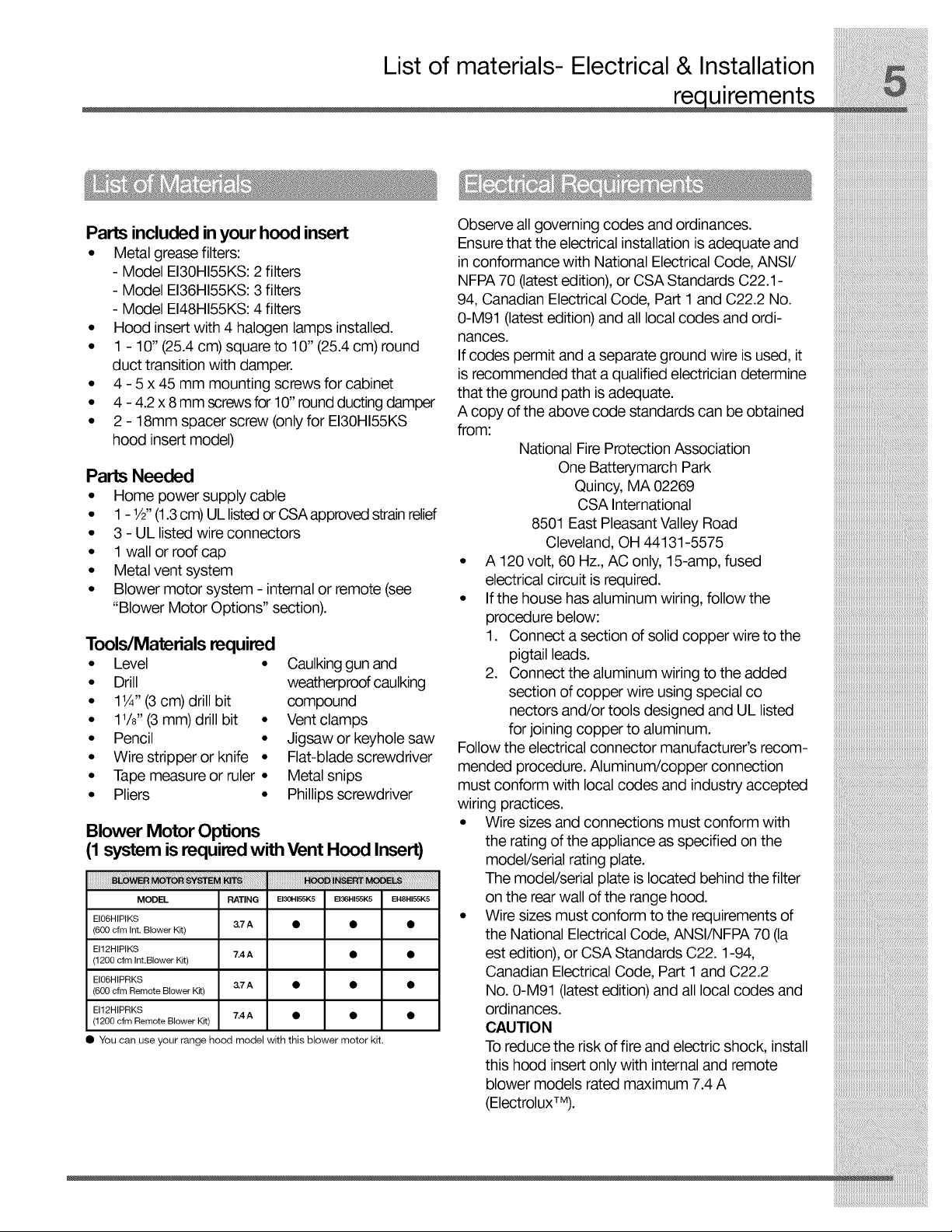
Blower Motor Options
(1 system is required with Vent Hood Insert)
iiiiiiiiiiiiiiiiiiiiiiiiiiiiiiiiiiiiiii i i i i i i i i i iiiiiiiiiiiiiiiiiiiiiiiii i i i i iI
MODEL RATING EI30HI55K5 EI36HI55K5 EI48HI55K5
EI06HIPIKS
(600 cfm Int. Blower Kit)
El12HIPIKS
(1200 cfm Int.Blewer Kit)
EI06HIPRKS
(600 cfm Remote Blower Kit)
EI12HIPRKS
(1200 cfm Remote Blower Kit)
• You can use your range hood model with this blower motor kit.
&7A • • •
7.4A • •
&7A • • •
7.4A • • •
Observe all governing codes and ordinances.
Ensure that the electrical installation is adequate and
in conformance with National Electrical Code, ANSI/
NFPA 70 (latest edition), or CSA Standards C22.1 -
94, Canadian Electrical Code, Part 1 and C22.2 No.
0-M91 (latest edition) and all local codes and ordi-
nances.
If codes permit and a separate ground wire is used, it
is recommended that a qualified electrician determine
that the ground path is adequate.
A copy of the above code standards can be obtained
from:
National FireProtection Association
One Batterymarch Park
Quincy, MA 02269
CSA International
8501 East Pleasant Valley Road
Cleveland, OH 44131-5575
• A 120 volt, 60 Hz., AC only, 15-amp, fused
electrical circuit is required.
• If the house has aluminum wiring, followthe
procedure below:
1. Connect a section of solid copper wire to the
pigtail leads.
2. Connect the aluminum wiring to the added
section of copper wire using special co
nectors and/or tools designed and UL listed
for joining copper to aluminum.
Follow the electrical connector manufacturer's recom-
mended procedure. Aluminum/copper connection
must conform with local codes and industry accepted
wiring practices.
• Wire sizes and connections must conform with
the rating of the appliance as specified on the
model/serial rating plate.
The model/serial plate is located behind the filter
on the rear wall of the range hood.
• Wire sizes must conform to the requirements of
the National Electrical Code, ANSl/NFPA 70 (la
est edition), or CSA Standards C22. 1-94,
Canadian Electrical Code, Part 1and C22.2
No. 0-M91 (latest edition) and all local codes and
ordinances.
CAUTION
Toreduce the risk of fire and electric shock, install
this hood insert only with internal and remote
blower models rated maximum 7.4 A
(ElectroluxTM).
Location requirements
IMPORTANT."Observe all governing codes and ordi-
nances. Have a qualified technician install the hood
insert. It is the installer's responsibility to comply with
installation clearances specified on the model/serial
rating plate. The model/serial rating plate is located
behind the left filter on the rear wall of the hood
insert.
The hood insert location should be away from strong
draft areas, such as windows, doors and strong heat-
ing vents.
Cabinet opening dimensions that are shown must be
used. Given dimensions provide minimum clearance.
The hood insert must be surrounded by a custom built
enclosure with hood cabinet capable of supporting 75
Ib (34kg).
Grounded electrical outlet is required. See "Electrical
Requirements" section on page 5.
All openings inceiling and wall where canopy hood
will be installed must be sealed.
For Mobile Home Installations
The installation of this hood insert must conform to the
Manufactured Home Construction Safety Standards,
Title 24 CFR, Part 328 (formerly the Federal Standard
for Mobile Home Construction and Safety, Title 24,
HUD, Part 280) or when such standard is not appli-
cable, the standard for Manufactured Home
Installation 1982 (Manufactured Home Sites, Commu-
nities and Setups) ANSI A225.1/NFPA 501A, or latest
edition, or with local codes.
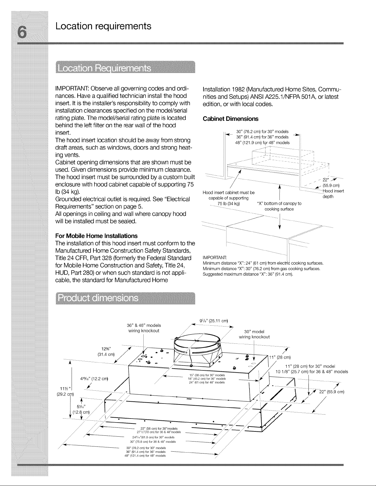
Cabinet Dimensions
30" (76.2 cm) for 30" models
_- 36" (91.4 cm) for 36" models -_'_::
I 48" (121.9 cm) fqr 48" models
Hood insert cabinet must be | CI Hood insert
capable of supporting | depth
75 Ib (34 kg) "X" bottom of canopy to
cooking surface
IMPORTANT: i
Minimum distance "X": 24" (61 cm) from electric cooking surfaces.
Minimum distance "X": 30" (76.2 cm) from gas cooking surfaces.
Suggested maximum distance "X": 36" (91.4 cm).
12%"
(31.4 cm)
36" & 48" models
wiring knockout
22" (56 cm) for 30"models
27V2"(70 cm) for 36 & 48"models
24_/_6"(61.8 cm) for 30" models
30" (75.8 cm) for 36 & 48" models
30" (76,2 cm) for 30" models
36" (91.4 cm) for 36" models __
48" (121,4 cm) for 48" models
97/8'' (25.11 cm)
15" (38 cm) for 30" models
18" (45.2 cm) for 36" models
24" (61 cm) for 48" models
30" model
wiring knockout
&
I
11" (28 cm)
11" (28 cm) for 30" model
10 1/8" (25.7 cm) for 36 & 48" models
/(55.9 cm)
Venting Requirements
° Vent system must terminate to the outdoors.
• Do not terminate the vent system in an attic or
other enclosed area.
° Do not use 4" (10.2 cm) laundry-type wall caps.
° Use metal vent only. Rigid metal vent is
recommended. Plastic or metal foil vent is not
recommended.
° The length of vent system and number of elbows
should be kept to a minimum to provide efficient
performance.
For the most efficient and quiet operation:
• Use no more than three 90° elbows.
• Make sure there is a minimum of 24" (61.0 cm) of
straight vent between the elbows if more than 1
elbow is used.
• Do not install 2 elbows together.
• Use clamps to seal all joints inthe vent system
and use furnace duct tape to fully seal joint
connection.
• Use caulking to seal exterior wall or roof opening
around the cap.
On installations using the 1200 CFM Blower Motor
Systems, a 10" round vent system should be
used.
You can use a smaller round vent system, but
there will be a louder sound level.
NOTE: Flexible vent is not recommended.
Flexible vent creates back pressure and air
turbulence that greatly reduce performance.
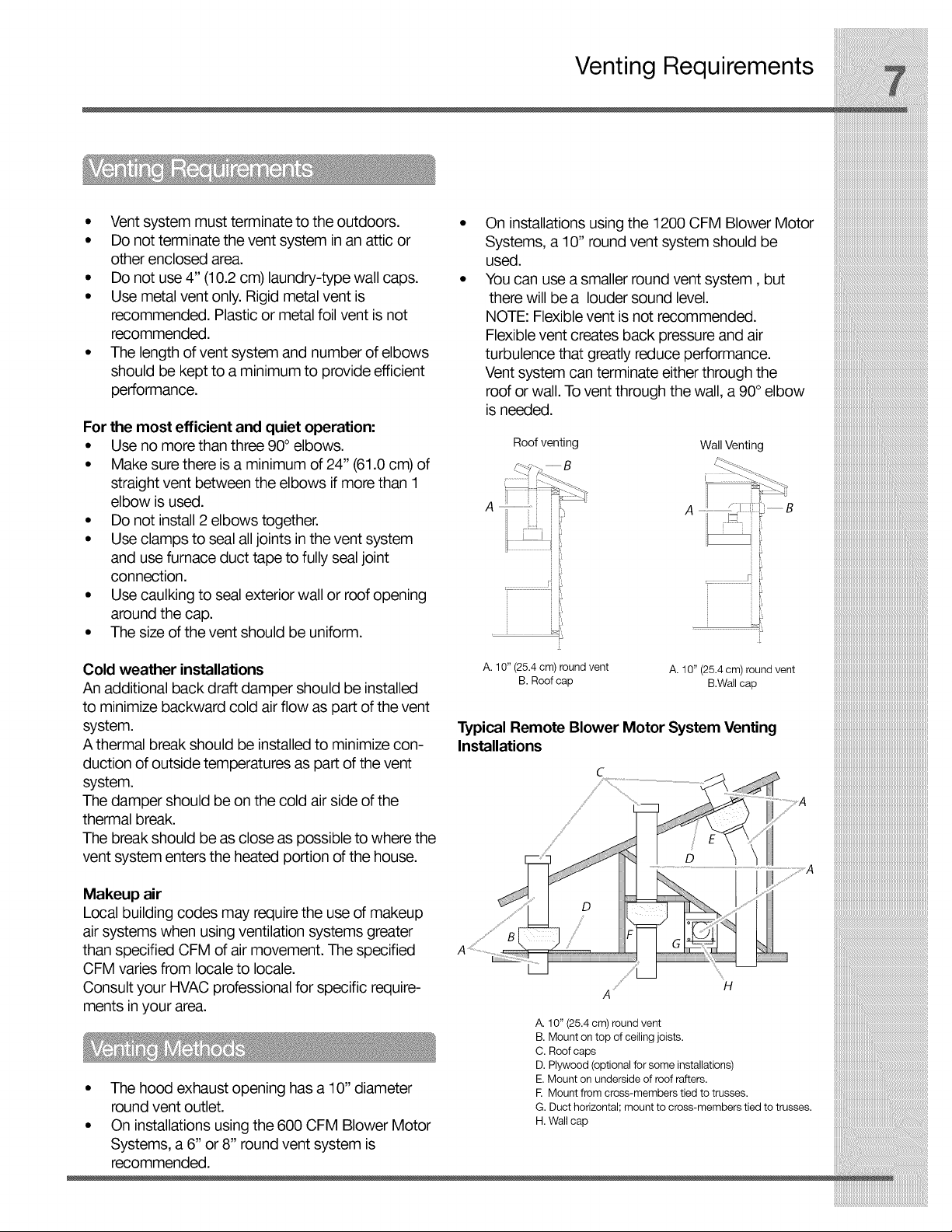
Vent system can terminate either through the
roof or wall. To vent through the wall, a 90°elbow
is needed.
Roof venting Wall Venting
_---_j--j_.....................B "__-
........................................_[ _,_ B
_ _ i'!',
i !!!!!!!!!iii:Blower Motor Systems Installation
_______________________________________________________________________________________________________________________________________________________________4. Installthe6 mm clip nutstotheoutsidetop
_i_i_i_i_i_i_i_i_i_i_i_i_i_i_i_i_i_i_i_i_i_i_i_i_i_i_i_i_i_i_i_i_i_i_i_i_i_i_i_i_i_i_i_i_i_i_i_i_i_i_i_i_i_i_i_i_i_i_i_i_i_i_i_i_i_i_i_i_i_i_i_i_i_i_i_i_i_i_iI ofthehoodinsertattheproperlocationforthe
_lllllllllllllllllllllllllllllllllllllllllllllllllllllllllllllllllllllllllllllll
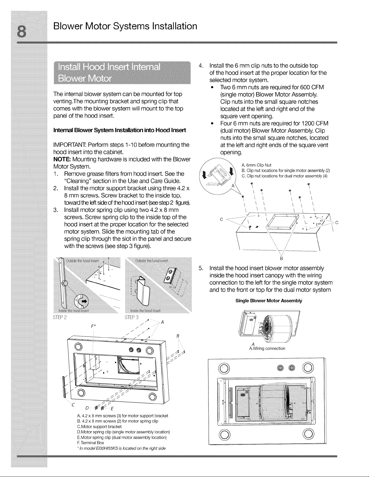
The internal blower system can be mounted for top
venting.The mounting bracket and spring clip that
comes with the blower system will mount to the top
panel of the hood insert.
InternalBlower SystemInstallationinto Hood Insert
IMPORTANT."Perform steps 1-10 before mounting the
hood insert into the cabinet.
NOTE: Mounting hardware is included with the Blower
Motor System.
1. Remove grease filters from hood insert. See the
"Cleaning" section in the Use and Care Guide.
2. Installthe motor support bracket using three 4.2 x
8 mm screws. Screw bracket to the inside top,
towardthe leftsideofthehood insert(seestep2 figure).
3. Install motor spring clip using two 4.2 x 8 mm
screws. Screw spring clip to the inside top of the
hood insert at the proper location for the selected
motor system. Slide the mounting tab of the
spring clip through the slot in the panel and secure
with the screws (seestep 3 figure).
selected motor system.
• Two 6 mm nuts are required for 600 CFM
(single motor) Blower Motor Assembly.
Clip nuts into the small square notches
located at the left and right end of the
square vent opening.
• Four 6 mm nuts are required for 1200 CFM
(dual motor) Blower Motor Assembly. Clip
nuts into the small square notches, located
at the left and right ends of the square vent
opening.
A. 6mm Clip Nut
B. Clip nut locations for single motor assembly (2)
C. Clip nut locations for dual motor assembly (4)
\ \ \
\ o
:l .......
iiiiiiiiiiiiiiiiiiiii
A. 4.2 x 8 mm screws (3) for motor support bracket
B. 4.2 x 8 mm screws (2)for motor spring clip
C.Motor support bracket
D.Motor spring clip (single motor assembly location)
E.Motor spring clip (dual motor assembly location)
ETerminal Box
* Inmodel EI30HI55KS is located on the #ght side
.
Installthe hood insert blower motor assembly
inside the hood insert canopy with the wiring
connection to the left for the single motor system
and to the front or top for the dual motor system
Single Blower Motor Assembly
B
A
A.Wiring connection
© ©
Blower Motor Systems Installation
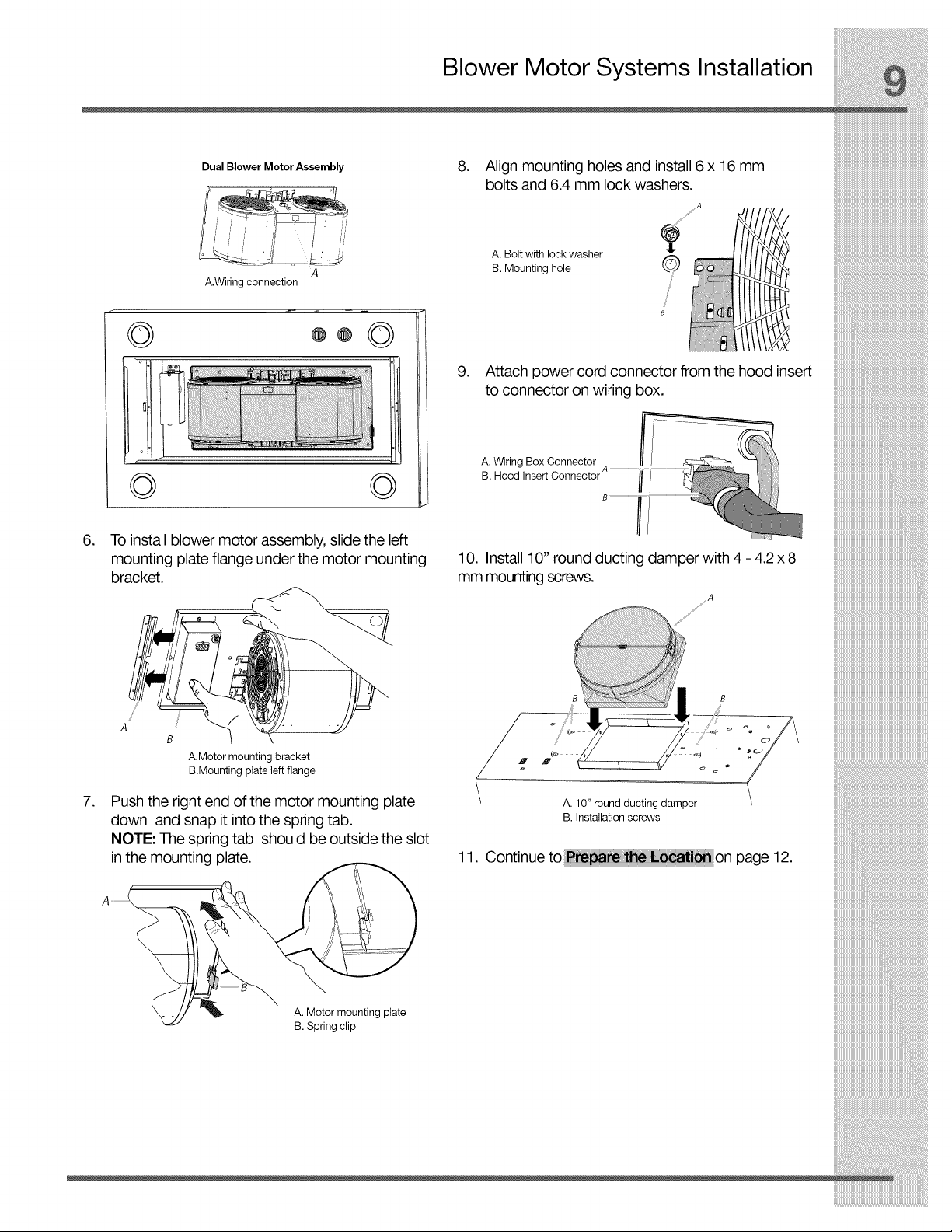
Dual Blower Motor Assembly
A.Wiringconnection
A
6. To install blower motor assembly, slide the left
mounting plate flange under the motor mounting
bracket.
8. Align mounting holes and install 6 x 16 mm
bolts and 6.4 mm lock washers.
A. Bolt with lock washer
B. Mounting hole
.I.
©
8
9. Attach power cord connector from the hood insert
to connector on wiring box.
10. Install 10" round ducting damper with 4 - 4.2x8
mm mounting screws.
A
A.Motor mounting bracket
B.Mounting plate left flange
.
Push the right end of the motor mounting plate
down and snap it into the spring tab.
NOTE: The spring tab should be outside the slot
in the mounting plate.
A. Motor mounting plate
B. Spring clip
B B
A. 10" round ducting damper
B. Installation screws
11. Continueto __ ti_on page 12.
Blower Motor Systems Installation
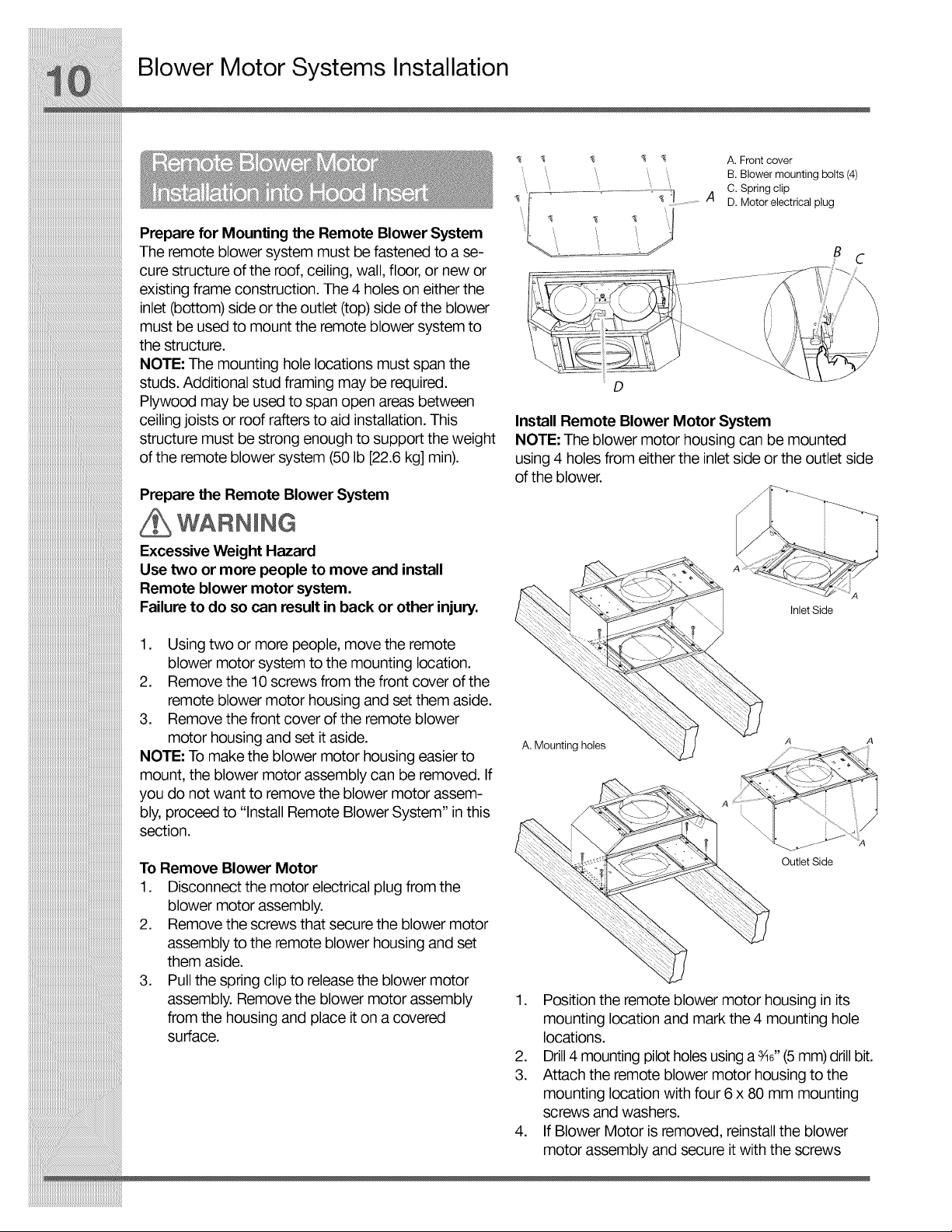
fi ! A. Front cover
",,, ", B. Blower mounting bolts (4)
" C. Spring clip
A D. Motor electrical plug
_iiiiiiiiiiiiiiiiiiiiiiiiiiiiiiiiiiiiiiiiiiiiiiiiiiiiiiiiiiiiiiiiiiiiiiiiiiiiiii
Prepare for Mounting the Remote Blower System
The remote blower system must be fastened to a se-
cure structure of the roof, ceiling, wall, floor, or new or
existing frame construction. The 4 holes on either the
inlet (bottom) side or the outlet (top) side of the blower
must be used to mount the remote blower system to
the structure.
NOTE: The mounting hole locations must span the
studs. Additional stud framing may be required.
Plywood may be used to span open areas between
ceiling joists or roof rafters to aid installation. This
structure must be strong enough to support the weight
of the remote blower system (50 Ib [22.6 kg] min).
Prepare the Remote Blower System
WARNING
Excessive Weight Hazard
Use two or more people to move and install
Remote blower motor system.
Failure to do so can result in back or other injury.
1. Using two or more people, move the remote
blower motor system to the mounting location.
2. Remove the 10 screws from the front cover of the
remote blower motor housing and set them aside.
3. Remove the front cover of the remote blower
motor housing and set itaside.
NOTE: To make the blower motor housing easier to
mount, the blower motor assembly can be removed. If
you do not want to remove the blower motor assem-
bly, proceed to "Install Remote Blower System" in this
section.
B
s d"
D
Install Remote Blower Motor System
NOTE: The blower motor housing can be mounted
using 4 holes from either the inlet side or the outlet side
of the blower.
Inlet Side
A. Mounting holes
To Remove Blower Motor
1. Disconnect the motor electrical plug from the
blower motor assembly.
2. Remove the screws that secure the blower motor
assembly to the remote blower housing and set
them aside.
3. Pull the spring clip to releasethe blower motor
assembly. Remove the blower motor assembly
from the housing and place iton a covered
surface.
Outlet Side
1. Position the remote blower motor housing in its
mounting location and mark the 4 mounting hole
locations.
2. Drill 4 mounting pilot holes using a _6" (5mm) drillbit.
3. Attach the remote blower motor housing to the
mounting location with four 6 x 80 mm mounting
screws and washers.
4. If Blower Motor is removed, reinstall the blower
motor assembly and secure it with the screws
Blower Motor Systems Installation
previously removed. If it is removed, reattach the
motor electrical plug to the connector on the
blower motor assembly.
Complete Preparation
1. Determine and make all necessary cuts for the
vent system.
IMPORTANT: When cutting or drilling into the ceiling
or wall, do not damage electrical wiring or other hid-
den utilities.
2. Determine the location where the 1/2"(1.3cm)
wiring conduit will be routed through the ceiling or
wall between the remote blower and the hood insert.
3• Drilla 1W' (3.2 cm) hole at this location.
4. Locate the electrical terminal boxes in the remote
blower housing and hood insert (see "Complete
Preparation" in the "Prepare Location" section).
Remove the terminal box covers and set the
covers and screws aside.
• ' _ Motor System
° WARNING
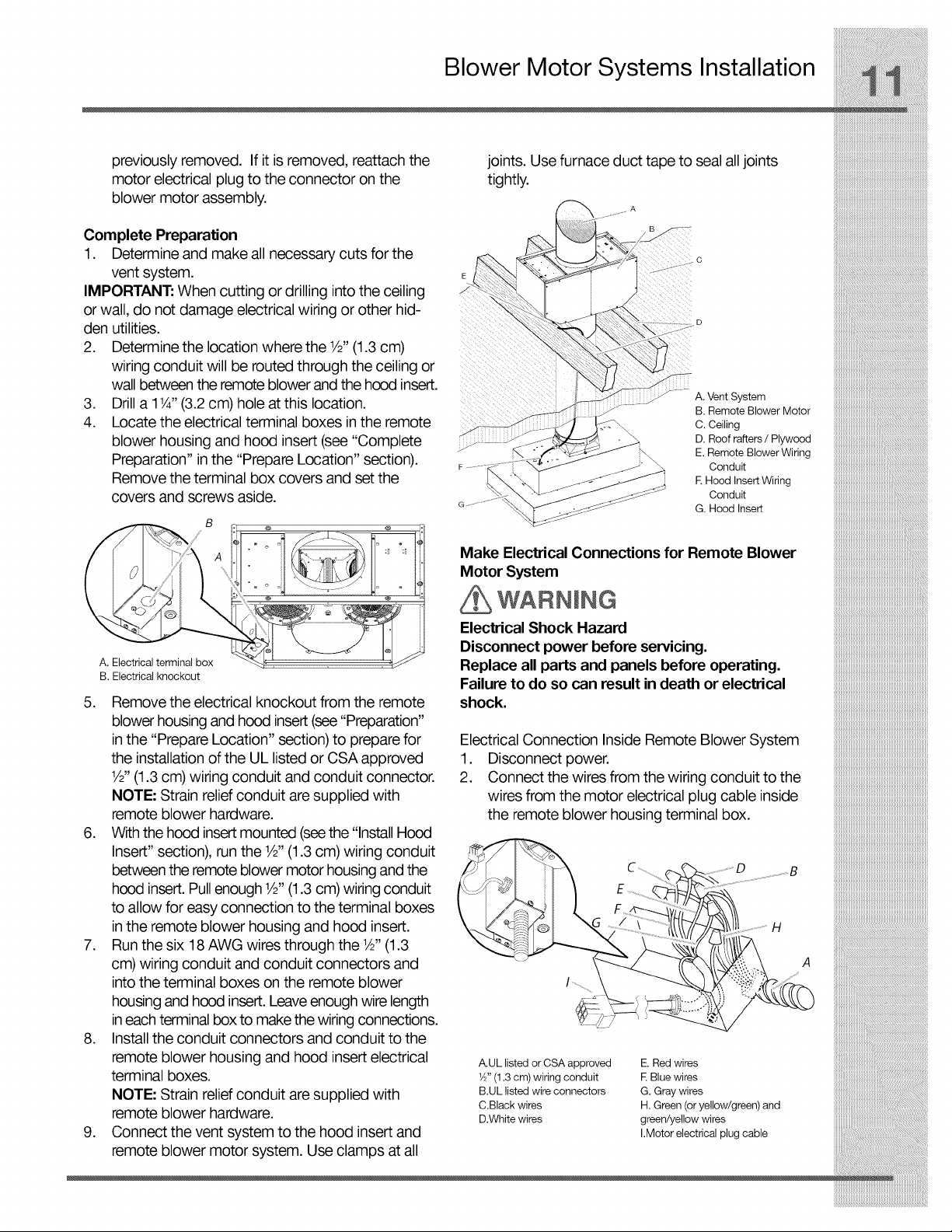
joints. Use furnace duct tape to seal alljoints
tightly.
A. Vent System
B. Remote Blower Motor
C. Ceiling
D. Roof rafters / Plywood
E. Remote Blower Wiring
Conduit
i E Hood Insert Wiring
Conduit
G. Hood Insert
Electrical Shock Hazard
Make Electrical Connections for Remote Blower
Disconnect power before servicing.
A. Electrical terminal box Replace all parts and panels before operating.
B. Electrical knockout Failure to do so can result in death or electrical
5. Remove the electrical knockout from the remote shock.
blower housing and hood insert (see "Preparation"
in the "Prepare Location" section) to prepare for Electrical Connection Inside Remote Blower System
the installation of the UL listed or CSA approved 1. Disconnect power•
1 " ........
V2 (1.3cm) wmng conduit and conduit connector. 2. Connect the wires from the wmng conduit to the
NOTE: Strain reliefconduit are supplied with wires from the motor electrical plug cable inside
remote blower hardware. ,, the remote blower housing terminal box.
6. Withthe hood insert mounted (seethe Install Hood
" ' 1 " '' ' _ '_._,.._
Insert section), run the V2 (1 3 cm) wlnn conduit
. g
between the remote blower motor housing andthe _ _ _F'Xk C D
hood insert.Pull enough1/2"(1•3cm) wiring conduit i{_ ,X-_L ii / E...........__ ..................................
to allow for easy connection to the terminal boxes , /_:\"_ I /_ F ,P_ y_(/_2//2//_'_
n the remote bower hobs ng and hood nsert \_ _ _ I _G ......................................................,_//f_;__i_/_7!'_'_\il....................H
/ .................o, j
G / \ _\lli
7. Run the six 18 AWG wires through the 1/_ (1.3 /L._._[I/_
cm) w r ng condu t and condu t connectors and _ :_" __:::.._ A
into the terminal boxes on the remote blower __i_i_((2P-,
housingand hood insert. Leave enough wire length __, __
ineach terminal box to make the wiring connections.
8. Install the conduit connectors and conduit to the
remote blower housing and hood insert electrical A.UL listed or CSA approved E.Red wires
terminal boxes. _" (1.3 cm)wiring conduit E Blue wires
N TE" tr in r li f n it r li with BUL stedwreconnectors G Graywres
O .S a ee co du aesupped • . • , , , .
..... C.BlacK wires H. Green [or yellow/green) ana
remote plower naraware. U.White wires green/yellow wires
9. Connect the vent system to the hood insert and I.Motorelectricalplugcable
remote blower motor system. Use clamps at all
Make Electrical Connections
3. Use UL listed wire connectors and connect the to black, white to white, etc.) using UL listed wire
black wires (C)together.
Use UL listed wire connectors and connect the
white wires (D)together.
Use UL listed wire connectors and connect the
red wires (E)together.
Use UL listed wire connectors and connect the
blue wires (F)together.
.
Use UL listed wire connectors and connect the
gray wires (G)together.
connectors.
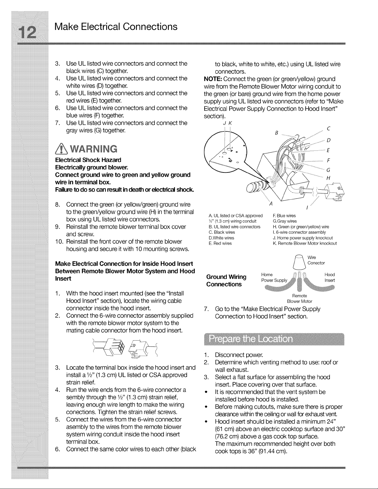
NOTE."Connect the green (or green/yellow) ground
wire from the Remote Blower Motor wiring conduit to
the green (or bare)ground wire from the home power
supply using UL listed wire connectors (referto "Make
Electrical Power Supply Connection to Hood Insert"
section).
JK
B _f _S_
c
D
WARNING
Electrical Shock Hazard
Electrically ground blower.
Connect ground wire to green and yellow ground
wire in terminal box.
Failureto do so canresult indeath orelectrical shock.
8. Connect the green (or yellow/green) ground wire
to the green/yellow ground wire (H)in the terminal
box using UL listed wire connectors.
9. Reinstall the remote blower terminal box cover
and screw.
10. Reinstall the front cover of the remote blower
housing and secure it with 10 mounting screws.
A. UL listed or CSA approved
W' (1.3 cm) wiring conduit
B. UL listed wire connectors
C. Black wires
D.White wires
E. Red wires
%
A iy
E Blue wires
G.Gray wires
H.Green(orgreen/yellow)wire
I. 6-wire connector assembly
J. Home power supply knockout
K. Remote Blower Motor knockout
/
G
H
Make Electrical Connection for Inside Hood Insert
Between Remote Blower Motor System and Hood
Insert
1. With the hood insert mounted (seethe "Install
Hood Insert" section), locate the wiring cable
connector inside the hood insert.
2. Connect the 6-wire connector assembly supplied
with the remote blower motor system to the
mating cable connector from the hood insert.
3. Locate the terminal box inside the hood insert and
install a 1/=,(1.3 cm) UL listed or CSA approved
strain relief.
4. Run the wire ends from the 6-wire connector a
sembly through the 1/=,(1.3cm) strain relief,
leaving enough wire length to make the wiring
conections. Tighten the strain relief screws.
5. Connect the wires from the 6-wire connector
asembly to the wires from the remote blower
system wiring conduit inside the hood insert
terminal box.
6. Connect the same color wires to each other (black
Conector
Wire
Ground Wiring
Connections
Remote
Blower Motor
.
Go to the "Make Electrical Power Supply
Connection to Hood Insert" section.
1. Disconnect power.
2. Determine which venting method to use: roof or
wall exhaust.
3. Select a flat surface for assembling the hood
insert. Place covering over that surface.
• It is recommended that the vent system be
installed before hood is installed.
• Before making cutouts, make sure there is proper
clearancewithin theceilingor wall for exhaustvent.
• Hood insert should be installed a minimum 24"
(61 cm) above an electric cooktop surface and 30"
(76.2 cm) above a gas cook top surface.
The maximum recommended height over both
cook tops is 36" (91.44 cm).
Make Electrical Connections
• Check that all installation parts have been
removed from the shipping carton.
4. Using 2 or more people, lift hood insert onto
covered surface.
5. Remove the filters. See the "Cleaning"
section on page 15.
The hood insert attaches to the hood cabinet using
four mounting screws and washers.
NOTE: Hood cabinet must be capable of supporting
75 Ib (34 kg).
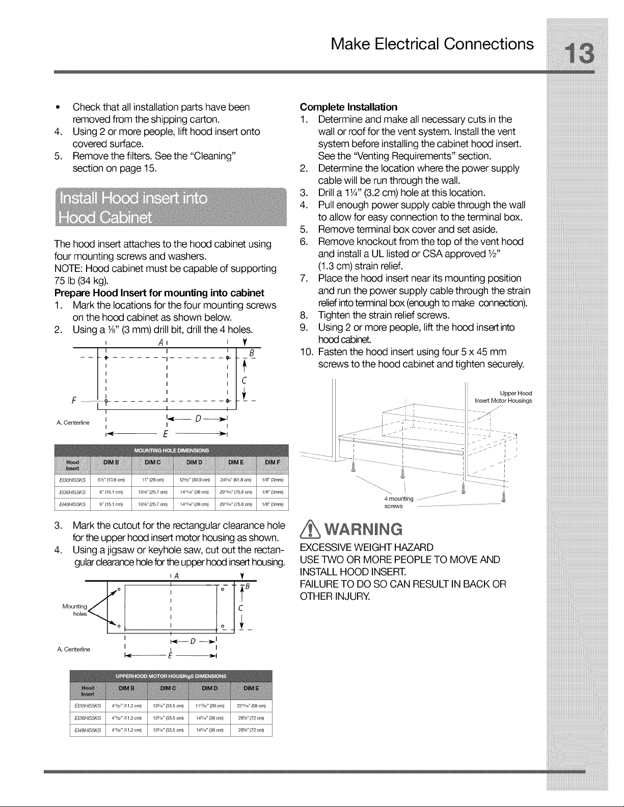
Prepare Hood Insert for mounting into cabinet
1. Mark the locations for the four mounting screws
on the hood cabinet as shown below.
2. Using a W' (3 mm)drill bit, drill the 4 holes.
I
F ..................i,_
A. Centerline I
I
I
A t
.4 e-
l
Lqr_-_ D _t
I t
t
e-
l
I
I
I
Complete Installation
1. Determine and make all necessary cuts in the
wall or roof for the vent system. Install the vent
system before installing the cabinet hood insert.
See the "Venting Requirements" section.
2. Determine the location where the power supply
cable will be run through the wall.
3. Drill a 118"(3.2cm) hole at this location.
4. Pull enough power supply cable through the wall
to allow for easy connection to the terminal box.
5. Remove terminal box cover and set aside.
6. Remove knockout from the top of the vent hood
and install a UL listed or CSA approved W'
(1.3 cm) strain relief.
7. Place the hood insert near its mounting position
and run the power supply cable through the strain
reliefinto terminal box (enoughto make connection).
8. Tighten the strain relief screws.
9. Using 2 or more people, lift the hood insert into
hood cabinet.
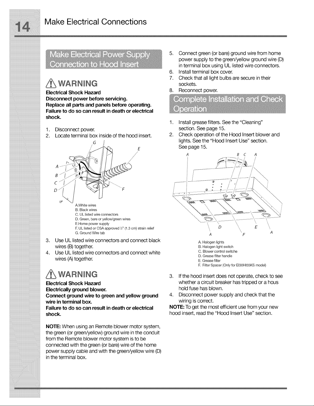
10. Fasten the hood insert using four 5 x 45 mm
screws to the hood cabinet and tighten securely.
Upper Hood
Insert Motor Housings
24586 " (61.8 cm)
29_°86 "(75.8 cm)
29_°86 "(75.8 cm)
3. Mark the cutout for the rectangular clearance hole
forthe upper hood insert motor housing as shown.
4. Using a jigsaw or keyhole saw, cut out the rectan-
gularclearanceholefortheupper hoodinserthousing.
IA y
Mounting_ L_°
holes'_ o
A. Centerline
I
I
4 la/32" (1 1.2 cm)
4_3/32" (1 1.2 cm)
4_3/32" (1 1.2 cm)
n C
I -] B
I _ _
I
I I
E _I
4 mounting .............................
screws ..................................................................................
EXCESSIVE WEIGHT HAZARD
USE TWO OR MORE PEOPLE TO MOVE AND
INSTALL HOOD INSERT.
FAILURE TO DO SO CAN RESULT IN BACK OR
OTHER INJURY.
Make Electrical Connections
WARNING
Electrical Shock Hazard
Disconnect power before servicing.
Replace all parts and panels before operating.
Failure to do so can result indeath or electrical
shock.
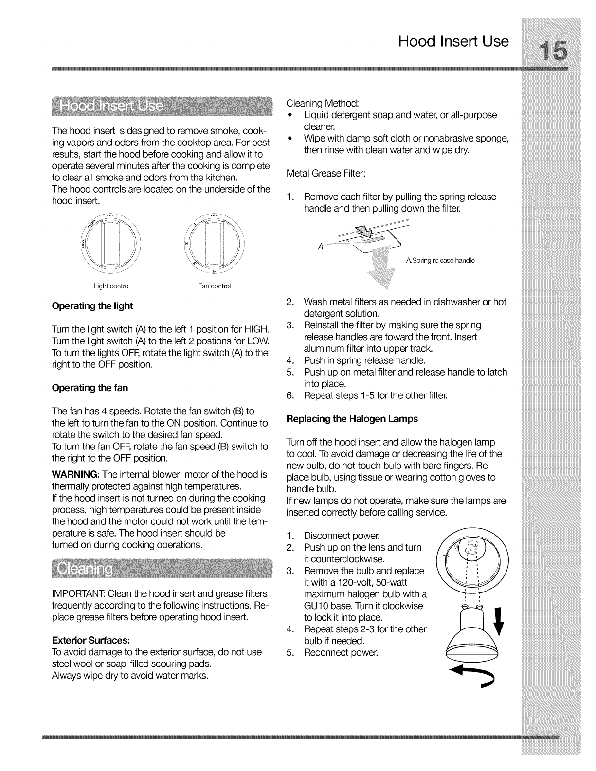
.
Disconnect power.
2.
Locate terminal box insideof the hood insert.
G
E
A
B
C
D
5. Connect green (or bare)ground wire from home
power supply to the green/yellow ground wire (D)
in terminal box using UL listed wire connectors.
6. Install terminal box cover.
7. Check that all light bulbs are secure in their
sockets.
8. Reconnect power.
.
Install grease filters. See the "Cleaning"
section. See page 15.
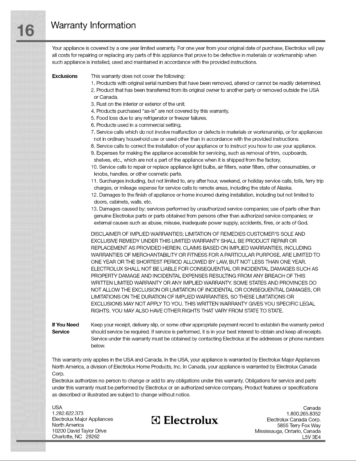
2.
Check operation of the Hood Insert blower and
lights. See the "Hood Insert Use" section.
See page 15.
A B C A
A.White wires
B. Black wires
C. UL listed wire connectors
D. Green, bare or yellow/green wires
E.Home power supply
R UL listed or CSA approved ½" (1.3 cm) strain relief
G. Ground Wire tab
.
Use UL listed wire connectors and connect black
wires (B)together.
4.
Use UL listed wire connectors and connect white
wires (A)together.
WARNING
Electrical Shock Hazard
Electrically ground blower.
Connect ground wire to green and yellow ground
wire in terminal box.
Failure to do so can result in death or electrical
shock.
NOTE: When using an Remote blower motor system,
the green (or green/yellow) ground wire in the conduit
from the Remote blower motor system is to be
connected with the green (or bare) wire of the home
power supply cable and with the green/yellow wire (D)
in the terminal box.
A F
A. Halogen lights
B. Halogen light switch
C. Blower control switche
D. Grease filter handle
E. Grease filter
E Filter Spacer (Only for EI30HI55KS model)
3. If the hood insert does not operate, check to see
whether a circuit breaker has tripped or a hous
hold fuse has blown.
4. Disconnect power supply and check that the
wiring is correct.
NOTE: To get the most efficient use from your new
hood insert, read the "Hood Insert Use" section.
The hood insert is designed to remove smoke cook-
ing vapors and odors from the cooktop area. For best
results, start the hood before cooking and allow it to
operate several minutes after the cooking is complete
to clear all smoke and odors from the kitchen.
The hood controls are located on the underside of the
hood insert.
Light control Fan control
Operating the light
Turnthe light switch (A)to the left 1 position for HIGH.
Turnthe light switch (A)to the left 2 postions for LOW.
Toturn the lights OFF,rotate the light switch (A)to the
right to the OFF position.
Operating the fan
The fan has 4 speeds. Rotate the fan switch (B)to
the left to turn the fan to the ON position. Continue to
rotate the switch to the desired fan speed.
Toturn the fan OFF, rotate the fan speed (B) switch to
the right to the OFF position.
WARNING: The internal blower motor of the hood is
thermally protected against high temperatures.
If the hood insert is not turned on during the cooking
process, high temperatures could be present inside
the hood and the motor could not work until the tem-
perature is safe. The hood insert should be
turned on during cooking operations.
IMPORTANT."Clean the hood insert and grease filters
frequently according to the following instructions. Re-
place grease filters before operating hood insert.
Exterior Surfaces'.
Toavoid damage to the exterior surface, do not use
steel wool or soap-filled scouring pads.
Always wipe dry to avoid water marks.
Hood Insert Use
Cleaning Method:
° Liquid detergent soap and water, or all-purpose
cleaner.
° Wipe with damp soft cloth or nonabrasive sponge,
then rinse with clean water and wipe dry.
Metal Grease Filter:
1. Remove each filter by pulling the spring release
handle and then pulling down the filter.
A.Spring release handle
2. Wash metal filters as needed in dishwasher or hot
detergent solution.
3. Reinstall the filter by making sure the spring
release handles are toward the front. Insert
aluminum filter into upper track.
4. Push in spring release handle.
5. Push up on metal filter and release handle to latch
into place.
6. Repeat steps 1-5 for the other filter.
Replacing the Halogen Lamps
Turnoff the hood insert and allow the halogen lamp
to cool. To avoid damage or decreasing the lifeof the
new bulb, do not touch bulb with bare fingers. Re-
place bulb, using tissue or wearing cotton gloves to
handle bulb.
If new lamps do not operate, make sure the lamps are
inserted correctly before calling service.
1. Disconnect power, f__
2. Push up on the lens and turn
it counterclockwise.
3. Remove the bulb and replace
it with a 120-volt, 50-watt
maximum halogen bulb with a , ,
GU10 base. Turn itclockwise _ ..
to lock it into place.
4. Repeat steps 2-3 for the other
bulb if needed.
5. Reconnect power.
iiiiiiiiiiiiiiiiiiiiiiiiiiiiiiiiiiiiiiiiiiiiiiiiiiiiiiiiiiiiiiiiiiiiiiiiiiiiiii
Warranty Inform ation
Your appliance is covered by a one year limited warranty. For one year from your original date of purchase, Electrolux will pay
all costs for repairing or replacing any parts of this appliance that prove to be defective in materials or workmanship when
such appliance is installed, used and maintained in accordance with the provided instructions.
iiiiiiiiiiiiiiiiiiiiiiiiiiiiiiiiiiiiiiiiiiiiiiiiiiiiiiiiiiiiiiiiiiiiiiiiiiiiiii
Exclusions
This warranty does not cover the following:
1. Products with original serial numbers that have been removed, altered or cannot be readily determined.
2. Product that has been transferred from its original owner to another party or removed outside the USA
or Canada.
3. Rust on the interior or exterior of the unit.
4. Products purchased "as-is" are not covered by this warranty.
5. Food loss due to any refrigerator or freezer failures.
6. Products used ina commercial setting.
7. Service calls which do not involve malfunction ordefects inmaterials or workmanship, or for appliances
not in ordinary household use or used other than in accordance with the provided instructions.
8. Service calls to correct the installation of your appliance or to instruct you how to use your appliance.
9. Expenses for making the appliance accessible for servicing, such as removal of trim, cupboards,
shelves, etc., which are not a part of the appliance when it is shipped from the factory.
10. Service calls to repair or replace appliance light bulbs, air filters, water filters, other consumables, or
knobs, handles, or other cosmetic parts.
11. Surcharges including, but not limited to, any after hour, weekend, or holiday service calls, tolls, ferry trip
charges, or mileage expense for service calls to remote areas, including the state of Alaska.
12. Damages to the finish of appliance or home incurred during installation, including but not limited to
doors, cabinets, walls, etc.
13. Damages caused by: services performed by unauthorized service companies; use of parts other than
genuine Electrolux parts or parts obtained from persons other than authorized service companies; or
external causes such as abuse, misuse, inadequate power supply, accidents, fires, or acts of God.
DISCLAIMER OF IMPLIED WARRANTIES; LIMITATION OF REMEDIES CUSTOMER'S SOLE AND
EXCLUSIVE REMEDY UNDER THIS LIMITED WARRANTY SHALL BE PRODUCT REPAIROR
REPLACEMENT AS PROVIDED HEREIN. CLAIMS BASED ON IMPLIED WARRANTIES, INCLUDING
WARRANTIES OF MERCHANTABILITY OR FITNESS FOR A PARTICULAR PURPOSE, ARE LIMITED TO
ONE YEAR OR THE SHORTEST PERIODALLOWED BY LAW, BUT NOT LESS THAN ONE YEAR.
ELECTROLUX SHALL NOT BE LIABLE FOR CONSEQUENTIAL OR INCIDENTAL DAMAGES SUCH AS
PROPERTY DAMAGE AND INCIDENTAL EXPENSES RESULTING FROM ANY BREACH OF THIS
WRI-I-I-ENLIMITED WARRANTY OR ANY IMPLIED WARRANT_. SOME STATESAND PROVINCES DO
NOT ALLOW THE EXCLUSION OR LIMITATION OF INCIDENTAL OR CONSEQUENTIAL DAMAGES, OR
LIMITATIONS ON THE DURATION OF IMPLIED WARRANTIES, SO THESE LIMITATIONSOR
EXCLUSIONS MAY NOT APPLYTO YOU. THIS WRI-I-I-ENWARRANTY GIVES YOU SPECIFIC LEGAL
RIGHTS. YOU MAY ALSO HAVE OTHER RIGHTS THAT VARY FROM STATETO STATE.
IfYou Need
Service
This warranty only applies in the USA and Canada. In the USA, your appliance is warranted by Electrolux Major Appliances
North America, a division of Electrolux Home Products, Inc. In Canada, your appliance is warranted by Electrolux Canada
Corp.
Electrolux authorizes no person to change or add to any obligations under this warranty. Obligations for service and parts
under this warranty must be performed by Electrolux or an authorized service company. Product features or specifications
as described or illustrated are subject to change without notice.
USA
1.282.622.373
Electrolux Major Appliances
North America
10200 David Taylor Drive
Charlotte, NC 28262
Keep your receipt, delivery slip, or some other appropriate payment record to establish the warranty period
should service be required. Ifservice is performed, it isin your best interest to obtain and keep all receipts.
Service under this warranty must be obtained by contacting Electrolux at the addresses or phone numbers
below.
Canada
1.800.265.8352
Electrolux
Electrolux Canada Corp.
5855 Terry Fox Way
Mississauga, Ontario, Canada
L5V 3E4
 Loading...