

Electrolux EI30GS55JSB, EI30GS55JSC, EI30GS55LBA, EI30GS55LBB, EI30GS55LWA Installation Guide
...
iNSTALLATION AND SERVICE MUST BE PERFORMED BY A QUALiFiED INSTALLER.
iMPORTANT: SAVE FOR LOCAL ELECTRICALINSPECTOR'S USE.
READ AND SAVE THESE iNSTRUCTiONS FOR FUTURE REFERENCE.
If the information in this manual is not followed exactly, a fire
or explosion may result causing property damage, personal injury or death.
FOR YOUR SAFETY:
--Do not store or use gasoline or other flammable vapors and liquids in the
vicinity of this or any other appliance.
--WHAT TO DO IF YOU SMELL GAS:
• Do not try to light any appliance.
• Do not touch any electrical switch; do not use any phone in your building.
• Immediately call your gas supplier from a neighbor's phone. Follow the
gas supplier's instructions.
• If you cannot reach your gas supplier, call the fire department.
--Installation and service must be performed by a qualified installer, service
agency or the gas supplier.
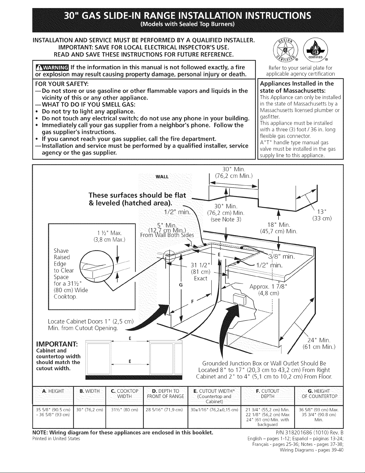
30" Min.
WALL (76,2 cm Min.)
These surfaces should be flat _,__
& leveled (hatched area). _ 30" M n _"
1/2" min._ (76 2 cm) IVIn """_"'_ / \ 13"
(see Note 3) _ (33 cm)
5" Min. _ 18" Min.
1 1/2"Max. Fro(l_a_r_o?4n_), \ _[ (45.... 7csides I _ m) Min.
Referto your serialplate for
applicableagencycertification
Appliances installed in the
state of Massachusetts:
ThisAppliancecan onlybe installed
in the stateof Massachusettsbya
Massachusettslicensedplumber or
gasfitter.
Thisappliancemust beinstalled
with athree (3)foot / 36 in. long
flexiblegasconnector.
A"T" handletype manualgas
valve mustbe installedin the gas
supplyline to thisappliance.
(3,8cm Max.)
Shave _ _,--
Raised / \ Ir _.._;,t--_ __3/8" min.
Edge __._t_ _i____ 31 1/2" - 1/2" _nin. _
to Clear _ ,_ J ' (81 cm) _ _-_.--_ i /'J
Space _ J' Exact i
for a 311/2'' _ e '_
(80 cm) Wide "_/
Cooktop. _ L _::::::.;_-_t',"-, ' -
_?_-Approx. 1 7/8"
• _:::::_. (4 8 cm)
./F "--<----4! i
Locate Cabinet Doors 1 (2 5 cm)
M . utout Open;'_g.'
iMPORTANT: _- W _.4_ -'---4 / (61 cm Min)
Cabinet and .. i _ _ _ | / "
countertop width
should match the _ E ,_i _ Grounded Junction Box or Wall Outlet Should Be
cutout width, ii i i Located 8" to 17" (20,3 cm to 43,2 cm) From Right
Cabinet and 2" to 4" (5,1 cm to 10,2 cm) From Floor.
A!H i WIDTH TOP DEPTHTO E. CUTOUT WIDTH * F; CUTOUT G. HEIGHT
EIGHT , C: CooK i
WIDTH FRONTOF RANGE (Countertop and DEPTH [ ©F COUNTERTOP
35 5/8" (90.5 cm) 30" (76,2 crn) 31Y2" (80 crn) 28 5/16" (71,9 cm) 30_+1/16" (76,2_+0,15cm) 21 3/4" (55,2 crn) Min. 36 5/8" (93 cm) Max.
- 36 5/8" (93 crn) 22 1/8" (56,2 crn) Max 35 3/4" (90.8 cm)
NOTE:Wiring diagram for these appliances are enclosed in this booklet.
Printed in United States
• Cabinet)
24" (61 crn) Min. with Min.
backguard
P/N 318201686 (1010) Rev. B
English - pages 1-12; Espaflol - p_iginas 13-24;
Fran_ais - pages 25-36; Notes - pages 37-38;
Wiring Diagrams - pages 39-40
" Min
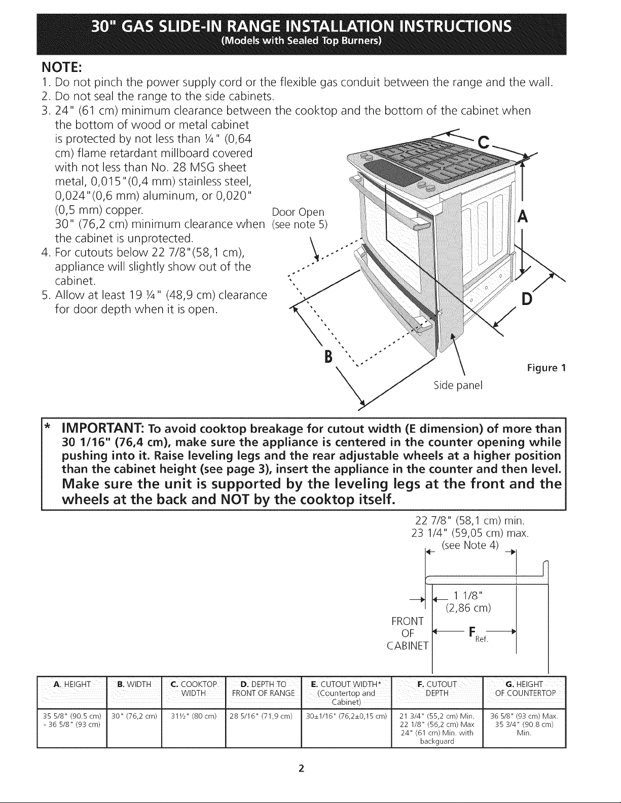
NOTE:
1. Do not pinch the power supply cord or the flexible gas conduit between the range and the wall.
2. Do not seal the range to the side cabinets.
3.24" (61 cm) minimum clearance between the cooktop and the bottom of the cabinet when
the bottom of wood or metal cabinet
is protected by not less than ¼" (0,64
cm) flame retardant miiiboard covered
with not less than No. 28 MSG sheet
metal, 0,015 "(0,4 mm) stainless steel,
0,024"(0,6 ram) aluminum, or 0,020"
(0,5 mm) copper. Door Open
30" (76,2 cm) minimum clearance when (see note 5)
the cabinet is unprotected. \ ,
4. For cutouts below 22 7/8"(58,1 cm), _ °"
oO
appliance will slightly show out of the ,,,-"
cabinet
5. Allow at least 19 ¼" (48,9 cm) clearance "
for door depth when it is open.
A
Side panel
_t
IMPORTANT: To avoid cooktop breakage for cutout width (E dimension) of more than
30 1/16" (76,4 cm), make sure the appliance is centered in the counter opening while
pushing into it. Raise leveling legs and the rear adjustable wheels at a higher position
than the cabinet height (see page 3), insert the appliance in the counter and then level.
Make sure the unit is supported by the leveling legs at the front and the
wheels at the back and NOT by the cooktop itself.
22 7/8" (58,1 cm) min.
23 1/4" (59,05 cm) max.
(see Note 4)
- --i_
1 1/8"
(2,86 cm)
FRONT
OF
CABINET
FRef_
Figure 1
A. HEIGHT B. WIDTH C: Co0KToP D: DEPTH TO IE. CUTOUT WIDTH* F. cuTouT [ G. HEIGHT
. I I I Cabinet) i i
35 5/8" (90.5 cm) 30" (76,2 cm) 31Y2" (80 cm) 28 5/16" (71,9 cm) 30_+1/16" (76,2_+0,15 cm) 21 3/4" (55,2 cm) Min. 36 5/8" (93 cm) Max.
- 36 5/8" (93 cm) 22 1/8" (56,2 cm) Max 35 3/4" (90.8 cm)
, WIDTH FRONT OF RANGE (CounteCc0p and DEPTH ] OF COUNTERTOP
24" (61 cm) Min. with Min.
backguard
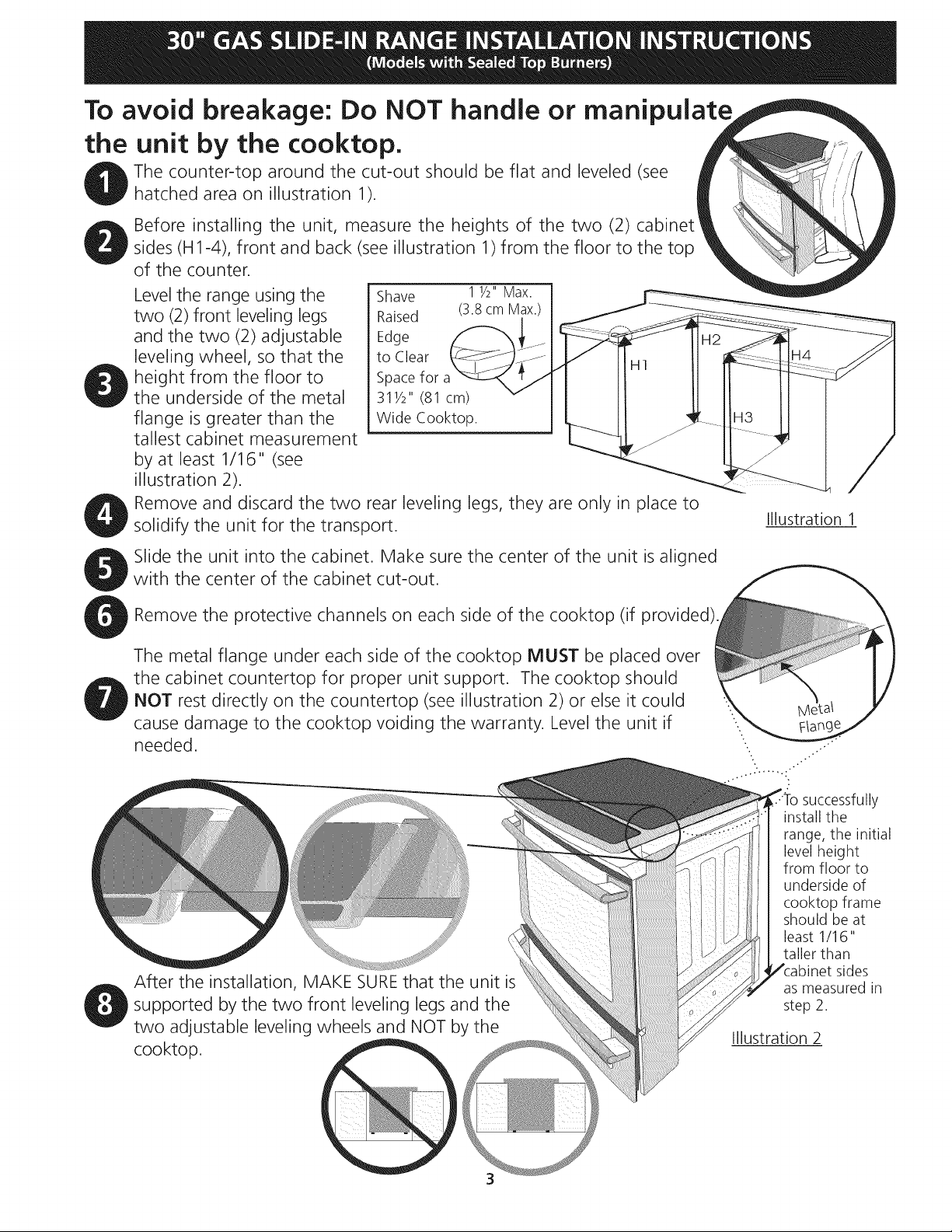
To avoid breakage: Do NOT handle or manipulate
the unit by the cooktop.
The counter-top around the cut-out should be flat and leveled (see
hatched area on illustration 1).
Before installing the unit, measure the heights of the two (2) cabinet
sides (H1-4), front and back (see illustration 1)from the floor to the top
of the counter.
Level the range using the Shave 11/2"Max. 1
two (2) front leveling legs Raised (3.8cmMax.)
and the two (2) adjustable Edge
leveling wheel, so that the to Clear
height from the floor to Space for
the underside of the metal 311/2" (81cm)
flange is greater than the Wide Cooktop.
tallest cabinet measurement
by at least 1/16" (see
illustration 2).
Remove and discard the two rear leveling legs, they are only in place to
solidify the unit for the transport.
I
Illustration 1
Slide the unit into the cabinet. Make sure the center of the unit is alignedwith the center of the cabinet cut-out.
Remove the protective channels on each side of the cooktop (if provided).
The metal flange under each side of the cooktop MUST be placed over
the cabinet countertop for proper unit support. The cooktop should
NOT rest directly on the countertop (see illustration 2) or else it could
cause damage to the cooktop voiding the warranty. Level the unit if
needed.
After the installation, MAKE SUREthat the unit is
supported by the two front leveling legs and the
two adjustable leveling wheels and NOT by the
cooktop.
successfully
install the
range, the initial
level height
from floor to
underside of
cooktop frame
should be at
least 1/16"
taller than
sides
as measured in
step 2.
Illustration 2
3
important Notes to the Installer
1. Read all instructions contained in these installation
instructions before installing range.
2. Remove all packing material from the oven
compartments before connecting the gas and
electrical supply to the range.
3. Observe all governing codes and ordinances.
4. Be sure to leave these instructions with the consumer.
5. Note: For operation at 2000 ft. elevations above see
level, appliance rating shall be reduced by 4 percent
for each additional 1000 ft.
important Note to the Consumer
Keep these instructions with your Use & Care Guide for
future reference.
IMPORTANT SAFETY
INSTRUCTION
Installation of this range must conform with local codes
or, in the absence of local codes, with the National Fuel
Gas Code ANSI Z223.1/NFPA .54-latest edition.
This range has been design certified by CSA
International. As with any appliance using gas and
generating heat, there are certain safety precautions you
should follow. You will find them in the Use and Care
Guide, read it carefully.
• Be sure your range is installed and grounded
properly by a qualified installer or service
technician.
This range must be electrically grounded in
accordance with local codes or, in their absence,
with the National Electrical Code ANSI/NFPA No.
70--latest edition. See Grounding Instructions.
Before installing the range in an area covered
with linoleum or any other synthetic floor
covering, make sure the floor covering can
withstand heat at least 90°F above room
temperature without shrinking, warping or
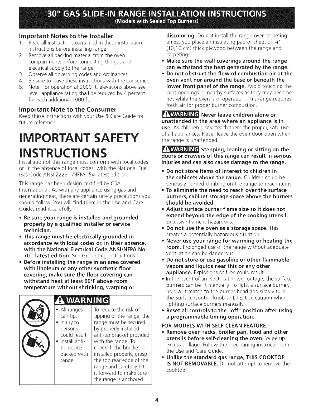
To reduce the risk of
tipping of the range, the
range must be secured
by properly installed
anti-tip bracket provided
with the range. To
check if the bracket is
installed properly, grasp
the top rear edge of the
range and carefully tilt
it forward to make sure
the range is anchored.
@
All ranges
can tip.
Injury to
persons
could result.
Install anti-
tip device
packed with
range.
discoloring. Do not install the range over carpeting
unless you place an insulating pad or sheet of 1/4"
(10,16 cm) thick plywood between the range and
carpeting.
Make sure the wall coverings around the range
can withstand the heat generated by the range.
Do not obstruct the flow of combustion air at the
oven vent nor around the base or beneath the
lower front panel of the range. Avoid touching the
vent openings or nearby surfaces as they may become
hot while the oven is in operation. This range requires
fresh air for proper burner combustion.
Never leave children alone or
unattended in the area where an appliance is in
use. As children grow, teach them the proper, safe use
of all appliances. Never leave the oven door open when
the range is unattended.
Stepping, leaning or sitting on the
doors or drawers of this range can result in serious
injuries and can also cause damage to the range.
Do not store items of interest to children in
the cabinets above the range. Children could be
seriously burned climbing on the range to reach items.
To eliminate the need to reach over the surface
burners, cabinet storage space above the burners
should be avoided.
• Adjust surface burner flame size so it does not
extend beyond the edge of the cooking utensil.
Excessiveflame is hazardous.
Do not use the oven as a storage space. This
creates a potentially hazardous situation.
Never use your range for warming or heating the
room. Prolonged use of the range without adequate
ventilation can be dangerous.
Do not store or use gasoline or other flammable
vapors and liquids near this or any other
appliance. Explosions or fires could result.
In the event of an electrical power outage, the surface
burners can be lit manually. To light a surface burner,
hold a lit match to the burner head and slowly turn
the Surface Control knob to LITE. Use caution when
lighting surface burners manually.
Reset all controls to the "off" position after using
a programmable timing operation.
FOR MODELS WITH SELF-CLEAN FEATURE:
• Remove oven racks, broiler pan, food and other
utensils before self-cleaning the oven. Wipe up
excess spillage. Follow the precleaning instructions in
the Use and Care Guide.
Unlike the standard gas range, THIS COOKTOP
IS NOT REMOVABLE, Do not attempt to remove the
cooktop.
4
Cabinet Construction
To eliminate the risk of cabinet burns
and fire, do not have cabinet storage space above the
range. If there is cabinet storage space above range,
reduce risk by installing a range hood that projects
horizontally a minimum of 5" (12.7 cm) beyond the
bottom of the cabinet.
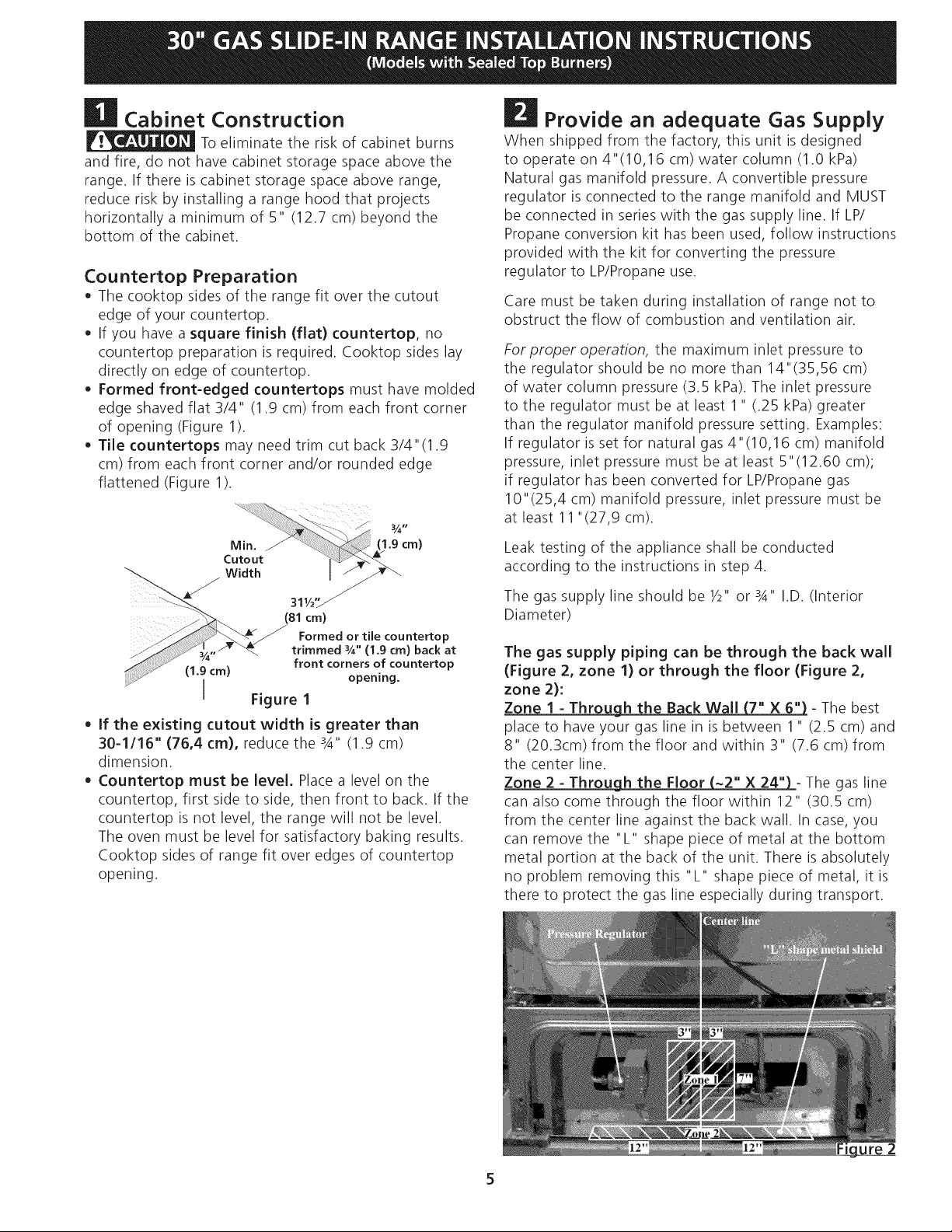
Countertop Preparation
• The cooktop sides of the range fit over the cutout
edge of your countertop.
• If you have a square finish (flat) countertop, no
countertop preparation is required. Cooktop sides lay
directly on edge of countertop.
• Formed front-edged countertops must have molded
edge shaved flat 3/4" (1.9 cm) from each front corner
of opening (Figure 1).
• Tile countertops may need trim cut back 3/4"(1.9
cm) from each front corner and/or rounded edge
flattened (Figure 1).
J
(81cm)
Formed or tile countertop
trimmed _A"(1.9 cm) back at
front corners of cou ntertop
(1.9 cm) opening.
I Figure 1
• If the existing cutout width is greater than
30-1/16" (76,4 cm), reduce the 3A" (1.9 cm)
dimension.
• Countertop must be level, Place a level on the
countertop, first side to side, then front to back. If the
countertop is not level, the range will not be level.
The oven must be level for satisfactory baking results.
Cooktop sides of range fit over edges of countertop
opening.
m
f-q Provide an adequate Gas Supply
When shipped from the factory, this unit is designed
to operate on 4"(10,16 cm) water column (1.0 kPa)
Natural gas manifold pressure. A convertible pressure
regulator is connected to the range manifold and MUST
be connected in series with the gas supply line. If LP/
Propane conversion kit has been used, follow instructions
provided with the kit for converting the pressure
regulator to LP/Propane use.
Care must be taken during installation of range not to
obstruct the flow of combustion and ventilation air.
Forproper operation, the maximum inlet pressure to
the regulator should be no more than 14"(35,56 cm)
of water column pressure (3.5 kPa). The inlet pressure
to the regulator must be at least 1" (.25 kPa) greater
than the regulator manifold pressure setting. Examples:
If regulator is set for natural gas 4" (10,16 cm) manifold
pressure, inlet pressure must be at least 5"(12.60 cm);
if regulator has been converted for LP/Propane gas
10"(25,4 cm) manifold pressure, inlet pressure must be
at least 11 "(27,9 cm).
Leak testing of the appliance shall be conducted
according to the instructions in step 4.
The gas supply line should be 1/2"or 3A" I.D. (Interior
Diameter)
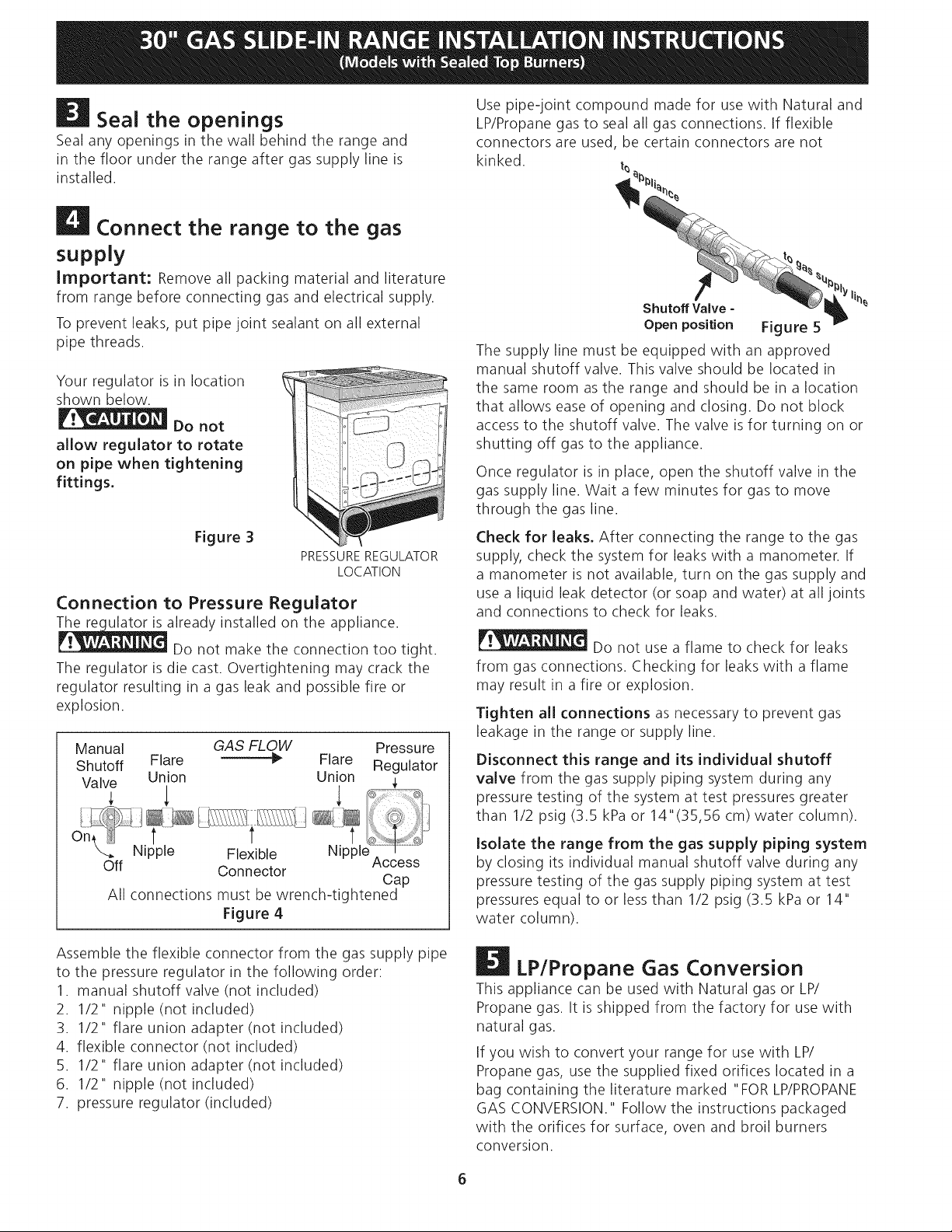
The gas supply piping can be through the back wall
(Figure 2, zone I) or through the floor (Figure 2,
zone 2):
Zone I - Through the Back Wall (7" X 6") - The best
place to have your gas line in is between 1" (2.5 cm) and
8" (20.3cm) from the floor and within 3" (7.6 cm) from
the center line.
Zone 2 - Through the Floor (~2" X 24") - The gas line
can also come through the floor within 12" (30.5 cm)
from the center line against the back wall. In case, you
can remove the "L" shape piece of metal at the bottom
metal portion at the back of the unit. There is absolutely
no problem removing this "L" shape piece of metal, it is
there to protect the gas line especially during transport.
Seal the openings
Seal any openings in the wall behind the range and
in the floor under the range after gas supply line is
installed.
N
Connect the range to the gas
supply
Important: Remove all packing material and literature
from range before connecting gas and electrical supply.
To prevent leaks, put pipe joint sealant on all external
pipe threads.
Your regulator is in location
shown below.
Do not
allow regulator to rotate
on pipe when tightening
fittings,
Use pipe-joint compound made for use with Natural and
LP/Propane gas to seal all gas connections. If flexible
connectors are used, be certain connectors are not
kinked.
li%
The supply line must be equipped with an approved
manual shutoff valve. This valve should be located in
the same room as the range and should be in a location
that allows ease of opening and closing. Do not block
access to the shutoff valve. The valve is for turning on or
shutting off gas to the appliance.
Once regulator is in place, open the shutoff valve in the
gas supply line. Wait a few minutes for gas to move
through the gas line.
Figure 3
PRESSUREREGULATOR
LOCATION
Connection to Pressure Regulator
T_already installed on the appliance.
The regulator is die cast. Overtightening may crack the
regulator resulting in a gas leak and possible fire or
explosion.
Manual GAS FLOW Pressure
Shutoff Flare _1_ Flare Regulator
Valve Union Union _.
Do not make the connection too tight.
II ii'2
Off Connector
All connections must be wrench-tightened
Figure 4
Assemble the flexible connector from the gas supply pipe
to the pressure regulator in the following order:
1. manual shutoff valve (not included)
2. 1/2" nipple (not included)
3. 1/2" flare union adapter (not included)
4. flexible connector (not included)
5. 1/2" flare union adapter (not included)
6. 1/2" nipple (not included)
7. pressure regulator (included)
Access
Cap
Check for leaks, After connecting the range to the gas
supply, check the system for leaks with a manometer. If
a manometer is not available, turn on the gas supply and
use a liquid leak detector (or soap and water) at all joints
and connections to check for leaks.
Do not use a flame to check for leaks
from gas connections. Checking for leaks with a flame
may result in a fire or explosion.
Tighten all connections as necessary to prevent gas
leakage in the range or supply line.
Disconnect this range and its individual shutoff
valve from the gas supply piping system during any
pressure testing of the system at test pressures greater
than 1/2 psig (3.5 kPa or 14"(35,56 cm) water column).
Isolate the range from the gas supply piping system
by closing its individual manual shutoff valve during any
pressure testing of the gas supply piping system at test
pressures equal to or less than 1/2 psig (3.5 kPa or 14"
water column).
LP/Propane Gas Conversion
This appliance can be used with Natural gas or LP/
Propane gas. It is shipped from the factory for use with
natural gas.
If you wish to convert your range for use with LP/
Propane gas, use the supplied fixed orifices located in a
bag containing the literature marked "FOR LP/PROPANE
GAS CONVERSION." Follow the instructions packaged
with the orifices for surface, oven and broil burners
conversion.
Theconversionmustbeperformedbya qualifiedservice
technicianinaccordancewiththemanufacturer's
instructionsandalllocalcodesandrequirements.Failure
tofollowtheseinstructionscouldresultinseriousinjury
orpropertydamage.Thequalifiedagencyperforming
thisworkassumesresponsibilityfortheconversion.
Failureto maketheappropriate
conversioncanresultinseriouspersonalinjuryand
propertydamage.
| Electrical Requirements
120 volt, 60 Hertz, properly grounded dedicated circuit
protected by a 15 amp circuit breaker or time delay fuse.
Note: Not recommended to be installed with a Ground
Fault Interrupt (GFI).
Do not use an extension cord with this range.
Grounding Instructions
IMPORTANT Pleaseread carefully.
For personal safety, this appliance must be properly
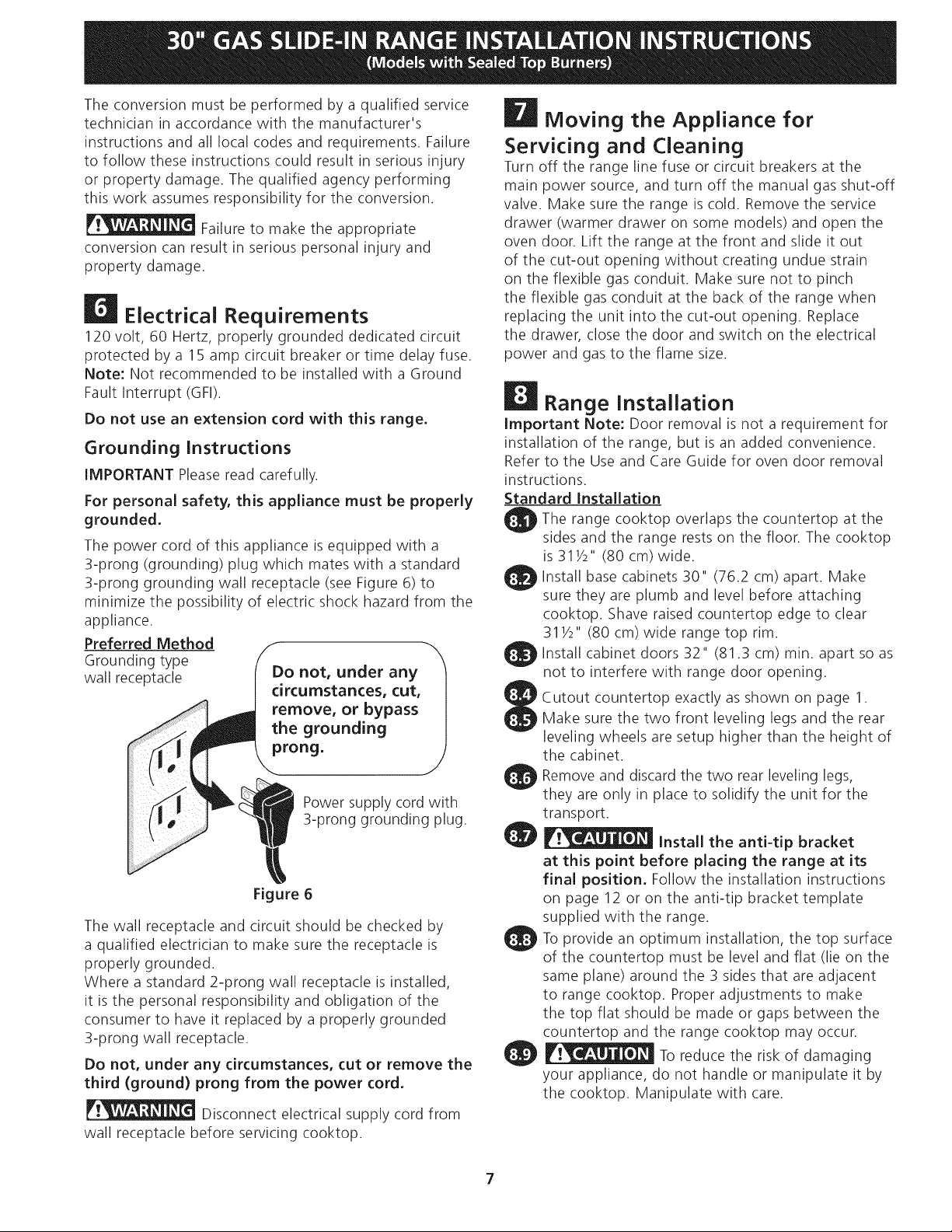
grounded.
The power cord of this appliance isequipped with a
3-prong (grounding) plug which mates with a standard
3-prong grounding wall receptacle (see Figure 6) to
minimize the possibility of electric shock hazard from the
appliance.
Preferred Method
Grounding type
wall receptacle
The wall receptacle and circuit should be checked by
a qualified electrician to make sure the receptacle is
properly grounded.
Where a standard 2-prong wall receptacle is installed,
it is the personal responsibility and obligation of the
consumer to have it replaced by a properly grounded
3-prong wall receptacle.
Do not, under any circumstances, cut or remove the
third (ground) prong from the power cord.
Disconnect electrical supply cord from
wall receptacle before servicing cooktop.
Do not, under any
circumstances, cut,
remove, or bypass
the grounding
prong.
Power supply cord with
3-prong grounding plug.
Figure 6
x
Moving the Appliance for
Servicing and Cleaning
Turn off the range line fuse or circuit breakers at the
main power source, and turn off the manual gas shut-off
valve. Make sure the range is cold. Remove the service
drawer (warmer drawer on some models) and open the
oven door. Lift the range at the front and slide it out
of the cut-out opening without creating undue strain
on the flexible gas conduit. Make sure not to pinch
the flexible gas conduit at the back of the range when
replacing the unit into the cut-out opening. Replace
the drawer, dose the door and switch on the electrical
power and gas to the flame size.
Range Installation
Important Note: Door removal is not a requirement for
installation of the range, but is an added convenience.
Refer to the Use and Care Guide for oven door removal
instructions.
Standard Installation
_DI The cooktop overlaps the at the
_ Install base cabinets 30" (76.2 cm) Make
_}1t Install cabinet doors 32" (81.3 cm) min.
_ emove and discard the two rear leveling legs,
O _ Install the anti-tip bracket
_To provide an optimum installation, top
_11_ To reduce the risk of damaging
range
sides and the range rests on the floor. The cooktop
is 311/2'` (80 cm) wide.
sure they are plumb and level before attaching
cooktop. Shave raised countertop edge to clear
311/2" (80 cm) wide range top rim.
not to interfere with range door opening.
Cutout countertop exactly as shown on page 1.
Make sure the two front leveling legs and the rear
leveling wheels are setup higher than the height of
the cabinet.
they are only in place to solidify the unit for the
transport.
at this point before placing the range at its
final position. Follow the installation instructions
on page 12 or on the anti-tip bracket template
supplied with the range.
of the countertop must be level and flat (lie on the
same plane) around the 3 sides that are adjacent
to range cooktop. Proper adjustments to make
the top flat should be made or gaps between the
countertop and the range cooktop may occur.
your appliance, do not handle or manipulate it by
the cooktop. Manipulate with care.
countertop
apart.
apart
the surface
SO 8S
7
Position infrontofthecabinetrange
sure
_c Make thattheundersideofthe
leafsthecountertop.Ifnecessary,raisetheunit
opening.
cooktop
byloweringthefrontlevelinglegsandtheback
levelingwheels.
_t Levelthe (seesection9).Thefloorwhere
herangeisto beinstalledmustbelevel.Follow
range
theinstructionsunder"LevelingtheRange".
Slidethe intothecutout
Installation With Backguard
The cutout depth of (21 3/4" (55.2 cm)Min., 22 1/8"
(56.2cm) Max.) needs to be increased to 24" (61 cm)
when installing a backguard.
Installation With End Panel
A End Panel kit can be ordered through a Service
Center.
Installation With Side Panels
A Side Panels kit can be ordered through a Service
Center.
Install cabinet doors 32" (81.3 cm) min. apart so as
not to interfere with range door opening.
range
If Accessories Needed :
opening.
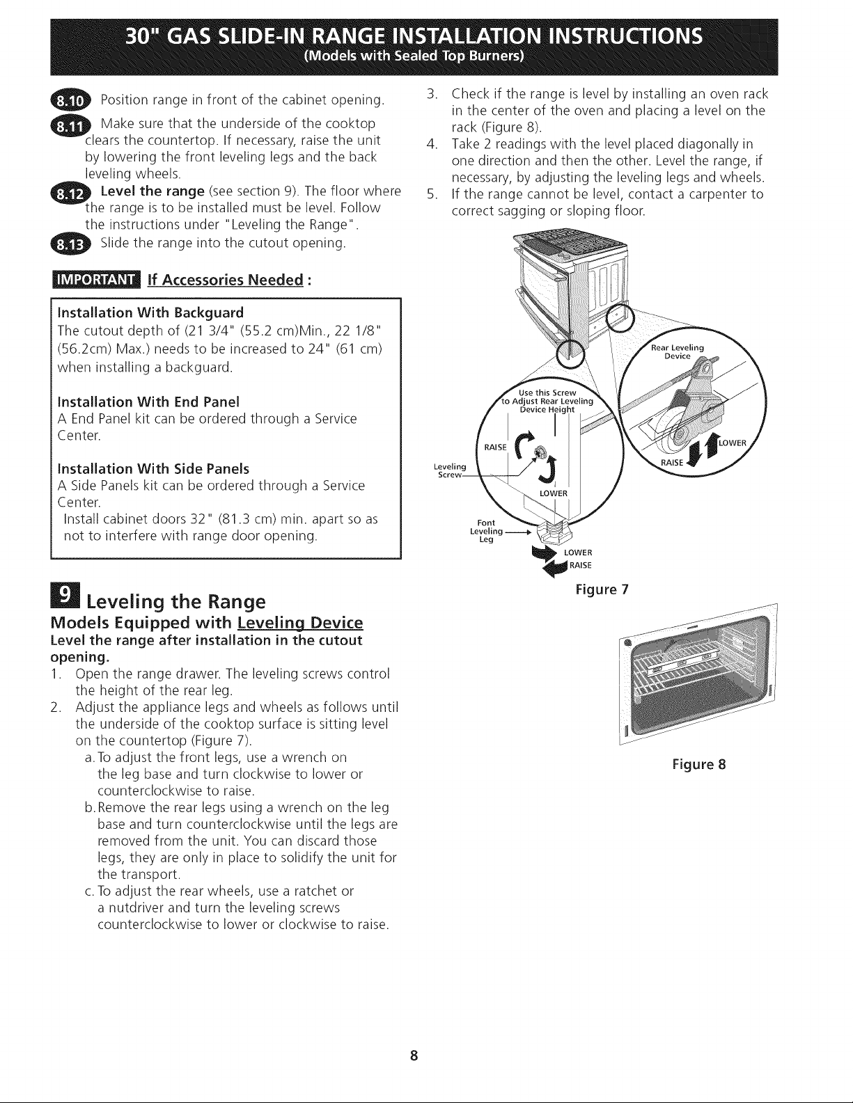
3. Checkif therangeislevelbyinstallinganovenrack
inthecenteroftheovenandplacingalevelonthe
rack(Figure8).
4. Take2 readingswiththelevelplaceddiagonallyin
onedirectionandthentheother.Leveltherange,if
necessary,byadjustingthelevelinglegsandwheels.
5. Iftherangecannotbelevel,contactacarpenterto
correctsaggingorslopingfloor.
Font
Leveling
Leg
LOWER
RAISE
Leveling the Range
Models Equipped with Leveling Device
Level the range after installation in the cutout
opening.
1. Open the range drawer. The leveling screws control
the height of the rear leg.
2. Adjust the appliance legs and wheels as follows until
the underside of the cooktop surface is sitting level
on the countertop (Figure 7).
a.To adjust the front legs, use a wrench on
the leg base and turn clockwise to lower or
counterclockwise to raise.
b.Remove the rear legs using a wrench on the leg
base and turn counterclockwise until the legs are
removed from the unit. You can discard those
legs, they are only in place to solidify the unit for
the transport.
c. Toadjust the rear wheels, use a ratchet or
a nutdriver and turn the leveling screws
counterclockwise to lower or clockwise to raise.
Figure 7
Figure 8
Check Operation
Refer to the Use and Care Guide packaged with the
range for operating instructions and for care and
cleaning of your range.
Do not touch the elements or burners. They may be hot
enough to cause burns.
Remove all packaging from the oven before testing.
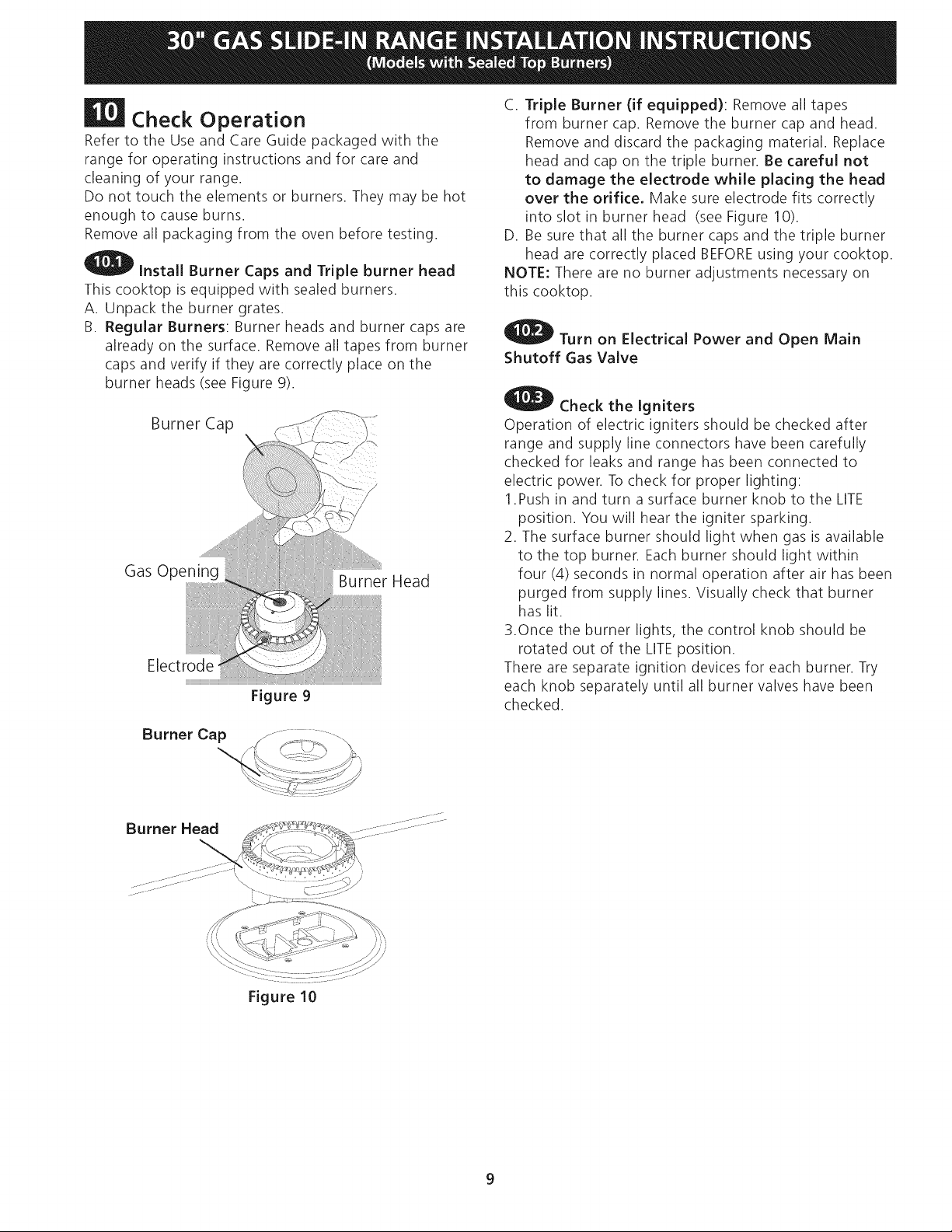
Install Burner Caps and Triple burner head
This cooktop is equipped with sealed burners.
A. Unpack the burner grates.
B. Regular Burners: Burner heads and burner caps are
already on the surface. Remove all tapes from burner
caps and verify if they are correctly place on the
burner heads (see Figure 9).
Burner Cap
Gas Opening
Electrode
Figure 9
Burner Head
C. Triple Burner (if equipped): Remove all tapes
from burner cap. Remove the burner cap and head.
Remove and discard the packaging material. Replace
head and cap on the triple burner. Be careful not
to damage the electrode while placing the head
over the orifice. Make sure electrode fits correctly
into slot in burner head (see Figure 10).
D. Be sure that all the burner caps and the triple burner
head are correctly placed BEFOREusing your cooktop.
NOTE: There are no burner adjustments necessary on
this cooktop.
O Turn on Electrical Power and Open Main
Shutoff Gas Valve
Check the Igniters
Operation of electric igniters should be checked after
range and supply line connectors have been carefully
checked for leaks and range has been connected to
electric power. To check for proper lighting:
1.Push in and turn a surface burner knob to the LITE
position. You will hear the igniter sparking.
2. The surface burner should light when gas is available
to the top burner. Each burner should light within
four (4) seconds in normal operation after air has been
purged from supply lines. Visually check that burner
has lit.
3.Once the burner lights, the control knob should be
rotated out of the LITEposition.
There are separate ignition devices for each burner. Try
each knob separately until all burner valves have been
checked.
Burner Head
Figure 10
9
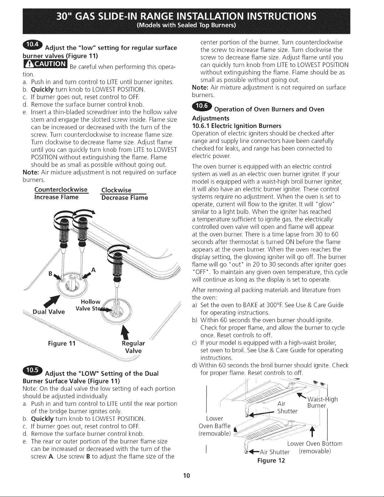
Adjustthe "low" settingfor regularsurface
burnervalves(Figure11)
Becarefulwhenperformingthisopera-
tion.
a. Pushinandturncontrolto LITEuntilburnerignites.
b. QuicklyturnknobtoLOWESTPOSITION.
c. If burnergoesout,resetcontroltoOFF.
d. Removethesurfaceburnercontrolknob.
e. Insertathin-bladedscrewdriverintothehollowvalve
stemandengagetheslottedscrewinside.Flamesize
canbeincreasedordecreasedwiththeturnofthe
screw.Turncounterclockwisetoincreaseflamesize.
Turnclockwiseto decreaseflamesize.Adjustflame
untilyoucanquicklyturnknobfromLITEto LOWEST
POSITIONwithoutextinguishingtheflame.Flame
shouldbeassmallaspossiblewithoutgoingout.
Note:Airmixtureadjustmentisnotrequiredonsurface
burners.
Cou nterdockwise
Increase Flame
_,_,-Dual Valve
"_,,_,
Figure 11 _ Regular
O Adjust the "LOW" Setting of the Dual
Burner Surface Valve (Figure 11)
Note: On the dual valve the low setting of each portion
should be adjusted individually.
a. Push in and turn control to LITEuntil the rear portion
of the bridge burner ignites only.
b. Quickly turn knob to LOWEST POSITION.
c. If burner goes out, reset control to OFF.
d. Remove the surface burner control knob.
e. The rear or outer portion of the burner flame size
can be increased or decreased with the turn of the
screw A. Use screw Bto adjust the flame size of the
Valve
Clockwise
Decrease Flame
_ Valve
_- ...........J
center portion of the burner. Turn counterclockwise
the screw to increase flame size. Turn clockwise the
screw to decrease flame size. Adjust flame until you
can quickly turn knob from LITEto LOWEST POSITION
without extinguishing the flame. Flame should be as
small as possible without going out.
Note: Air mixture adjustment is not required on surface
burners.
Operation of Oven Burners and Oven
Adjustments
10.6.1 Electric Ignition Burners
Operation of electric igniters should be checked after
range and supply line connectors have been carefully
checked for leaks, and range has been connected to
electric power.
The oven burner is equipped with an electric control
system aswell as an electric oven burner igniter. If your
model is equipped with a waist-high broil burner igniter,
it will also have an electric burner igniter. These control
systems require no adjustment. When the oven is set to
operate, current will flow to the igniter. It will "glow"
similar to a light bulb. When the igniter has reached
a temperature sufficient to ignite gas, the electrically
controlled oven valve will open and flame will appear
at the oven burner. There is a time lapsefrom 30 to 60
seconds after thermostat is turned ON before the flame
appears at the oven burner. When the oven reachesthe
display setting, the glowing igniter will go off. The burner
flame will go "out" in 20 to 30 seconds after igniter goes
"OFF". Tomaintain any given oven temperature, this cycle
will continue as long as the display is set to operate.
After removing all packing materials and literature from
the oven:
a) Set the oven to BAKE at 300% See Use & Care Guide
for operating instructions.
b) Within 60 seconds the oven burner should ignite.
Check for proper flame, and allow the burner to cycle
once. Resetcontrols to off.
c) If your model is equipped with a high-waist broiler,
set oven to broil. See Use & Care Guide for operating
instructions.
d) Within 60 seconds the broil burner should ignite. Check
for proper flame. Resetcontrols to off.
s"
Air
Shutter
Lower
Oven Baffle
(removable)
Lower Oven Bottom
Shutter (removable)
Figure 12
¢Vaist-High
Burner
10
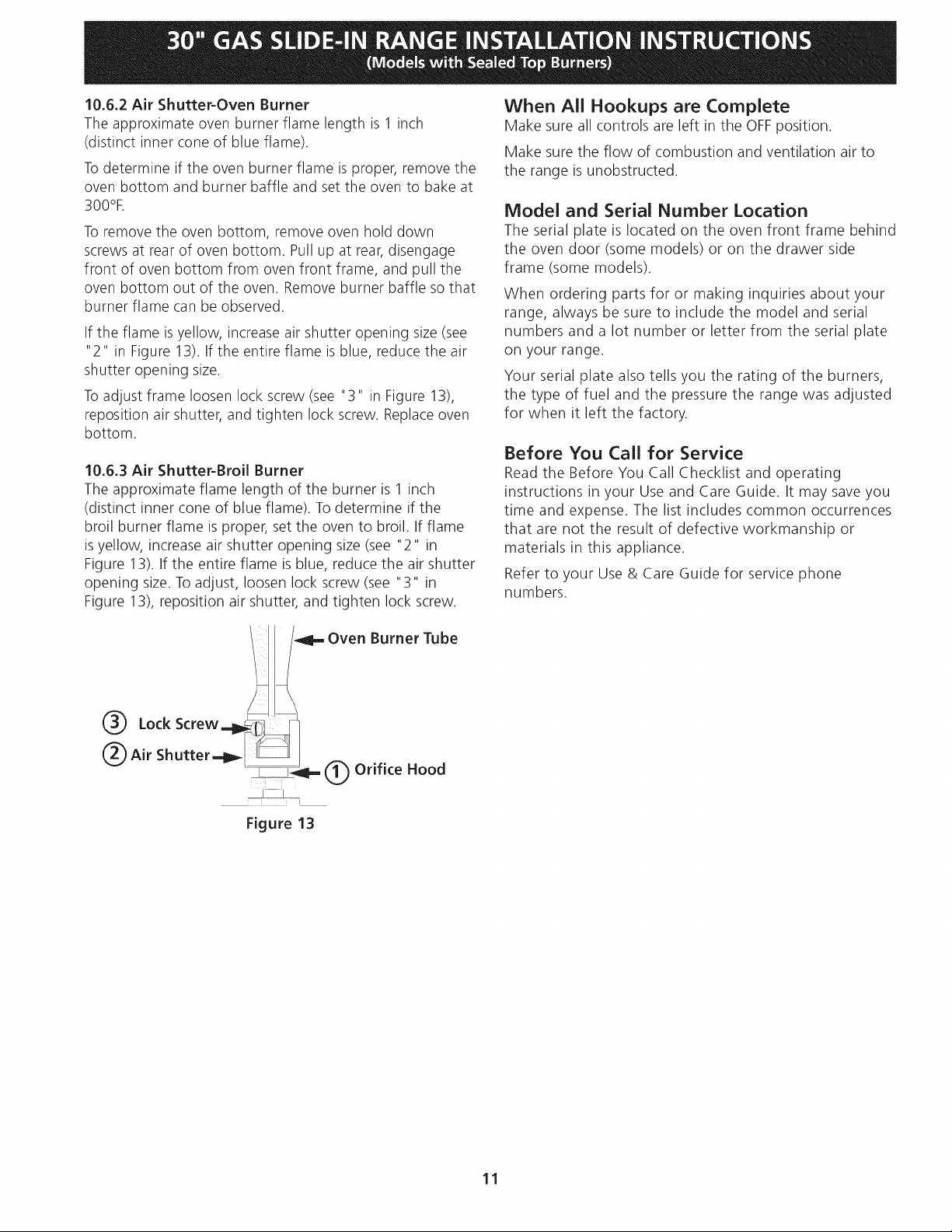
10.6.2Air Shutter-OvenBurner
Theapproximateovenburnerflamelengthis1inch
(distinctinnerconeofblueflame).
Todetermineiftheovenburnerflameisproper,removethe
ovenbottomandburnerbaffleandsettheoventobakeat
300°F.
Toremovetheovenbottom,removeovenholddown
screwsatrearofovenbottom.Pullupatrear,disengage
frontofovenbottomfromovenfrontframe,andpullthe
ovenbottomoutoftheoven.Removeburnerbafflesothat
burnerflamecanbeobserved.
Iftheflameisyellow,increaseairshutteropeningsize(see
"2" inFigure13).Iftheentireflameisblue,reducetheair
shutteropeningsize.
Toadjustframeloosenlockscrew(see"3" inFigure13),
repositionairshutter,andtightenlockscrew.Replaceoven
bottom.
10.6.3Air Shutter-BroilBurner
Theapproximateflamelengthoftheburneris1inch
(distinctinnerconeof blueflame).Todetermineifthe
broilburnerflameisproper,settheoventobroil.Ifflame
isyellow,increaseairshutteropeningsize(see"2" in
Figure13).Iftheentireflameisblue,reducetheairshutter
openingsize.Toadjust,loosenlockscrew(see"3" in
Figure13),repositionairshutter,andtightenlockscrew.
When All Hookups are Complete
Make sure all controls are left in the OFFposition.
Make sure the flow of combustion and ventilation air to
the range is unobstructed.
Model and Serial Number Location
The serial plate is located on the oven front frame behind
the oven door (some models) or on the drawer side
frame (some models).
When ordering parts for or making inquiries about your
range, always be sure to include the model and serial
numbers and a lot number or letter from the serial plate
on your range.
Your serial plate also tells you the rating of the burners,
the type of fuel and the pressure the range was adjusted
for when it left the factory.
Before You Call for Service
Read the Before You Call Checklist and operating
instructions in your Use and Care Guide. It may save you
time and expense. The list includes common occurrences
that are not the result of defective workmanship or
materials in this appliance.
Refer to your Use & Care Guide for service phone
numbers.
Lock Screw
Air Shutter-_
Burner Tube
Orifice Hood
Figure 13
11
Anti-Tip Brackets Installation
instructions
To reduce the risk of tipping of the
range, the range must be secured to the floor by properly
installed anti-tip bracket and screws packed with the
range. These parts are located in the oven. Failure to
install the anti-tip bracket will allow the range to tip over
if excessiveweight is placed on an open door or if a child
climbs upon it. Serious injury might result from spilled hot
liquids or from the range itself.
Follow the instructions below to install the anti-tip
brackets.
If range is ever moved to a different location, the anti-
tip brackets must also be moved and installed with the
range.
Tools Required:
Adjustable Wrench
Ratchet
Drill & 1/8"(0,32 cm) bit
5/16" (0,8 cm) Nutdriver
Level
The anti-tip bracket attaches to the floor at the back of
the range to prevent range from tipping. When fastening
bracket to the floor, be sure that screws do not penetrate
electrical wiring or plumbing. The screws provided will
work in either wood or concrete.
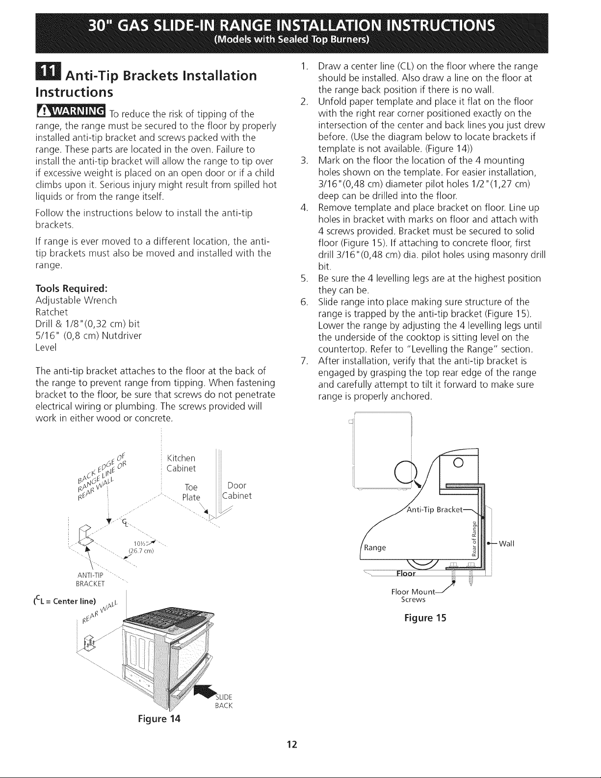
1. Draw a center line (CL) on the floor where the range
should be installed. Also draw a line on the floor at
the range back position if there is no wall.
2. Unfold paper template and place it flat on the floor
with the right rear corner positioned exactly on the
intersection of the center and back lines you just drew
before. (Use the diagram below to locate brackets if
template is not available. (Figure 14))
3. Mark on the floor the location of the 4 mounting
holes shown on the template. For easier installation,
3/16"(0,48 cm) diameter pilot holes 1/2"(1,27 cm)
deep can be drilled into the floor.
4. Remove template and place bracket on floor. Line up
holes in bracket with marks on floor and attach with
4 screws provided. Bracket must be secured to solid
floor (Figure 15). If attaching to concrete floor, first
drill 3/16" (0,48 cm) dia. pilot holes using masonry drill
bit.
5. Be sure the 4 levelling legs are at the highest position
they can be.
6. Slide range into place making sure structure of the
range is trapped by the anti-tip bracket (Figure 15).
Lower the range by adjusting the 4 levelling legs until
the underside of the cooktop is sitting level on the
countertop. Refer to "Levelling the Range" section.
7. After installation, verify that the anti-tip bracket is
engaged by grasping the top rear edge of the range
and carefully attempt to tilt it forward to make sure
range is properly anchored.
(eL = Center line) V_#LI_
Door
Cabinet
Floor Mo
Screws
Figure 15
BACK
Figure 14
12
 Loading...