

Electrolux EI30DS55JS2, EI30DS55LBA, EI30DS55LBB, EI30DS55LWA, EI30DS55LWB Installation Guide
...
iNSTALLATiON AND SERVICE MUST BE PERFORMED BY A QUALiFiED iNSTALLER.
iMPORTANT: SAVE FOR LOCAL ELECTRICAL iNSPECTOR'S USE.
READ AND SAVE THESE INSTRUCTIONS FOR FUTURE REFERENCE.
if the information in this manual is not followed exactly, a fire
or explosion may result causing property damage, personal injury or death.
FOR YOUR SAFETY:
-- Do not store or use gasoline or other flammable vapors and liquids in the
vicinity of this or any other appliance.
-- WHAT TO DO IF YOU SMELL GAS:
• Do not try to light any appliance.
Do not touch any electrical switch; do not use any phone in your building.
Immediately call your gas supplier from a neighbor's phone. Follow the
gas supplier's instructions.
If you cannot reach your gas supplier, call the fire department.
-- Installation and service must be performed by a qualified installer, service
agency or the gas supplier.
Appliances Installed in the
state of Massachusetts:
This Appliance can only
be installed in the state of
Massachusetts by a Massachusetts
licensed plumber or gasfitter.
This appliance must be installed
with a three (3) foot / 36 in. long
flexible gas connector.
A"T" handle type manual gas
valve must be installed in the gas
supply line to this appliance.
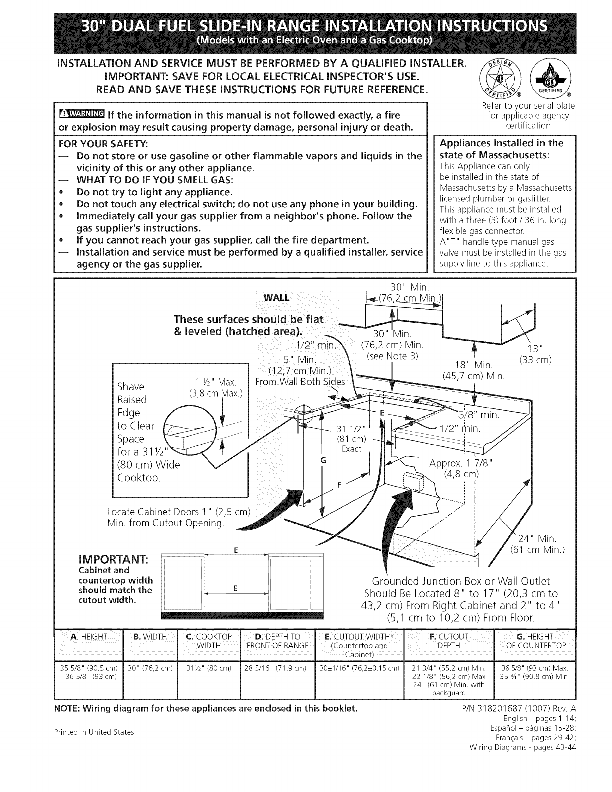
30" Min.
WALL I_t-(76 2 cm Min.)l
'_1
These surfaces should be flat _ _ _'_'l
& leveled (hatched area), - _30" 'Min. [
Referto your serialplate
for applicableagency
certification
5" M n \ (seeNote 3) .... _ ,. (33 cm)
(12 7 cm Mm.) \ ..... ;_.
". /;5 Mn
Shave 1 1/2"Max. From Wall Both S_es \--'_"_"_, _ tqb,/ c.rn_ivun.
Rased (3,8 cm .Max.)
to Clear __ _"_ _'_m_n.' ..... ,-_
fora 31Y2"_ f _ _ Exact I -h_f...__
(80 cm) Wide _ G l i _ Approx. 1 7/8"
Cooktop. _ j ¢=:::_ (4,8 cm) _,
Locate Cabinet Doors 1" (2,5 cm) __1 It,--''/ / _f----_ ........... / /
Min. from Cutout Opening. _ _/ r_./ .............. /'N_
__ V_ _/ /-24" Min.
.........................._ E ,_............................................_' LL....... _ , / (61 cm Min.)
IMPORTANT: i i i _ -'1
Cabinet and j J i
countertop width j i i Grounded Junction Box or Wall Outlet
should match the _ E ,_ . .
cutoutwdth , _ Should Be Located.8 to. 17. (20,3.cm to
.............., ...............................................#4,z cm#Prom mlgn]: LaDine]: ana z [o #
(5,1 cm to 10,2 cm) From Floor.
A. HEIGHT B. WIDTH
35 5/8" (90.5 cm) 30" (76,2 cm)
- 36 5/8" (93 cm)
NOTE: Wiring diagram for these appliances are enclosed in this booklet.
Printed in United States
C, CO©KTOP
31Y2" (80 cm) 28 5/16" (71,9 cm) 30_+1/16" (76,2_+0,15 cm) 21 3/4" (55,2 cm) Min. 36 5/8" (93 cm) Max.
D: DEPTHTo
FRONT OF RANGE
E. CUTOUT W!DTH* I Fi CUTOUT G. HEIGHT
(Countert0p and DEPTH ' OFCOUNTERTOP
Cabinet) -
22 1/8" (56,2 cm) Max 35 3A,,(90,8 cm) Min.
24" (61 cm) Min. with
backguard
P/N318201687 (1007) Rev.A
Espaflol - p_iginas 15-28;
Fran_ais - pages 29-42;
Wiring Diagrams - pages 43-44
7
English - pages 1-14;
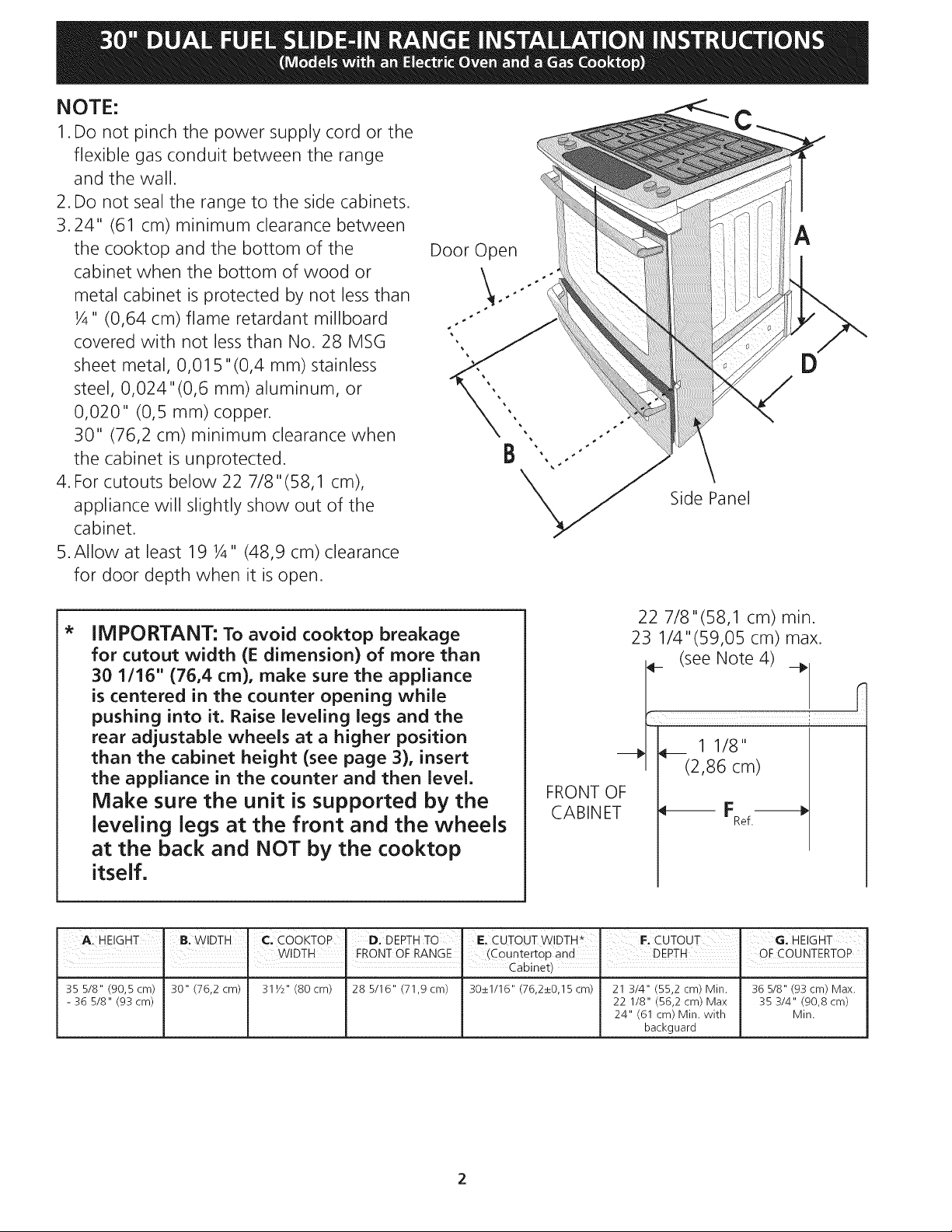
NOTE:
1. Do not pinch the power supply cord or the
flexible gas conduit between the range
and the wall.
2. Do not seal the range to the side cabinets.
_3.24" (61 cm) minimum clearance between
the cooktop and the bottom of the
cabinet when the bottom of wood or
metal cabinet is protected by not lessthan
¼" (0,64 cm) flame retardant millboard
covered with not less than No. 28 MSG
sheet metal, 0,01 5 "(0,4 mm) stainless
steel, 0,024"(0,6 mm) aluminum, or
0,020" (0,5 mm) copper.
30" (76,2 cm) minimum clearance when
the cabinet is unprotected.
4. For cutouts below 22 7/8"(58,1 cm),
appliance will slightly show out of the
cabinet.
5.Allow at least 19 ¼" (48,9 cm) clearance
for door depth when it is open.
A
Door Open
B
Side Panel
_t
IM PORTANT: To avoid cooktop breakage
22 7/8"(58,1 cm) min.
23 1/4"(59,05 cm) max.
for cutout width (E dimension) of more than
30 1/16" (76,4 cm), make sure the appliance
is centered in the counter opening while
pushing into it. Raise leveling legs and the
(see Note 4) __
rear adjustable wheels at a higher position
than the cabinet height (see page 3), insert
/ (2,86 cm)
the appliance in the counter and then level.
FRONT OF
Make sure the unit is supported by the
CABINET _ FRef--
leveling legs at the front and the wheels
at the back and NOT by the cooktop
itself.
AHEIGHT El:WIDTH clCooKToP" DiDEPTHTO E. CUTOUT WIDTH* F. cuTouT ] G. HEIGHT
WIDTH FRONT OF RANGE (CounteCc0p and DEPTH ] OF COUNTERTOP
i i i Cabinet) i i
35 5/8" (90,5 cm) 30" (76,2 cm) 31Y2" (80 cm) 28 5/16" (71,9 cm) 30_+1/16" (76,2_+0,15 cm) 21 3/4" (55,2 cm) Min. 36 5/8" (93 cm) Max.
- 36 5/8" (93 cm) 22 1/8" (56,2 cm) Max 35 3/4" (90,8 cm)
24" (61 cm) Min. with Min.
backguard
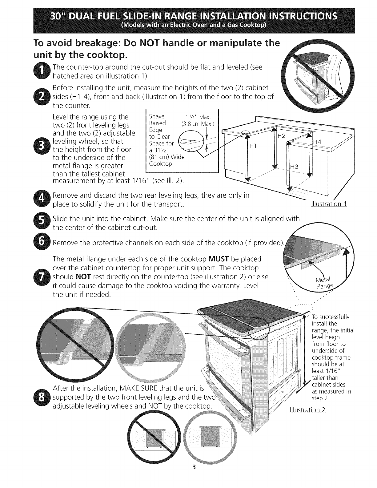
To avoid breakage: Do NOT handle or manipulate the
unit by the cooktop.
The counter-top around the cut-out should be flat and leveled (see
hatched area on illustration 1).
Before installing the unit, measure the heights of the two (2) cabinet
sides (H1-4), front and back (Illustration 1) from the floor to the top of
the counter•
Level the range using the
two (2) front leveling legs
and the two (2) adjustable
leveling wheel, so that
the height from the floor
to the underside of the
metal flange is greater
Shave
Raised
Edge
to Clear
Space for
a311h ''
(81 cm) Wide
Cooktop.
than the tallest cabinet
measurement by at least 1/1 6" (see III. 2).
Remove and discard the two rear leveling legs, they are only in
place to solidify the unit for the transport•
Slide the unit into the cabinet. Make sure the center of the unit is aligned with
the center of the cabinet cut-out.
1 1/2"Max.
(3.8cmMax.)
Illustration 1
Remove the protective channels on each side of the cooktop (if provided),
The metal flange under each side of the cooktop MUST be placed
over the cabinet countertop for proper unit support• The cooktop
should NOT rest directly on the countertop (see illustration 2) or else
it could cause damage to the cooktop voiding the warranty• Level
the unit if needed•
After the installation, MAKE SUREthat the unit is
supported by the two front leveling legs and the
adjustable leveling wheels and NOT by the cooktop.
Tosuccessfully
install the
range, the initial
level height
from floor to
underside of
cooktop frame
should be at
least 1/16"
taller than
sides
as measured in
step 2.
Illustration 2
3
important Notes to the Installer
1. Read all instructions contained in these installation
instructions before installing range.
2. Removeall packing material from the oven compartments
before connecting the gas and electrical supply to the
range.
3. Observe all governing codes and ordinances.
4. Be sure to leavethese instructions with the consumer.
5. Note: Foroperation at 2000 ft. elevations above see level,
appliance rating shall be reduced by 4 percent for each
additional 1000 ft.
important Note to the Consumer
Keep these instructions with your owner's guide for future
reference.
IMPORTANT SAFETY
INSTRUCTION
Installation of this range must conform with local codes
or, in the absence of local codes, with the National Fuel
Gas Code ANSI Z223. l--latest edition.
This range has been design certified by CSA
international. As with any appliance using gas and
generating heat, there are certain safety precautions you
should follow. You will find them in the Use and Care
Guide, read it carefully.
• Be sure your range is installed and grounded
properly by a qualified installer or service
technician.
This range must be electrically grounded in
accordance with local codes or, in their absence,
with the National Electrical Code ANSI/NFPA No.
70--latest edition. See Grounding Instructions.
The installation of appliances designed for manufactured
(mobile) home installation must conform with Manufactured
Home Construction and Safety Standard, title 24CFR, part
3280 [Formerly the Federal Standard for Mobile Home
Construction and Safety, title 24, HUD (part 280)] or
when such standard is not applicable, the Standard for
Manufactured Home Installation 1982 (Manufactured
Home Sites, Communities and Setups), ANSI Z225.1/NFPA
501A-latest edition, or with local codes.
To reduce the risk of tipping
of the range, the range
All ranges
can tip.
Injury to
persons
could result.
Install anti-
tip device
packed with
range.
must be secured by properly
installed anti-tip bracket
provided with the range.
To check if the bracket is
installed properly, grasp the
top rear edge of the range
and carefully tilt it forward
to make sure the range is
anchored.
Make sure the wall coverings around the range
can withstand the heat generated by the range.
Before installing the range in an area covered with
linoleum or any other synthetic floor covering,
make sure the floor covering can withstand heat
at least 90°F above room temperature without
shrinking, warping or discoloring. Do not install the
range over carpeting unless you place an insulating pad
or sheet of 1/4"(10,16 cm) thick plywood between the
range and carpeting.
Do not obstruct the flow of combustion air at the
oven vent nor around the base or beneath the
lower front panel of the range. Avoid touching the
vent openings or nearby surfaces as they may become
hot while the oven is in operation. This range requires
fresh air for proper burner combustion.
Never leave children alone or
unattended in the area where an appliance is in
use. As children grow, teach them the proper, safe use
of all appliances. Never leave the oven door open when
the range is unattended.
Stepping, leaning or sitting on the
doors or drawers of this range can result in serious
injuries and can also cause damage to the range.
Do not store items of interest to children in
the cabinets above the range. Children could be
seriously burned climbing on the range to reach items.
To eliminate the need to reach over the surface
burners, cabinet storage space above the burners
should be avoided.
Adjust surface burner flame size so it does not
extend beyond the edge of the cooking utensil.
Excessiveflame is hazardous.
Do not use the oven as a storage space. This
creates a potentially hazardous situation.
Never use your range for warming or heating the
room. Prolonged use of the range without adequate
ventilation can be dangerous.
Do not store or use gasoline or other flammable
vapors and liquids near this or any other
appliance. Explosions or fires could result.
In the event of an electrical power outage, the surface
burners can be lit manually. To light a surface burner,
hold a lit match to the burner head and slowly turn
the Surface Control knob to LITE.Use caution when
lighting surface burners manually.
Reset all controls to the "off" position after using
a programmable timing operation.
FOR MODELS WITH SELF-CLEAN FEATURE:
* Remove oven racks, broiler pan, food and other
utensils before self-cleaning the oven. Wipe up
excess spillage. Follow the precleaning instructions in
the Use and Care Guide.
4

N
| Power Supply Cord Kit (U.S.A.)
The user is responsible for connecting the power supply
cord to the connection block located behind the back
panel access cover.
This appliance may be connected by means of
permanent "hard wiring" (flexible armored or
nonmetallic shielded copper cable), or by means of a
power supply cord kit. Only a power supply cord kit
rated at 125/250 volts 30 Amps should be used. Cord
must have either 3 or 4 conductors.
For mobile homes, new installations, recreational
vehicles, or areas where local codes do not permit
grounding through neutral, a 4 conductor power supply
cord kit rated at 125/250 volts 30 Amps marked for use
with ranges should be used.
Terminals on end of wires must be either closed loop or
open-end spade lugs with upturned ends. Cord must
have strain-relief clamp.
m
Factory Connected Power Supply
Cord (Canada only)
This range is equipped with a factory-connected power
cord (see Figure 1). Cord must be connected to a
grounded 120/240 volt or 120/208 volt range outlet. If
not outlet is available, have one installed by a qualified
electrician.
Figure I
NOTE: Electric Slide-in Range is shipped from factory
with 1 1/8" (2.9 cm) dia. hole as shown on figure 3. If a
larger hole is required, punch out the knockout.
Breaker Size:
On a unit with 4800W or less at 240V (see serial plate),
a 20A circuit breaker or time-delay fuse is recommended
on both side of the line (red and black wire). DO NOT
fuse the neutral (white wire) or the ground (green or
bare wire).
On a unit with higher than 4800W at 240V (see serial
plate), follow the above recommendations but use a 30A
circuit breaker or time-delay fuse.
Risk of fire or electrical shock exists
if an incorrect size range cord kit is used, the
Installation Instructions are not followed, or the
strain relief bracket is discarded,
Do not loosen the nuts which secure
the factory-installed range wiring to terminal block
while connecting range, Electrical failure or loss of
electrical connection may occur.
Electrical Shock Hazard
• Electrical ground is required on this appliance,
• Do not connect to the electrical supply until
appliance is permanently grounded.
• Disconnect power to the circuit breaker or fuse
box before making the electrical connection,
This appliance must be connected to a
grounded, metallic, permanent wiring system,
or a grounding connector should be connected
to the grounding terminal or wire lead on the
appliance,
Failure to do any of the above could result in a
fire, personal injury or electrical shock.
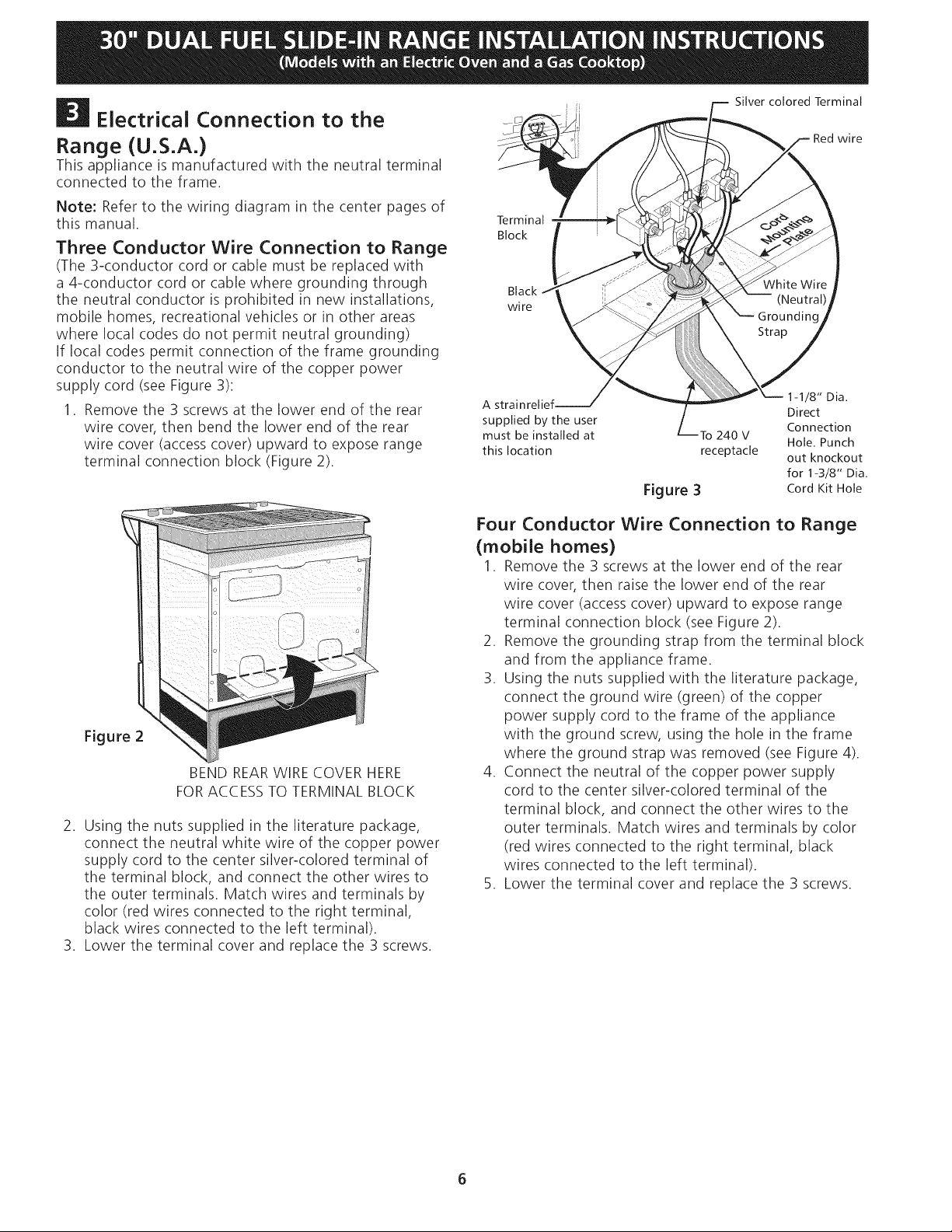
Electrical Connection to the
Range (U.S.A.)
This appliance is manufactured with the neutral terminal
connected to the frame.
Note: Refer to the wiring diagram in the center pages of
this manual.
Three Conductor Wire Connection to Range
(The 3-conductor cord or cable must be replaced with
a 4-conductor cord or cable where grounding through
the neutral conductor is prohibited in new installations,
mobile homes, recreational vehicles or in other areas
where local codes do not permit neutral grounding)
If local codes permit connection of the frame grounding
conductor to the neutral wire of the copper power
supply cord (see Figure 3):
, Remove the 3 screws at the lower end of the rear
wire cover, then bend the lower end of the rear
wire cover (access cover) upward to expose range
terminal connection block (Figure 2).
Figure 2
BEND REARWIRE COVER HERE
FORACCESS TO TERMINAL BLOCK
2. Using the nuts supplied in the literature package,
connect the neutral white wire of the copper power
supply cord to the center silver-colored terminal of
the terminal block, and connect the other wires to
the outer terminals. Match wires and terminals by
color (red wires connected to the right terminal,
black wires connected to the left terminal).
3. Lower the terminal cover and replace the 3 screws.
Silver colored Terminal
Red wire
Terminal
Block
Black
wire
A strainrc
supplied by the user
must be installed at
this location
ro 240 V
receptacle
Figure 3
-1/8" Dia.
Direct
Connection
Hole. Punch
out knockout
for 1-3/8" Dia.
Cord Kit Hole
Four Conductor Wire Connection to Range
(mobile homes)
1. Remove the 3 screws at the lower end of the rear
wire cover, then raise the lower end of the rear
wire cover (access cover) upward to expose range
terminal connection block (see Figure 2).
2. Remove the grounding strap from the terminal block
and from the appliance frame.
3. Using the nuts supplied with the literature package,
connect the ground wire (green) of the copper
power supply cord to the frame of the appliance
with the ground screw, using the hole in the frame
where the ground strap was removed (see Figure 4).
4. Connect the neutral of the copper power supply
cord to the center silver-colored terminal of the
terminal block, and connect the other wires to the
outer terminals. Match wires and terminals by color
(red wires connected to the right terminal, black
wires connected to the left terminal).
5. Lower the terminal cover and replace the 3 screws.
Block
Terminal
White Wire
Cable from
Residence
Wire
1-1/8" Die.
Direct
Connection
Hole. Punch
out knockout
for 1-3/8" Die.
Cord Kit Hole
A strainrelief
supplied by the user /-
must be installed at /To 240 V receptacle
this location
NOTE." Be sure to remove the supplied /_t
grounding strap _"
Figure 4
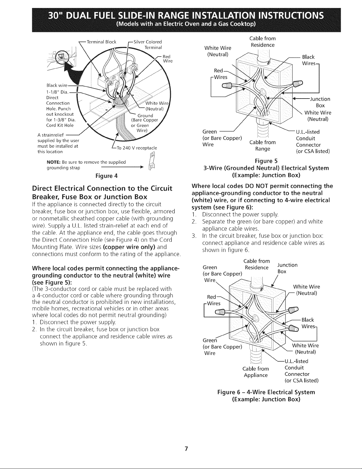
Direct Electrical Connection to the Circuit
Breaker, Fuse Box or Junction Box
If the appliance is connected directly to the circuit
breaker, fuse box or junction box, use flexible, armored
or nonmetallic sheathed copper cable (with grounding
wire). Supply a U.L. listed strain-relief at each end of
the cable. At the appliance end, the cable goes through
the Direct Connection Hole (see Figure 4) on the Cord
Mounting Plate. Wire sizes (copper wire only) and
connections must conform to the rating of the appliance.
Where local codes permit connecting the appliance-
grounding conductor to the neutral (white) wire
(see Figure 5):
(The 3-conductor cord or cable must be replaced with
a 4-conductor cord or cable where grounding through
the neutral conductor is prohibited in new installations,
mobile homes, recreational vehicles or in other areas
where local codes do not permit neutral grounding)
1. Disconnect the power supply.
2. In the circuit breaker, fuse box or junction box
connect the appliance and residence cable wires as
shown in figure 5.
(Neutral) " _,_, ---d_
/_ Black
_idres I :::::_/::::ii_i{:/-_
,,. 14-----Junction
-",_ Box
I \ White Wire
/ (Neutral)
Green __;_
(or Bare Copper) ......
Wire
Cablefrom Connector
_ U.L.-listed
Conduit
Range (or CSAlisted)
Figure 5
3-Wire (Grounded Neutral) Electrical System
(Example: Junction Box)
Where local codes DO NOT permit connecting the
appliance-grounding conductor to the neutral
(white) wire, or if connecting to 4-wire electrical
system (see Figure 6):
1. Disconnect the power supply.
2. Separate the green (or bare copper) and white
appliance cable wires.
3. In the circuit breaker, fuse box or junction box:
connect appliance and residence cable wires as
shown in figure 6.
Cable from
Green Residence Junction
(or Bare Copper) Box
Wire
White Wire
(Neutral)
Green
(or Bare Copper)
Wire
Cable from
Appliance
White Wire
(Neutral)
U.L.-listed
Conduit
Connector
(or CSA listed)
Figure 6 - 4-Wire Electrical System
(Example: Junction Box)
7
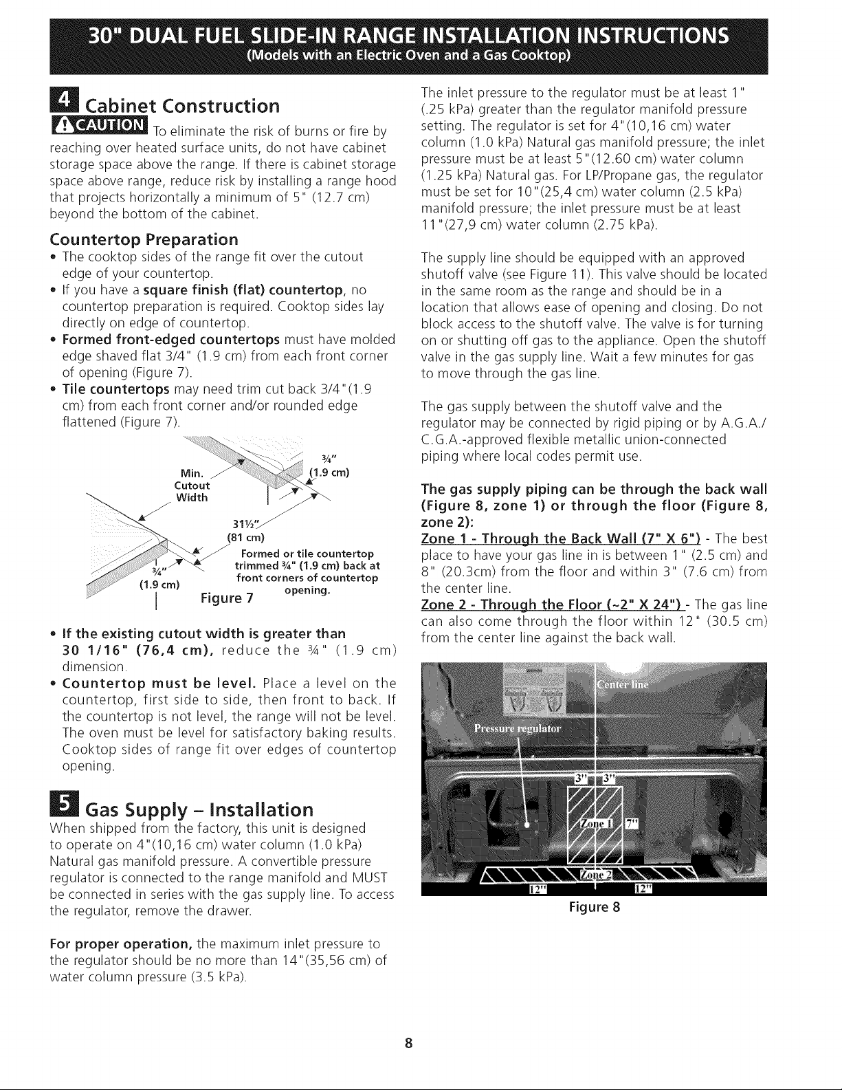
Cabinet Construction
To eliminate the risk of burns or fire by
reaching over heated surface units, do not have cabinet
storage space above the range. If there is cabinet storage
space above range, reduce risk by installing a range hood
that projects horizontally a minimum of 5" (12.7 cm)
beyond the bottom of the cabinet.
Countertop Preparation
• The cooktop sides of the range fit over the cutout
edge of your countertop.
• If you have a square finish (flat) countertop, no
countertop preparation is required. Cooktop sides lay
directly on edge of countertop.
Formed front-edged countertops must have molded
edge shaved flat 3/4" (1.9 cm) from each front corner
of opening (Figure 7).
Tile countertops may need trim cut back 3/4"(1.9
cm) from each front corner and/or rounded edge
flattened (Figure 7).
311/2"_
(81cm)
Formed or tile countertop
trimmed %" (1.9 cm) back at
(1.9 cm)
I
• If the existing cutout width is greater than
30 1/16" (76,4 cm), reduce the 3A" (1.9 cm)
dimension.
Countertop must be level, Place a level on the
countertop, first side to side, then front to back. If
the countertop is not level, the range will not be level.
The oven must be level for satisfactory baking results.
Cooktop sides of range fit over edges of countertop
opening.
front corners of countertop
Figure 7 opening.
The inlet pressure to the regulator must be at least 1"
(.25 kPa) greater than the regulator manifold pressure
setting. The regulator is set for 4"(10,16 cm) water
column (1.0 kPa) Natural gas manifold pressure; the inlet
pressure must be at least 5"(12.60 cm) water column
(1.25 kPa) Natural gas. For LP/Propane gas, the regulator
must be set for 10"(25,4 cm) water column (2.5 kPa)
manifold pressure; the inlet pressure must be at least
11 "(27,9 cm) water column (2.75 kPa).
The supply line should be equipped with an approved
shutoff valve (see Figure 11). This valve should be located
in the same room as the range and should be in a
location that allows ease of opening and closing. Do not
block access to the shutoff valve. The valve is for turning
on or shutting off gas to the appliance. Open the shutoff
valve in the gas supply line. Wait a few minutes for gas
to move through the gas line.
The gas supply between the shutoff valve and the
regulator may be connected by rigid piping or by A.G.A./
C.G.A.-approved flexible metallic union-connected
piping where local codes permit use.
The gas supply piping can be through the back wall
(Figure 8, zone 1) or through the floor (Figure 8,
zone 2):
Zone I - Through the Back Wall (7" X 6") - The best
place to have your gas line in is between 1" (2.5 cm) and
8" (20.3cm) from the floor and within 3" (7.6 cm) from
the center line.
Zone 2 - Through the Floor (~2" X 24") - The gas line
can also come through the floor within 12" (30.5 cm)
from the center line against the back wall.
Gas Supply -Installation
When shipped from the factory, this unit is designed
to operate on 4"(10,16 cm) water column (1.0 kPa)
Natural gas manifold pressure. A convertible pressure
regulator is connected to the range manifold and MUST
be connected in series with the gas supply line. To access
the regulator, remove the drawer.
For proper operation, the maximum inlet pressure to
the regulator should be no more than 14"(35,56 cm) of
water column pressure (3.5 kPa).
Figure 8
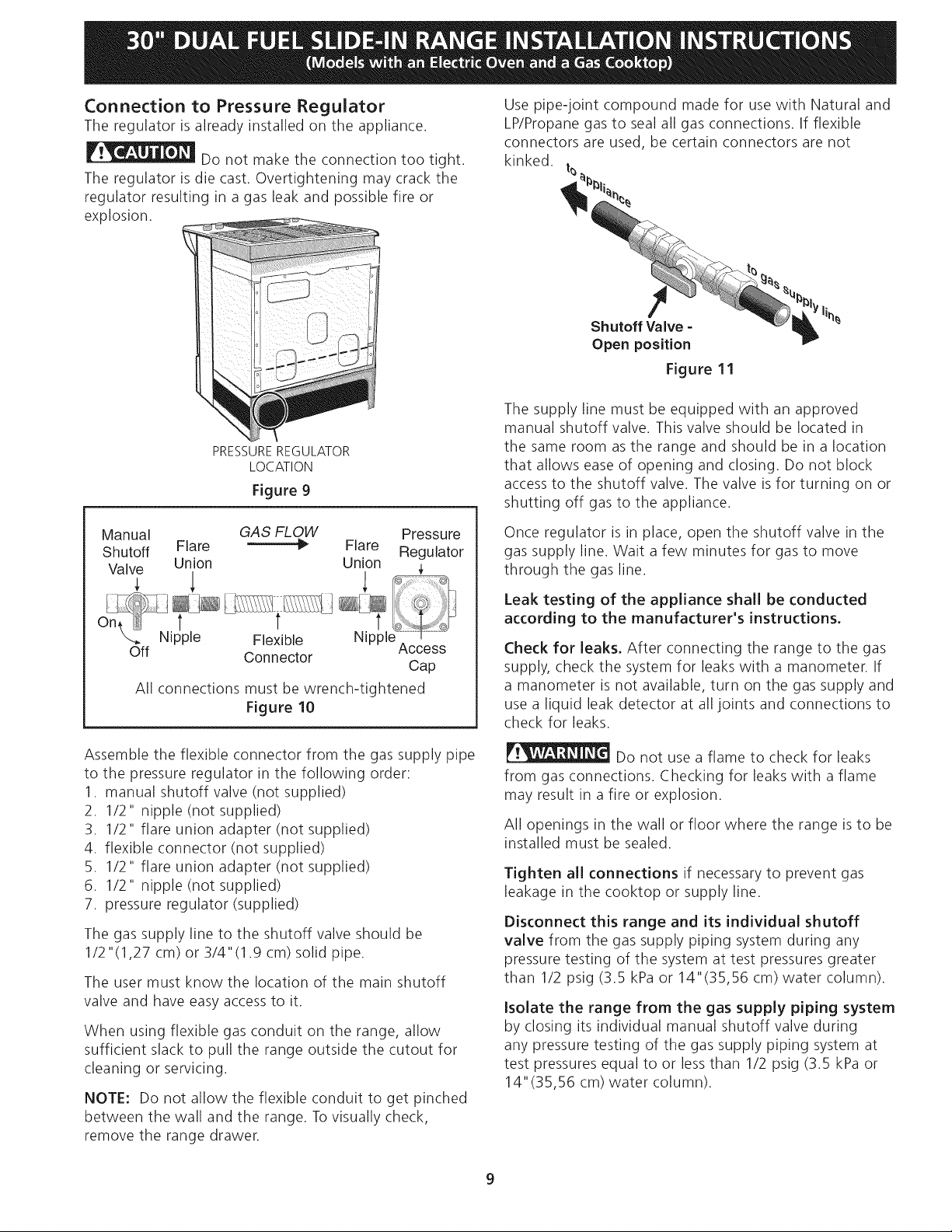
Connection to Pressure Regulator
Theregulatorisalreadyinstalledontheappliance.
Donotmaketheconnectiontootight.
Theregulatorisdiecast.Overtighteningmaycrackthe
regulatorresultinginagasleakandpossiblefireor
explosion.
PRESSUREREGULATOR
LOCATION
Figure 9
Usepipe-jointcompoundmadeforusewithNaturaland
LP/Propanegastosealallgasconnections.Ifflexible
connectorsareused,becertainconnectorsarenot
kinked.
The supply line must be equipped with an approved
manual shutoff valve. This valve should be located in
the same room as the range and should be in a location
that allows ease of opening and closing. Do not block
access to the shutoff valve. The valve isfor turning on or
shutting off gas to the appliance.
t_
Shutoff Valve -
Open position
Figure 11
Manual GAS FLOW Pressure
Shutoff Flare __ Flare Regulator
Valve Union Union
Off Connector
All connections must be wrench-tightened
Figure 10
Assemble the flexible connector from the gas supply pipe
to the pressure regulator in the following order:
1. manual shutoff valve (not supplied)
2. 1/2" nipple (not supplied)
3. 1/2" flare union adapter (not supplied)
4. flexible connector (not supplied)
5. 1/2" flare union adapter (not supplied)
6. 1/2" nipple (not supplied)
7. pressure regulator (supplied)
The gas supply line to the shutoff valve should be
1/2"(1,27 cm) or 3/4"(1.9 cm) solid pipe.
The user must know the location of the main shutoff
valve and have easy access to it.
When using flexible gas conduit on the range, allow
sufficient slack to pull the range outside the cutout for
cleaning or servicing.
NOTE: Do not allow the flexible conduit to get pinched
between the wall and the range. To visually check,
remove the range drawer.
Access
Cap
Once regulator is in place, open the shutoff valve in the
gas supply line. Wait a few minutes for gas to move
through the gas line.
Leak testing of the appliance shall be conducted
according to the manufacturer's instructions.
Check for leaks. After connecting the range to the gas
supply, check the system for leaks with a manometer. If
a manometer is not available, turn on the gas supply and
use a liquid leak detector at all joints and connections to
check for leaks.
Do not use a flame to check for leaks
from gas connections. Checking for leaks with a flame
may result in a fire or explosion.
All openings in the wall or floor where the range is to be
installed must be sealed.
Tighten all connections if necessary to prevent gas
leakage in the cooktop or supply line.
Disconnect this range and its individual shutoff
valve from the gas supply piping system during any
pressure testing of the system at test pressures greater
than 1/2 psig (3.5 kPa or 14"(35,56 cm) water column).
Isolate the range from the gas supply piping system
by closing its individual manual shutoff valve during
any pressure testing of the gas supply piping system at
test pressures equal to or less than 1/2 psig (3.5 kPa or
14"(35,56 cm) water column).
9
LP/Propane Gas Conversion
This appliance can be used with Natural gas or LP/
Propane gas. It is shipped from the factory for use with
natural gas.
If you wish to convert your range for use with LP/
Propane gas, use the supplied fixed orifices located in a
bag containing the literature marked "FOR LP/PROPANE
GAS CONVERSION." Follow the instructions packaged
with the orifices.
The conversion must be performed by a qualified service
technician in accordance with the manufacturer's
instructions and all local codes and requirements. Failure
to follow these instructions could result in serious injury
or property damage. The qualified agency performing
this work assumes responsibility for the conversion.
Failure to make the appropriate
conversion can result in personal injury and property
damage.
Moving the Appliance for
Servicing and Cleaning
Turn off the range line fuse or circuit breakers at the
main power source, and turn off the manual gas shut-off
valve. Make sure the range is cold. Remove the service
drawer (warmer drawer on some models) and open the
oven door. Lift the range at the front and slide it out
of the cut-out opening without creating undue strain
on the flexible gas conduit. Make sure not to pinch
the flexible gas conduit at the back of the range when
replacing the unit into the cut-out opening. Replace
the drawer, close the door and switch on the electrical
power and gas to the range.
Make sure the two front leveling legs and the rear
leveling wheels (see page 11) are setup higher than
the height of the cabinet (shown on page 3).
Remove and discard the two rear leveling legs,
they are only in place to solidify the unit for the
transport.
Install the anti-tip bracket at
this point before placing the range at its final
position. Follow the installation instructions on
page 14 or on the anti-tip bracket template supplied
with the range.
To provide an optimum installation, the top surface
of the countertop must be level and flat (lie on the
same plane) around the 3 sides that are adjacent
to range cooktop. Proper adjustments to make
the top flat should be made or gaps between the
countertop and the range cooktop may occur.
__ To reduce the risk of damaging your
appliance, do not handle or manipulate it by the
cooktop. Manipulate with care.
O Position range in front of the cabinet opening.
O Make sure that the underside of the cooktop
clears the countertop. If necessary, raise the unit
by lowering the front leveling legs and the back
leveling wheels.
_11 Level the range (see section 9). The floor where
the range is to be installed must be level. Follow the
instructions under "Leveling the Range".
_ Slide the range into the cutout opening.
If Accessories Needed :
| Range Installation
Important Note: Door removal is not a requirement for
installation of the range, but is an added convenience.
Refer to the Use and Care Guide for oven door removal
instructions.
Standard Installation
_The range cooktop overlaps the countertop at the
sides and the range rests on the floor. The cooktop
is 311/2'` (80 cm) wide.
O
Install base cabinets 30" (76.2 cm) apart. Make sure
they are plumb and level before attaching cooktop.
Shave raised countertop edge to clear 311/2" (80
cm) wide range top rim.
Install cabinet doors 32" (81.3 cm) min. apart so as
not to interfere with range door opening.
Cutout countertop exactly as shown on page 1.
Installation With Backguard
The cutout depth of (21 3/4" (55.2 cm)Min., 22 1/8"
(56.2cm) Max.) needs to be increased to 24" (61 cm)
when installing a backguard.
Installation With End Panel
A End Panel kit can be ordered through a Service
Center.
Installation With Side Panels
A Side Panels kit can be ordered through a Service
Center.
Install cabinet doors 32" (81.3 cm) min. apart so as
not to interfere with range door opening.
10
Leveling the Range
Models Equipped with Leveling Device
Level the range after installation in the cutout
opening.
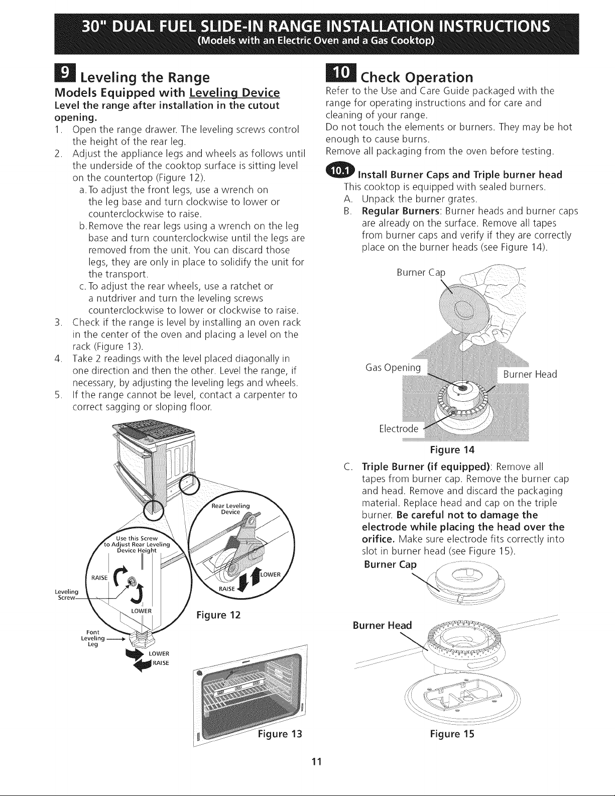
1. Open the range drawer. The leveling screws control
the height of the rear leg.
2. Adjust the appliance legs and wheels as follows until
the underside of the cooktop surface is sitting level
on the countertop (Figure 12).
a.To adjust the front legs, use a wrench on
the leg base and turn clockwise to lower or
counterclockwise to raise.
b.Remove the rear legs using a wrench on the leg
base and turn counterclockwise until the legs are
removed from the unit. You can discard those
legs, they are only in place to solidify the unit for
the transport.
c. Toadjust the rear wheels, use a ratchet or
a nutdriver and turn the leveling screws
counterclockwise to lower or clockwise to raise.
3. Check if the range is level by installing an oven rack
in the center of the oven and placing a level on the
rack (Figure 13).
4. Take 2 readings with the level placed diagonally in
one direction and then the other. Levelthe range, if
necessary, by adjusting the leveling legs and wheels.
5. If the range cannot be level, contact a carpenter to
correct sagging or sloping floor.
Check Operation
Refer to the Use and Care Guide packaged with the
range for operating instructions and for care and
cleaning of your range.
Do not touch the elements or burners. They may be hot
enough to cause burns.
Remove all packaging from the oven before testing.
Install Burner Caps and Triple burner head
This cooktop is equipped with sealed burners.
A. Unpack the burner grates.
B. Regular Burners: Burner heads and burner caps
are already on the surface. Remove all tapes
from burner caps and verify if they are correctly
place on the burner heads (see Figure 14).
Burner Cap
GasOpening
Burner Head
Leveling
Font
Leveling
Leg
LOWER
RAISE
Figure 12
Electrode
Figure 14
C,
Triple Burner (if equipped): Remove all
tapes from burner cap. Remove the burner cap
and head. Remove and discard the packaging
material. Replace head and cap on the triple
burner. Be careful not to damage the
electrode while placing the head over the
orifice. Make sure electrode fits correctly into
slot in burner head (see Figure 15).
Burner Cap / .......... _ .....
Burner Head
.... J
11
Figure 15Figure 13
D. Besurethatalltheburnercapsandthetriple
burnerheadarecorrectlyplacedBEFOREusing
yourcooktop.
NOTE:Therearenoburneradjustmentsnecessaryon
thiscooktop.
O Turnon ElectricalPowerandOpenMain
ShutoffGas Valve
Check the Igniters
Operation of electric igniters should be checked after
range and supply line connectors have been carefully
checked for leaks and range has been connected to
electric power. To check for proper lighting:
1.Push in and turn a surface burner knob to the LITE
position. You will hear the igniter sparking.
2. The surface burner should light when gas is available
to the top burner. Each burner should light within
four (4) seconds in normal operation after air has been
purged from supply lines. Visually check that burner
has lit.
3.Once the burner lights, the control knob should be
rotated out of the LITEposition.
There are separate ignition devices for each burner. Try
each knob separately until all burner valves have been
checked.
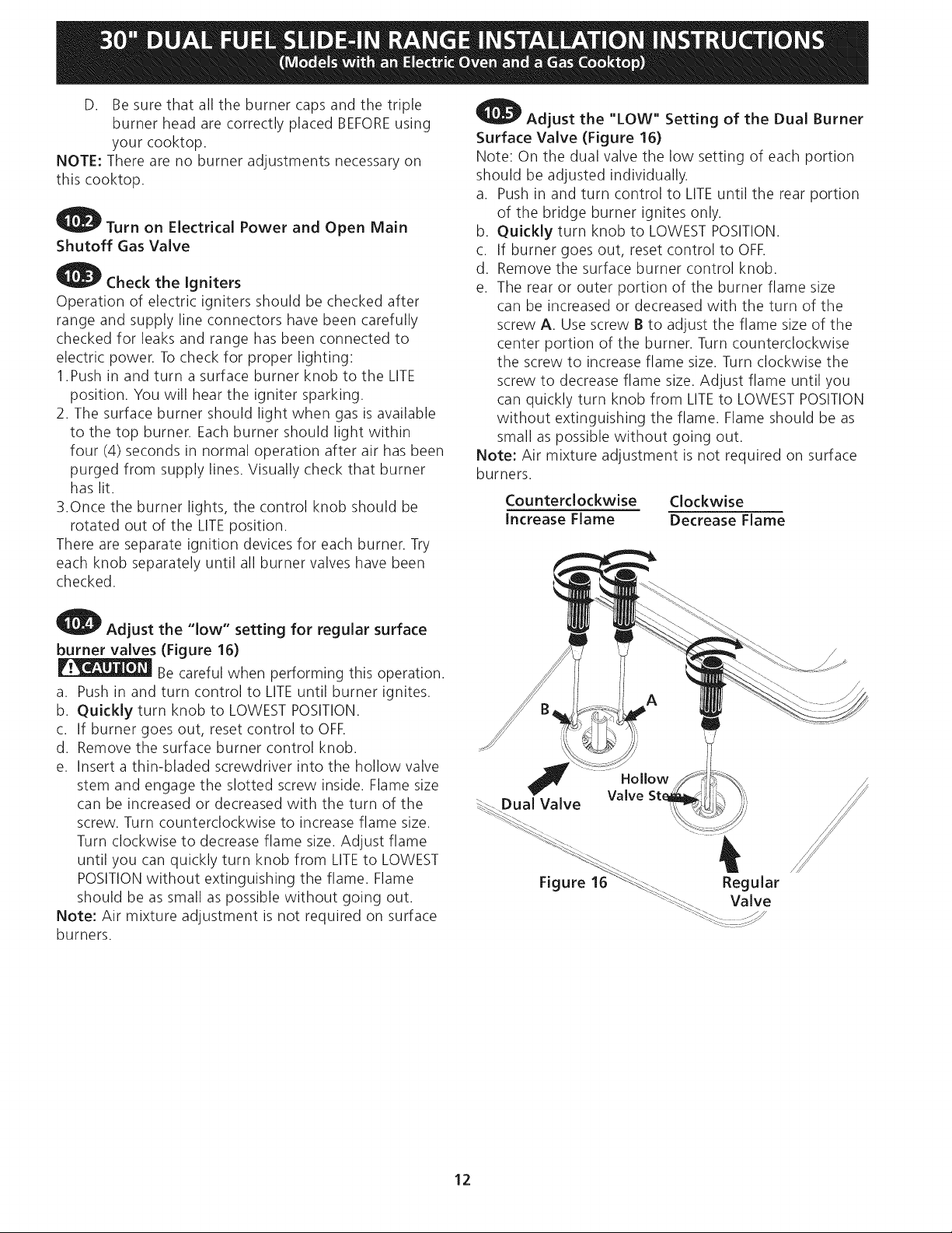
O Adjust the ""LOW""Setting of the Dual Burner
Surface Valve (Figure 16)
Note: On the dual valve the low setting of each portion
should be adjusted individually.
a. Push in and turn control to LITEuntil the rear portion
of the bridge burner ignites only.
b. Quickly turn knob to LOWEST POSITION.
c. If burner goes out, reset control to OFF.
d. Remove the surface burner control knob.
e. The rear or outer portion of the burner flame size
can be increased or decreased with the turn of the
screw A. Use screw B to adjust the flame size of the
center portion of the burner. Turn counterclockwise
the screw to increase flame size. Turn clockwise the
screw to decrease flame size. Adjust flame until you
can quickly turn knob from LITEto LOWESTPOSITION
without extinguishing the flame. Flame should be as
small as possible without going out.
Note: Air mixture adjustment is not required on surface
burners.
Counterclockwise
increase Flame
Clockwise
Decrease Flame
_ Adjust the "low" setting for regular surface
burner valves (Figure 16)
Be careful when performing this operation.
a. Push in and turn control to LITEuntil burner ignites.
b. Quickly turn knob to LOWEST POSITION.
c. If burner goes out, reset control to OFF.
d. Remove the surface burner control knob.
e. Insert a thin-bladed screwdriver into the hollow valve
stem and engage the slotted screw inside. Flame size
can be increased or decreased with the turn of the
screw. Turn counterclockwise to increase flame size.
Turn clockwise to decrease flame size. Adjust flame
until you can quickly turn knob from LITEto LOWEST
POSITIONwithout extinguishing the flame. Flame
should be as small as possible without going out.
Note: Air mixture adjustment is not required on surface
burners.
12
O Operationof OvenElements
Theovenisequippedwithanelectronicovencontrol.Each
ofthefunctionshasbeenfactorycheckedbeforeshipping.
However,itissuggestedthatyouverifytheoperation
oftheelectronicovencontrolsoncemore.Refertothe
ElectronicOvenControlGuideforoperation.Followthe
instructionsfortheClock,Timer,Bake,Broil,Convection
(somemodels)andCleanfunctions.
Bake-Aftersettingtheovento350°F(177°C)for
baking,thelowerelementintheovenshouldbecome
red.
Broil-WhentheovenissettoBROIL,theupperelement
intheovenshouldbecomered.
Clean-Whentheovenissetforaself-cleaningcycle,the
upperelementshouldbecomeredduringthepreheat
portionofthecycle.
Convection(somemodels)-Whentheovenissetto
CONV.BAKE/ROASTat350°F(177°C),theconvection
elementcyclesonandoff andtheconvectionfanturns.
Theconvectionfanwillstopturningwhentheovendoor
isopenedduringconvectionbakingorroasting.
WarmerDrawer(somemodels)-Setthecontrolknob
toHIandcheckto seethedrawerisheating.
When All Hookups are Complete
MakesureallcontrolsareleftontheOFFposition.
Makesuretheflowofcombustionandventilationairtothe
rangeisunobstructed.
Model and Serial Number Location
The serial plate is located on the oven front frame behind
the oven door (some models) or on the drawer side frame
(some models).
When ordering parts for or making inquiries about your
range, always be sure to include the model and serial
numbers and a lot number or letter from the serial plate
on your range.
Your serial plate also tells you the rating of the burners,
the type of fuel and the pressure the range was adjusted
for when it left the factory.
Before You Call for Service
Read the Avoid Service Checklist and operating
instructions in your Use and Care Guide. It may save you
time and expense. The list includes common occurrences
that are not the result of defective workmanship or
materials in this appliance.
Refer to the warranty and service information in your
Use and Care Guide for phone number and address.
Please call or write if you have inquiries about your range
product and/or need to order parts.
13
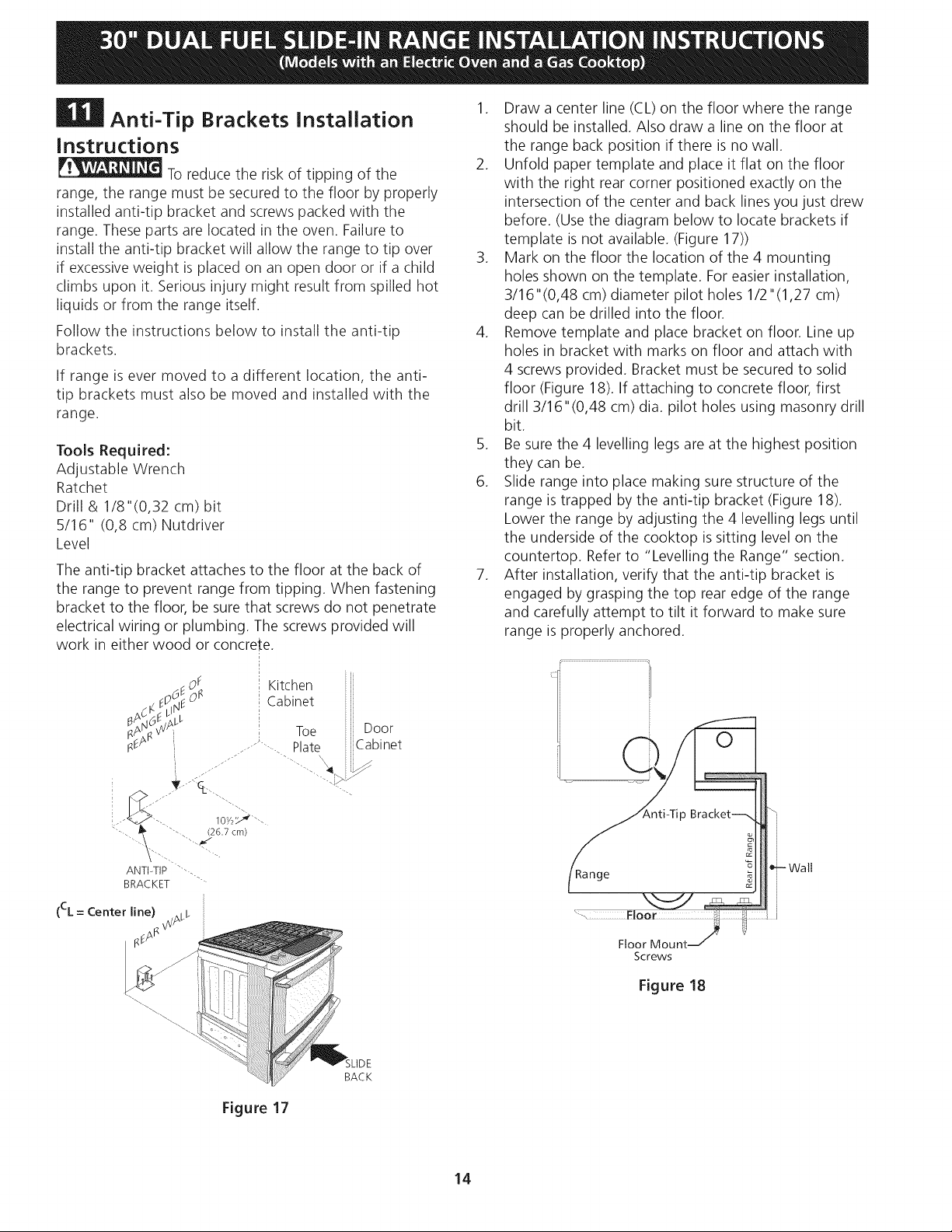
Anti-Tip Brackets Installation
instructions
To reduce the risk of tipping of the
range, the range must be secured to the floor by properly
installed anti-tip bracket and screws packed with the
range. These parts are located in the oven. Failureto
install the anti-tip bracket will allow the range to tip over
if excessiveweight is placed on an open door or if achild
climbs upon it. Serious injury might result from spilled hot
liquids or from the range itself.
Follow the instructions below to install the anti-tip
brackets.
If range is ever moved to a different location, the anti-
tip brackets must also be moved and installed with the
range.
Tools Required:
Adjustable Wrench
Ratchet
Drill & 1/8"(0,32 cm) bit
5/16" (0,8 cm) Nutdriver
Level
The anti-tip bracket attaches to the floor at the back of
the range to prevent range from tipping. When fastening
bracket to the floor, be sure that screws do not penetrate
electrical wiring or plumbing. The screws provided will
work in either wood or concrete.
1. Draw a center line (CL)on the floor where the range
should be installed. Also draw a line on the floor at
the range back position if there is no wall.
2. Unfold paper template and place it flat on the floor
with the right rear corner positioned exactly on the
intersection of the center and back lines you just drew
before. (Use the diagram below to locate brackets if
template is not available. (Figure 17))
3. Mark on the floor the location of the 4 mounting
holes shown on the template. For easier installation,
3/16"(0,48 cm) diameter pilot holes 1/2"(1,27 cm)
deep can be drilled into the floor.
4. Remove template and place bracket on floor. Line up
holes in bracket with marks on floor and attach with
4 screws provided. Bracket must be secured to solid
floor (Figure 18). If attaching to concrete floor, first
drill 3/16" (0,48 cm) dia. pilot holes using masonry drill
bit.
5. Be sure the 4 levelling legs are at the highest position
they can be.
6. Slide range into place making sure structure of the
range is trapped by the anti-tip bracket (Figure 18).
Lower the range by adjusting the 4 levelling legs until
the underside of the cooktop is sitting level on the
countertop. Refer to "Levelling the Range" section.
7. After installation, verify that the anti-tip bracket is
engaged by grasping the top rear edge of the range
and carefully attempt to tilt it forward to make sure
range is properly anchored.
_jG .,ALL
(CL = Center line) _d.
of
i Kitchen
i Cabinet
Toe i Door
...........Plate iCabinet
Screws
Figure 18
BACK
Figure 17
14
 Loading...