

Page 1
Cooktop
OPERAOPERA
OPERAOPERA
OPERA
TING INSTRTING INSTR
TING INSTRTING INSTR
TING INSTR
UCTIONSUCTIONS
UCTIONSUCTIONS
UCTIONS
Model EHM 9780
35686-3803
SA
Page 2

2
Installation
● Appliance installation and connection to the power sup-
ply must only be carried out by QUALIFIED PERSONNEL.
Before carrying out any operation, make sure the appliance is DISCONNECTED from the power supply.
● Make sure air can circulate freely around the appliance.
Poor ventilation creates a lack of oxygen.
● Make sure the appliance is fed with the type of gas
specified on the special sticker located near the gas
connection pipe.
● The use of a gas cooking appliance produces heat and
humidity in the room where it is installed. Ensure good
ventilation in the room by keeping air inlets open and
efficient, or install an extractor hood with exhaust flue.
● In case of intensive and prolonged appliance use, room
ventilation must be made more efficient by opening a
window or increasing the power of the electric exhaust
fan, if present.
● After unpacking the appliance, make sure it is not dam-
aged and that the power cable is in perfect condition.
Otherwise, contact the dealer before using the appliance.
● The Manufacturer declines any liability if the accident-
prevention regulations are not respected.
During operation
● This appliance must only be used by adults. Make sure
children do not play with the appliance or touch the
controls.
● This product is designed for non-professional home use,
for cooking food.
Do not use it for any other purpose.
● Modifying or attempting to change the characteristics of
this product is hazardous.
● Keep the appliance clean. Food residuals can create the
risk of fire.
● The exposed parts of this appliance become hot during
cooking and remain hot for a certain amount of time even
after the appliance is turned off. Keep children away until
it has cooled.
● In case of faults, never try to repair the appliance on your
own. Repairs carried out by unqualified persons can
cause damage and accidents. Firstly, consult this handbook. If you do not find the necessary information, contact
the nearest Assistance Centre. Assistance for this appliance must be carried out by an authorised Technical
Assistance Centre. Always demand the use of original
spare parts.
For your safety
● After using the appliance, make sure all the controls are
in the “CLOSED” or “OFF” position.
● When using a power socket near this appliance, make
sure the cords of any electrical appliances being used do
not touch it and are far enough away from its hot parts.
Advice for safeguarding
the environment
● All the materials used are environmentally friendly and
recyclable. Please make your contribution to safeguarding the environment by using the special differentiated
waste collection channels.
Appliances in disuse
● Appliances that are no longer used or unusable are not
worthless waste. Through ecological disposal, various
materials used in manufacturing your appliance can be
recovered.
● Find out about the possibilities of disposal from your
specialised dealer or local Council.
● When disposing of the appliance, make it unusable by
cutting off the power cable.
● The symbol on the product or on the packing
indicates that it should not be treated as normal household waste but must be taken to an appropriate collection point for the recycling of electrical and electronic
equipment. Correct disposal of this appliance will help
prevent possible negative consequences for the environment and the health of persons.
For more detailed information about the recycling of
this product, contact your local council office or waste
disposal service, or the shop where you purchased
the product.
This new appliance is easy to use,
however, make sure to read this handbook before installing and using it for the first time. In this way you can obtain
best use, avoid incorrect operations, use the appliance in complete safety and respect the environment.
Page 3
3
Content s
Operating
instructions
Before using the appliance, remove all the
packing materials, including advertising
labels and any protective films.
Cooktop
control knobs
The knobs for the gas rings are located on the front part
of the top. The symbols on the knobs have the following
meaning:
● no gas
max. gas
min. gas
Lighting the rings
To obtain the flame more easily, light the ring
before placing a recipient on the grate.
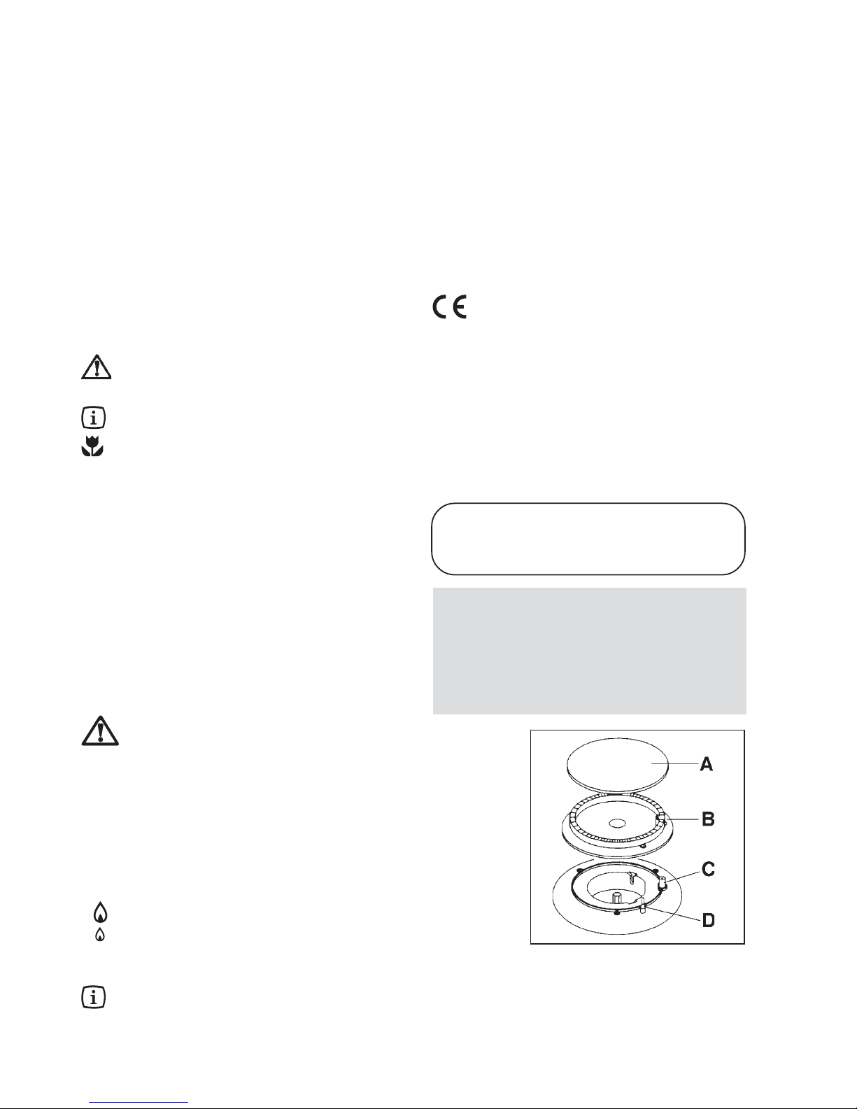
Fig. 1
A - Cap
B - Flame spreader
C - Igniter plug
D - Thermocouple (models without
igniter pushbutton)
MANUFACTURER:
ELECTROLUX HOME PRODUCTS ITALY S.p.A.
Viale Bologna 298
47100 FORLI’ (Italy)
Instruction guide
The following symbols will help you quickly find the
main information.
Safety instructions
Step by step instructions
Useful advice and suggestions
Information on protecting the environment
For the user
For the installer
For your safety 2
Operating instructions 3
Cleaning and maintenance 5
Periodical maintenance 6
Assistance and spare parts 6
Technical specifications 6
Instructions for the installer 7
Electrical connection 7
Conversion to other types of gas 9
Fitting on modular cabinets 10
This appliance complies with the following EEC
Directives:
-73/23 and 90/683 (Low Voltage);
-89/336
(Electromagnetic Compatibility);
-90/396 (Gas Appliances)
-93/68 (General Standards)
and subsequent amendments.
This instruction handbook must be kept with the
appliance for any future consultation. If the
appliance is sold or given to another person, make
sure the handbook goes with it, so that the new
user can know how to use the appliance with the
relevant instructions.
These instructions are only valid for countries
whose identification symbols appear on the
handbook cover and on the appliance.
Page 4
4
Also, as soon as a liquid starts to boil, lower the flame enough
to keep it on the boil.
For correct use of the rings
To ensure lower gas consumption and better efficiency, only
use flat bottom recipients of suitable size for the rings, as
given in the table.
Burner min max
diameter diameter
Large (rapid) 180 mm 260 mm
Medium (semirapid) 120 mm 220 mm
Small (auxiliary) 80 mm 160 mm
The cooktop lid
(only for tops with enamelled iron grates)
In order to obtain an aesthetic alignment with the kitchen
cabinets, the top is arranged for fitting a lid, supplied by
request.
● The lid serves to protect the top from dust, when
closed, and collecting splashes of grease, when
open. DO NOT use it for any other purpose.
● Before opening the lid, dry off any traces of
liquids.
● Clean any cooking residuals from the lid before
closing or removing it.
● IMPORT ANT! The glass top may splinter if over-
heated. Make sure all the rings are turned off
before closing it.
Broiler
The top has an electric broiler located in the middle of the
cooktop.
The knob has 8 different settings, from “0” (broiler off) to
“max” (maximum setting).
The broiler may create smoke or unpleasant odours
when used for the first time. This inconvenience will
disappear after a few minutes’ operation.
It is always advisable to preheat the broiler at max. setting
for not more than 15 minutes, and then turn the knob to the
required setting.
Food Quantity No. Temperature Preheat Cooking time (minutes)
in g. pieces setting in minutes
top side bottom side
Sausages 500 approx. 6 4 15 8-10 6-8
Pork
chops 400 approx. 4 6 10 5-6 5-6
Bacon 400 approx. 4 4 15 4-5 4-5
Aubergines - - 6 10 6-7 5-6
Capsicums - - 6 1 0 7-8 6-7
Courgettes - - 4 10 4-5 3-4
Chicory - - 4 10 4-5 3-4
Polenta 500 - 6 15 8-10 6-8
Fresh bread - 6 slices 6 10 6-7 5-6
Dry bread - 6 slices 6 10 5-6 3-4
Several instructions on using the broiler are given in the
table at the bottom of this page. The levels and times are
given merely by way of example and can be adapted to
personal needs and tastes. For cooking particularly fatty
foods (sausages, bacon, etc.) it is best to use intermediate
settings, to prevent the creation of smoke.
After using the broiler, in particular for lengthy
cooking, the front part stays hot for at least 45
minutes even after switching off. Wear pot-holders
or oven gloves when operating near the surface of
the broiler.
The stainless steel can become tarnished if
excessively heated. Therefore prolonged
cooking with potstones, earthenware pans or
cast-iron plates is inadvisable. Also, do not use
aluminium foil to protect the top during use.
Carefully watch over your food during cooking
with fats or oils, because these substances can
catch fire when very hot.
Page 5
5
Cleaning and maintenance
Before carrying out any operation, disconnect
the appliance from the power supply and
allow it cool
General cleaning
Clean the enamelled parts with lukewarm water and detergent; do not use abrasive products which could damage them.
Clean the flame spreader and caps frequently with boiling water and detergent, making sure to remove all deposits.
After use, rinse the stainless-steel parts thoroughly with
water and dry with a soft cloth.
For stubborn stains, use normal non-abrasive detergents
or specific products, readily available on the market.
DO NOT use scouring pads, steel wool or acids.
Cleaning the electric igniter
Automatic ring lighting is ensured by the presence of a
ceramic igniter plug (Fig. 1, C). Carefully clean this part
of the top periodically . Also, to prevent dif ficulty in lighting, make sure the flame spreader crown holes are not
clogged (B).
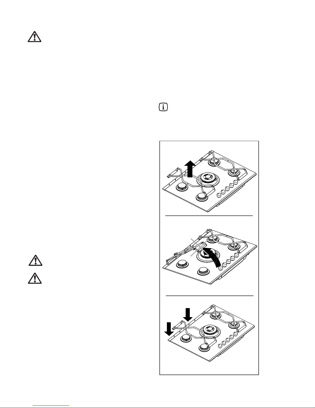
The worktop grates are kept in place by two metal
pins located on the back trim of the cooktop. The
grates can be removed from the cooktop for better
cleaning. Lift the grates, keeping them horizontal as
shown in fig. 2.
Do not tilt the grates by levering on the
pins, as this could damage or break the
pins.
If damage is noted, disconnect the
appliance from the power supply in order
to prevent risk of electric shocks, and call
the nearest Authorised Technical
Assistance Centre.
After washing, make sure the grates are correctly
positioned as shown in fig. 2.
The worktop grates can be placed in a dishwasher.
For stubborn stains, use normal non-abrasive
detergents or specific products, readily available
on the market.
DO NOT use scouring pads, steel wool or acids.
Fig. 2
YES
NO
Chromed caps and grates
Chromed caps and grates tend to darken with use. This
is normal and inevitable, but does does affect cooktop
operation in any way .
Enamelled caps and grates are available by request from your dealer or our Technical Assistance Centres.
Page 6
6
Gas burner power
Rapid burner (large) (G 20) 3.0 kW
Rapid burner (large) (G 30/G31) 2.8 kW
Semirapid burner (medium) 2.0 kW
Auxiliary burner (small) 1.0 kW
Electric broiler power 1.0 kW
Appliance class : 3
Category II2H3+
Appliance setting LPG (G 30/G31) 28-30/37 mbar
Gas inlet connection G 1/2"
Power supply (50 Hz) 230 V
Dimensions of opening for fitting
Width 830 mm
Depth 480 mm
T echnical specifications
Have the state and efficiency of the gas pipe and the
pressure regulator (if present) periodically checked. If
any anomalies are detected, have the faulty part replaced
(and not repaired).
To guarantee correct operation and safety, periodically
grease the gas adjustment cocks.
● Periodical lubrication of the cocks must only be
carried out by QUALIFIED PERSONNEL; contact
only qualified personnel in case of anomalies in
appliance operation.
Periodical
maintenance
Do not use mild detergents (e.g. products f o r
cleaning crockery) which, if not properly rinsed
off, can have a corrosive effect or discolour the
surface of the top.
Do not place materials that could melt, such as
aluminium foil, plastic materials, sugar or food with
high sugar content, on the top.
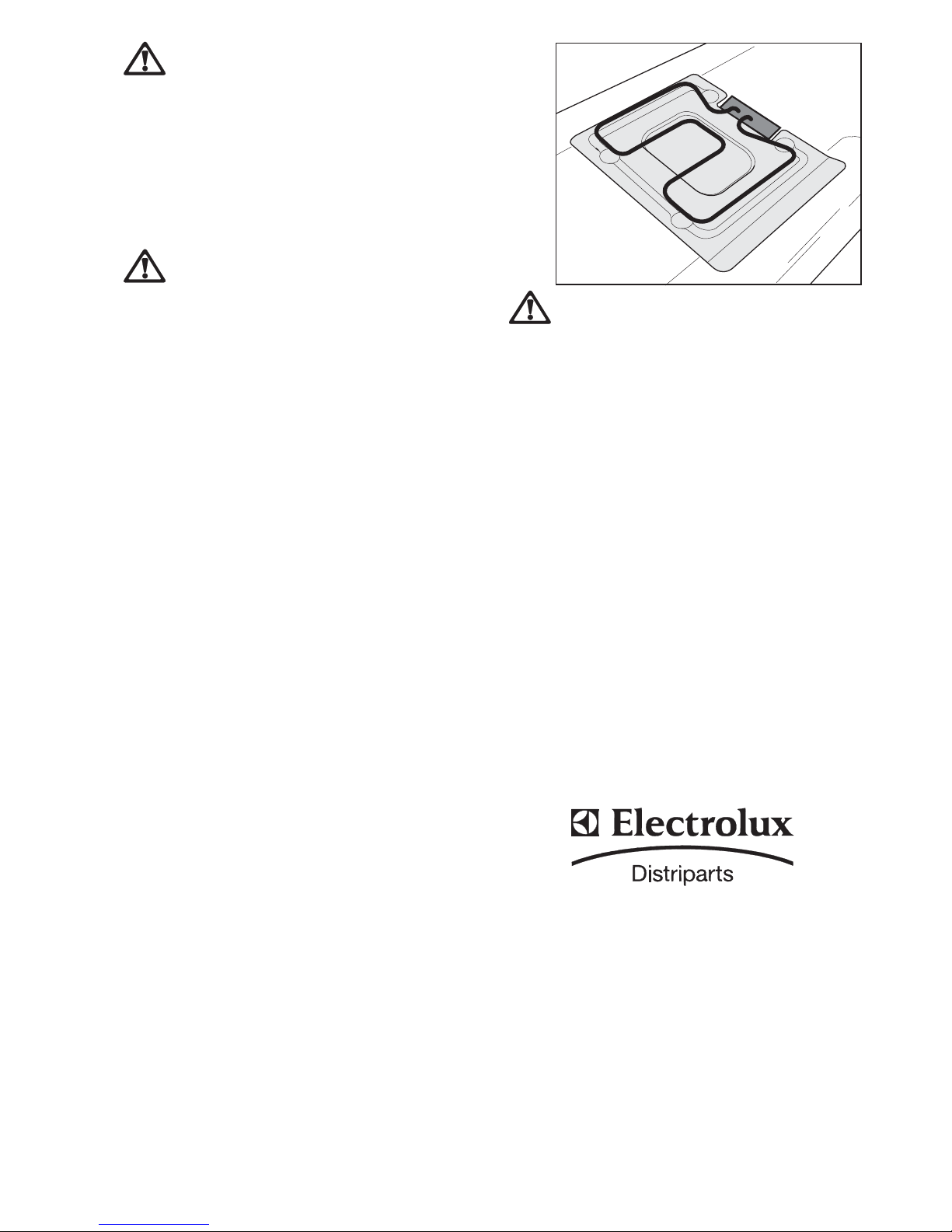
Important! For correct broiler operation,
correctly reposition the screen (see fig. 3).
Electric broiler
Clean the broiler when it is cold, using absorbent paper
or a damp cloth that does not leave strands. Carefully
dry the broiler before using it again. It is advisable to
occasionally go over it with a little cooking oil or paraffin
oil, while it is still warm.
Fig. 3
IMPORTANT! If any of these products melts on
the vitroceramic top, remove it with a scraper (when
the top is still warm). If necessary , complete the
cleaning with a specific product.
Before leaving the factory, the appliances are inspected
and prepared by specialised personnel, in order to
ensure best operating results. Any subsequent repairs
or preparation becoming necessary must be carried out
with maximum care and attention.
Therefore it is advisable to always see your local dealer
or the nearest Assistance Centre, specifying the type of
problem, the appliance model (Mod.), product number
(Prod. No.) and serial number (Ser. No.).
Original spare parts, certified by the product
manufacturer, and identified by this mark, are only
available at our Technical Assistance Centres and
Authorised Spare Parts Shops.
Assist ance and
spare parts
Page 7
7
IMPORTANT: This appliance can only be installed and
used in permanently ventilated places.
● Appliance installation and connection to the power
supply must only be carried out by QUALIFIED
PERSONNEL. Before carrying out any operation,
make sure the appliance is DISCONNECTED from
the power supply.
THE MANUFACTURER DECLINES ANY LIABILITY
FOR POSSIBLE DAMAGE DUE TO INSTALLATION
NOT COMPLYING WITH THE CURRENT
STANDARDS OR FAILURE TO RESPECT THE
ACCIDENT-PREVENTION REGULATIONS.
Instructions for the installer
Gas supply connection
The gas connection must be carried out in compliance
with the current regulations. The appliances leave the factory , tested and adjusted for the type of gas specified on
the plate located in the bottom protection, near the gas
connection pipe. Make sure the type of gas used is the
same as that specified on the plate. Otherwise, proceed
according to the instructions given in the section “Converting to different types of gas”. T o ensure maximum ef ficiency
and lower consumption, make sure the gas supply pressure respects the values given in the “Burner specifications”
table.
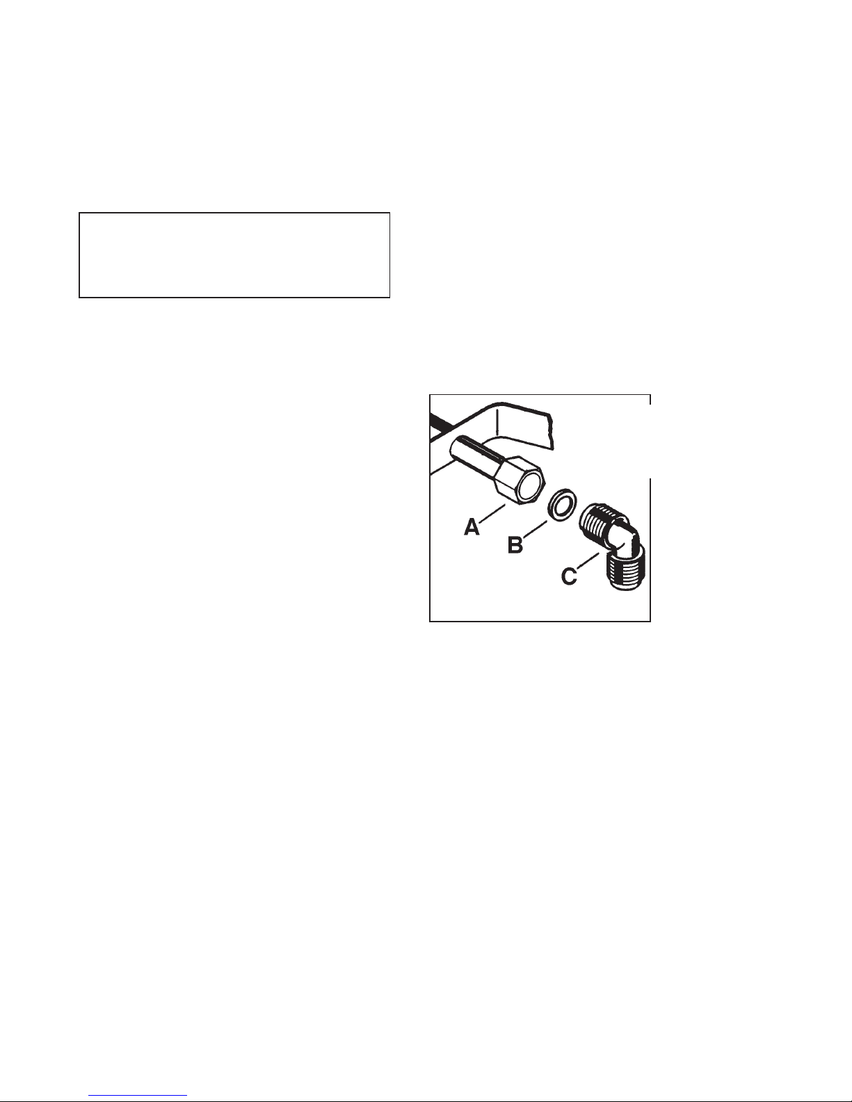
The union is fitted on the end part of the gas train, with a G
1/2" threaded nut, interposing the seal between the components as shown in Fig. 12. Screw the parts without forcing, turn the union in the required direction, then tighten
everything.
Connection
Make the connection to the gas system using a rigid
metal pipe and fittings complying with the current standards, or with a s/steel flexible tube complying with the
current standards, limited to those not longer than 2 m.
When using flexible metal tubes make sure they are not in
contact with movable parts or squashed. Pay the same attention also when an oven and top combination is provided
for. The gas inlet union for the appliances is 1/2" cylindrical
male thread.
Make the connection, avoiding any kind of stress on the
appliance.
● IMPORTANT: After installation, always check the
perfect seal of all unions using a soapy solution.
Never carry out this check with a flame.
A ) Gas train end with nut
B) Seal
C) Adjustable union
Fig. 12
FO 0264
The appliance is arranged to operate on a 230 V singlephase power supply. Connection must be made in
compliance with current standards and regulations.
Before carrying out the connection, make sure:
● the limiter valve and the electrical system can take the
appliance load (refer to the serial no. plate);
● the supply system is equipped with an efficient earth
connection in compliance with current standards;
● the socket or omnipolar switch used are easily
accessible with the appliance installed.
Fit the cable with a plug suitable for the load and connect
it to a suitable safety socket.
To connect directly to the mains, a suitable omnipolar
switch with contact gap of at least 3 mm complying with
Electrical connection
current standards must be installed between the
appliance and the network. The yellow/green earth wire
must not be interrupted by the switch.
The brown phase wire (coming from terminal “L” on the
terminal block) must always be connected to the power
supply phase wire.
In any case the power cable must be positioned in such
a way that no part of it reaches a temperature of more
than 90°C.
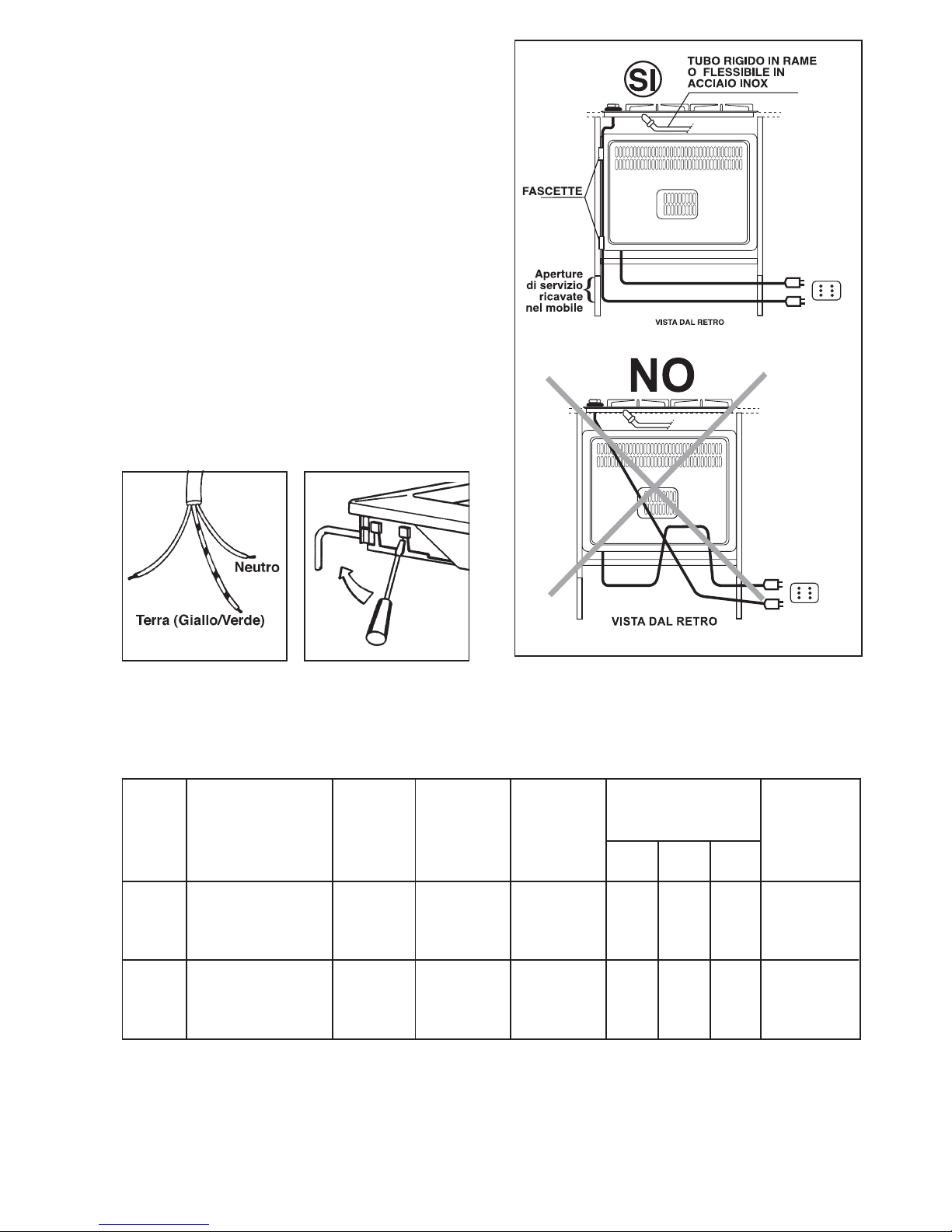
An example of an optimum path is given in Fig. 15. The
cable is guided by means of clamps fixed to the side of
the cabinet, in order to avoid any contact with the
equipment beneath the cooktop.
Page 8
8
Fig. 13
Fig. 14
Replacing the power cable
The power cable connection to the terminal block is of
the “Y” type: the flexible cable can only be replaced with
the use of a special tool that the service technicians
have.
When replacing the power cable only use H05V2V2-F
T90 type cables suitable for the load and operating temperature. Also, the yellow/green earth wire must be
approx. 2 cm longer than the phase and neutral wires
(Fig. 13).
After connection, test the heating elements by operating them for about 3 minutes.
To open the terminal block cover and access the connection terminals, proceed as follows:
● insert the tip of a screwdriver in the protrusions on the
visible side of the terminal block;
● press lightly and prise upwards (Fig. 14).
Fig. 15
TABLE 1 : BURNER SPECIFICATIONS
TYPE NOMINAL REDUCED NOMINAL
FEED
OF GAS BURNERS INJECTORS POWER POWER POWER
PRESSURE
1/100 mm kW kW mbar
m3/h
g/h G30 g/h G31
Rapid 119 3.0 0.65 0.286 - - 20
Semirapid 96 2.0 0.45 0.190 - -
Auxiliary 70 1.0 0.33 0.095 - -
Rapid 86 2.8 0.65 - 203 200 28-30/37
Semirapid 71 2.0 0.45 - 145 143
Auxiliary 50 1.0 0.33 - 72 71
NATURAL
GAS
LPG
(But./
Prop.)
Page 9
9
BY-PASS DIAMETERS
Burner Ø Cock
By-pass
in hundredths
Auxiliary 28
Semirapid 32
Rapid, 4 0
The above adjustment operations can be easily performed,
whatever the positioning or fixing of the cooktop on the
kitchen cabinet.
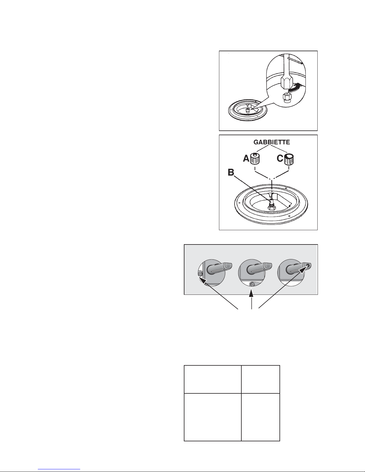
Minimum flame adjustment
T o adjust the minimum flame, proceed as follows.
1. Light the burner as previously described.
2. Turn the cock to the min. flame position.
3. Remove the knobs.
4. Adjust the by-pass pin indicated in fig. 18.
• When converting from natural gas to LPG, screw down
the by-pass pin clockwise. When converting from natural
gas to town gas, unscrew it 3/4 turn (approx.).
• In any case, the result must be a small and even flame
on all the burner crown.
5. Lastly, check that the burner does not go off when
quickly turning the cock from max. to min.
Replacing nozzles
1. Remove the grates.
2. Remove the burner caps and flame spreaders.
3. Using a 7 mm socket wrench, unscrew and remove
(Fig. 16) the nozzles, replacing them with those
required for the type of gas used (refer to table 1 on the
previous page).
T o adapt the nozzles for operation on T own gas, after
fitting the special types (fig. 17, B) screw the special
cages on to them: for the semirapid and auxiliary
burners use the cage indicated by letter A (with Ø 10
hole), and the cage indicated by letter C (with Ø16
hole) for the rapid burner and fish kettle burner .
4. Refit the parts by carrying out the above operations in
reverse order.
5. Then replace the rating plate (located near the gas
connection) with that corresponding to the new type of
gas. The latter is included in the bag of injectors
supplied.
If the pressure of the gas used is different (or variable)
from that provided for, a suit able pressure regulator for
the piped gas (NOT LPG) complying with Standard UNICIG 7430 must be installed on the inlet piping.
The use of pressure regulators for liquified gases (LPG)
is allowed provided they comply with St andard UNI-CIG
7432.
Fig. 16
Fig. 17
FO 0392
FO 0465
By-pass pin
for min. flame adjustment
Fig. 18
Conversion to other types of gas
Page 10
10
Fitting and fixing
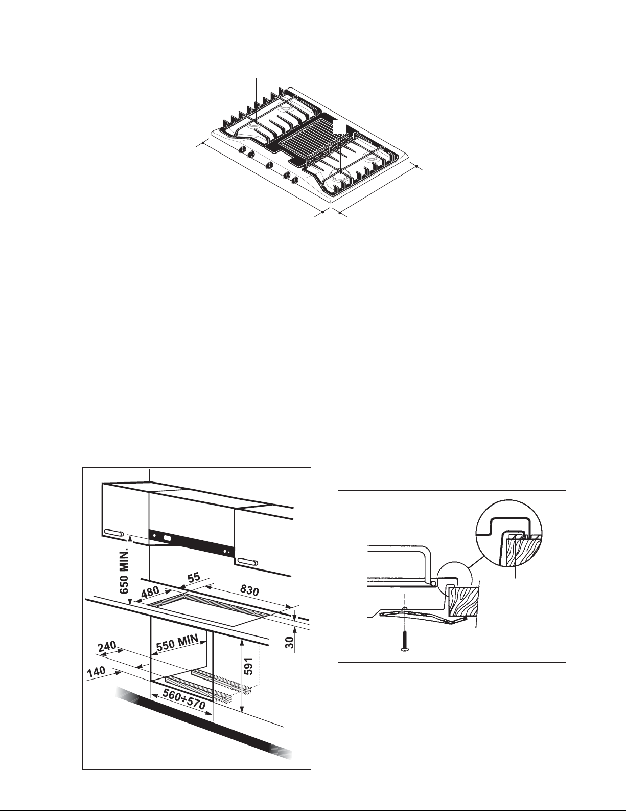
The cooktops must be fitted on a cabinet having an opening with the dimensions given in Fig. 19.
The opening for fitting must be at least 55 mm from the
back wall.
Possible right or left side walls higher than the cooktop
must be at least 150 mm from the opening in the top.
Models PX 95 BOV and PX 95 COV: adjacent cabinets
must not be higher than the worktop.
The top must be fixed to the cabinet as follows:
A = Auxiliary burner
SR = Semirapid burner
R = Rapid burner
B = Broiler
Dimensions in mm
This top is designed for fitting on modular kitchen
cabinets having a depth of between 550 and 600 mm and
appropriate characteristics.
The dimensions of the tops are given in the figures.
Fitting on modular cabinets
510
860
A
SR
B
SR
R
● apply the special seal (supplied), on the edge of the
opening, making sure the ends match without overlapping;
● arrange the top in the cabinet opening, making sure it
is centred;
● fix the top to the cabinet with the special brackets (see
Fig. 20). The pressure of the screws is sufficient to
mark the seal, so that the excess can be easily
removed.
The edge of the top forms a double labyrinth seal preventing any penetration of liquids.
Dimensions in mm
Fig. 19
Fig. 20
FO 0199
a
a) Seal
Page 11
11
Fitting possibilities
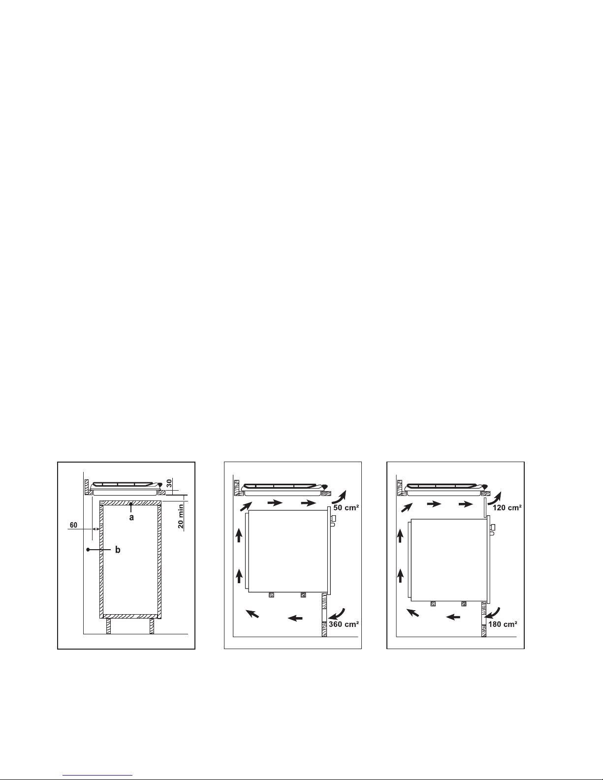
On base cabinet with door
Adequate arrangements must be provided for in the construction of the cabinet, to prevent possible contact with
the overheated housing of the top during operation. A
possible solution for avoiding this problem is illustrated
in fig. 21.
The panel under the top must be easily removed to allow
securing and release of the top in case of technical assistance intervention.
On base cabinet with oven
The compartment must have the dimensions given in
fig.19 and must be equipped with supports for allowing
efficient ventilation.
Two possible solutions for preventing overheating are
described in fig. 22 and 23.
The electrical connection of the top and that of the oven
must be carried out separately , for electrical reasons and
to facilitate frontal oven removal.
Wall units or extractor hoods must be at least 650 mm
from the cooktop (Fig. 19).
a) removable cabinet panel
b) possible space useful for
connections
Fig. 21
Fig. 22 Fig. 23
Page 12

02/06
Grafiche MDM - Forlì
 Loading...