

Electrolux EFC925SAR, EFC926BAR User Manual
2 3
WE’RE THINKING OF YOU
Thank you for purchasing an Electrolux appliance.
You’ve chosen a product that brings with it decades
of professional experience and innovation. Ingenious
and stylish, it has been designed with you in mind.
So whenever you use it, you can be safe in the
knowledge that you’ll get great results every time.
Welcome to Electrolux.
BEFORE USING YOUR APPLIANCE
Before you use the rangehood, we recommend that you
read through the whole user manual which provides
the description of the rangehood and its functions. To
avoid the risks that are always present when you use an
electrical appliance, it is important that the rangehood is
installed correctly and that you read the safety instructions
carefully to avoid misuse and hazards.
For future reference, please store this booklet in a
safe place.
CONDITIONS OF USE
This appliance is intended to be used in household and
similar applications such as:
• Staff kitchen areas in shops, offices and
other working environments
• Farm houses
• By clients in hotels, motels and other residential
type environments
• Bed and breakfast type environments
BEFORE YOU CALL
Please ensure you read the instruction manual fully before
you call for service, or a full service fee could be applicable.
RECORD MODEL AND SERIAL
NUMBER HERE:
Model:
Serial No:
CONTENTS
3 Safety information
4 Product description
5 Dimensions
6 Rangehood installation
10 Using the rangehood
11 Maintenance and cleaning
12 Troubleshooting
13 Customer Care Center
LEGEND
WARNING!
This symbol indicates information concerning your
personal safety.
CAUTION!
This symbol indicates information on how to avoid
damaging the rangehood.
IMPORTANT!
This symbol indicates tips and information about use of
the rangehood.
ENVIRONMENT!
This symbol indicates tips and information about
economical and ecological use of the rangehood.
SAFETY INFORMATION
This manual explains the proper use of your new Electrolux
canopy rangehood. Please read this manual carefully
before using the product. This manual should be kept in a
safe place for handy reference.
This canopy rangehood is a domestic appliance which has
been manufactured and tested to comply with International
Standard IEC 60335.2.31.
Read the following carefully to avoid damage or injury.
This symbol indicates never to do this
This symbol indicates always do this
WARNING!
Follow these instructions carefully to avoid an electric
shock or
Young children should be supervised to ensure they
do not play with the canopy rangehood.
This appliance is not intended for use by persons
(including children) with reduced physical, sensory
or mental capabilities, or lack of experience and
knowledge, unless they have been given supervision
or instruction concerning the use of the appliance by
a person responsible for their safety.
Ensure the canopy rangehood is switched off before
carrying out maintenance, to avoid any possibility of
electric shock.
Never carry out flambé cooking under the canopy
rangehood.
This canopy rangehood is not recommended for
barbecues.
This canopy rangehood cannot be installed for
external use
Grease filters must be removed every four weeks
(maximum) for cleaning to reduce the risk of fire.
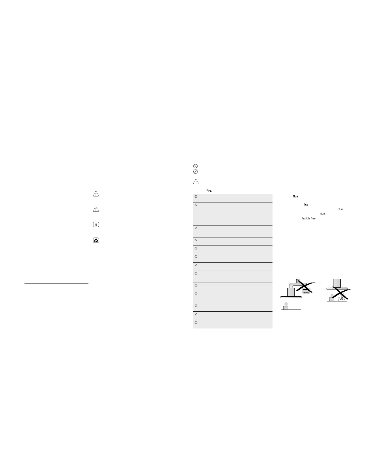
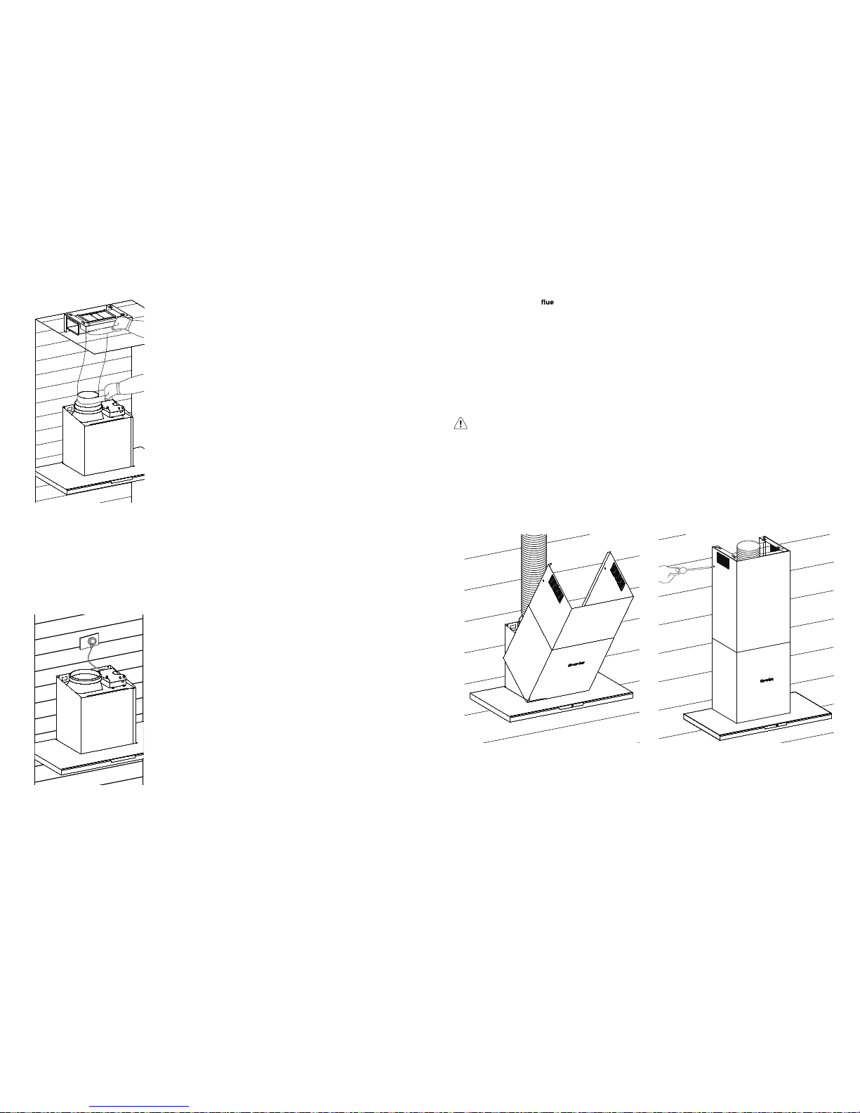
The exhaust from the canopy rangehood must not
be discharged into any heating flue, which may carry
combustion products from other sources. (Fig. 1)
Exhaust air must not be discharged into a wall
cavity, unless the cavity is designed for the purpose.
There must be adequate ventilation of the room
when the canopy rangehood is used at the same
time as appliances burning gas or other fuels.
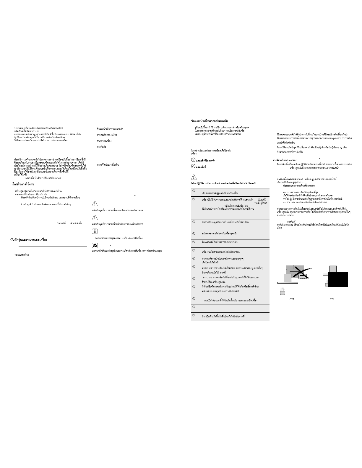
Always cover lit gas burners with pots or pans when
canopy rangehood is in use.
Always switch off gas burners before you remove
pots or pans.
Do not leave lit gas burners exposed due to the risk
of fire. (Fig. 2)
Electrical connection
Check that the mains voltage matches with the voltage on
the data plate inside the canopy rangehood. Check that
the installation complies with standards of local building,
gas and electrical authorities. Before connecting to the
mains supply ensure that the mains voltage corresponds
to the voltage on the rating plate inside the cooker hood.
If the supply cord is damaged, it must be replaced by
the manufacturer or its service agent or similarly qualified
person in order to avoid a hazard.
Safety warnings – For the installer
When installing th
e cooker hood, make sure you adhere
to the minimum and maximum distances from the cooker
hood base to the hob surface (as per table on page 6).
Exhaust
installation: The following rules must be
strictly followed to obtain optimal air extraction.
• Keep exhaust
short and straight
• Do not reduce the size or restrict exhaust
• Keep bends in the exhaust
to a minimum.
• When using always install duct with helix
pulled taut to minimise pressure loss.
• Failure to observe these basic instructions will
drastically reduce the performance and increase the
noise levels of the cooker hood.
Exhaust air must not be discharged into a wall cavity,
unless the cavity is designed for that purpose. The exhaust
from the cooker hood must not be discharged into any
heating flue, which may carry combustion products from
other sources
NOTE: Some installations may require the telescopic
exhaust cover to be cut to length. Cut with sharp tin
snips or a fine-tooth hack saw blade, taking care not to
distort or dent the exhaust cover.
Fig. 1 Fig. 2
4 5
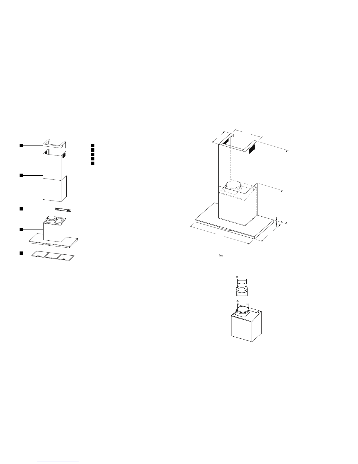
PRODUCT DESCRIPTION DIMENSIONS
1
Ceiling mount bracket
2
Telescopic flue cover set
3
4
Wall bracket
5
Main body and fan housing assembly
Grease filters
additional items required for installation
• ixiF ngs required to attach rangehood body and anti tilt
points.
• ixiF ngs required to attach ceiling mounting bracket and
hood bracket to the wall.
• ac ro epat tcuD ble ties.
Technical Specification
Power supply: 220-240 Volts 50Hz. Connects to
7.5A power point.
Lights: LED 1 x 8.5 watt, 12 Volt LED
1
2
3
4
5
Fig. 3
NOTE:
1) The fan housing
transition duct is 180mm in diameter.
2)
Flue transition duct 180mm to 150mm is for external venting
and Recirculation mode.
400mm
480mm
500mm
895mm
180mm
150mm
38mm
320mm
1120mm
(Maximum)
Fig. 4
Fig. 5
6 7
4. Remove protective plastic film, if present, from the hood
body and hang on the wall bracket.
Install the two anti-tilt fasteners.
RANGEHOOD INSTALLATION
WARNING!
Refer to “Safety information” chapter.
BEFORE INSTALLATION
Before the installation of the appliance, record the information
below from the rating plate. The rating plate is on the bottom
of the appliance casing.
Model
PNC
Serial number
1.
2.
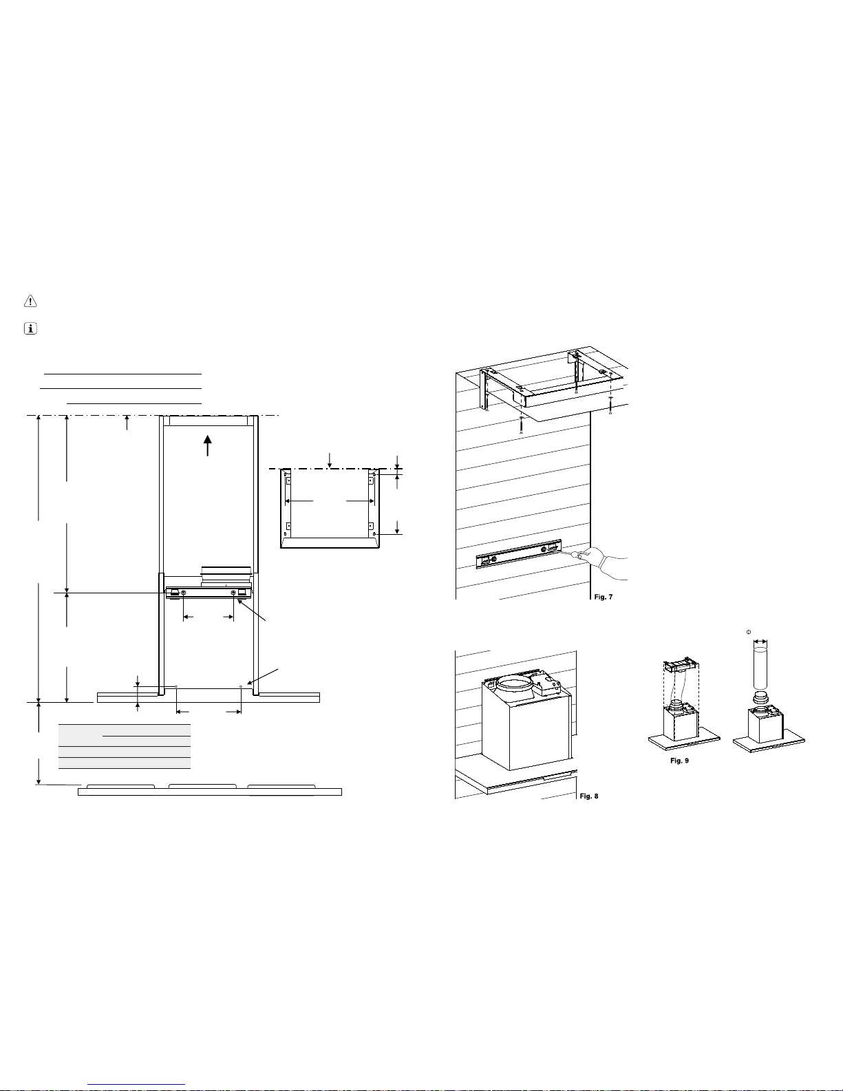
Using a spirit level mark a vertical centre line on the wall
where the hood is to be positioned, and a horizontal line
at the hood base position (refer diagram below).
NOTE: The height of the underside of the hood body must
be a minimum of 600mm* to a maximum height of 800mm.
* If the instructions of the hob specify a greater distance than the minimum above,
then that shall be the minimum height for installation.
Mark the location for flue cover wall mounting brackets
and cooker hood mounting points and anti-tilt fixing
points above the hood base using the hood base as
the reference point (Fig. 6).
RANGEHOOD INSTALLATION (CONT)
3. Install flue cover wall mounting brackets with suitable
fixings. Install suitable screws for cooker hood mounting
points (to support a total weight of 30kg) to the wall as
marked (Fig. 6).
Depending on the preferred installation/ducting mode,
follow step 5a or 5b below.
5a. Recirculating mode (Fig. 9).
Using the centre line, secure the recirculating T-piece to the
wall with suitable screws/fixings. Install flexible pipe between
T-piece and the exhaust transition duct. Use cable ties or
suitable duct tape to secure flexible pipe to T-piece and
transition duct (Fig. 11).
NOTE: When installed in recirculating mode, it is
recommended to use a carbon lter to prevent odours
being emitted back into the room.
5b. Ducted mode (Fig 10.)
The canopy rangehood has been supplied with a duct
transition and 150mm diameter flexible flue. Fit the flexible
flue to the duct transition (Fig. 10). Use cable ties or
suitable duct tape to secure flexible pipe to the duct
transition.
NOTE: For ducted mode, we recommend extending
ue pipe through the roof to external “china hat” to vent
exhaust externally. We do not recommend venting into
ceiling cavity.
NOTE: To ensure optimum performance of the
rangehood, the use of rigid ducting is recommended.
The use of bends should be avoided. All ducting must
be re retardant
Top of hob
Max. 1158
mm
ceiling
View A
View A
200 mm
260 mm
441 mm
DIM. A
240 mm
21 mm
58 mm
718 mm
installaon wall
360 mm
Fig. 6
Cooktop
type
DIM. A
minimum* maximum
Gas 650mm 800mm
Electric 600mm 800mm
150mm
Fig 10
Anti-tilt fixing points
Range hood mounting points
8 9
RANGEHOOD INSTALLATION (CONT) RANGEHOOD INSTALLATION (CONT)
Fig. 11
6. Electrical connection
Check that the installation complies with the standards
of local building, gas and electrical authorities. Before
connecting to the mains supply ensure that the mains
voltage corresponds to the voltage on the rating plate
inside the rangehood.
Fig. 12
installation of telescopic
covers
Separate the inner and outer flue covers. Carefully
reassemble the upper and lower flue covers sections by
sliding the inner into the outer flue cover. Carefully lower
the assembled upper and lower flue covers onto the top
of the rangehood body. and insert the flue cover into the
rangehood body approximately 5mm. Fix upper flue cover
to the wall mounting bracket with screws supplied. Ensure
that the upper section is extended.
NOTE: Carefully remove the plastic protec
tive coating,
if present, from the flue covers. Pay particular attention
when removing protective plastic coating from decals.
IMPORTANT!
Care must be taken to ensure the screws are not cross
threaded when attaching the upper flue cover. If installed
in recirculating mode, insert the carbon filter
To complete the rangehood installation, insert the three
Your Electrolux rangehood is now ready to use.
Fig. 13 Fig. 14
filters to the underside of the hood body. Place back edge
of filter into position and push up front edge so that the
filter clips into place.
10 11
MAINTENANCE AND CLEANING
CAUTION!
• Before maintenance or cleaning is carried out,
the canopy rangehood should be disconnected
from the main power supply. Ensure that the
rangehood is switched off at the wall socket and
the plug removed.
• External surfaces are susceptible to scratches
and abrasions, so please follow the cleaning
instructions to ensure the best possible result is
achieved without damage.
• These instructions must be followed to avoid a
risk
Stainless Steel Surface
Clean stainless steel surfaces using non-abrasive cleaning
products that are specifically for use on stainless steel. To
ensure best results also use an even pressure and follow
the grain of the stainless steel. Use of a soft cloth reduces
the risk of scratching. If the cloth is wet ensure that a dry
soft cloth is used to wipe down the surface again reducing
the risk of any surface rust appearing.
Control panel surface
The control panel can be cleaned using warm soapy
water. Ensure the cloth
is well wrung before cleaning. Use
a dry soft cloth to remove any excess moisture left after
cleaning.
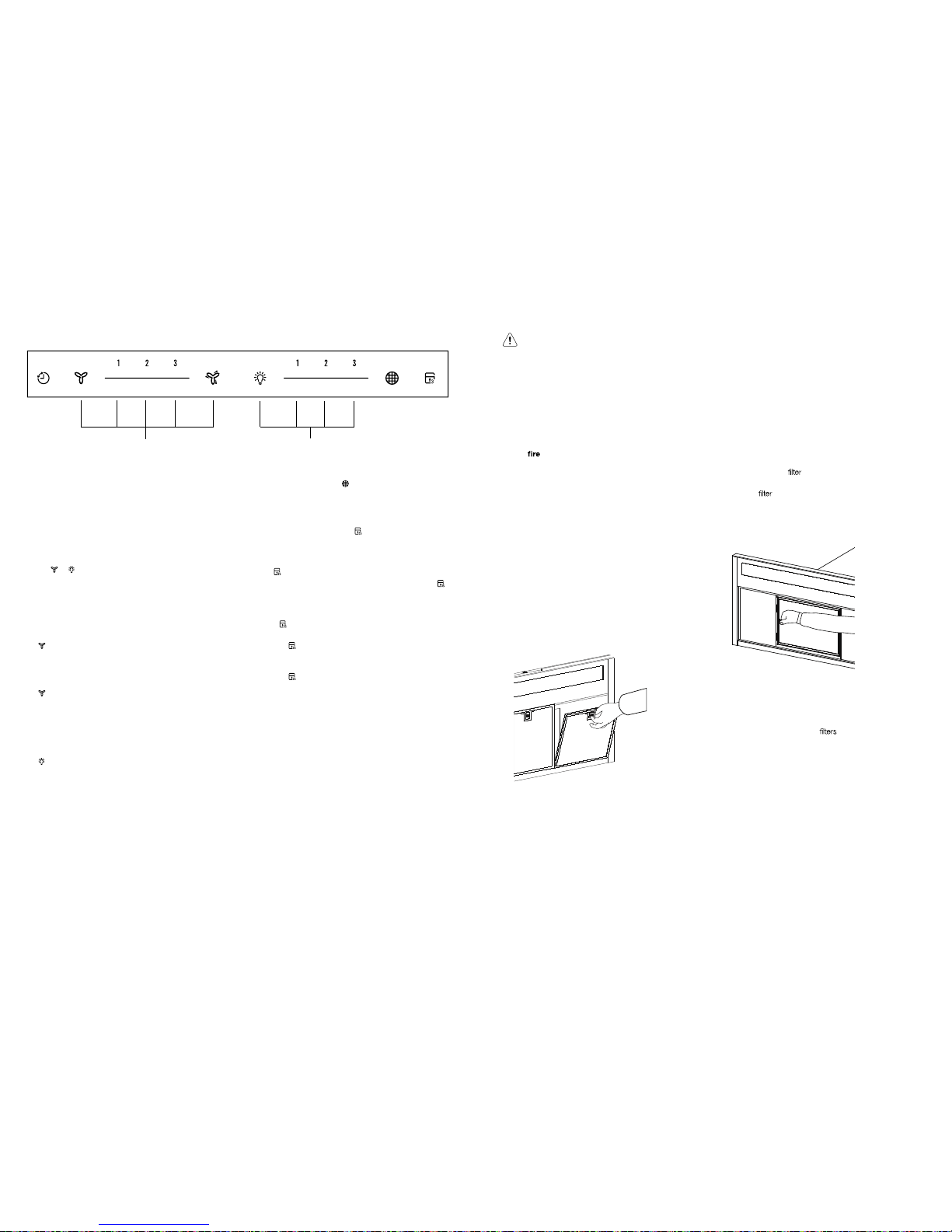
Removing the metal grease lters
Push the grease filter towards the left side of the unit and
then pull it down.
Hand washing
The mesh filters can be cleaned by hand in warm soapy
water. Soak in warm water and some washing up liquid.
For stubborn grease stains use a soft nylon brush to help
remove these stains. After cleaning ensure that the filters
are completely dry before refitting.
USING THE RANGEHOOD
Standby mode
When connecting the hood to the power supply for the
first time or after power is returned after power outage, all
symbols on the control panel will light up from left to right
and a “beep” will sound once. Fol
lowing this, the control
panel goes to standby mode and the hood will be ready
for use.
Turning on hood
When the hood is in standby mode, user can either press
the
or button to turn on the fan or light individually.
The default factory level is 2, following that, the hood
remembers the last used setting and will start at that level
when the user presses the fan or light button. Pressing
directly on the slider strip will also allow the user to jump
straight into the level pressed.
Fan – select speed to suit cooking conditions.
– motor on/off
1 – light frying/boiling
2 – frying/wok cooking/heavy boiling
3 – grilling, intensive frying and wok cooking
– stir frying
NOTE: Touch the symbol to turn the fan boost ON, the
fan boost starts running at the highest fan speed for 1
minute before reducing to speed 3 automatically.
Light – select light level
– Light on/off
1 – low-light level
2 – mid-light level
3 – high-light level
Using the Timer
At the end of cooking, if the timer is switched on, the
rangehood will continue to run for an additional 5 minutes,
depending on the selected fan speed. This should ensure
the removal of any odours that remain after cooking.
Filter
This is the indicator/switch
to show when the filter needs
to be cleaned. Once the filters are cleaned the “Filter” alert
can be deactivated with a single touch.
Control Lock
Press and hold 3 seconds the
. button will lock the
control panel at any time. The same action will unlock the
control panel.
When control is locked, pressing any other button will
make
. button blink and a beep will sound.
• When the hood is working (light on and fan on) and
is touched then hood will stop fan but keep lighting on
while lock menu.
• When the hood is working (lights off and fan on) and
the
is touched then hood will stop fan and keep
lighting off while lock menu.
• When
is activated when hood is working it will just
change the status of fan motor and not change the
status of lighting.
• When
is touched while hood stops then it will just
lock the menu
Dishwasher
Place grease filters in the dishwasher. Select the most
powerful washing program and highest temperature, at
least 65°C. Repeat the process. Refit the grease filters
when they are dry. When washing the metal grease filter
in the dishwasher a slight discolouration of the filter can
occur, this does not have any impact on it’s performance.
Changing the lamps
Lamps are long life LED lamps and should not require
service. If there is an
issue with lamps please contact
Service. Service contact details shown on page 13.
Charcoal lter
• The charcoal
should only be used if you want to
use the hood in the recirculation function.
• This
cannot be cleaned or re-used and as a
general rule, the activated charcoal filter should be
changed once every four months.
Open or fit the charcoal filter as shown in the image below.
• Always specify the hood model code number and
serial number when ordering replacement filters. This
information is shown on the registration plate located
on the inside of this unit.
• Replacement charcoal
can be ordered from your
local Spare parts centre, contact details are shown on
page 13.
S
Fan Light
12 13
TROUBLESHOOTING
Problem Remedy
The cooker hood will not start Check that the hood is connected to an electrical supply
Check that a fan speed has been selected
The cooker hood is not working Check that the fan speed is set high enough for the task
The grease filters are clean
The kitchen is adequately vented to allow the entry of fresh air
If set up for recirculation, check that the charcoal filter is still effective
If set up for extraction, check that the ducting and outlets are not blocked
Do not operate cooktop without pots/pans
Do not flambe under cooktop
The cooker hood has switched
off during operation
The safety cut-out device has been tripped – turn off the hob and wait for the device
to reset. If the hood has been installed below the heights
indicated in the installation
instructions the motor will cut out frequently which will damage the hood
If you have completed all of the above checks and are still
experiencing difficulty, please contact your local Electrolux
Service Centre.
NOTE: This product is fitted with a safety cu
tout device.
• If the cooker hood is installed too close to the cooktop,
flambe cooking, operating the cooktop without
cooking utensils and blocked filters may activate
the safety cutout device. If the hood stops during
operation, correct the faults and allow time for the
safety cutout device to reset, the cooker hood will then
function correctly.
• Do not operate cooktop without pots/pans
• Do not
under cooktop
Domestic Toll Free : 1-800-10-845-care 2273
Customer Care Hotline : (+63 2) 845 care 2273
Electrolux Philippines, Inc.
10th Floor. W5th Avenue Building
5th Avenue Corner 32nd Street
Bonifacio Global City,
Taguig Philippines 1634
Trunkline: +63 2 737- 4756
Website : www.electrolux.com.ph
Email : wecare@electrolux.com
2 3
WE’RE
THINKING OF
YOU
กอืลเดไนาทบักาทเ
มอรพ ษรรวศทาวกามพีชาออืมบัดะรมรรกตัวนะลแ
ซกัลรทโ กึสูระจนาท
ซกัลรทโคลเีองอขกลโูสบัรนอตอข
กอนใชงานเครืองดูดควัน
ณรกปุอชใรากกาจ
า
โปรด ืมูคบ็กเ
:
:
•
•
บานสวน
•
•
หองนอน และบริเวณเตรียมอาหารเชา
กอนติดตอ ศูนยบ ริก าร
รากิรบบัรอขอตดิตนอกนางชใรากอืมูคนาอดรปโ เรียก
แกปญหาตามรายการ อืมูคนใ บริษัท ธทิสนวงสอข รากิรบาคดิครากนใ
:
นุร :
(Serial No
):
ญับราส
3
4
5
6
10 การใชงาน
11
ดาอะสมาวคาํทะลแาษกัรลแูดราก
12
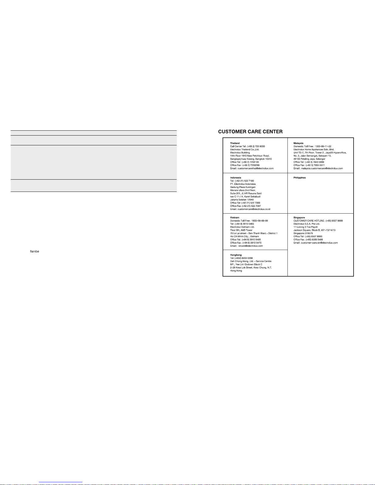
ศูนยบริการลูกคา
13
สัญลักษณตางๆทีใชในคูมือฉบับนี:
นอืตเาํค!
งัวะรรวคอข!
ขอควรทราบ
!
แส
ขอมูลดานสิงแวดลอม
!
ายทิวศวเินกัลห
นาทงอขมหในุรนัว
อตยาหยีสเมาวคะลแชใ ูผอตยารตนัอ
าํทรวค
นอืตเาํค!
อไฟไหม
และ
ความบกพรองทางรางกาย ูรบัรทาสะรปงาท จใติจงาทอืรห
ูรมาวคะลแณรากบสะรป อืรหลแูดมุคบวคูผีมมไ
4 )ดุสงูส( หาดปัส
( 1)
ท
ไม
/
อมหาอเนอกสกแวัหดิป /กระทะออกจากเตาแกส
2)
การตอระบบไฟ
ยัภดอล – สําหรับผูติดตัง
นาฐกาจดุสงูส
6)
:
นัวคดูด
•
•
ห ศากาอยาบะรอทดานขดลมา
•
•
•
ทธิภาพใน
หมายเหตุ:
หใกออกิปคโสลเทเงอลปบอรคาฝดัตงอตน็ปเาํจจาอดุจงาบนใง
หรือเสียรูป
1
2
ผลิตภัณฑ์นี้เป็นเครื่องใช้ไฟฟ้าสำหรับใช้ในบ้าน ซึ่งผลิตและทดสอบตรงตามมาตรา
ฐานนานาชาติ IEC 60335.2.31
 Loading...