

Page 1
Gebrauchsanweisung , Notice d'utilisation et d'installation, Installatie- en gebruiksaanwijzing
EFC 1460
EFC 1420
User manual, Istruzioni per l'uso,
Instrucciones de montaje y manejo, Manual de Instruções
EFC 1420
D
F
NL
UK
EFC 1460
I E P
Page 2
Sommaire
Consignes de sécurité ...................................................................................................................................... 16
pour l’installateur.................................................................................................................................................... 16
pour l’utilisateur ..................................................................................................................................................... 16
Généralités ......................................................................................................................................................... 17
Version évacuation extérieure................................................................................................................................17
Version recyclage .................................................................................................................................................. 17
Utilisation de la hotte - EFC 1460 .................................................................................................................. 17
Utilisation de la hotte - EFC 1420 .................................................................................................................. 18
Entretien ............................................................................................................................................................. 19
Nettoyage .............................................................................................................................................................. 19
Filtre à graisse métallique ...................................................................................................................................... 19
Ouverture du filtre à graisse métallique .................................................................................................................19
Filtre à charbon ......................................................................................................................................................20
Remplacement de l´ampoule d’éclairage ...............................................................................................................20
Accessoires (en option) .................................................................................................................................... 21
F
Service Après-vente ......................................................................................................................................... 21
Caractéristiques techniques ............................................................................................................................ 21
Installation .......................................................................................................................................................... 22
Déballage ...............................................................................................................................................................22
Montage .................................................................................................................................................................22
Branchement électrique .........................................................................................................................................22
Accessoires/Matériel de montage ......................................................................................................................... 23
Informations préliminaires pour l’installation de la hotte ........................................................................................ 23
Fixation ................................................................................................................................................................. 24
Avant d’utiliser votre hotte aspirante, nous vous recommandons de lire attentivement la totalité de ce mode
d`empoli décrivant votre appareil et toutes ses fonctions particulières.
Pour prévenir tout risque inhérent aux appareils électriques, il est indispensable que la hotte aspirante soit
installée correctement. Lisez attentivement les mesures de sécurité pour éviter toute utilisation abusive ou
danger. Conservez précieusement le mode d’emploi afin de vous permettre de le consulter à tout moment.
15
Page 3

Consignes de sécurité
Cet appareil doit être installé par une personne qualifiée et
selon les normes en vigueur.
pour l’installateur
• Le tuyau d’évacuation doit présenter un diamètre de
150 mm en version évacuation.
Seulement pour le modèle EFC 1460 X / 942 120
706:
Dans le cas où il existe déjà un tuyau d’évacuation de
l’air d’un diamètre de 125 mm dans le mur ou sur le
toit, on pourra utiliser le manchon de réduction 150/125
mm. Le bruit de fonctionnement sera un peu plus élevé.
• Lors de l’installation de la hotte, respectez les
distances minimales suivantes entre le plan de
cuisson et le bord inférieur de la hotte:
Cuisinière électrique 500 mm
Cuisinière à gaz 650 mm
Cuisinière au charbon
ou au mazout min. 700 mm
• L'appareil doit être débranché pendant l'installation ou
dans l'éventualité d'une intervention.
• L'installation de votre appareil doit être réalisée par un
technicien qualifié.
• Vérifiez que la tension du réseau correspond à la
tension mentionnée sur la plaque signalétique sur la
hotte.
• Si l'installation électrique de votre habitation nécessite
une modification pour le branchement de votre appareil,
faites appel à un électricien qualifié.
• Le conduit d'évacuation, quel qu'il soit, ne doit pas
déboucher dans les combles.
• Dans le cas où l'appareil est relié directement à
l'installation électrique, interposez un interrupteur
bipolaire ayant une distance d'ouverture des contacts
d'au moins 3 mm.
• La dépression de l’air dans la pièce où se trouvent des
systèmes de chauffage ne doit pas être supérieure à
4Pa (4x10
hotte aspirante en version évacuation et des systèmes
de chauffage.
• Si la hotte est utilisée en version évacuation, ne
raccordez pas l'appareil à un conduit d'évacuation de
fumées de combustion (chaudière, cheminée, etc.) ou à
une VMC (ventilation mécanique contrôlée).
L’évacuation de l’air aspiré doit se faire selon les
prescriptions locales en vigueur.
• Lors du fonctionnement en Version évacuation, il faudra
veiller à réaliser une ouverture d’entrée d’air suffisante,
environ de la taille de l’ouverture d’évacuation.
• Selon les prescriptions de construction locales, des
restrictions sont imposées à l’utilisation simultanée dans
une même pièce de hottes aspirantes et de systèmes de
chauffage reliés à une cheminée tels que des poêles à
charbon, à mazout ou à gaz.
• Le fonctionnement simultané et sans danger d’appareils
reliés à une cheminée et de hottes aspirantes n’est
assuré que si le local et/ou l’appartement (pièces
communicantes) possède une entrée d’air adaptée
d’env. 500 à 600 cm
lorsque la hotte est en service.
• Comme dans les pièces sans systèmes de chauffage la
règle suivante est de mise : «Ouverture d’entrée d’air
-5
bar) lors du fonctionnement simultané de la
2
, empêchant ainsi une dépression
aussi importante que l’ouverture d’évacuation», le
rendement de l’installation d’évacuation peut être
réduit si l’entrée d’air est supérieure à 500 à 600 cm
• Le fonctionnement de la hotte en recyclage ne
présente aucun danger dans des conditions connues
et n’est donc pas soumis aux prescriptions mentionnées ci-dessus.
• Le fonctionnement de la hotte en version évacuation
n’est optimal que si les conditions suivantes sont
respectées :
—parcours d’évacuation court et direct
—nombre de coudes minimal sur les tuyaux
—pose des tuyaux avec des courbes plutôt que
des angles nets
—diamètres des tuyaux les plus grands possibles
(de préférence le même diamètre que celui de
l’ouverture d’évacuation).
• Le non respect de ces règles de base entraînera des
pertes de puissance significatives et une
augmentation du niveau sonore.
pour l’utilisateur
• Il est recommandé de ne jamais laisser les foyers de
cuisson sans récipient dessus. En cas de cuisinières à
gaz, à mazout ou à charbon il faut absolument éviter
toute flamme libre.
• Par ailleurs, en cas de friture il faut faire attention à
la friteuse placée sur le plan de cuisson. En effet
l’huile pourrait prendre feu à cause d’une surchauffe.
Le risque augmente si l’on utilise de l’huile usagée.
• Il est rappelé que toute surchauffe peut provoquer un
incendie.
• L’utilisation d’huile usagée peut entraîner plus facile-
ment une auto-inflammation.
• Flamber est strictement interdit sous la hotte.
• Pour toute intervention sur la hotte, y compris
pour le remplacement d’une ampoule électrique,
mettez l’appareil hors tension (retirez les fusibles
ou ouvrez les disjoncteurs).
• Respectez les intervalles de remplacement du filtre et
de nettoyage.
Le non respect des consignes d’entretien et de
nettoyage peut entraîner un risque d’incendie suite à
l’accumulation de graisse dans le filtre.
• Cet appareil a été conçu pour être utilisé par des
adultes. Veillez à ce que les enfants n’y touchent pas
et ne l’utilisent pas comme un jouet.
• Votre appareil est destiné à l’usage domestique
normal. Ne l’utilisez pas à des fins commerciales ou
industrielles ou pour d’autres buts que celui pour
lequel il a été conçu.
• Ne modifiez pas ou n’essayez pas de modifier les
caractéristiques de cet appareil. Cela représenterait
un danger pour vous.
• Débranchez toujours la hotte avant de procéder à son
nettoyage et son entretien.
• Aérez convenablement la pièce en cas de
fonctionnement simultané de la hotte et d’autres
appareils alimentés par une source d’énergie
différente de l’énergie électrique. Ceci afin que la
hotte n’aspire pas le gaz de combustion.
2
.
16
Page 4
Généralités
D
• La hotte est livrée en version évacuation mais peut, grâce à
l’emploi d’un filtre à charbon actif (en option), être utilisée en
version recyclage.
• Pour cela, il faudra vous procurer le filtre à charbon actif
d’origine ELECTROLUX (voir Accessoires).
Version évacuation extérieure
• L’air est rejeté à l’air libre par un conduit
raccordé sur le tuyau d’évacuation. Fig. 1.
• Pour obtenir des performances optimales lors de
l’aspiration, le tuyau d’évacuation doit avoir un
diamètre équivalent à celui de l’ouverture
d’évacuation.
Version recyclage
• L’air est filtré par un filtre à charbon (en option)
et renvoyé dans la pièce.
• En version recyclage utilisez le filtre à charbon
actif KF20 d’origine ELECTROLUX (voir
Accessoires) que vous pourrez vous procurer
en option auprès de votre magasin vendeur.
• Fixez le déflecteur d’air au moyen des 4 vis Ø
3,5x13 mm. Fig. 2.
Attention!
Le modèle EFC 1420 avec chemin sans ouvertures
laterales est fourni sans déflecteur d’air et sans vis
de fixation.
tuyau
d’évacuation
Fig. 1
F
Fig. 2
Utilisation de la hotte - EFC 1460
• La hotte est équipée de vitesse réglable. Il est conseillé de mettre en marche la hotte quelques minutes avant
le début de la cuisson et de la laisser fonctionner env. une quinzaine de minutes après la cuisson afin
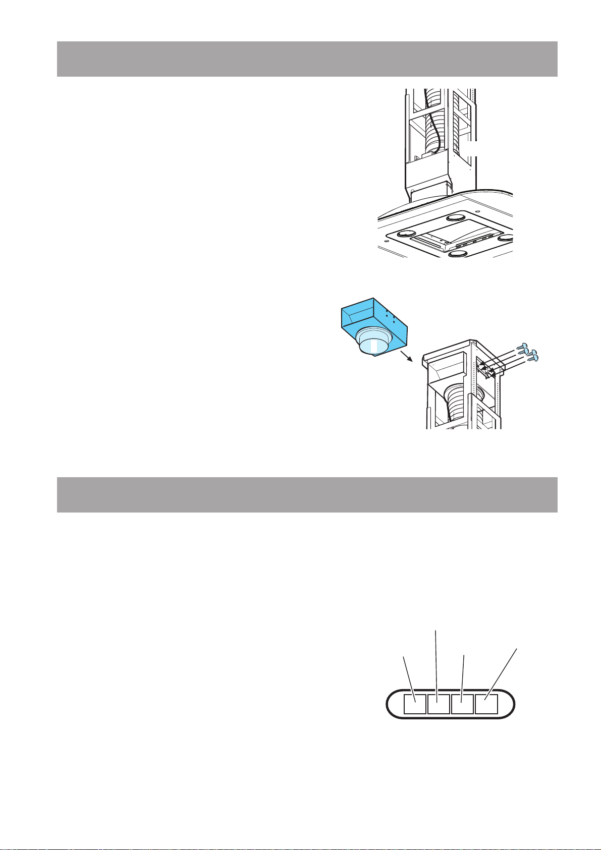
d’éliminer toutes les odeurs. Le bandeau de commandes de la hotte se trouve sur l’avant de l’appareil.
• Commutateur d’éclairage : Ce commutateur
sert à allumer ou à éteindre la lampe dont est
équipée la hotte aspirante.
• Commutateur ON/OFF moteur marche
vitesse 1 : Ce commutateur sert à
l'enclenchement de la 1ère vitesse du
ventilateur.
• Vitesse 2 : Ce commutateur sert à
l'enclenchement de la 2ème vitesse du
ventilateur.
• Vitesse 3 : Ce commutateur sert à
l'enclenchement de la 3ème vitesse du
ventilateur.
Pour une ventilation optimale
Pour assurer le bon fonctionnement de la hotte,
fermez la fenêtre de la cuisine. En revanche, vous
pouvez ouvrir une fenêtre d’une pièce contiguë .
Commutateur
d’éclairage
Commutateur
ON/OFF moteur
marche vitesse 1
Vitesse 2
Fig. 3
Vitesse 3
17
Page 5
Utilisation de la hotte - EFC 1420
• La hotte est équipée de vitesse réglable. Il est conseillé de mettre en marche la hotte quelques minutes
avant le début de la cuisson et de la laisser fonctionner env. une quinzaine de minutes après la cuisson
afin d’éliminer toutes les odeurs. Le bandeau de commandes de la hotte se trouve sur l’avant de
l’appareil.
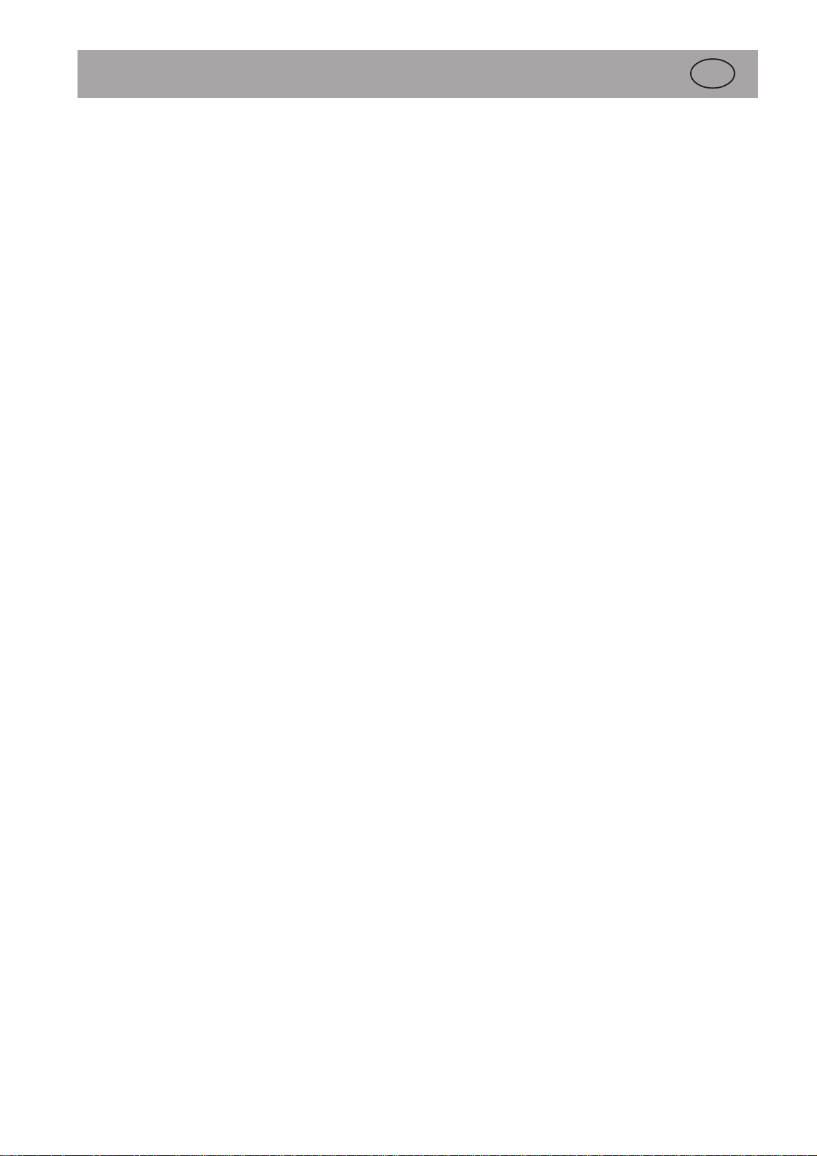
ABCDEFGH I
Fig. 4
A - Interrupteur d’arrêt
B - Interrupteur de marche et sélection des
vitesses 1-2-3-1-2-........
C - Vitesse 1 (voyant)
D - Vitesse 2 (voyant) et saturation filtre à
graisse (voyant clignotant)
E - Vitesse 3 (voyant) et saturation filtre à
charbon (voyant clignotant)
F - Vitesse intensive (Voyant)
G - Interrupteur de vitesse intensive :
A l’issue de cette durée, la hotte
fonctionne à la vitesse initialement
sélectionnée ou s’arrête si aucune vitesse
n’est réglée. Pour arrêter la hotte en
vitesse intensive avant l’écoulement des 5
minutes, appuyez sur la touche A ou B
H - Interrupteur d’arrêt d’éclairage
I - Interrupteur de fonctionnement
d’éclairage.
Coupez l’alimentation de la hotte pendant au moins
5 secondes puis remettez la hotte en
fonctionnement.
Dispositif de contrôle de
saturation du filtre à graisse et
du filtre à charbon actif
Cette hotte est équipée d’un dispositif qui signale
lorsque le filtre à graisse et éventuellement le filtre
à charbon actif doivent être nettoyés.
La hotte est fournie sans filtre à charbon actif;
c’est pourquoi le dispositif signalant la saturation du
filtre à charbon actif est déconnecté.
Si l’on désire installer un filtre à charbon actif, il
faut alors activer le dispositif en appuyant
simultanément sur les touches B et G pendant 3
secondes : au début il n’y a que LE VOYANT DE
SATURATION FILTRE À GRAISSE D qui
clignote, puis au bout de 3 secondes
LE VOYANT DE SATURATION FILTRE À
CHARBON E commence également à clignoter
indiquant ainsi que le dispositif de contrôle de
saturation du filtre à charbon est à présent actif.
Pour l’exclure, appuyez à nouveau sur les deux
touches: au bout de 3 secondes; LE VOYANT DE
SATURATION FILTRE À CHARBON E arrêtera
de clignoter.
Voyant de saturation du filtre à
graisse (D)
Ce voyant clignote lorsque le filtre à graisse doit
être nettoyé. Ceci se produit après 40 heures
environ d’utilisation.
Lisez attentivement les conseils pour
l’entretien du filtre à graisse.
Voyant de saturation du filtre à
charbon (E)
Ce voyant clignote lorsque le filtre à charbon doit
être remplacé. Ceci se produit après 160 heures
environ d’utilisation.
Lisez attentivement les conseils sur le
remplacement du filtre à charbon actif.
Rétablissement de la
signalisation de saturation du
filtre à graisse et du filtre à
charbon
Après avoir nettoyé le filtre à graisse ou remplacé
le filtre à charbon, appuyez sur la touche A pendant
3 secondes environ jusqu’à ce que le voyant de
saturation du filtre à graisse D ou le voyant de
saturation du filtre à charbon E arrête de clignoter.
Pour une ventilation optimale
Pour assurer le bon fonctionnement de la hotte,
fermez la fenêtre de la cuisine. En revanche, vous
pouvez ouvrir une fenêtre d’une pièce contiguë .
18
Page 6

Entretien
• Débranchez la hotte avant tout entretien.
Nettoyage
• Attention: Débranchez l’appareil avant le
nettoyage.
N’introduisez pas d’objets pointus dans la grille
de protection du moteur.
• Nettoyez les parties extérieures avec un
détergent doux.
N’utilisez jamais de produits abrasifs ou
caustiques, de détergents corrosifs, de brosses
ou de sablons à récurer.
• Nettoyez le bandeau des commandes et la grille
du filtre à graisse avec un chiffon légèrement
imbibé d’un détergent doux.
• Il est très important de respecter les intervalles
de remplacement du filtre et de nettoyage. Le
non respect peut entraîner un risque d’incendie
suite à l’accumulation de graisse dans le filtre.
Filtre à graisse métallique
• Le filtre à graisse métallique a pour but de
piéger les particules de graisse produites durant
la cuisson des aliments et est utilisé aussi bien
durant le fonctionnement en version évacuation
qu’en version recyclage.
Le filtre à graisse métallique doit être extrait
toutes les 4 semaines et lavé soit à la main, soit
dans un lave-vaisselle.
Attention
• Il y a risque d’incendie si vous ne respectez pas
les instructions concernant le nettoyage de
l’appareil et le remplacement ou le nettoyage du
filtre.
• La responsabilité du constructeur ne peut en
aucun cas être engagée dans le cas d’un
endommagement du moteur ou d’incendie liés à
un entretien négligé ou au non respect des
consignes de sécurité précédemment
mentionnées.
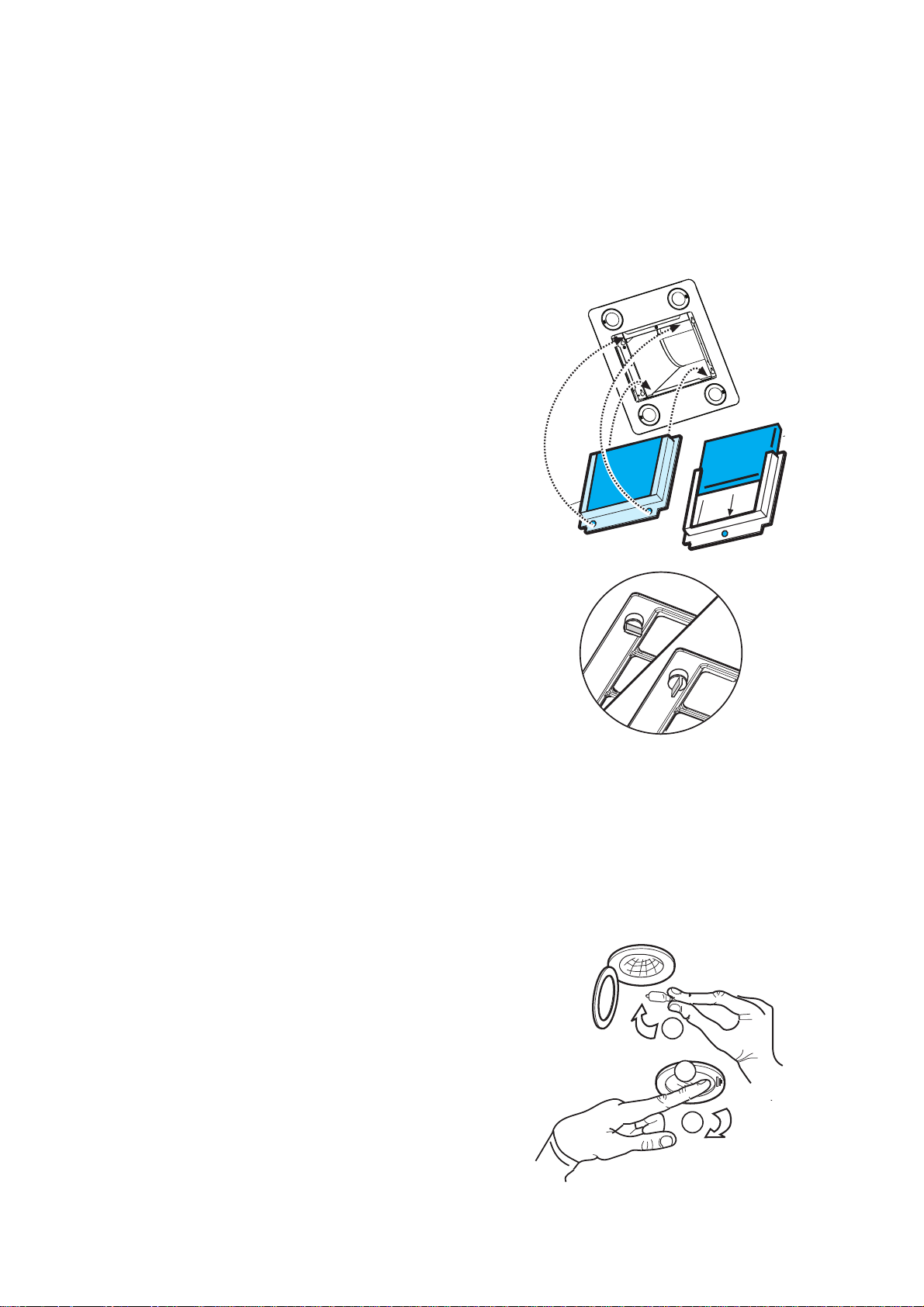
Ouverture du filtre à graisse
métallique
• Sortez la cassette du filtre à graisse métallique
et libérez le filtre en poussant vers le bas. Fig.
5.
Nettoyage à la main
• Laissez tremper la cassette du filtre à graisse
métallique durant env. 1 heure dans de l’eau
chaude avec un détergent doux puis rincez à
l’eau chaude. Remettez en place la cassette
soigneusement séchée.
Lave-vaisselle
• Placez la cassette du filtre à graisse métallique
dans le lave-vaisselle.
Vérifiez que la rotation du bras de lavage du
lave vaisselle ne puisse pas être gêné par le
filtre à graisse.
Lavez avec un programme pour vaisselles très
sales et une température d’au moins 65°C.
Recommencez éventuellement l’opération.
Remettez en place la cassette après séchage.
• Il se peut qu’il y ait quelques modifications de la
teinte de la cassette du filtre à graisse
métallique lors du passage dans le lave-vaisselle,
modifications qui n’ont aucune influence sur le
fonctionnement de la cassette.
• Nettoyez l’intérieur du logement de la casset-
te avec de l’eau chaude contenant du
détergent (n’employez jamais de détergents
corrosifs ou de brosses à récurer!).
Fig. 5
19
Page 7
Filtre à charbon
• Le filtre à charbon doit être mis en place
lorsque la hotte est utilisée en version recyclage.
• Pour cela, il faudra utiliser le filtre à charbon
actif d’origine ELECTROLUX (voir
Accessoires).
• Nettoyage/remplacement du filtre à
charbon
A la différence d’autres filtres de même type, le
filtre à charbon LONG LIFE peut être nettoyé
et réutilisé. Le filtre doit être nettoyé tous les
deux mois en utilisation normale (en
considérant une utilisation moyenne de 2,5
heures par jour). Il est recommandé de nettoyer
le filtre dans un lave-vaisselle, à la température
maximum. Utiliser un détergent normal. Aucun
ustensile ménager ne doit être présent dans le
lave-vaisselle lors du nettoyage du filtre, afin
d’éviter tout dépôt de particules d’aliments qui
risqueraient de causer ultérieurement de
mauvaises odeurs. Pour réactiver le charbon, il
suffit de mettre le filtre à sécher au four. Régler
le four sur chaleur normale, à une température
de 100°C, et y laisser le filtre pendant 10
minutes.
Le filtre doit être changé au bout de trois ans
environ, car il a alors perdu une bonne partie de
sa capacité de rétention des odeurs.
• Montage
Enlevez le châssis i qui soutient le filtre h en
tournant de 90° les boutons (g) qui le fixent à la
hotte. Introduisez le coussinet de charbon actif à
l’intérieur du châssis et remontez le tout à sa
place. Fig. 6.
• Pour le démontage, procédez dans l’ordre
inverse.
• Lors de la commande d’un filtre de rechange,
veuillez préciser la désignation du modèle et la
référence du produit. Ces données sont
indiquées sur la plaque signalétique à l’intérieur
de l’appareil.
• Vous pouvez commander le filtre à charbon
auprès de votre magasin vendeur.
g
g
Fig. 6
g
h
i
g
h
Remplacement de l´ampoule
d’éclairage
• Mettez la hotte hors tension.
• Appuyez (2) sur le diffuseur de l’ampoule et
dégrafer (1).
• Remplacez l'ampoule défectueuse par une
ampoule du même type (3).
• Refermez le diffuseur de l’ampoule (4).
• Si l'ampoule ne s'allume pas, vérifiez qu'elle est
correctement installée avant d'appeler le
Service Après-Vente.
3
1
2
Fig. 7
20
Page 8

Accessoires (en option)
Filtre à charbon KF 20 E-Nr. 942 120 600
Service Après-vente
Dans le cas de demandes de renseignement ou de pannes, veuillez appeler notre service après-vente (voir la liste
de nos différents points de service après-vente).
Lors de l’appel, préciser :
1. La désignation du modèle
2. La référence
3. Le numéro de l’appareil
Ces données sont indiquées sur la plaque signalétique située à l’intérieur de l’appareil et visible
après ouverture de la grille du filtre à graisse.
Sous réserve de modifications de construction et de coloris dans le cadre du développement technique.
Pour les appareils commercialisés en France
Si une intervention s’avère nécessaire, le vendeur de votre appareil est le premier habilité à intervenir. A défaut
(déménagement de votre part, fermeture du magasin où vous avez effectué l’achat,…) veuillez consulter
l’Assistance Consommateurs qui vous communiquera alors l’adresse d’un service après vente.
Signalez au service après vente le numéro PNC et le S-No (numéro de série), que vous trouverez sur la plaque
signalétique située sur votre appareil.
Afin de répondre rapidement, nous vous recommandons de l’inscrire à cet endroit.
PNC :
S-No :
Caractéristiques techniques
Modèle: EFC 1460 EFC 1420 EFC 1420
PNC 942 120 788 PNC 942 120 860
Dimensions (en cm):
Hauteur 85,7-113 66,4-83,1 74,5 x 83
(85,8-102,4 avec rallonge)
Largeur 99,4 100 100
Profondeur 70 70 70
Puissance nominale totale: 240 W 255 W 255 W
Puissance moteur : 1 x 170 W 1 x 175 W 1 x 175 W
Eclairage: 4 x 20 W 4 x 20 W 4 x 20 W
Longueur du câble d’alimentation: 150 cm 150 cm 150 cm
Branchement électrique 220-240 V 230 V 230 V
Nous nous réservons d’apporter toute modification en termes constructifs et chromatiques qui se révélera
nécessaire au vu de l’évolution technologique.
21
Page 9
Installation
Déballage
Vérifiez que la hotte n’est pas endommagée.
Signalez immédiatement tout dégât dû au transport
à la personne compétente et tout défaut ou manque
au fabricant.
Ne laissez pas traîner le matériel d’emballage pour
éviter que les enfants ne jouent avec lui.
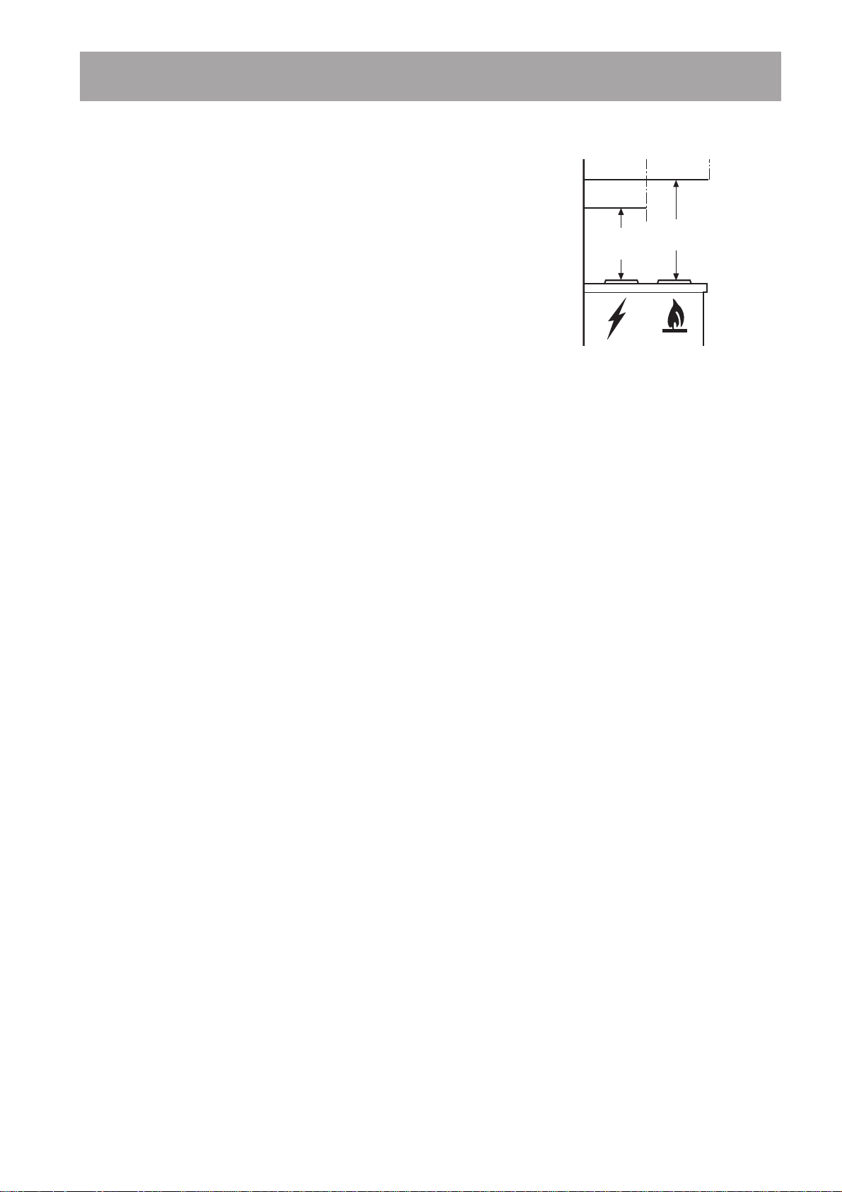
Montage
La hotte aspirante doit être montée au mur. Une
fois installée, elle doit être à au moins 50 cm des
corps de chauffe électriques et 65 cm des brûleurs
à gaz et mixtes (fig. 8).
Branchement électrique
Consignes de sécurité pour l’électricien
Avant de brancher l’appareil, vérifier que la tension
indiquée sur la plaque signalétique correspond à
celle du secteur. Si l’appareil est muni d’une fiche
de courant, il pourra être branché sur n’importe
quelle prise de courant installée conformément aux
normes et facile d’accès.
Si un branchement permanent est nécessaire, la
hotte devra être branchée par un électricien
travaillant pour une entreprise d’électricité agréée.
Côté installation, il faudra prévoir un dispositif de
protection sur tous les pôles avec une course d’ouverture de contact d’au moins 3 mm.
Notre responsabilité ne peut être engagée pour les
défauts résultants du non respect des instructions
précédemment mentionnées.
Branchement permanent uniquement par un
électricien agréé!
Min
50 cm
Min
65 cm
Fig. 8
Pour les appareils
commercialisés par la France
Branchement électrique
Votre appareil ne peut être branché qu’en 230 V
monophasé.
Vérifiez que la puissance de l’installation est
suffisante et que les lignes sont en bon état et
peuvent supporter l’intensité absorbée par
l’appareil, compte tenu des autres appareils
branchés.
Calibre des fusibles en ligne (un par phase) 10 A
en 230 V.
Important
L’installation doit être réalisée conformément aux
règles de l’art, aux prescriptions de la norme NF.C
15.100 et aux prescriptions de l’E.D.F.
Utilisez un socle de prise de courant comportant
une borne de mise à la terre, qui doit être
obligatoirement raccordée conformément à la
norme NF.C.15.100 et aux prescriptions de
l’E.D.F. ; cette prise de courant doit
impérativement être accessible.
Dans le cas où l’appareil est relié aux canalisations
électriques fixes, un dispositif de séparation
bipolaire ayant une distance d’ouverture des
contacts d’au moins 3 mm doit être prévu dans
l’installation fixe.
Le cordon secteur est à 3 conducteurs.
Si le câble d’alimentation est endommagé, il doit
être remplacé par un câble d’alimentation certifié.
Cette opération ne peut être effectuée que par une
personne habilitée, par votre vendeur, ou par le
fabricant.
L’appareil ne doit pas être raccordé à l’aide d’un
prolongateur ou d’une prise multiple.
Vérifiez que la prise de terre est conforme aux
règlements en vigueur.
Notre responsabilité ne saurait être engagée
pour tout incident ou accident provoqué par
un raccordement électrique non conforme ou
par une mise à la terre inexistante ou
défectueuse.
22
Page 10
Accessoires/Matériel de
montage
1déflecteur (3 pièces à assembler)
1clé (pour visser les vis avec tête du type
TORX)
1 manchon de réduction Ø 125-120 mm
(Seulement pour le modèle EFC 1460 X / 942
120 706)
6 vis à bois 6 x 70 mm (pour les fixations au
plafond)
5 chevilles Ø 10 mm (pour les fixations au
plafond)
10 vis à tôle 4x7 (pour assembler la cheminée)
10 écrous (pour assembler la cheminée)
10 vis à tôle 3x9 (pour assembler la structure de
support )
6 vis à tôle 4 x 8 (pour assembler la structure de
support )
Attention!
Le modèle EFC 1420avec chemin sans ouvertures
laterales est fourni sans déflecteur d’air et sans vis
de fixation.
Il est, par contre, équipé d’une rallonge pour
la structure de support ainsi que des vis
nécessaires pour la fixation.
F
G
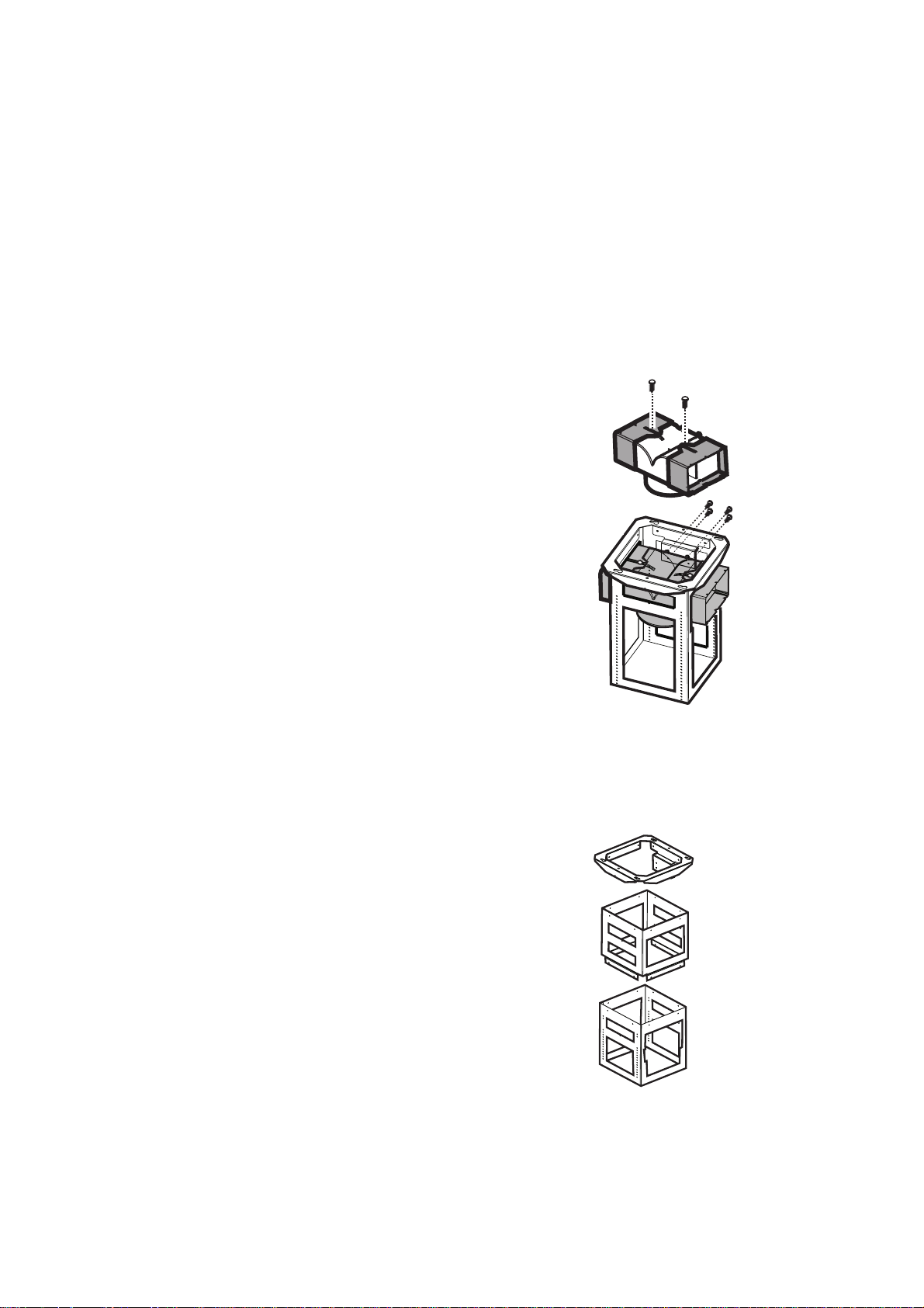
Informations préliminaires pour
l’installation de la hotte
Assembler le déflecteur (3 parties –
seulement en version recyclage):
Les trois parties doivent être fixées entre elles avec
2 vis, l’extension du déflecteur est réglable et doit
correspondre à la largeur du support cheminée
auquel il sera ensuite fixé. Fig. 9a.
Installation de la rallonge dans la structure du
support
(seulement modèle EFC1420 - PNC 942 120
788):
Dans l’éventualité où il serait nécessaire d’avoir
une structure de support plus longue (par exemple
dans le cas de plafonds particulièrement élevés), il
faut alors installer la rallonge:
• démonter la bride de la structure en enlevant
les vis de fixation (conserver les vis).
• appliquer la rallonge entre la structure e la bride
et fixer avec 16 vis. Fig. 9b.
Fig. 9a
Bride
Rallonge
Structure
Fig. 9b
23
Page 11
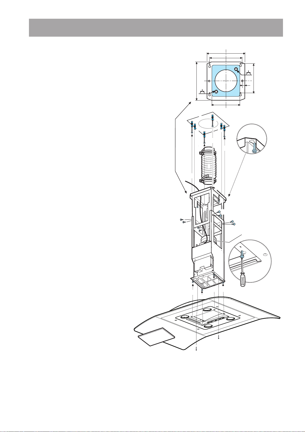
Installation
Fixation - Fig. 10-11-12
La hotte est équipée de chevilles de fixation convenant à la
plupart des plafonds. Il est cependant nécessaire de
s’adresser à un technicien qualifié afin de s’assurer que le
matériel est approprié au type de plafond. Le plafond doit
être suffisamment solide pour supporter le poids de la hotte.
Durant les phases de branchement électrique, coupez le
courant depuis le tableau principal de l’habitation.
• Réglez l’extension de la structure de support de la hotte,
la hauteur finale de la hotte dépend de ce réglage,
n’oubliez pas que la hotte, une fois installée, doit se
trouver à une distance d’au moins 50 cm. du plan de
cuisson en cas de feux électriques et à 65 cm. en cas de
feux à gaz ou mixtes.
• Fixez les deux parties de la structure avec 8 vis au total
(2).
•À la verticale du plan de cuisson, appliquez le schéma
de perçage au plafond (3 - le centre du schéma doit
correspondre au centre du plan de cuisson et les côtés
doivent être parallèles aux côtés du plan de cuisson; le
côté du schéma avec l’indication FRONT correspond au
côté du bandeau de commande). Préparez le
branchement électrique.
• Percez comme indiqué (6 orifices pour 6 chevilles
murales – 4 chevilles pour l’accrochage), vissez 4 vis
sur les orifices extérieurs en laissant un espace
d’environ 1 cm. entre la tête de la vis et le plafond (4).
• Introduisez le tuyau d’évacuation (5) à l’intérieur de la
structure et raccordez-le à la bague de raccord du
logement moteur (tuyau d’évacuation et colliers de
fixation non fournis).
• Accrochez la structure aux 4 vis (voir opération 6 et 4)
ATTENTION! Le côté de la structure avec la boîte de
connexion correspond au côté du bandeau de
commande une fois que la hotte est montée.
• Serrez à fond les 4 vis (7).
• Introduisez et vissez à fond les 2 autres vis sur les
orifices encore libres pour la fixation de sécurité (8). .
• Effectuez le raccordement électrique (9) à l’alimentation
de l’habitation, rebranchez le courant uniquement après
avoir terminé l’installation.
• Accrochez la hotte à la structure (10),
contrôlez que l’accrochage est parfait –
pour accrocher la hotte à la structure,
vissez partiellement les 4 vis (voir
operation 12).
• Fixez la hotte à la structure à l’aide de 2
vis (11), elles serviront aussi pour centrer
les deux parties.
• Serrez à fond les 4 vis qui fixent la
structure à la hotte (12).
2a
273
244
273
214
3
4
4
4
4
6
9
7
8
2a
10
10
11
4
4
6
6
5
7
7
8
7
10
2a
2a
10
11
Fig. 10
190
14,5
7
D
12
24
Page 12
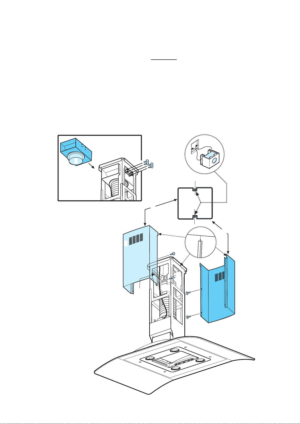
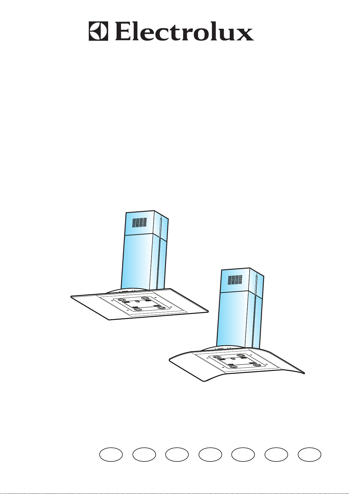
• En cas de fonctionnement en version aspirante (13A), raccordez l’autre extrémité du tuyau d’évacuation au
dispositif d’évacuation de l’habitation.
En cas de fonctionnement en version filtrante (13F), montez le déflecteur F sur la structure et fixez-le à la
bride prévue à cet effet à l’aide de 2 vis puis raccordez le tuyau d’évacuation à la bague de raccordement
située sur le déflecteur.
• Appliquez les écrous avec crochets de fixation (14)
à l’intérieur des parties supérieures et inférieures des
cheminées, en face des fentes rectangulaires. Au total, il est nécessaire de positionner 10 écrous.
• Assemblez les deux parties supérieures de la cheminée (15) de sorte qu’elles recouvrent la structure et que
les fentes présentes sur les parties soient positionnées, l’une du côté du bandeau de commande et l’autre du
côté opposé.
Vissez les deux parties à l’aide de 4 vis (2 de chaque côté – voir aussi le schéma en plan pour l’assemblage
des deux parties).
• Fixez l’ensemble cheminée supérieure à la structure, à proximité du plafond, à l’aide de deux vis (16 - une de
chaque côté).
14
F
13F
G
15
H
15
15
13A
16
15
15
15
16
15
15
25
Fig. 11
Page 13
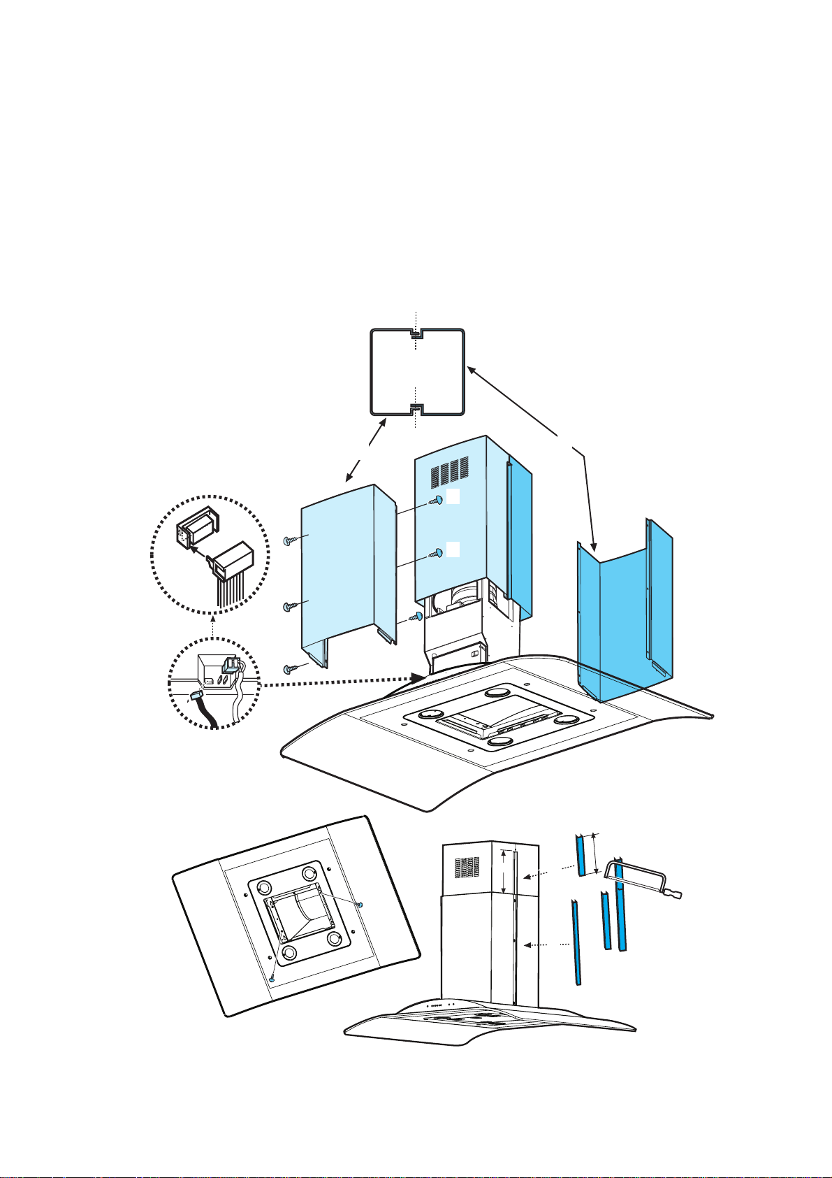
• Effectuez le raccordement électrique du bandeau de commande et des lampes (17).
• Assemblez les deux parties inférieures de la cheminée de façon qu’elles recouvrent la structure (18), utilisez
6 vis (3 de chaque côté, voir aussi schéma en plan pour l’assemblage des deux parties).
• Introduisez la partie inférieure de la cheminée dans le logement prévu à cet effet de sorte qu’elle recouvre
complètement le logement moteur et la boîte des connexions électriques, fixez à l’aide de deux vis depuis
l’intérieur de la hotte (19).
• Appliquez 2 bordures (20 - fournies) afin de recouvrir les points de fixation des parties de la cheminée
inférieure (ATTENTION! LES BORDURES DE LA CHEMINÉE INFÉRIEURE SONT
RECONNAISSABLES CAR ELLES SONT PLUS ÉTROITES ET MOINS PROFONDES).
Les bordures les plus larges et les plus profondes doivent être utilisées pour la cheminée supérieure et
coupées à la mesure désirée.
• Rebranchez le courant en intervenant sur le tableau électrique central et contrôlez le fonctionnement de la
hotte.
18
18
18
18
17
18
18
18
18
18
18
M
X
20
X
19
20
19
Fig. 12
26
Page 14

Inhoud
Veiligheidsaanwijzingen .................................................................................................................................... 28
voor de keukenmeubel-monteur .............................................................................................................................28
voor de gebruiker ................................................................................................................................................... 28
Algemeen............................................................................................................................................................ 29
Gebruik als afzuigkap .............................................................................................................................................29
Gebruik als recirculatiekap..................................................................................................................................... 29
Bediening van de afzuigkap - EFC 1460 ........................................................................................................ 30
Bediening van de afzuigkap - EFC 1420 ........................................................................................................ 31
Onderhoud .......................................................................................................................................................... 32
Reiniging ................................................................................................................................................................ 32
Metalen vetfilters ................................................................................................................................................... 32
Demonteren van de metalen vetfilters ................................................................................................................... 32
Koolfilter ................................................................................................................................................................ 33
Vervangen van de lamp(en) ...................................................................................................................................33
Extra leverbare accessoires ............................................................................................................................ 34
NL
Klantenservice ................................................................................................................................................... 34
Technische gegevens........................................................................................................................................ 36
Installatie ............................................................................................................................................................ 36
Uitpakken ............................................................................................................................................................... 36
Elektrische aansluiting ............................................................................................................................................36
Toebehoren/Montagemateriaal .............................................................................................................................. 37
Voorbereidende maatregelen voor de installatie .................................................................................................... 37
Montage .................................................................................................................................................................38
Voordat u uw nieuwe afzuigkap in gebruik neemt, dient u eerst deze gebruiks- en installatie-aanwijzing door te
lezen.
Om gevaren die het gebruik van elektrische apparaten met zich meebrengt te voorkomen, is het belangrijk dat de
kap correct wordt geïnstalleerd en dat u de veiligheidsvoorschriften opvolgt. Houd de gebruiksaanwijzing bij de
hand, zodat u nog eens iets kunt nalezen.
27
Page 15

Veiligheidsaanwijzingen
voor de keukenmeubel-monteur
• De afvoerbuis moet bij gebruik als afzuigkap
een diameter van 150 mm hebben.
Alleen voor model EFC 1460 X / 942 120
706:
Als een afvoerbuis in wand of dak met een
diameter van 125 mm al aanwezig is, kan het
meegeleverde verloopstuk, 150/125 mm, worden
gebruikt.
• Indien nodig zijn op bestelling buizen in
verschillende vormen en diameters en
afvoersystemen naar buiten (telescoop-
muurkast) verkrijgbaar. Neem daarvoor contact
op met onze service-afdeling.
• Bij de montage van de afzuigkap moeten
de volgende minimale afstanden van de
bovenkant van de kookzones of
gasbranders tot de onderkant van de
afzuigkap worden aangehouden:
elektrisch fornuis 500 mm
gasfornuis 650 mm
kolen- en oliefornuis min. 700 mm
• Bij gelijktijdig gebruik van het apparaat als
afzuigkap en stookplaatsen mag in de ruimte
waar de stookplaats zich bevindt de onderdruk
niet groter dan 4PA (4x10
• De afgewerkte lucht mag niet in een kanaal dat
bestemd is voor de afvoer van rook-/
verbrandingsgassen of een schacht die dient
voor de ontluchting van ruimten met
stookplaatsen geleid worden.
• Voor het afvoeren van de afgewerkte lucht
moeten de plaatselijke voorschriften in acht
genomen worden.
• Bij gebruik als afzuigkap moet gezorgd worden
voor een voldoende grote toevoeropening, die
ongeveer even groot als de afvoeropening moet
zijn.
• Op grond van landelijke bouwvoorschriften
gelden voor het gemeenschappelijk gebruik van
afzuigkappen en toestellen die zijn aangesloten
op een verbrandingsgaskanaal/schoorsteen,
zoals kolen - of oliekachels en gasovens in
dezelfde ruimte, bepaalde beperkingen.
• Het gemeenschappelijke, ongevaarlijke gebruik
van schoorsteengebonden toestellen en
afzuigkappen is alleen gewaarborgd, als ruimte
en/of woning door een geschikte toevoeropening
van ca. 500-600 cm2 van buiten geventileerd
zijn, waardoor bij lopende afzuigkap een
onderdruk vermeden wordt.
-5
bar) zijn.
• Omdat in ruimten zonder rookkanaalafvoer de
regel geldt “toevoeropening even groot als
afvoeropening” kan door de grotere opening van
500-600 cm
nadelig beïnvloed worden.
• Het gebruik van het apparaat als recirculatiekap
is onder de genoemde omstandigheden zonder
gevaar en valt niet onder bovengenoemde
voorschriften.
• Het apparaat functioneert als afzuigkap alleen
optimaal als u het volgende in acht neemt:
- korte, rechte afvoerverbindingen
- zo min mogelijk bochten in de buis
- buizen niet met scherpe hoeken maar met
- zo groot mogelijke buisdiameter (bij
• Als u deze basisregels niet in acht neemt, moet
u rekening houden met aanzienlijk
vermogensverlies en verhoogd bedrijfsgeluid.
2
de werking van de afvoerinrichting
flauwe bochten laten verlopen
voorkeur dezelfde diameter als de
afvoeropening).
voor de gebruiker
• U dient erop te letten dat op ingeschakelde
kookzones en gasbranders altijd een pan staat,
opdat het apparaat niet door te sterke hitteontwikkeling wordt beschadigd. Bij olie-, gas- en
kolenfornuizen dient open vuur beslist te worden
vermeden.
• Bovendien moet bij het frituren op een fornuis
of kookplaat de frituurpan tijdens het gebruik
altijd in het oog worden gehouden.
• De olie in de frituurpan kan door oververhitting
vlam vatten.
• Bij gebruik van verontreinigde olie kan nog
makkelijker zelfontbranding ontstaan.
• Wij wijzen u erop dat door oververhitting brand
kan ontstaan.
• Flamberen onder de afzuigkap is niet
toegestaan.
• Bij alle werkzaamheden aan de afzuigkap, ook
bij het vervangen van de lamp, moet het
apparaat spanningloos worden gemaakt
(zekering in de huisinstallatie uitschakelen).
• Het is belangrijk dat u tijdig de filters vervangt
resp. reinigt.
Anders bestaat ten gevolge van vetafzetting
brandgevaar.
28
Page 16

Algemeen
D
• Het apparaat wordt als afzuigkap geleverd en
kan in combinatie met een koolfilter (extra
leverbaar accessoire) als recirculatiekap
worden gebruikt.
• Daarvoor is een origineel ELECTROLUX
koolfilter nodig (zie “Extra leverbare
accessoires”).
Gebruik als afzuigkap
• De lucht wordt met behulp van een op de
afvoeropening aan te brengen buis naar buiten
afgevoerd. Afb. 1.
• Voor de beste afzuigprestaties moet de
afvoerbuis dezelfde diameter hebben als de
afvoeropening.
• Indien nodig zijn op bestelling buizen in
verschillende vormen en diameters en
afvoersystemen naar buiten (telescoopmuurkast) verkrijgbaar. Neem daarvoor contact
op met onze service-afdeling.
Afvoeropening
afb. 1
Gebruik als recirculatiekap
• De lucht wordt door koolfilters gefilterd en weer
de keuken in geleid.
• Voor gebruik als recirculatiekap is een origineel
ELECTROLUX koolfilter KF20 (extra
leverbaar accessoire) nodig.
• De luchtgeleider met 4 schroeven Ø 3,5x13 mm
bevestigen. Afb. 2.
Let op!
Model EFC 1420 met schouw zonder
openingen aan de zijkant is niet uitgerust met
luchtgeleider en bevestigingsschroeven .
F
afb. 2
29
Page 17

Bediening van de afzuigkap - EFC 1460
• De afzuigkap is voorzien van een motor met
regelbaar toerental. Wij raden u aan de kap
enkele minuten voordat u met koken begint in te
schakelen en ca. 15 minuten nadat u klaar bent
met koken verder te laten lopen, opdat alle
luchtjes worden verwijderd. De schakelaars
bevinden zich aan de voorkant van de kap:
• Licht : Hiermee kan de verlichting van de
afzuigkap worden in- en uitgeschakeld.
• Toets ON/OFF/Stand 1: Deze knop dient om
de kap in of uit te schakelen en om stand 1 te
kiezen.
• Stand 2 : Deze knop dient om stand 2 te
kiezen.
• Stand 3 : Deze knop dient om stand 3 te
kiezen.
Ventilatie
Voor een goede werking van de kap moeten
ramen in de keuken tijdens het koken gesloten
zijn. In plaats daarvan moet de keukendeur
open staan en is het wenselijk om een raam in
een aangrenzend vertrek open te zetten.
Lichtknop
Toets ON/OFF/
Stand 1
Stand 2
afb. 3
Stand 3
30
Page 18

Bediening van de afzuigkap - EFC 1420
• De afzuigkap is voorzien van een motor met regelbaar toerental. Wij raden u aan de kap enkele minuten
voordat u met koken begint in te schakelen en ca. 15 minuten nadat u klaar bent met koken verder te laten
lopen, opdat alle luchtjes worden verwijderd. De schakelaars bevinden zich aan de voorkant van de kap:
ABCDEFGH I
afb. 4
Controle-inrichting voor vet- en
A - uitschakelen
B - inschakelen en stand 1-2-3- kiezen
C - indicatie stand 1 (LED)
D - indicatie stand 2 en vetfilter verzadigd
(LED) (lampje knippert)
E - indicatie stand 3 en koolfilter verzadigd
(LED) (lampje knippert)
F - indicatie intensief-stand (LED)
G - inschakelen intensief-stand:
na 5 minuten intensief-stand schakelt de
kap op de eerder ingestelde stand terug
resp. uit, als geen stand is ingesteld. Om
de intensief-stand eerder te beëindigen,
knop A of B indrukken.
H - uitschakelen verlichting
I - inschakelen verlichting
Als het apparaat of de bedieningselementen niet
functioneren: minstens 5 seconden de
stroomverzorging naar de kap onderbreken en dan
opnieuw inschakelen.
koolfilters
Deze afzuigkap beschikt over een inrichting die
aangeeft wanneer de vetfilters resp. het koolfilter
gereinigd moeten worden (bij gebruik als
recirculatiekap met koolfilter).
Deze kap wordt door de fabriek zonder koolfilter
geleverd, daarom is de verzadigingsindicatie voor
het koolfiter uitgeschakeld.
Als de kap echter met koolfilter in gebruik wordt
genomen, dan moet deze verzadigingsindicatie als
volgt worden ingeschakeld:
Toets B en G tegelijk 3 seconden ingedrukt houden.
Eerst gaat alleen de LED-indicatie vetfilter D
branden. Zodra ook de LED-indicatie koolfilter E
gaat branden is de verzadigingsindicatie
ingeschakeld.
Om de indicatie uit te schakelen: toets B en G
tegelijk 3 seconden ingedrukt houden tot de LEDindicatie koolfiter E uitgaat.
LED-indicatie vetfilters (D)
De LED-indicatie D knippert als de vetfilters
moeten worden gereinigd. Dat is na ca. 40
gebruiksuren het geval. Zie hoofdstuk “Onderhoud
- Metalen vetfilters”.
LED-indicatie koolfilter (E)
De LED-indicatie E knippert als het koolfilter moet
worden gereinigd. Dat is na ca. 160 gebruiksuren
het geval. Zie hoofdstuk “Onderhoud - Koolfilter”.
Reset verzadigingsindicatie
Na reinigen van de vetfilters resp. van het koolfilter
toets A 3 seconden ingedrukt houden tot de LEDindicatie vetfilter D of koolfilter E niet meer
knippert.
31
Page 19

Onderhoud
• Voordat u werkzaamheden aan het apparaat gaat uitvoeren, eerst de stekker uit het stopcontact
trekken.
Reiniging
• Attentie: eerst de stekker uit het stopcontact
trekken.
Geen spitse voorwerpen in het beschermrooster
van de motor steken.
• De buitenkant van het apparaat met een mild
sopje reinigen. Gebruik geen scherpe
reinigingsmiddelen, borstels of schuurmiddel.
• Het bedieningspaneel en het vetfilterrooster
alleen met een vochtige doek en mild
afwasmiddel reinigen.
• Het is belangrijk om op tijd de filters te
vervangen resp. te reinigen. Als u deze
aanwijzingen niet opvolgt, kan t.g.v. vetafzetting
brandgevaar ontstaan.
Metalen vetfilters
Attentie
• Als u deze aanwijzingen m.b.t. reiniging van het
apparaat en vervanging resp. reiniging van de
filters niet opvolgt, kan dat tot brand leiden.
Deze aanwijzingen beslist opvolgen!
• De fabrikant is niet aansprakelijk voor schade
aan de motor of schade t.g.v. brand die het
gevolg zijn van ondeskundig onderhoud of niet
opvolgen van de bovengenoemde
veiligheidsvoorschriften.
• De metalen vetfilters hebben de taak om de
vetdeeltjes die bij het koken ontstaan, op te
zuigen en worden altijd, d.w.z. zowel bij gebruik
als afzuigkap als bij gebruik als recirculatiekap,
gebruikt.
De metalen vetfilters moeten elke 4 weken
worden gedemonteerd en in de afwasautomaat
of met de hand worden schoongemaakt.
Demonteren van de metalen
vetfilters
• Schuif de vergrendeling van de metalen
vetfilters eerst naar voren en trek de cassette
dan naar beneden, afb. 5.
Reinigen met de hand
Metaalfiltercassette ca. 1 uur in heet water met
een vetoplossend schoonmaakmiddel weken en
daarna met heet water afspoelen. Proces evt.
herhalen. Cassette afdrogen en weer inzetten.
Afwasautomaat
Metaalfiltercassette in de afwasautomaat
zetten. Sterkste programma en hoogste
temperatuur (min. 65°C) kiezen. Proces evt.
herhalen. Cassette afdrogen en weer inzetten.
Machinaal reinigen van de metalen
vetfilters kan tot lichte verkleuringen
leiden, die echter geen invloed op de
werking hebben.
• De binnenkant van de kap alleen met een warm
sopje reinigen. Geen scherpe reinigingsmiddelen,
borstels of schuurmiddelen gebruiken!
afb. 5
32
Page 20

Koolfilter
• Het koolfilter moet worden gebruikt, als het
apparaat als recirculatiekap wordt gebruikt.
• Daarvoor is een origineel ELECTROLUX
koolfilter nodig (zie “Extra leverbare
accessoires”).
• Reinigen/vervangen van het koolfilter
In tegenstelling tot andere koolfilters kan het
LONG LIFE koolfilter gereinigd en
gereactiveerd worden. Bij normaal gebruik van
de kap moet het filter eens per twee maanden
worden gereinigd (voor een gemiddeld gebruik
van de kap van 2,5 uur per dag).
Dat kunt u het beste in de afwasautomaat doen.
Normaal reinigingsmiddel gebruiken en de
hoogste temperatuur kiezen (65°C). Het filter
moet apart worden afgewassen, opdat zich geen
etensresten op het filter vastzetten die later nare
luchtjes kunnen veroorzaken. Om de kool weer
te activeren, moet het filter in de oven worden
gedroogd. Boven- en onderwarmte en een
temperatuur van maximaal 100°C kiezen en het
filter 10 minuten lang drogen.
Na ca. 3 jaar moet het filter worden vervangen,
omdat dan het vermogen om wasem op te
nemen ca. 50% minder is geworden.
• Montage
Het frame i van het filter h losnemen: daartoe
de vergrendelingen g 90° draaien. Koolfilter in
het frame zetten en in omgekeerde volgorde
weer bevestigen. Afb. 6.
• Om het filter los te nemen in omgekeerde
volgorde te werk gaan.
• Bij bestelling van een nieuw filter modelnaam en
E-nr. opgeven. Deze gegevens vindt u op het
typeplaatje aan de binnenzijde van het apparaat.
• Het koolfilter kunt u bestellen bij de serviceafdeling van ELECTROLUX.
g
g
afb. 6
g
h
i
g
h
Vervangen van de lamp(en) - afb. 7
• Stekker uit het stopcontact trekken.
• Afdekkapje (2) van de lamp indrukken (1) en
openen.
• Defecte lamp door een gelijkwaardige lamp
vervangen (3).
• Afdekplaatje weer sluiten.
• Voordat u contact opneemt met onze service-
afdeling, omdat de gloeilamp niet brandt, eerst
controleren of de lamp stevig vast zit.
3
1
2
afb. 7
33
Page 21

Extra leverbare accessoires
koolfilter KF20 E-Nr. 942 120 600
muurkast Neem contact op met
onze service-afdeling
afvoerbuis Neem contact op met
onze service-afdeling
Klantenservice
Als u vragen hebt waar deze gebruiksaanwijzing geen antwoord op geeft, kunt u de volgende afdelingen
raadplegen:
Consumentenbelangen
(voor algemene, product- of tel. (0172) 468 172
gebruiksinformatie) fax. (0172) 468 470
Storingen / reparaties
(voor bezoek servicetechnicus) tel. (0172) 468 300
fax. (0172) 468 255
Belangrijk!
Houd bij het opgeven van een storing altijd modelaanduiding, E-nummer en F-nummer van uw apparaat bij de
hand. Deze nummers vindt u op de binnenzijde van de afzuigkap, nadat u de vetfilters hebt losgenomen en kunt u
het beste hieronder noteren.
modelaanduiding ........
E-nr. ......
F-nr. ......
Bereid het gesprek altijd goed voor. Zo vergemakkelijkt u de diagnose en de beslissing of bezoek van een
servicetechnicus nodig is.
Geef zo nauwkeurig mogelijk op:
- Hoe doet de storing zich voor?
- Onder welke omstandigheden treedt de storing op?
Aan de hand van deze informatie kan onze service-afdeling de juiste
voorbereidingen treffen, zodat het apparaat bij het eerste bezoek van de
servicetechnicus weer hersteld kan worden. Op deze manier hoeft u slechts één maal thuis te blijven.
Constructie- en kleurwijzigingen in het kader van de technische ontwikkeling voorbehouden.
34
Page 22

Reparatievoorwaarden
Onze reparatievoorwaarden zijn conform de afspraak tussen de
Consumentenbond en Vlehan*.
Art. 1 Aan de consument zal na een melding van een storing zo mogelijk direct, doch uiterlijk binnen één werkdag worden medegedeeld
op welke dag het bezoek van de technicus zal plaatsvinden.
De reparatie zal als regel binnen zeven werkdagen na de melding zijn uitgevoerd.
Art. 2 a) Alvorens de reparatie wordt verricht zal de technicus een onderzoek uitvoeren naar de vermoedelijke oorzaak van de gemelde
storing. Aan de hand hiervan zal hij een zo nauwkeurig mogelijke, gespecificeerde begroting maken van de totale reparatiekosten
inclusief voorrijkosten en diagnose-kosten.
Desgevraagd zal deze begroting door de technicus schriftelijk worden vastgelegd.
b) Indien de consument met het begrote bedrag niet akkoord gaat, zal op verzoek het te repareren toestel worden teruggebracht in
de staat waarin het aan de technicus werd aangeboden. Nadat dit is geschied, zullen alleen de kosten van voorrijden en arbeidsloon
in rekening worden gebracht op basis van de werkelijke bestede tijd, danwel van een vooraf vastgesteld tarief.
Art. 3 Indien tijdens het uitvoeren van de reparatie duidelijk wordt dat:
a) de oorspronkelijke reparatie door redelijkerwijs niet te voorziene omstandigheden niet tegen het begrote bedrag kan worden
uitgevoerd, of
b) ook andere dan in de begroting voorziene reparaties noodzakelijk zijn, zal overleg met de consument plaatsvinden en een
herziene kostenbegroting worden gemaakt.
In geval de consument daarmee alsnog niet akkoord gaat, geldt eveneens het in artikel 2b bepaalde.
Art. 4 De reparatie zal zoveel mogelijk tijdens het eerste bezoek worden uitgevoerd. Indien om het toestel in werkende staat te brengen
een tweede bezoek noodzakelijk is, zal:
a) direct, doch uiterlijk binnen één werkdag door de betreffende service-organisatie of door de technicus met de consument de
datum voor een tweede bezoek worden afgesproken.
b) een herhalingsbezoek zal als regel binnen tien werkdagen na de melding plaatsvinden.
c) voor een tweede of daaropvolgend bezoek zal geen voorrijtarief in rekening worden gebracht, tenzij de noodzaak voor een
herhalingsbezoek aan de consument is toe te schrijven.
Art. 5 De consument ontvangt een gespecificeerde rekening met vermelding van type en serienummer van het apparaat, omschrijving van
de diagnose, toegepaste tarieven, gebruikte onderdelen en materialen en een korte omschrijving van de verrichte werkzaamheden.
De betaling van de rekening dient tegen afgifte van een reparatienota direct contant of door middel van een gegarandeerd
betaalmiddel plaats te vinden.
Art. 6 Op elke uitgevoerde en betaalde reparatie zal bij normaal huishoudelijk gebruik een volledige garantie van minimaal 3 maanden
worden gegeven. Deze garantie omvat het kosteloos uitvoeren van een hernieuwde reparatie. Op de uitgewisselde en betaalde
onderdelen geldt een garantietermijn van 12 maanden.
Bij een beroep op garantie op de reparatie dient de consument op verzoek de gespecificeerde rekening van de voorgaande reparatie
aan de technicus te overleggen.
Art. 7 Indien na driemaal uitvoeren van eenzelfde reparatie hetzelfde defect bij normaal huishoudelijk gebruik opnieuw optreedt binnen
de onder art. 6 bedoelde garantietermijn en redelijkerwijs een afdoend resultaat bij het opnieuw uitvoeren van de reparatie niet
verwacht kan worden, zal aan de consument een nieuw exemplaar of soortgelijk toestel van hetzelfde merk worden aangeboden
tegen bijbetaling op basis van een per product te bepalen jaarlijks afschrijvingspercentage.
Art. 8 Vervangen onderdelen stelt de technicus weer ter beschikking van de consument, met uitzondering van de onder garantie of tegen
een gereduceerde prijs vervangen onderdelen.
Art. 9 Een reparatie dient op zodanige wijze te worden uitgevoerd, dat een toestel daarna weer volledig voldoet aan de
veiligheidsvoorschriften, die op grond van een van fabriekswege aangebracht veiligheidskeurmerk gelden, danwel bij het ontbreken
daarvan, aan de wettelijke vereisten terzake.
Dit houdt ondermeer in, dat reparaties moeten worden uitgevoerd met originele en door de fabrikant ook terzake van
veiligheidskeurmerken en -voorschriften gegarandeerde onderdelen.
* Vereniging Leveranciers van Huishoudelijke Apparaten in Nederland.
35
Page 23

Technische gegevens
Model: EFC 1460 EFC 1420 EFC 1420
PNC 942 120 788 PNC 942 120 860
Afmetingen (in cm):
Hoogte 85,7-113 75-102 74,5 x 83
(85,8-102,4 met verlengstuk)
Breedte 99,4 99,8 100
Diepte 70 70 70
Totale aansluitwaarde: 240 W 255 W 255 W
Ventilatormotor: 1 x 170 W 1 x 175 W 1 x 175 W
Verlichting: 4 x 20 W 4 x 20 W 4 x 20 W
Lengte van het aansluitsnoer: 150 cm 150 cm 150 cm
Elektrische aansluiting: 220-240 V 230 V 230 V
Constructie- en kleurwijzigingen in het kader van de technische ontwikkeling voorbehouden.
Installatie
Uitpakken
Overtuig u ervan dat de afzuigkap compleet en
niet beschadigd is. Meld ontbrekend materiaal of
schade direct aan uw leverancier. Laat kinderen
niet met het verpakkingsmateriaal spelen.
Plaats
Bij de montage moet tussen de onderkant van de
kap en de bovenkant van het fornuis een afstand
van min. 50 cm (elektrisch fornuis) resp. 65 cm
(gasfornuis) worden aangehouden. Afb 8.
Elektrische aansluiting
Veiligheidsaanwijzingen voor de elektroinstallateur
Controleer vóór het in gebruik nemen of de
spanning op het typeplaatje overeenkomt met de
netspanning. Als het apparaat is voorzien van een
stekker, kan het aan elk volgens de voorschriften
geïnstalleerd en goed bereikbaar stopcontact
worden aangesloten. Als vaste aansluiting
noodzakelijk is, mag het apparaat alleen door een
erkend elektro-installateur worden aangesloten. In
de elektrische installatie moet een inrichting zijn
aangebracht die het mogelijk maakt om met een
contactopening van min. 3 mm alle polen van het
net te scheiden. Voor storingen die het gevolg zijn
van niet opvolgen van bovengenoemde
aanwijzingen is de fabrikant niet aansprakelijk.
Vaste aansluiting alleen door een erkend elektroinstallateur!
afb. 8
Min
50 cm
Min
65 cm
36
Page 24

Installatie
Toebehoren/Montagemateriaal
1 luchtgeleider (3 te monteren onderdelen)
1 sleutel om de schroeven (type TORX) vast te
draaien
1 verloopstuk Ø 125-120 mm (Alleen voor model
EFC1460 X / 942 120 706)
6 houtschroeven 6 x 70 mm (voor de bevestiging
aan het plafond)
6 pluggen Ø 10 mm (voor de bevestiging aan het
plafond)
10 plaatschroeven 4x7 (om het schouwdeel te
bevestigen)
10 moeren (om het schouwdeel te bevestigen)
10 plaatschroeven 3x9 (om het geraamte te
bevestigen)
6 plaatschroeven 4 x 8 (om de kap te bevestigen)
Let op!
Model EFC 1420 met schouw zonder
openingen aan de zijkant is niet uitgerust met
luchtgeleider en bevestigingsschroeven .
Het is wel uitgerust met een verlengstuk
voor het geraamte en schroeven voor de
bevestiging.
F
G
Voorbereidende maatregelen
voor de installatie
Luchtgeleider monteren (3 delen - alleen bij
gebruik als recirculatiekap):
De drie delen moeten met 2 schroeven aan elkaar
bevestigd worden, de maat van de luchtgeleider is
regelbaar en moet overeenkomen met de breedte
van de montagesteun waaraan hij wordt bevestigd.
Afb. 9a.
Installatie van het verlengstuk van het
geraamte (alleen model EFC1420 - PNC 942
120 788):
Indien een langer geraamte nodig is (bijvoorbeeld in
het geval van bijzonder hoge plafonds) het
verlengstuk monteren:
• demonteer de flens van het geraamte door de
bevestigingsschroeven te verwijderen (bewaar
de schroeven).
• plaats het verlengstuk tussen het geraamte
en de flens en bevestig dit met 16
schroeven. Afb. 9b.
afb. 9a
Flens
Verlengstuk
Geraamte
37
afb. 9b
Page 25

Installatie
Montage - afb. 10-11-12
De kap is voorzien van bevestigingspluggen die geschikt zijn
273
244
voor de meeste plafonds. Toch moet contact opgenomen
worden met een erkend installateur om er zeker van te zijn
dat de materialen geschikt zijn voor uw type plafond. Het
plafond moet bovendien stevig genoeg zijn om het gewicht
273
van de kap te houden.
Tijdens de montage van het apparaat mag het niet aan het
stroomnet aangesloten zijn.
214
• De gewenste lengte van het draaggeraamte van de kap
instellen. Van deze instelling hangt de definitieve hoogte
van de kap af. Let er daarbij op dat de kap na de
installatie bij elektrische fornuizen minstens 50 en bij
gasfornuizen minstens 65 cm van de bovenkant van het
fornuis verwijderd moet zijn.
• De twee delen van het geraamte met in totaal acht
3
4
4
4
4
4
4
6
6
schroeven vastzetten (2).
• Loodrecht op de kookplaat het boorsjabloon op het
plafond aanbrengen (3 - het midden van het sjabloon moet
overeenkomen met het midden van de kookplaat en de
zijkanten moeten parallel lopen met de zijkanten van de
kookplaat; de kant van het sjabloon met het opschrift
FRONT komt overeen met de kant van de
bedieningselementen). De elektrische aansluiting maken.
• De aangegeven gaten boren (zes gaten voor zes
6
9
7
5
7
7
8
7
8
2a
wandpluggen – vier pluggen voor het ophangen) en vier
schroeven zodanig in de buitenste gaten draaien, dat
tussen schroefkop en plafond een afstand van ca. 1 cm
lijft (4).
2a
2a
2a
D
• Een afvoerbuis in het geraamte (5) schuiven en met de
flens van de ventilatoruitlaat verbinden (afvoerbuis en
bevestigingsringen niet meegeleverd).
• Het draaggeraamte aan de vier plafondschroeven hangen
(6 - zie ook 4).
ATTENTIE! De geraamtekant met de aansluitbus komt
overeen met de bedieningskant van de gemonteerde kap.
• De vier schroeven (7) stevig vastdraaien.
• In de vier vrij gebleven gaten (8) als extra beveiliging nog
twee schroeven aanbrengen en stevig
10
10
10
10
vastdraaien.
• De kap aansluiten (9), maar het stroomnet
pas na de montage inschakelen.
• De kap aan het draaggeraamte hangen (10)
en controleren of hij goed op z’n plek zit:
- om de kap op te hangen vier schroeven
iets indraaien (zie 10 en 12).
• De kap aan het geraamte bevestigen met
twee schroeven (11) die later ook voor het
11
11
afb. 10
centreren van de beide delen nodig zijn.
• De vier schroeven waarmee de kap aan het draaggeraamte bevestigd is (12) stevig vastdraaien.
190
14,5
7
12
38
Page 26

• Bij gebruik als afzuigkap (13A) het andere eind van de afvoerbuis aan de afvoerinstallatie in de woning
aansluiten.
Bij gebruik als recirculatiekap met koolfilter (13F) luchtgeleider F aan het rooster monteren en met vier
schroeven aan de daarvoor bedoelde beugel bevestigen. Ten slotte de afvoerbuis met de luchtgeleider
verbinden.
• De meegeleverde moeren met bevestigingshaken (14) binnenin de bovenste en onderste schouwdelen ter
hoogte van de rechthoekige ogen aanbrengen. In totaal moeten tien moeren worden gemonteerd.
• De beide bovenste schouwdelen voor afdekking van het geraamte (15) zo in elkaar zetten dat één van de
anwezige sleuven aan de kant van de bedieningselementen en de andere aan de tegenovergestelde kant zit.
De beide delen met vier schroeven (twee per kant - zie ook schema voor de montage van de beide delen)
vastschroeven.
• De bovenste schouw in de buurt van het plafond met twee schroeven (16, één per kant) aan het geraamte
bevestigen.
• De elektrische aansluiting van het bedieningspaneel en de controlelampjes uitvoeren (17).
14
F
13F
G
15
H
15
15
13A
16
15
15
15
16
15
15
39
afb. 11
Page 27

• De beide onderste schouwdelen voor afdekking van het geraamte (18) in elkaar zetten; daarvoor zes
schroeven gebruiken (drie per kant - zie ook het schema voor de koppeling van de twee delen).
• Het onderste deel van de schouw zo plaatsen dat het de motorruimte en de verbindingsdoos volledig afdekt en
met twee schroeven vanuit het binnenste van de kap bevestigen (19).
• Met twee profielen (20 - meegeleverd) de bevestigingspunten van de delen van de onderste schouw afdekken
(ATTENTIE! DE PROFIELEN VOOR DE ONDERSTE SCHOUW ZIJN TE HERKENNEN AAN HET
FEIT DAT ZE SMALLER EN PLATTER ZIJN). De bredere profielen zijn daarentegen voor de bovenste
schouw bedoeld en worden op maat gesneden.
• Met de hoofdschakelaar van de huisinstallatie de stroom weer inschakelen en controleren of de kap goed
functioneert.
18
18
18
18
17
18
18
18
18
18
18
M
X
20
X
19
20
19
afb. 12
40
Page 28

Contents
Safety warnings.................................................................................................................................................. 42
For the installer ..................................................................................................................................................... 42
For the user ...........................................................................................................................................................42
Description of the Appliance .......................................................................................................................... 43
Extractor version................................................................................................................................................... 43
Filter Version ......................................................................................................................................................... 43
Control Panel - EFC 1460 ............................................................................................................................... 43
Control Panel - EFC 1420 ............................................................................................................................... 44
Maintenance and care ...................................................................................................................................... 45
Cleaning the hood ................................................................................................................................................. 45
Metal grease filter ................................................................................................................................................. 45
Removing the metal grease filter ..........................................................................................................................45
Charcoal filter ....................................................................................................................................................... 46
Changing the light bulb .......................................................................................................................................... 46
UK
What to do if ...................................................................................................................................................... 47
Special accessories*......................................................................................................................................... 47
Technical assistance service........................................................................................................................... 48
Service and spare parts for UK ...................................................................................................................... 48
Technical Specifications ................................................................................................................................... 48
Installation ......................................................................................................................................................... 49
Unpacking .............................................................................................................................................................49
Placement ............................................................................................................................................................. 49
Electrical connection ............................................................................................................................................. 49
Mounting accessories included ............................................................................................................................. 50
Preliminary information for installing the hood ......................................................................................................50
Mounting ............................................................................................................................................................... 51
Before you use the cooker hood we recommend that you read through the whole user manual giving a direct
description of the cooker hood and its functions.
To avoid the risks, that are always present when you use a product driven by electricity, it is important that the
cooker hood is installed correctly and that you read the safety instructions carefully to avoid misuse and hazard.
Save the instruction manual and keep it available at use of the cooker hood
41
Page 29

Safety warnings
For the installer
• When used as an extractor unit, the hood must
be fitted with a 150mm diameter hose.
Only for model EFC 1460 X / 942 120 706:
Should there already be a pipe of diameter 125
mm that ducts to the outside through the walls
or roof, it is possible to use the 150/125 mm
reduction flange provided. In this case the hood
will be slightly noisier.
• When installing the hood, make sure you
respect the following minimum distance
from the top edge of the cooking hob/ring
surfaces:
electric cookers 500 mm
gas cookers 650 mm
coal and oil cookers 700 mm min.
• The national Standard on fuel-burning systems
specifies a maximum depression of 0.04 mbar in
such rooms.
• The air outlet must not be connected to chimney
flues or combustion gas ducts. The air outlet
must under no circumstances be connected to
ventilation ducts for rooms in which fuel-burning
appliances are installed.
• The air outlet installation must comply with the
regulations laid down by the relevant authorities.
• When the unit is used in its extractor version, a
sufficiently large ventilation hole must be
provided, with dimensions that are approxi-
mately the same as the outlet hole.
• National and regional building regulations
impose a number of restrictions on using hoods
and fuel-burning appliances connected to a
chimney, such as coal or oil room-heaters and
gas fires, in the same room.
• Hoods can only be used safely with appliances
connected to a chimney if the room and/or flat
(air/environment combination) is ventilated from
outside using a suitable ventilation hole approxi-
mately 500-600 cm
possibility of a depression being created during
operation of the hood.
• If you have any doubts, contact the relevant
controlling authority or building inspector’s
office.
• Since the rule for rooms with fuel burning
appliances is “outlet hole of the same size as the
ventilation hole”, a hole of 500-600 cm2, which
is to say a larger hole, could reduce the perfor-
mance of the extractor hood.
• If the hood is used in its filtering function, it will
operate simply and safely in the above
2
large to avoid the
conditions without the need for any of the
aforementioned measures.
• When the hood is used in its extractor function,
the following rules must be followed to obtain
optimal operation:
— short and straight outlet hose
— keep bends in outlet hose to a minimum
— never install the hoses with an acute angle,
they must always follow a gentle curve.
— keep the hose as large as possible
(preferably the same diameter as the
outlet hole).
• Failure to observe these basic instructions will
drastically reduce the performance and increase
the noise levels of the extractor hood.
For the user
• The cooker hood is designed to extract
unpleasant odours from the kitchen, it will not
extract steam.
• Always cover lighted elements, to prevent
excess heat from damaging the appliance. In
the case of oil, gas and coal fired cookers it is
essential to avoid open flames.
• Also, when frying, keep the deep frying pan on
the cooker top/cooker under careful control.
• The hot oil in the frying pan might ignite due to
overheating.
• The risk of self-ignition increases when the oil
being used is dirty.
• It is extremely important to note that
overheating can cause a fire.
• Never carry out any flambé cooking under
the hood.
• Always disconnect the unit from the power
supply before carrying out any work on the
hood, including replacing the light bulb
(take the cartridge fuse out of the fuse holder or
switch off the automatic circuit breaker).
• It is very important to clean the hood and
replace the filter at the recommended
intervals. Failure to do so could cause
grease deposits to build up, resulting in a
fire hazard.
• The appliance is not intended for use by young
children or infirm persons without supervision.
• Young children should be supervised to ensure
that they do not play with the appliance.
• WARNING - Ensure that the appliance is
switched off before replacing the lamp to avoid
the possibility of electric shock.
42
Page 30

Description of the Appliance
D
• The hood is supplied as an extractor unit and
can also be used with a filtering function by
fitting one charcoal filter.
• You will need an original ELECTROLUX
charcoal filter for this function (Available from
your local ELECTROLUX Service Force
Centre).
Extractor version
• In this version fumes are extracted to the
outside via a hose connected to the coupling
ring. Fig. 1.
• In order to obtain the best performance the hose
should have a diameter equal to the outlet hole.
Filter Version
• The air is filtered through a charcoal filter and
returned to the kitchen.
• You will need an original ELECTROLUX
charcoal filter for the filtering function. (See
Special Accessories).
• Fix the deflector using 4 screws Ø 3.5x13 mm.
Fig. 2.
Attention!
The deflector and the relative fixing screws are not
supplied when the upper section of the chimney has
no side slots.
Coupling ring
Fig. 1
F
Fig. 2
Control Panel - EFC 1460
• Best results are obtained by using a low speed for normal conditions and a high speed when odours are more
concentrated.
Turn the hood on a few minutes before you start cooking, you will then get an under pressure in the kitchen.
The hood should be left on after cooking for about 15 minutes or until all the odours have disappeared. The
control switches are located on the unit’s front panel:
ON/OFF
• the light switch switches the hood lamp ON
and OFF;
• ON/OFF Extractor fan switch - Push-button
1: used to turn the fan off and to set the fan to
speed 1.
• Push-button 2: used to set the fan to speed 2.
• Push-button 3: used to set the fan to speed 3.
Correct ventilation
If the cooker hood is to work correctly there must
be an under pressure in the kitchen. It is important
to keep the kitchen windows closed and have a
window in an adjacent room open.
Light switch
Extractor fan
switch -
Push-button 1
Push-button
Fig. 3
Push-button 3
2
43
Page 31

Control Panel - EFC 1420
• Best results are obtained by using a low speed for normal conditions and a high speed when odours are more
concentrated.
Turn the hood on a few minutes before you start cooking, you will then get an under pressure in the kitchen.
The hood should be left on after cooking for about 15 minutes or until all the odours have disappeared. The
control switches are located on the unit’s front panel:
ABCDEFGH I
Fig. 4
A - Main switch, hood off.
B - Start and choice of motor speed 1-2-3-1-
2.........
C - Indicates speed 1 (LED).
D - Indicates speed 2 and saturation of the
grease filter (LED)
E - Indicates speed 3 and saturation of the
charcoal filter (LED) (flashing LED)
F - Indicates Intensive speed (LED).
G - Intensive speed on/off. The Intensive
speed runs for 5 minutes:
If the hood is on when the Intensive speed
is activated, the hood reverts to previous
speed after 5 minutes.
If the hood is off when the Intensive
speed is activated, the hood will be turned
off after 5 minutes.
To interrupt the Intensive speed, press
button A or B.
H - Light OFF
I - Light ON
Should the hood or the controls fail to operate:
disconnect the power supply for at least 5 seconds,
then turn the hood back on again.
indicator light must be enabled as follows:
Press buttons B and G simultaneously and hold
them for 3 seconds. At first only the grease filter
LED D will light up, but when the charcoal filter
LED E lights up the saturation indicator will be
enabled.
To disable it: Press buttons B and G again
simultaneously and hold
them for 3 seconds, until the charcoal filter LED
goes out.
Grease filter LED (D)
LED D will start to flash when it is time to clean
the grease filter.
Cleaning will be necessary after 40 working hours.
Always comply with the maintenance instructions
for the grease filter.
Charcoal filter LED (E)
The charcoal filter LED E will start to flash when
the charcoal filter needs to be replaced.
This operation is necessary after approximately 160
working hours.
Control device for grease and
charcoal filters
This hood is fitted with a device that signals when it
is necessary to clean the grease filter or the
charcoal filter (in the case of recirculation version
with charcoal filter).
On delivery, the hood is not supplied with an
charcoal filter, so the saturation indicator will be
disabled.
If the hood is to be used with a charcoal filter, the
saturation
Correct ventilation
If the cooker hood is to work correctly there must
be an under pressure in the kitchen. It is important
to keep the kitchen windows closed and have a
window in an adjacent room open.
44
Page 32

Maintenance and care
• The hood must always be disconnected from the electricity supply before beginning any
maintenance work.
Cleaning the hood
• Clean the outside of the hood using a damp
cloth and a mild detergent.
• Never use corrosive, abrasive or flammable
cleaning products.
• Never insert pointed objects in the motor’s
protective grid.
• Wash the outside surfaces using a delicate
detergent solution. Never use caustic detergents
or abrasive brushes or powders.
• Only ever clean the switch panel and filter grille
using a damp cloth and delicate detergents.
• It is extremely important to clean the unit and
change the filters at the recommended intervals.
Failure to do so will cause grease deposits to
build up that could constitute a fire hazard.
Metal grease filter
• The purpose of the grease filters is to absorb
grease particles which form during cooking and
it must always be used, either in the external
extraction or internal recycling function.
Attention: the metal grease filters must be
removed and washed, either by hand or in the
dishwasher, every four weeks.
Warning
• Failure to observe the instructions on cleaning
the unit and changing the filters will cause a fire
hazard. You are therefore strongly
recommended to follow these instructions.
• The manufacturer declines all responsibility for
any damage to the motor or any fire damage
linked to inappropriate maintenance or failure to
observe the above safety recommendations.
Removing the metal grease filter
• Pull the handles downards, then extract the
filter.. Fig. 5.
Hand washing
Soak grease filters for about one hour in hot
water with a grease-loosening cleaner, then
rinse off thoroughly with hot water. Repeat the
process if necessary. Refit the grease filters
when they are dry.
Dishwasher
Place grease filters in the dishwasher. Select
most powerful washing programme and highest
temperature, at least 65°C. Repeat the process.
Refit the grease filters when they are dry.
When washing the metal grease filter in the
dishwasher a slight discolouration of the filter
can occur, this does not have any impact on its
performance.
• Clean the inner housing using a hot detergent
solution only (never use caustic detergents,
abrasive powders or brushes).
Fig. 5
45
Page 33

Charcoal filter
• The charcoal filter should only be used if you
want to use the hood in the recirculation
function.
• To do this you will need an original
ELECTROLUX charcoal filter (available from
your local Service Force Centre).
• Cleaning/replacing the carbon filter
Unlike other carbon filters, the LONGLIFE
carbon filter can be cleaned and reactivated. At
normal use the filter should be cleaned every
second month (when using the hood 2,5 hours
per day, in avarage). The best way to clean the
filter is in the dishwasher. Use normal detergent
and choose the highest temperature (65º C).
Wash the filter separately so that no food parts
gets stuck on the filter and later causes bad
odours. To reactivate the carbon, the filter
should be dried in an oven for 10 minutes with a
temperature of maximum 100º C.
After approximately three years of use, the
carbon filter should be replaced with a new, as
the odour reduction capacity will be reduced.
• Fitting
Remove the frame i which supports the filter h
by turning 90° the two knobs g.
Insert the charcoal filter inside the frame and
put all parts back in their place. Fig. 6.
• To remove proceed in the reverse order.
• Always specify the hood model code number
and serial number when ordering replacement
filters. This information is shown on the
registration plate located on the inside of the
unit.
• The charcoal filter can be ordered from your
local ELECTROLUX Service Force Centre.
g
g
g
g
Fig. 6
h
i
h
Changing the light bulb - Fig. 7
• Disconnect the cooker hood from the main
supply.
• Press (1) the lamp cover (2) and open it.
• Replace the old bulb with a new one of the
same type (3).
• Close the lamp cover (4).
• If the light does not come on, make sure the
bulb has been inserted correctly before
contacting your local Service Force Centre.
3
1
2
Fig. 7
46
Page 34

What to do if
If your appliance fails to work properly please carry out the following checks.
Symptom Solution
The cooker hood will not start... Check that: The hood is connected to the electricity supply.
Check that a fan speed has been selected
The cooker hood is not working Check that: The fan speed is set high enough for the task.
The grease filters are clean.
The kitchen is adequately vented to allow the entry of fresh air.
If set up for recirculation, check that the charcoal filter is still effective.
If set up for extraction, check that the ducting and outlets are not blocked.
The cooker hood has The safety cut-out device has been tripped.
switched off during operation... Turn off the hob and then wait for the device to reset.
If the hood has been installed below the heights indicated in the
installation instructions the motor will cut-out frequently which will
damage the hood.
If after all these checks, the problem persists, contact your local Service Force Centre, quoting the model and
serial number.
Please note that it will be necessary to provide proof of purchase for any in-guarantee service calls.
In-guarantee customers should ensure that the above checks have been made as the engineer will make a
charge if the fault is not a mechanical or electrical breakdown.
Special accessories*
Charcoal filter KF20 E-Nr.: 942 120 600
* Not available in UK, please contact your local Service Force Centre.
47
Page 35

Technical assistance service (not for UK)
You are welcome to telephone our technical assistance service (see list of technical assistance centres)
whenever you need information or in the unlikely event of a fault.
For service in Australia call 1300 650 020.
When calling, please be ready to specify:
1. The model code number
2. The serial number (E-Nr.)
3. The manufacturing number (F-Nr.)
This information is shown on the registration plate inside the unit behind the grease filter.
We reserve the right to change specifications and colours as a result of our policy of continuing technological
development.
Service and spare parts for UK
In the event of your appliance requiring service, or if you wish to purchase spare parts, contact your local
ELECTROLUX Service Force Centre by telephoning: 08705 929 929
Your call will be automatically routed to the Service Centre covering your post code area. For the address of
your local Service Force Centre and further information about Service Force, please visit the website at
www.serviceforce.co.uk
Please ensure that you have read the section „What to do if....“ as the engineer will make a charge if the fault is
not a mechanical or electrical breakdown even the appliance is under warranty. Please note that proof of
purchase is required for in-guarantee service calls.
Help us to help you
Please determine your type of enquiry before writing or telephoning.
When you contact us we need to know:
• Your name • Clear and concise details of the fault
• Address and post code • Name and model of the appliance*
• Telephone number • E number*
* This information can be found on the rating plate, which can be seen when the grease filters are removed.
Technical Specifications
Models: EFC 1460 EFC 1420 EFC 1420
PNC 942 120 788 PNC 942 120 860
Dimensions (in cm):
Height 85,7-113 66,4-83,1 74,5 x 83
(85,8-102,4 with extension)
Width 99,4 100 100
Depth 70 70 70
Maximum absorbed power: 240 W 255 W 255 W
Motor absorption: 1 x 170 W 1 x 175 W 1 x 175 W
Lighting: 4 x 20 W 4 x 20 W 4 x 20 W
Length of the cable: 150 cm 150 cm 150 cm
Electrical connection: 220-240 V 230 V 230 V
We reserve the right to generate constructive and chromatic modifications as required by technological growth.
48
Page 36

Installation
Unpacking
Check that the cooker hood has no damages.
Transportation damages should immediately be
reported to the one responsible for the transport
Damages, faults and eventually missing details
should immediately be reported to the seller.
Take care of the packing material so that small
children cannot play with it.
Placement
The hood is to be mounted on the wall.
When installed, the hood must be not less than 50
cm. above electric burners or 65 cm. above gas or
mixed-fuel burners (Fig. 8).
Electrical connection (not for UK)
Safety warnings for the electrician
Before connecting the appliance to the power
supply, check that the voltage indicated on the rating
plate corresponds to the mains power supply
available. Appliances fitted with a plug can be
connected to any standard power socket within easy
access.
Should it be necessary to provide a fixed connection,
the hood must only be installed by an electrician
authorised by the local electricity board. When
installing, an omnipolar disconnector with a distance
of at least 3 mm between contacts must be
provided.
Fixed connection of the appliance must only be
carried out by an authorised electrician.
Fig. 8
Min
50 cm
Min
65 cm
Electrical connection for UK only
Safety warnings for the electrician
Connect the hood to the mains supply via a double
pole switch
which has 3 mm minimum separation between the
contacts.
The switch must be accessible at all times.
The following is valid in the United Kingdom only:
- the wire which is coloured green and yellow must
be connected to the terminal which is marked
with the letter E or by the earth symbol ( ), or
coloured green or green and yellow;
- the wire which is coloured blue must be
connected to the terminal which is marked with
the letter N or coloured black, -
- the wire which is coloured brown must be
connected to the terminal which is marked with
the letter L or coloured red.
49
Page 37

Mounting accessories included
1 deflector (3 pieces to assemble)
1 allen spanner (for TORX screws)
1 reduction flange Ø 125-120 mm (Only for model
EFC 1460 X / 942 120 706)
6 wood-screws 6 x 70 mm (for ceiling mounting)
6 wall plugs Ø 10 mm (for ceiling mounting)
10 metal screws 4x7 (for assembly the chimney)
10 nuts (for assembly the chimney)
10 metal screws 3x9 (pour assembler la structure
de support)
6 metal screws 4 x 8 (to affix the screen to the
cooker hood)
Attention, for EFC 1420 only !
The deflector and the relative fixing screws are not
supplied when the upper section of the chimney has
no side slots.
An extension for the support structure has
been provided, including the screws
necessary for fixing the extension.
F
G
Preliminary information for
installing the hood
Assembling the deflector (3 parts – only for
filter version):
The three parts should be fixed with 2 screws, the
deflector extension is adjustable and should
correspond to the width of the chimney flue
support, to which it is then fixed. Fig. 9a.
Installation of the support structure extension
(only for model EFC1420 - PNC 942 120 788):
In the instance where a longer support structure
may be required (for example in cases of
particularly elevated ceilings) then install the
extension:
• dismount the flange from the structure by
removing the fixing screws (keep the screws
aside).
• apply the extension between the structure and
the flange and affix using 16 screws. Fig. 9b.
Fig. 9a
Flange
Extension
Structure
Fig. 9b
50
Page 38

Installation
Mounting - Fig. 10-11-12
Expansion plugs are provided to secure the hood to most
types of ceilings. However, a qualified technician must verify
suitability of the materials in accordance with the type of
ceiling. The ceiling must be strong enough to take the weight
of the hood.
During electrical connection ensure the power supply is
disconnected at the domestic main switch.
• Adjust extension of the hood support structure, as the final
height of the hood depends on this, and remember that
with installation completed the hood must be at least 50
cm above the cook-top for electric cookers and 65 cm for
gas or mixed cookers.
• Fix the two sections of the structure using 8 screws (2).
• Place the ceiling hole diagram directly above the cook-top
(3 - the center of the diagram must match the center of
the cook-top and the edges must be parallel to the sides of
the cook-top – the side of the diagram with the wording
FRONT corresponds to the control panel side). Prepare
the electrical connection.
• Drill as shown (6 holes for 6 wall plugs – 4 plugs for
fixture), screw the outer screws leaving a space of about
1 cm. between the screw head and the ceiling (4).
• Fit an exhaust pipe inside the truss (5) and connect it to
the motor compartment connection ring (exhaust pipe and
fixing brackets are not supplied).
• Hook the frame onto the 4 screws (6 - see also step 4).
CAUTION! The side of the truss with connection box
corresponds to the side of the control panel with hood
assembled.
• Tighten the 4 screws (7).
• Insert and tighten another 2 screws in the remaining free
holes (8) for secure fixing.
• Carry out the electrical connection (9) to the mains power
supply, only turn on the power supply upon completion of
assembly.
• Hook the hood onto the truss (10) , ensuring it fits
properly – to hook the hood onto the truss
partially tighten 4 screws (see also step 12).
• Secure the hood to the truss using two
screws (11); this will also help center the
two sections.
• Tighten the 4 screws securing the truss to
the hood (12).
2a
273
244
273
214
3
4
4
6
9
7
8
2a
10
11
10
4
4
4
4
6
6
5
7
7
8
7
10
2a
2a
10
11
Fig. 10
190
14,5
7
D
12
51
Page 39

• For extractor versions (13A), connect the other end of the exhaust pipe to the flue.
For filter versions (13F), fit deflector F to the truss and secure it to the bracket supplied using 4 screws, then
connect the exhaust pipe to the connection ring located on the deflector.
• Fit the nuts with fixing hooks (14) supplied inside the top and bottom sections of the flues at the rectangular
slots. A total of 10 nuts must be fitted.
• Join the two top sections of the flue to cover the truss (15) so that one of the slots on the sections is situated
on the same side of the control panel and the other on the opposite side. Screw the two sections together with
4 screws (2 each side- see the plan diagram for joining the two sections).
• Fix the top flue assembly to the truss, near the ceiling, with two screws (16 - one each side).
• Carry out electrical connection of control panel and bulbs (17).
14
F
13F
G
15
H
15
15
13A
16
15
15
15
16
15
15
Fig. 11
52
Page 40

• Join the two bottom sections of the flue covering the truss (18) using 6 screws (3 each side, see the plan
diagram for joining the two sections).
• Insert the bottom section of the flue in its seat so that it completely covers the motor compartment and
electrical connection box, then ensure it from inside the hood using two screws (19).
• Apply the 2 tabs (20 - supplied) to cover the fixing points of the bottom flue (CAUTION! THE BOTTOM
FLUE TABS ARE THE NARROWER AND SHALLOWER ONES).
The wider and deeper tabs are those used for the top flue, and must be cut to size.
• Turn the mains power on again at the central electrical panel and check for correct hood operation.
18
18
18
18
18
17
18
18
18
18
18
M
X
19
20
X
20
19
Fig. 12
53
Page 41

LI1YAF Ed. 05/03
 Loading...