

Page 1

User manual
Manual de instrucciones
Manual de instruções
EFA 9673 - 90673
Page 2

Page 3

electroluxelectrolux
electroluxelectrolux
electrolux
safety warnings
33
33
3
GB
WW
WW
W
elcome to the world of Electrelcome to the world of Electr
elcome to the world of Electrelcome to the world of Electr
elcome to the world of Electr
oluxolux
oluxolux
olux
Thank you for choosing a first class
product from Electrolux, which
hopefully will provide you with lots of
pleasure in the future. The Electrolux
ambition is to offer a wide variety of
quality products that make your life
more comfortable. You find some
examples on the cover in this manual.
Please take a few minutes to study this
manual so that you can take advantage
of the benefits of your new machine.
We promise that it will provide a
superior User Experience delivering
Ease-of-Mind.
Good luck!
Page 4

44
44
4
electr electr
electr electr
electr
oluxolux
oluxolux
olux contents
GB
Contents
Safety warnings ................................ 5
Description of the Appliance ............. 7
Control Panel.................................... 8
Maintenance and Care ................... 11
Special accessories ........................ 16
Something Not Working.................. 16
Installation ...................................... 17
The following symbols are used in this user manual:
Important information concerning your personal safety and information on
how to avoid damaging the appliance.
General information and tips.
Environmental information.
Page 5
electroluxelectrolux
electroluxelectrolux
electrolux
safety warnings
55
55
5
GB
Safety warnings
For the userFor the user
For the userFor the user
For the user
• The cooker hood is designed to
extract unpleasant odours from the
kitchen, it will not extract steam.
• Always cover lighted elements, to
prevent excess heat from damaging
the appliance. In the case of oil, gas
and coal fired cookers it is essential
to avoid open flames.
• Also, when frying, keep the deep
frying pan on the cooker top/cooker
under careful control.
• The hot oil in the frying pan might
ignite due to overheating.
• The risk of self-ignition increases
when the oil being used is dirty.
• It is extremely important to note that
overheating can cause a fire.
•
Never carry out any flambé cookingNever carry out any flambé cooking
Never carry out any flambé cookingNever carry out any flambé cooking
Never carry out any flambé cooking
under the hood.under the hood.
under the hood.under the hood.
under the hood.
•
Always disconnect the unit frAlways disconnect the unit fr
Always disconnect the unit frAlways disconnect the unit fr
Always disconnect the unit fr
om theom the
om theom the
om the
power supply beforpower supply befor
power supply beforpower supply befor
power supply befor
e carrying oute carrying out
e carrying oute carrying out
e carrying out
any work on the hood, includingany work on the hood, including
any work on the hood, includingany work on the hood, including
any work on the hood, including
rr
rr
r
eplacing the light bulbeplacing the light bulb
eplacing the light bulbeplacing the light bulb
eplacing the light bulb (take the
cartridge fuse out of the fuse holder
or switch off the automatic circuit
breaker).
•
It is very important to clean the hoodIt is very important to clean the hood
It is very important to clean the hoodIt is very important to clean the hood
It is very important to clean the hood
and rand r
and rand r
and r
eplace the filter at theeplace the filter at the
eplace the filter at theeplace the filter at the
eplace the filter at the
rr
rr
r
ecommended intervals. Failurecommended intervals. Failur
ecommended intervals. Failurecommended intervals. Failur
ecommended intervals. Failur
e toe to
e toe to
e to
do so could cause grdo so could cause gr
do so could cause grdo so could cause gr
do so could cause gr
ease depositsease deposits
ease depositsease deposits
ease deposits
to build up, rto build up, r
to build up, rto build up, r
to build up, r
esulting in a firesulting in a fir
esulting in a firesulting in a fir
esulting in a fir
e hazare hazar
e hazare hazar
e hazar
d.d.
d.d.
d.
• The appliance is not intended for use
by young children or infirm persons
without supervision.
• Older children must be supervised if
using the appliance.
• Young children should be supervised
to ensure that they do not play with
the appliance.
••
••
•
WW
WW
W
ARNING - ARNING -
ARNING - ARNING -
ARNING - Ensure that the
appliance is switched off before
replacing the lamp to avoid the
possibility of electric shock.
This appliance is marked according to
the European directive 2002/96/EC on
Waste Electrical and Electronic
Equipment (WEEE).
By ensuring this product is disposed of
correctly, you will help prevent potential
negative consequences for the
environment and human health, which
could otherwise be caused by
inappropriate waste handling of this
product.
The symbol on the product, or on
the documents accompanying the
product, indicates that this appliance
may not be treated as household
waste. Instead it shall be handed over
to the applicable collection point for the
recycling of electrical and electronic
equipment.
Disposal must be carried out in
accordance with local environmental
regulations for waste disposal.
For more detailed information about
treatment, recovery and recycling of
this product, please contact your local
city office, your household waste
disposal service or the shop where you
purchased the product.
Page 6
66
66
6
electr electr
electr electr
electr
oluxolux
oluxolux
olux safety warnings
GB
For the installerFor the installer
For the installerFor the installer
For the installer
• When used as an extractor unit, the
hood must be fitted with a hose
having preferably the same diameter
as the outlet hole.
Attention: Attention:
Attention: Attention:
Attention: The hose is not supplied
and must be purchased separately.
••
••
•
When installing the hood, make surWhen installing the hood, make sur
When installing the hood, make surWhen installing the hood, make sur
When installing the hood, make sur
ee
ee
e
you observe the following minimumyou observe the following minimum
you observe the following minimumyou observe the following minimum
you observe the following minimum
distance frdistance fr
distance frdistance fr
distance fr
om the top edge of theom the top edge of the
om the top edge of theom the top edge of the
om the top edge of the
cooking hob/ring surfaces:cooking hob/ring surfaces:
cooking hob/ring surfaces:cooking hob/ring surfaces:
cooking hob/ring surfaces:
electric cookerselectric cookers
electric cookerselectric cookers
electric cookers
500 mm500 mm
500 mm500 mm
500 mm
gas cookersgas cookers
gas cookersgas cookers
gas cookers
650 mm650 mm
650 mm650 mm
650 mm
If the instructions for installation for
the gas hob specify a greater
distance, this must be adhered to.
• The national Standard on fuelburning systems specifies a maximum depression of 0.04 mbar in
such rooms.
• The air outlet must not be connected
to chimney flues or combustion gas
ducts. The air outlet must under no
circumstances be connected to
ventilation ducts for rooms in which
fuel-burning appliances are installed.
• The air outlet installation must comply
with the regulations laid down by the
relevant local authorities.
• When the unit is used in extraction
mode, a sufficiently large ventilation
hole must be provided, with
dimensions that are approximately
the same as the outlet hole.
• National and regional building
regulations impose a number of
restrictions on using hoods and fuelburning appliances connected to a
chimney, such as coal or oil roomheaters and gas fires, in the same
room.
• Hoods can only be used safely with
appliances connected to a chimney if
the room and/or flat (air/environment
combination) is ventilated from
outside using a suitable ventilation
hole approximately 500-600 cm
2
large to avoid the possibility of a
depression being created during
operation of the hood.
• If you have any doubts, contact the
relevant controlling authority or
building inspector’s office.
• Since the rule for rooms with fuel
burning appliances is “outlet hole of
the same size as the ventilation hole”,
a hole of 500-600 cm2, which is to
say a larger hole, could reduce the
performance of the extractor hood.
• If the hood is used in its recirculation
mode, it will operate simply and safely
in the above conditions without the
need for any of the aforementioned
measures.
• When the hood is used in its
extraction mode, the following rules
must be followed to obtain optimal
operation:
- short and straight outlet hose
- keep bends in outlet hose to a
minimum
- never install the hoses with an
acute angle, they must always
follow a gentle curve.
- keep the hose as large as possible
(preferably the same diameter as
the outlet hole).
- the length should be no more than:
3 metres with one 90° bend
2 metres with two 90° bends
Bends of more than 90° will reduce
the efficiency of the hood and
reduce the airflow.
• Failure to observe these basic
instructions will drastically reduce the
performance and increase the noise
levels of the extractor hood.
Page 7
electrolux electrolux
electrolux electrolux
electrolux description of the appliance
77
77
7
GB
Description of the Appliance
•
The cooker hood is designed toThe cooker hood is designed to
The cooker hood is designed toThe cooker hood is designed to
The cooker hood is designed to
extract unpleasant odours frextract unpleasant odours fr
extract unpleasant odours frextract unpleasant odours fr
extract unpleasant odours fr
om theom the
om theom the
om the
kitchen, it will not extract steam.kitchen, it will not extract steam.
kitchen, it will not extract steam.kitchen, it will not extract steam.
kitchen, it will not extract steam.
• The hood is supplied as an extractor
unit and can also be used with a
recirculation mode by fitting a
charcoal filter.
•
Only for EFOnly for EF
Only for EFOnly for EF
Only for EF
A 90673:A 90673:
A 90673:A 90673:
A 90673: The cooker
hood is supplied ready for use as a
recirculation hood and may be used
for extraction by removing the
charcoal filters.
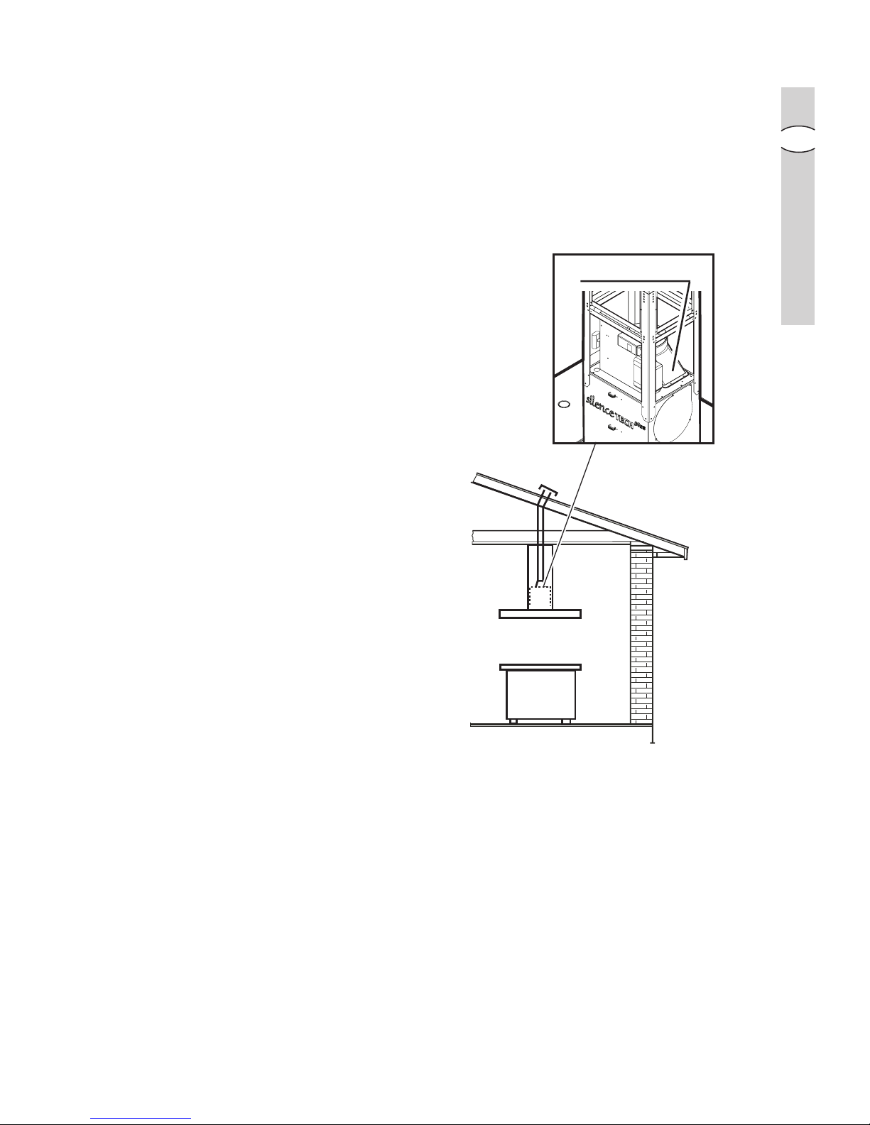
Extraction modeExtraction mode
Extraction modeExtraction mode
Extraction mode
• In this mode fumes are extracted to
the outside via a
hosehose
hosehose
hose connected to
the
coupling ringcoupling ring
coupling ringcoupling ring
coupling ring.
• In order to obtain the best performance the hose should have a diameter
equal to the outlet hole.
RecirRecir
RecirRecir
Recir
culation modeculation mode
culation modeculation mode
culation mode
• The air is filtered through a
charchar
charchar
char
coalcoal
coalcoal
coal
filterfilter
filterfilter
filter and returned to the kitchen.
• You will need an original charcoal filter
for the recirculation mode. (See
Special Accessories).
Coupling ringCoupling ring
Coupling ringCoupling ring
Coupling ring
Page 8

88
88
8
electr electr
electr electr
electr
oluxolux
oluxolux
olux control panel
GB
Control Panel
• Best results are obtained by using a
low speed for normal conditions and
a high speed when odours are more
concentrated.
Turn the hood on a few minutes
before you start cooking.
The hood should be left on after
cooking for about 15 minutes or until
all the odours have disappeared.
• The hood can also be commanded
from the control panel or the remote
control. (the remote control is a
special accessory and is ordered
separately).
•
CorrCorr
CorrCorr
Corr
ect ventilation:ect ventilation:
ect ventilation:ect ventilation:
ect ventilation: If the cooker
hood is to work correctly there must
be an under pressure in the kitchen.
It is important to keep the kitchen
windows closed and have a window
in an adjacent room open.
• The control switches are located on
the hood’s front panel
Page 9

electrolux electrolux
electrolux electrolux
electrolux control panel
99
99
9
GB
Model EFModel EF
Model EFModel EF
Model EF
A 9673A 9673
A 9673A 9673
A 9673
1.1.
1.1.
1.
Light switch, ON/OFF:Light switch, ON/OFF:
Light switch, ON/OFF:Light switch, ON/OFF:
Light switch, ON/OFF:press briefly to switch hob lighting on, press and hold
for more than 2 seconds to switch upper lighting on.
22
22
2.
Mains switch, ON/OFFMains switch, ON/OFF
Mains switch, ON/OFFMains switch, ON/OFF
Mains switch, ON/OFF
Press for less than 1 1/2 seconds and the cooker hood goes into the "
standstand
standstand
stand
byby
byby
by" position (dot
“a”“a”
“a”“a”
“a” on display is illuminated).
Press for more than 1 1/2 seconds and the cooker hood turns OFF, ALL the
controls (except the light push button) are disabled (the display is off).
Press again for more than 1 1/2 seconds to reset the cooker hood to "stand
by".
3.3.
3.3.
3.
Filters saturation rFilters saturation r
Filters saturation rFilters saturation r
Filters saturation r
eset key: eset key:
eset key: eset key:
eset key: see the relative text on the following pages.
44
44
4.
Start and choice of motor speed 1-2-3-1-2...Start and choice of motor speed 1-2-3-1-2...
Start and choice of motor speed 1-2-3-1-2...Start and choice of motor speed 1-2-3-1-2...
Start and choice of motor speed 1-2-3-1-2...
55
55
5.
Intensive speed ON/OFF: Intensive speed ON/OFF:
Intensive speed ON/OFF: Intensive speed ON/OFF:
Intensive speed ON/OFF: The Intensive speed runs for 5 minutes:
If the hood is on when the Intensive speed is activated, the hood will revert to
previous speed after 5 minutes. If the hood is off when the Intensive speed is
activated, the hood will automatically turn off after 5 minutes.
The letter
P P
P P
P appears on the display and the remaining time (the dot
“b”“b”
“b”“b”
“b” on
display is flashing), if interrupted an acoustic signal is heard.
66
66
6.
Self-TSelf-T
Self-TSelf-T
Self-T
imer ON/OFF: imer ON/OFF:
imer ON/OFF: imer ON/OFF:
imer ON/OFF: times all the speed levels (the dot
“a”“a”
“a”“a”
“a” on display is
flashing), and then the cooker hood switches off:
The self-timer is set as follows:
1st speed level 20 minutes
2nd speed level 15 minutes
3rd speed level 10 minutes
The display shows the remaining operation time, at the end of the time an
acoustic signal is heard. Depressing the push-button again exits the function.
77
77
7.
DisplayDisplay
DisplayDisplay
Display
Should the hood or the controls fail to operate: disconnect the power supply for at
least 5 seconds. After reconnecting the power supply wait 15 seconds and then
check that the cooker hood is now operating correctly.
ab
123 456
7
Page 10

1010
1010
10
electr electr
electr electr
electr
oluxolux
oluxolux
olux control panel
GB
GrGr
GrGr
Gr
ease and charease and char
ease and charease and char
ease and char
coal filtercoal filter
coal filtercoal filter
coal filter
maintenance indicatormaintenance indicator
maintenance indicatormaintenance indicator
maintenance indicator
This hood is fitted with a device that
indicates when it is necessary to clean
the grease filter or the charcoal filter (if
the hood is used in the recirculation
version with a charcoal filter).
On delivery, the hood is not supplied
with a charcoal filter, so the saturation
indicator will be disabled.
If the hood is to be used with a
charcoal filter, the saturation
indicator light must be enabled as
follows:
Set in "
OFFOFF
OFFOFF
OFF" the hood.
Press buttons
33
33
3 and
44
44
4 simultaneously
and hold them for 3 seconds. At first
only the grease filter LED
FF
FF
F will light up,
but when the charcoal filter LED
CC
CC
C
lights up the saturation indicator will be
enabled.
To disable it: Press buttons
33
33
3 and
44
44
4
again simultaneously and hold
them for 3 seconds, until the charcoal
filter LED goes out.
Grease filter LED (F)
LED
FF
FF
F will start to flash when it is time
to clean the grease filter.
Cleaning will be necessary after 40
working hours. Always comply with the
maintenance instructions for the grease
filter.
Charcoal filter LED (C)
The charcoal filter LED
CC
CC
C will start to
flash when the charcoal filter needs to
be replaced.
This operation is necessary after
approximately 160 working hours.
Resetting the saturation indicator
After cleaning or replacing the filters,
press button
33
33
3 for 3 seconds until the
grease filter LED
FF
FF
F or the charcoal filter
LED
CC
CC
C stops flashing.
Page 11
electrolux electrolux
electrolux electrolux
electrolux control panel
1111
1111
11
GB
Maintenance and Care
••
••
•
BeforBefor
BeforBefor
Befor
e performing any maintenance operation, isolate the hood fre performing any maintenance operation, isolate the hood fr
e performing any maintenance operation, isolate the hood fre performing any maintenance operation, isolate the hood fr
e performing any maintenance operation, isolate the hood fr
om theom the
om theom the
om the
electrical supply by switching ofelectrical supply by switching of
electrical supply by switching ofelectrical supply by switching of
electrical supply by switching of
f at the connector and rf at the connector and r
f at the connector and rf at the connector and r
f at the connector and r
emoving theemoving the
emoving theemoving the
emoving the
connector fuse.connector fuse.
connector fuse.connector fuse.
connector fuse.
Or if the appliance has been connected thrOr if the appliance has been connected thr
Or if the appliance has been connected thrOr if the appliance has been connected thr
Or if the appliance has been connected thr
ough a plug and socket, then theough a plug and socket, then the
ough a plug and socket, then theough a plug and socket, then the
ough a plug and socket, then the
plug must be rplug must be r
plug must be rplug must be r
plug must be r
emoved fremoved fr
emoved fremoved fr
emoved fr
om the socket.om the socket.
om the socket.om the socket.
om the socket.
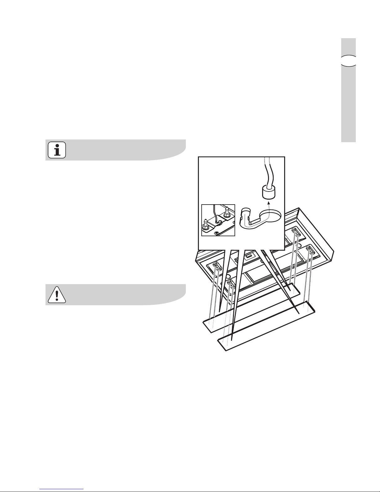
Air suction panelsAir suction panels
Air suction panelsAir suction panels
Air suction panels
Remove the perimeter air suction
panels to access the grease filters.
The perimeter air suction panels are
attached to the cooker hood by a
series of
pinspins
pinspins
pins and
coupling springscoupling springs
coupling springscoupling springs
coupling springs;
pull them outwards and detach them
from the
fastening cablefastening cable
fastening cablefastening cable
fastening cable.
Clean the perimeter air suction panels
as often as the grease filters (for more
information about gentle cleaning
methods, read the paragraph
“Cleaning” in the pages that follow).
When refitting the perimeter air suction
panels, ALWAYS reattach the fastening
cables.
Make sure the panels are attached to
the cooker hood properly (snapfastened).
x 4
Page 12
1212
1212
12
electr electr
electr electr
electr
oluxolux
oluxolux
olux maintenance and care
GB
Metal grMetal gr
Metal grMetal gr
Metal gr
ease filterease filter
ease filterease filter
ease filter
• The purpose of the grease filters is to
absorb grease particles which form
during cooking and it
mustmust
mustmust
must always be
used, either in the external extraction
or internal re-circulation function.
Attention: the metal grease filters
must be removed and washed, either
by hand or in the dishwasher, every
four weeks.
Removing the metal grRemoving the metal gr
Removing the metal grRemoving the metal gr
Removing the metal gr
ease filterease filter
ease filterease filter
ease filter
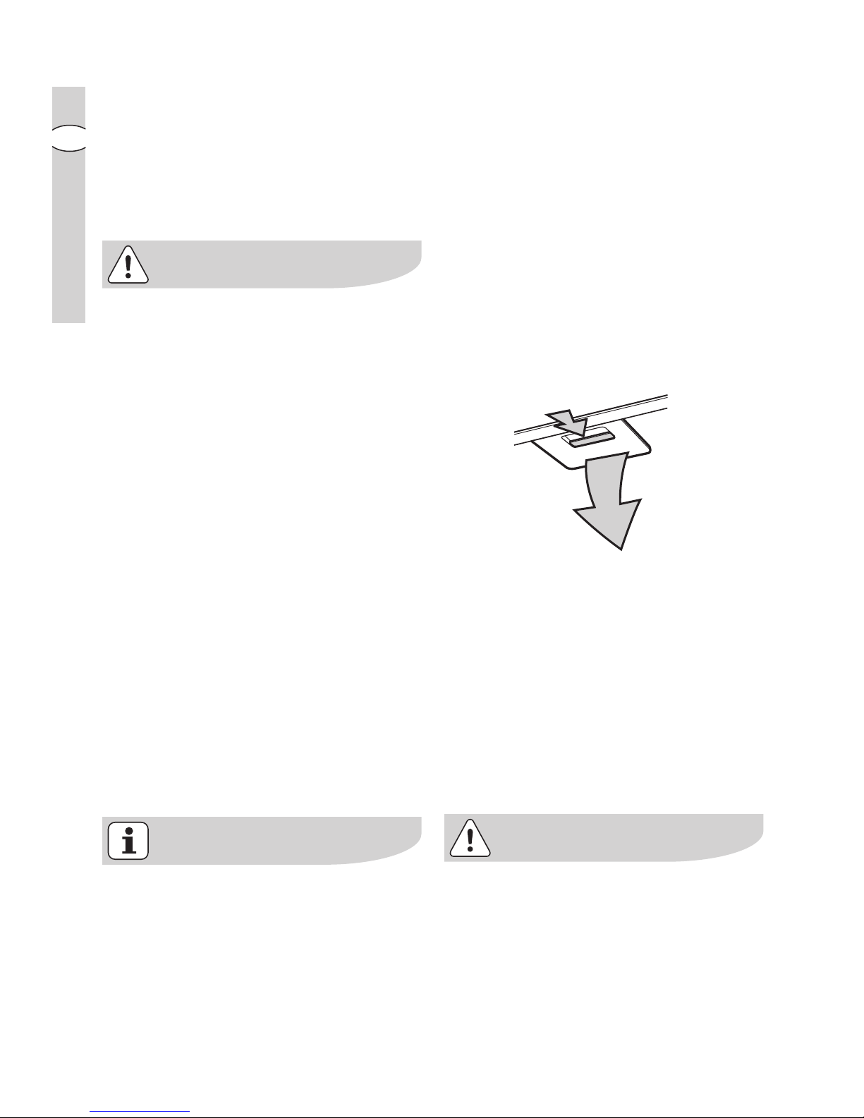
• Use the spring handle and remove
the filter downward.
Hand washingHand washing
Hand washingHand washing
Hand washing
Soak grease filters for about one hour
in hot water with a grease-loosening
cleaner, then rinse off thoroughly with
hot water. Repeat the process if
necessary. Refit the grease filters
when they are dry.
DishwasherDishwasher
DishwasherDishwasher
Dishwasher
Place grease filters in the dishwasher.
Select most powerful washing
programme and highest temperature,
at least 65°C. Repeat the process.
Refit the grease filters when they are
dry.
When washing the metal grease filter
in the dishwasher a slight
discolouration of the filter can occur,
this does not have any impact on its
performance.
• Clean the inner housing using a hand
hot solution only(never use caustic
detergents, abrasive powders or
brushes).
Page 13
electrolux electrolux
electrolux electrolux
electrolux maintenance and care
1313
1313
13
GB
CharChar
CharChar
Char
coal filtercoal filter
coal filtercoal filter
coal filter
• The charcoal filter should only be
used if you want to use the hood in
recirculation mode.
• To do this you will need an original
charcoal filter (available from your
local Service Force Centre).
•
Cleaning/rCleaning/r
Cleaning/rCleaning/r
Cleaning/r
eplacing the chareplacing the char
eplacing the chareplacing the char
eplacing the char
coal filtercoal filter
coal filtercoal filter
coal filter
Unlike other charcoal filters, the
LONGLIFE charcoal filter can be
cleaned and reactivated.
With normal use the filter should be
cleaned every second month (when
using the hood 2,5 hours per day,on
avarage). The best way to clean the
filter is in the dishwasher. Use normal
detergent and choose the highest
temperature (65º C). Wash the filter
separately so that no food parts gets
stuck on the filter and later causes bad
odours. To reactivate the charcoal, the
filter should be dried in an oven for 10
minutes with a maximum temperature
of 100º C.
After approximately three years of use,
the charcoal filter should be replaced
with a new, as the odour reduction
capacity will be reduced.
•
FittingFitting
FittingFitting
Fitting
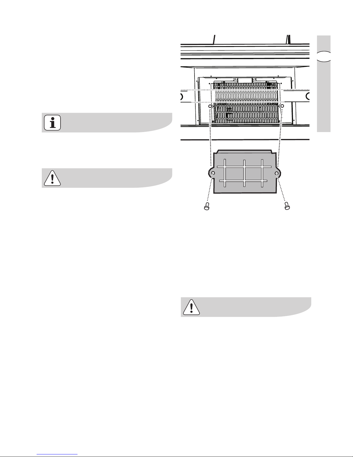
Position the carbon filter inside the
hood to cover the protection grill of
the motor.
Fix the filter with 2 lateral knobs.
•
TT
TT
T
o ro r
o ro r
o r
emoveemove
emoveemove
emove proceed in the reverse
order.
• Always specify the hood model code
number and serial number when
ordering replacement filters. This
information is shown on the rating
plate located on the inside of the unit.
• The charcoal filter can be ordered
from your local Service Force Centre.
Page 14
1414
1414
14
electr electr
electr electr
electr
oluxolux
oluxolux
olux maintenance and care
GB
WW
WW
W
arar
arar
ar
ningning
ningning
ning
• Failure to observe the instructions on
cleaning the unit and changing the
filters will cause a fire hazard. You are
therefore strongly recommended to
follow these instructions.
• The manufacturer declines all
responsibility for any damage to the
motor or any fire damage linked to
inappropriate maintenance or failure
to observe the above safety
recommendations.
Changing the light bulb(s)Changing the light bulb(s)
Changing the light bulb(s)Changing the light bulb(s)
Changing the light bulb(s)
•
Disconnect the cooker hood frDisconnect the cooker hood fr
Disconnect the cooker hood frDisconnect the cooker hood fr
Disconnect the cooker hood fr
omom
omom
om
the mains supplythe mains supply
the mains supplythe mains supply
the mains supply
..
..
.
••
••
•
Prior to touching the light bulbsPrior to touching the light bulbs
Prior to touching the light bulbsPrior to touching the light bulbs
Prior to touching the light bulbs
ensurensur
ensurensur
ensur
e they are they ar
e they are they ar
e they ar
e cooled down.e cooled down.
e cooled down.e cooled down.
e cooled down.
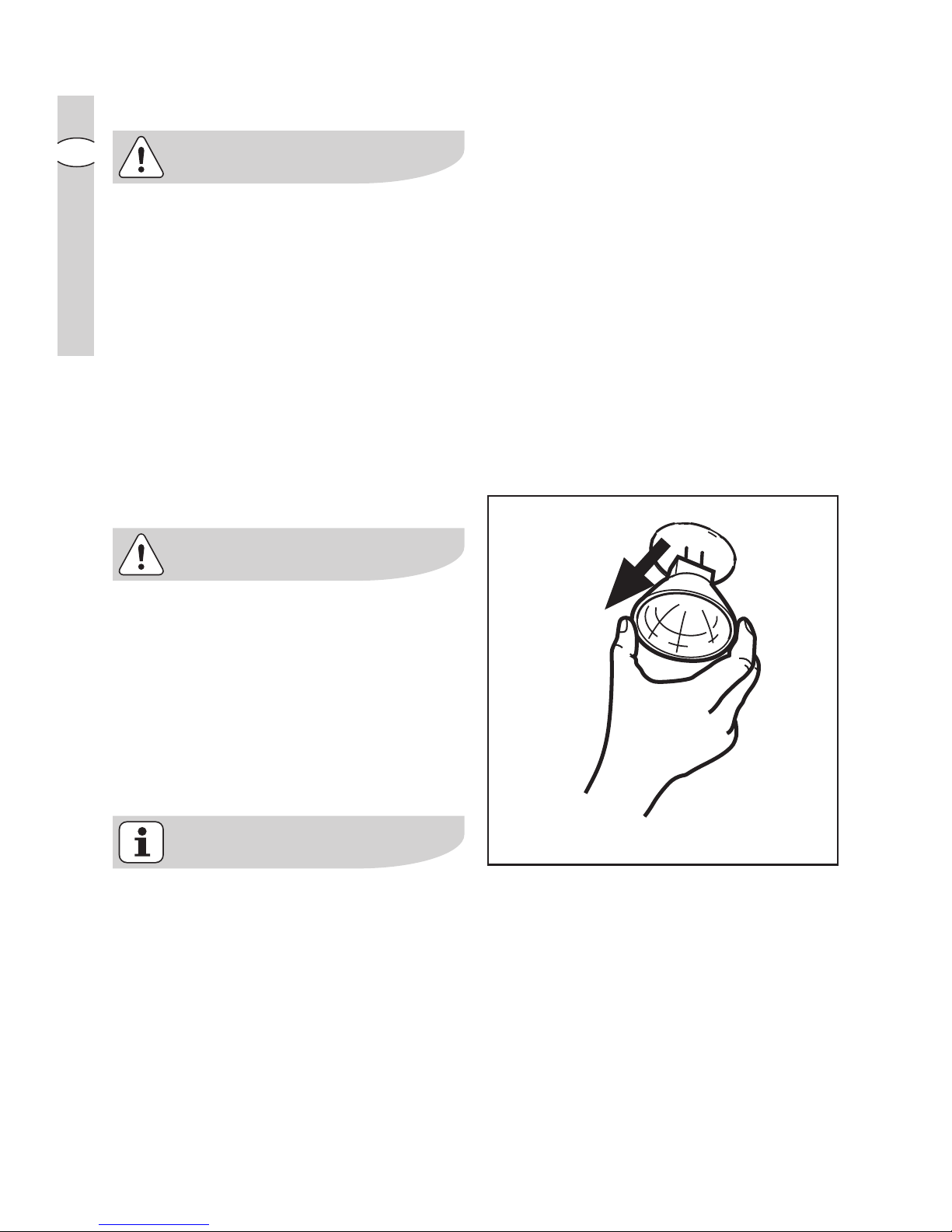
• Replace the old bulb with a new one
of the same type.
• If the light does not come on, make
sure the bulb has been inserted in
correctly before contacting your local
Service Force Centre.
20W max20W max
20W max20W max
20W max
GU4 - 12 V - Ø 35mm - 30° - Dichroic
Page 15

electrolux electrolux
electrolux electrolux
electrolux maintenance and care
1515
1515
15
GB
Cleaning the hoodCleaning the hood
Cleaning the hoodCleaning the hood
Cleaning the hood
• Clean the outside of the hood using a
damp cloth and a solution of water
and mild washing up liquid.
• Never use corrosive, abrasive or
flammable cleaning products or
products containing bleach.
• Never insert pointed objects in the
motor’s protective grid.
• Only ever clean the switch panel and
filter grill using a damp cloth and mild
washing up liquid.
• Clean all the plastic parts with a soft
cloth soaked in warm water and
neutral soap.
• It is extremely important to clean the
unit and change the filters at the
recommended intervals. Failure to do
so will cause grease deposits to build
up that could constitute a fire hazard.
Page 16

1616
1616
16
electr electr
electr electr
electr
oluxolux
oluxolux
olux special accessories
GB
Special accessoriesSpecial accessories
Special accessoriesSpecial accessories
Special accessories
CharChar
CharChar
Char
coal filtercoal filter
coal filtercoal filter
coal filter Type 967
Remote contrRemote contr
Remote contrRemote contr
Remote contr
olol
olol
ol RM 6940
Something Not Working
If your appliance fails to work properly please carry out the following checks.
SymptomSymptom
SymptomSymptom
Symptom
The cooker hood will not start...
The cooker hood is not working
The cooker hood has switched off
during operation...
SolutionSolution
SolutionSolution
Solution
Check that: Check that:
Check that: Check that:
Check that: The hood is connected
to the electricity supply.
Check that a fan speed has been
selected.
Check that: Check that:
Check that: Check that:
Check that: The fan speed is set high
enough for the task.
The grease filters are clean.
The kitchen is adequately vented to
allow the entry of fresh air.
If set up for recirculation, check that
the charcoal filter is still effective.
If set up for extraction, check that the
ducting and outlets are not blocked.
The safety cut-out device has been
tripped. Turn off the hob and then wait
for the device to reset. If the hood has
been installed below the heights
indicated in the installation instructions
the motor will cut-out frequently which
will damage the hood.
If after all these checks, the problem persists, contact your local Service Centre,
quoting the model and serial number.
Please note that it will be necessary to provide proof of purchase for any inguarantee service calls.
In-guarantee customers should ensure that the above checks have been made as
the engineer will make a charge if the fault is not a mechanical or electrical
breakdown.
Page 17

electrolux electrolux
electrolux electrolux
electrolux installation
1717
1717
17
GB
Installation
TT
TT
T
echnical Detailsechnical Details
echnical Detailsechnical Details
echnical Details
EFEF
EFEF
EF
A 9673 (EFA 9673 (EF
A 9673 (EFA 9673 (EF
A 9673 (EF
A 90673)A 90673)
A 90673)A 90673)
A 90673)
Dimensions (in cm):Dimensions (in cm):
Dimensions (in cm):Dimensions (in cm):
Dimensions (in cm):
Height (Extraction mode): 89,5 ÷ 118,5
Height (Recirculation mode): 89,5 ÷ 129,5
Width: 99,8
Depth: 70
Maximum absorbed power:Maximum absorbed power:
Maximum absorbed power:Maximum absorbed power:
Maximum absorbed power:
350 W350 W
350 W350 W
350 W
Motor: 250 W
Lighting: 5 x 20 W
Length of the cable:Length of the cable:
Length of the cable:Length of the cable:
Length of the cable:
150 cm150 cm
150 cm150 cm
150 cm
Electrical connection:Electrical connection:
Electrical connection:Electrical connection:
Electrical connection:
220-240 V220-240 V
220-240 V220-240 V
220-240 V
Fuse rating:Fuse rating:
Fuse rating:Fuse rating:
Fuse rating:
5A T5A T
5A T5A T
5A T
Mounting accessories includedMounting accessories included
Mounting accessories includedMounting accessories included
Mounting accessories included
1 Allan wrench for torx screws
12 nuts
6 screws 6 x 70 mm
6 dowels Ø 10 mm
12 screws 4 x 7 mm
58 screws 3.5 x 9.5
1 deflector (with extensions)
Page 18
1818
1818
18
electr electr
electr electr
electr
oluxolux
oluxolux
olux installation
GB
Electrical connection
(not for UK)
Safety warSafety war
Safety warSafety war
Safety war
nings for the electriciannings for the electrician
nings for the electriciannings for the electrician
nings for the electrician
Before connecting the appliance to the
power supply, check that the voltage
indicated on the rating plate
corresponds to the mains power supply
available. Appliances fitted with a plug
can be connected to any standard
power socket within easy access.
Should it be necessary to provide a
fixed connection, the hood must only
be installed by an electrician authorised
by the local electricity board. When
installing, an omnipolar disconnector
with a distance of at least 3 mm
between contacts must be provided.
Fixed connection of the appliance must
only be carried out by an authorised
electrician.
Electrical connection for
UK only
Safety warSafety war
Safety warSafety war
Safety war
nings for the electriciannings for the electrician
nings for the electriciannings for the electrician
nings for the electrician
Connect the hood to the mains supply
via a double pole switch which has 3
mm minimum separation between the
contacts.
The switch must be accessible at all
times.
The following is valid in the United
Kingdom only:
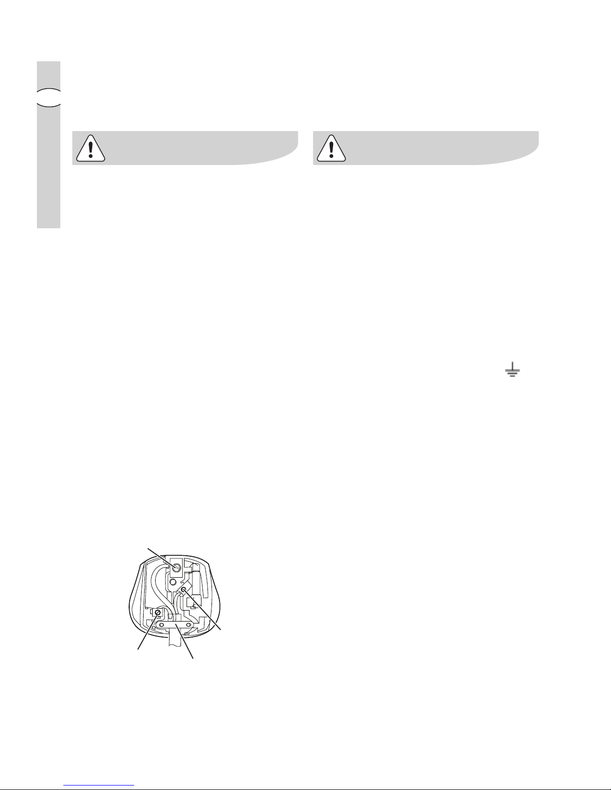
- the wire which is coloured green and
yellow must be connected to the
terminal which is marked with the
letter E or by the earth symbol ( ),
or coloured green or green and
yellow;
- the wire which is coloured blue must
be connected to the terminal which is
marked with the letter N or coloured
black, -
- the wire which is coloured brown
must be connected to the terminal
which is marked with the letter L or
coloured red.
BROWN
CORD CLAMP
BLUE
GREEN & YELLOW
5AT
Page 19
electrolux electrolux
electrolux electrolux
electrolux installation
1919
1919
19
GB
InstallationInstallation
InstallationInstallation
Installation
Make surMake sur
Make surMake sur
Make sur
e that the cooker hood is disconnected fre that the cooker hood is disconnected fr
e that the cooker hood is disconnected fre that the cooker hood is disconnected fr
e that the cooker hood is disconnected fr
om the power supply beforom the power supply befor
om the power supply beforom the power supply befor
om the power supply befor
ee
ee
e
carrying out the installation.carrying out the installation.
carrying out the installation.carrying out the installation.
carrying out the installation.
The cooker hood comes with fixing plugs which are suitable for use with most
walls/ceilings. Nevertheless, you should ask a qualified technician to assess the
suitability of the materials in accordance with the type of wall/ceiling. The wall/
ceiling must be sufficiently sturdy so as to support the weight of the cooker hood.
Remove the perimeter air suction panels and the grease filters.
Before installing the product:
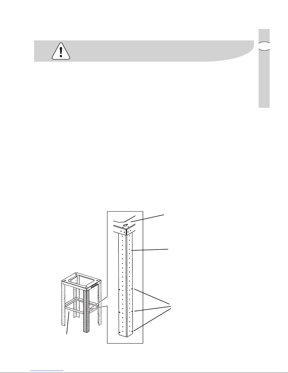
The perforated frame for the cooker hood is supplied prior to installation in parts.
The main parts making up the perforated frame are as follows:
• the upper perforated frame
AA
AA
A (x1)
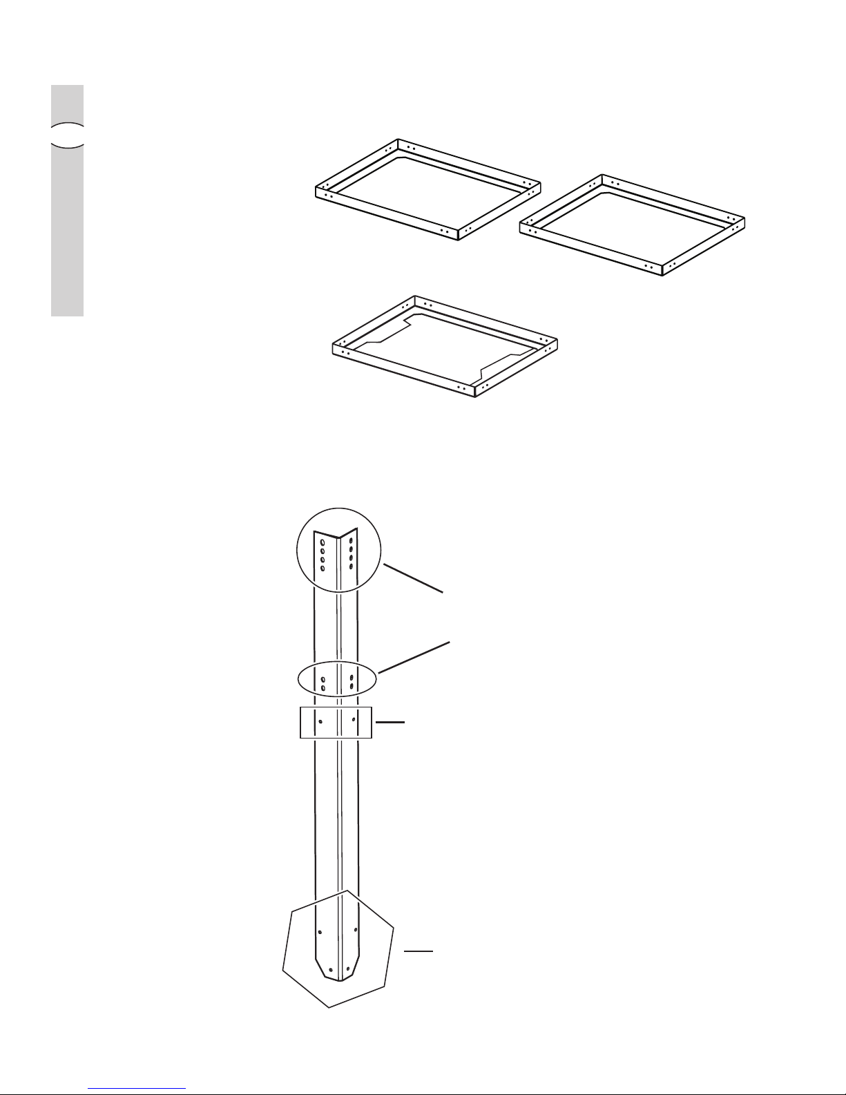
• the perforated frame extension brackets
BB
BB
B (x4)
• the reinforcement brackets
CC
CC
C (x3), of which:
2 are for use on the upper part
C1 - C1 -
C1 - C1 -
C1 - 1 of which is pre-assembled
1 is for use on the lower part
C2C2
C2C2
C2
Description of the upper perforated frame A:Description of the upper perforated frame A:
Description of the upper perforated frame A:Description of the upper perforated frame A:
Description of the upper perforated frame A:
Point at which the perforated
frame is fixed/hooked to the
ceiling
Fixing points for extension
brackets
BB
BB
B
Fixing points for the 2
reinforcement brackets
C1C1
C1C1
C1
Reinforcement brackets
C1C1
C1C1
C1
Page 20
2020
2020
20
electr electr
electr electr
electr
oluxolux
oluxolux
olux installation
GB
Description of the rDescription of the r
Description of the rDescription of the r
Description of the r
einforeinfor
einforeinfor
einfor
cement brackets C1 and C2cement brackets C1 and C2
cement brackets C1 and C2cement brackets C1 and C2
cement brackets C1 and C2
reinforcement brackets
C1C1
C1C1
C1
(upper and intermediate)
reinforcement bracket
C2C2
C2C2
C2 (lower)
Points at which they
are fixed to the upper
frame
Fixing points for
the lower
reinforcement
bracket
C2C2
C2C2
C2
Points at which
the bracket is fixed
to the cooker
hood
Description of the extension brackets B:Description of the extension brackets B:
Description of the extension brackets B:Description of the extension brackets B:
Description of the extension brackets B:
Page 21
electrolux electrolux
electrolux electrolux
electrolux installation
2121
2121
21
GB
PrPr
PrPr
Pr
eparing the structural supporteparing the structural support
eparing the structural supporteparing the structural support
eparing the structural support
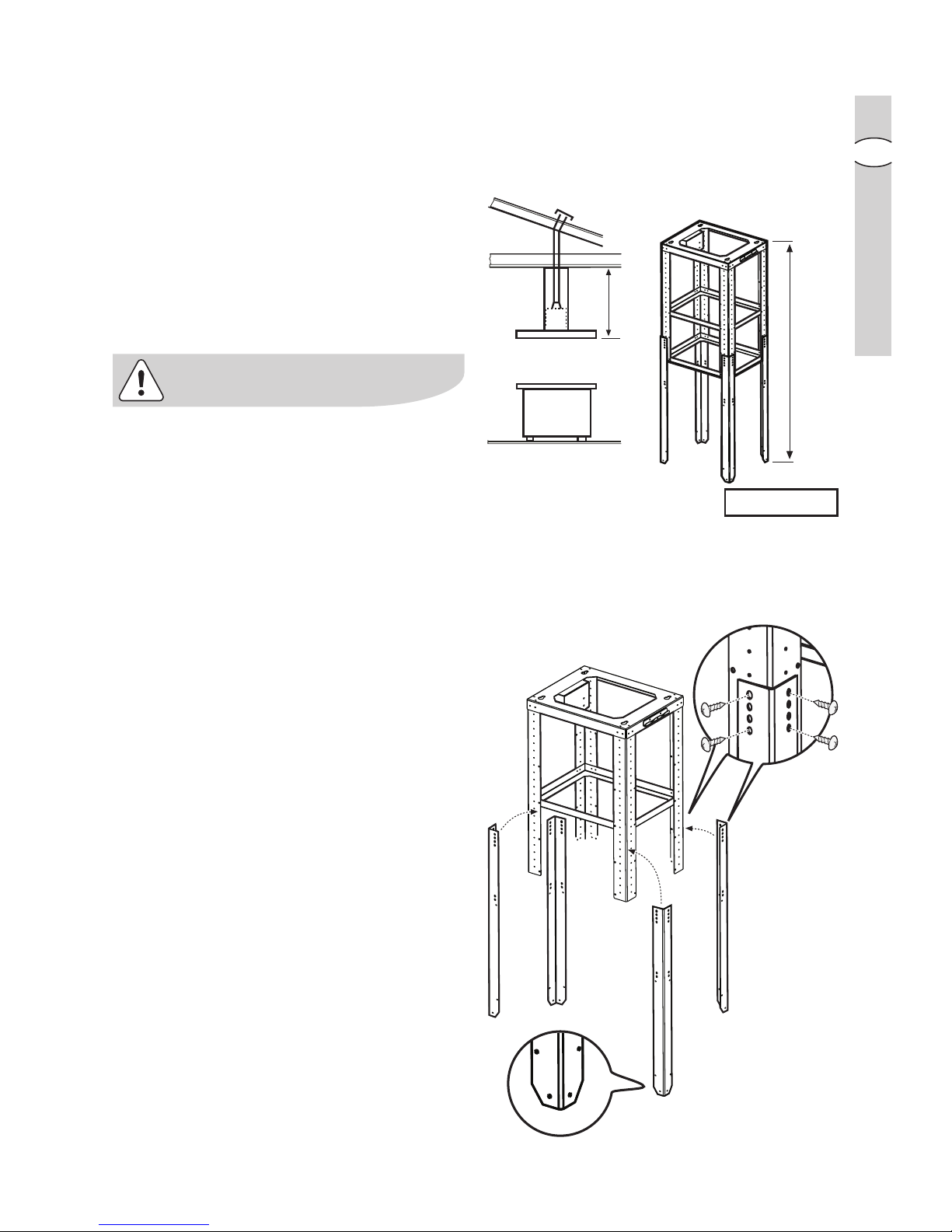
Before assembling the perforated
frame, calculate the extension it
requires.
Use the formula given in the adjacent
diagram to help you.
Make a note of measurement
EE
EE
E in this
booklet; it will serve as a reference
when you are calculating the length of
the exhaust tube.
Measurement
LL
LL
L should respect the
minimum permitted distances from the
hob, as indicated in the paragraph
entitled “Safety warnings – for the
installer”.
• Fit the extension brackets
BB
BB
B to the
perforated frame using 4 screws for
each, so that the perforated frame
can be extended to the calculated
length
EE
EE
E.
L
E
E (mm)= L- 355
Page 22
2222
2222
22
electr electr
electr electr
electr
oluxolux
oluxolux
olux installation
GB
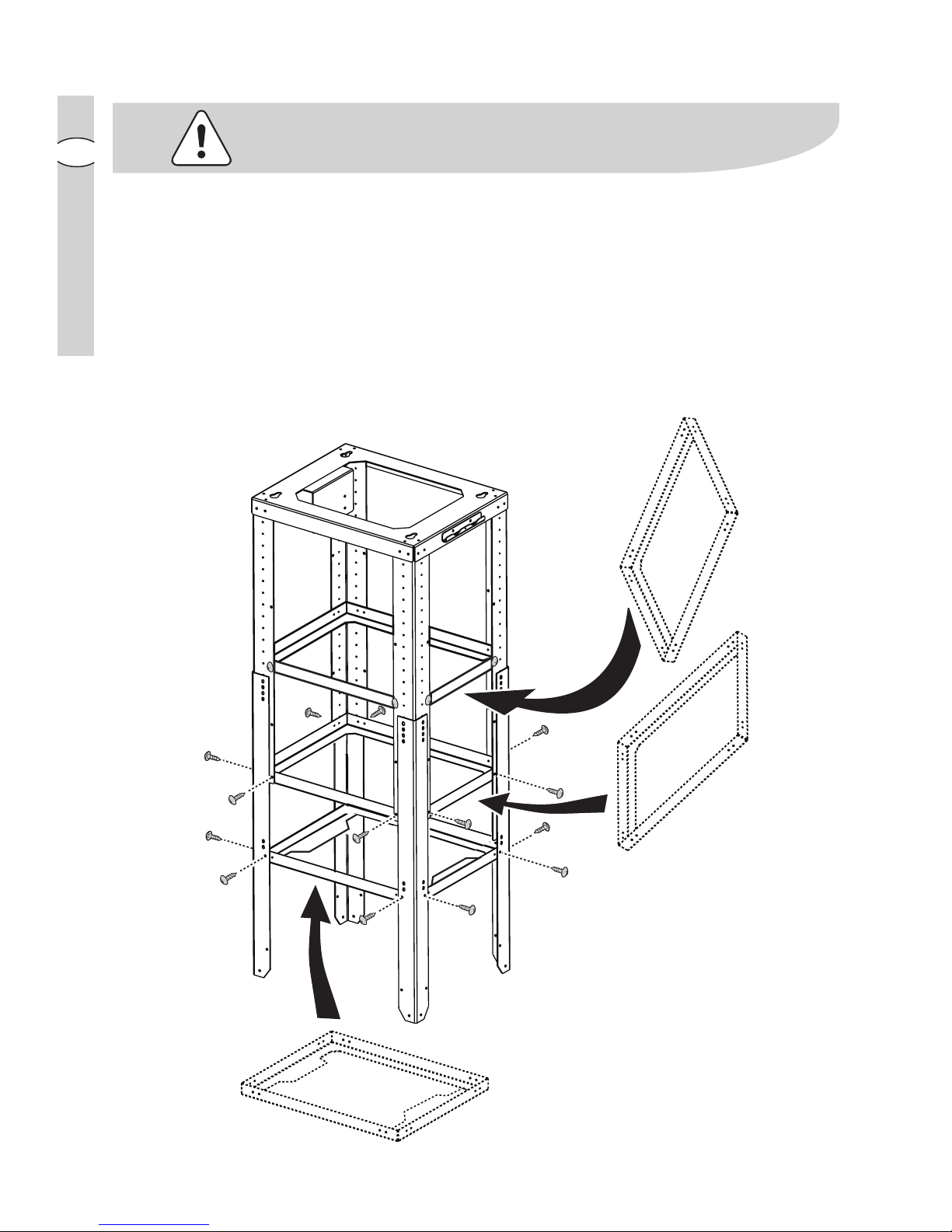
For perforated frame extensions (please refer to measurement
EE
EE
E calculated
previously):
-
smaller than 690 mm: smaller than 690 mm:
smaller than 690 mm: smaller than 690 mm:
smaller than 690 mm: this extension requires only one bracket (
C1C1
C1C1
C1); generally
this is already fixed in place.
-
between 690 mm and 795 mm: between 690 mm and 795 mm:
between 690 mm and 795 mm: between 690 mm and 795 mm:
between 690 mm and 795 mm: fit both
C1C1
C1C1
C1 brackets.
- greater than 800 mm: fit all available reinforcement brackets (
2 x C1 + 1 x C22 x C1 + 1 x C2
2 x C1 + 1 x C22 x C1 + 1 x C2
2 x C1 + 1 x C2)
Use 8 screws to fix each reinforcement bracket in place.
Note:Note:
Note:Note:
Note: One of the two
C1 C1
C1 C1
C1 brackets is usually already fitted when the appliance is
supplied.
C1
C1
C2
Page 23
electrolux electrolux
electrolux electrolux
electrolux installation
2323
2323
23
GB
•
For the rFor the r
For the rFor the r
For the r
ecirecir
ecirecir
ecir
culation mode only:culation mode only:
culation mode only:culation mode only:
culation mode only:
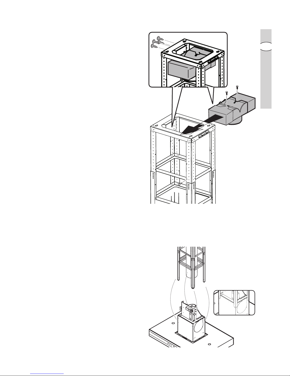
assemble the three parts of the
deflector (central part + 2 extensions)
using 2 screws so that once
assembled, the deflector is the same
width as the structural support.
Fasten the deflector inside the
structural support using 4 screws.
Fit an exhaust tube to the deflector
connection ring. The tube must be
300 mm shorter in length than the
structural support (please refer to
measurement
EE
EE
E calculated
previously).
Installing the structural support toInstalling the structural support to
Installing the structural support toInstalling the structural support to
Installing the structural support to
the cooker hoodthe cooker hood
the cooker hoodthe cooker hood
the cooker hood
• Fix the cooker hood to the structural
support using 16 screws (4 per
bracket).
F
Page 24
2424
2424
24
electr electr
electr electr
electr
oluxolux
oluxolux
olux installation
GB
Installing the structural support toInstalling the structural support to
Installing the structural support toInstalling the structural support to
Installing the structural support to
the ceilingthe ceiling
the ceilingthe ceiling
the ceiling
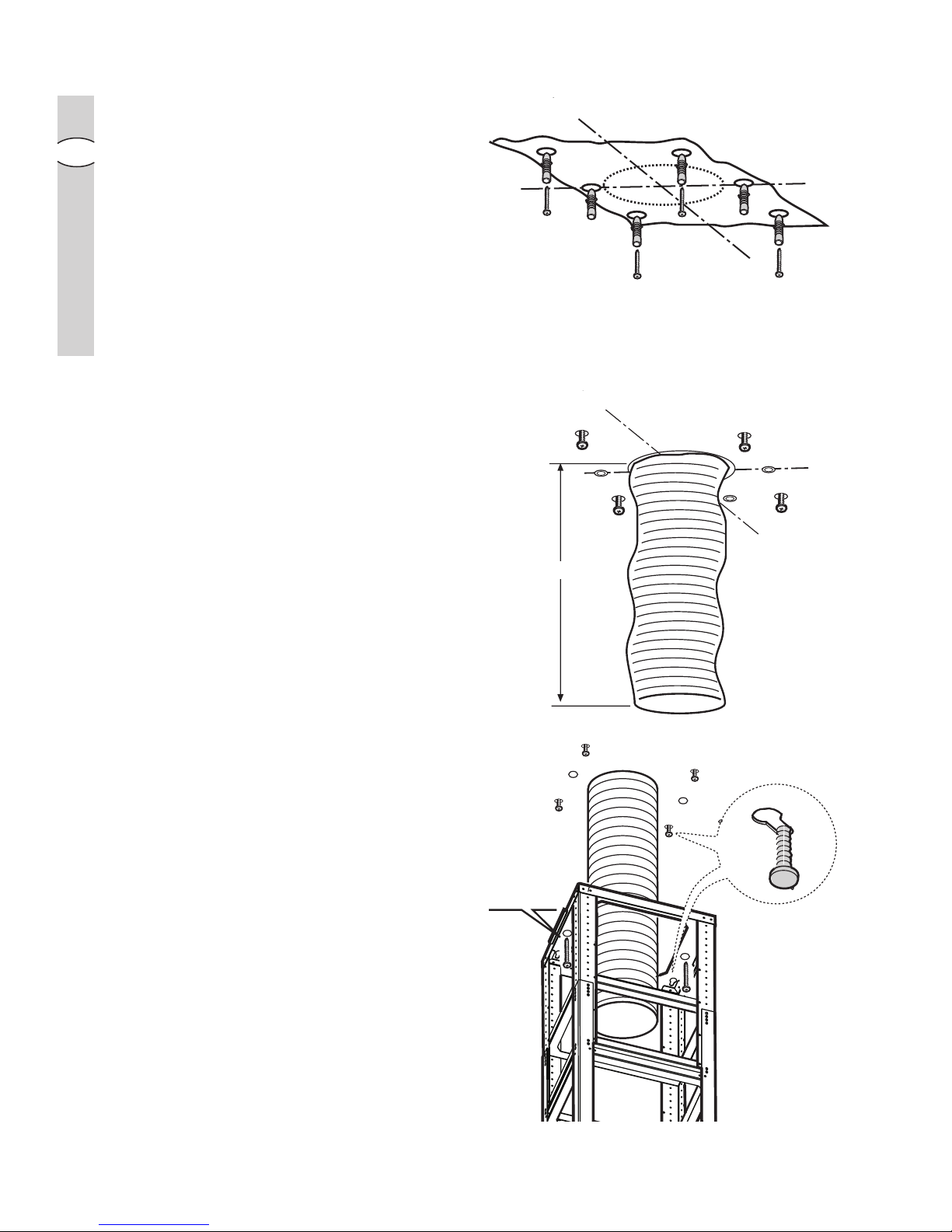
• Place the template on the ceiling
directly above the hob (the centre
and sides of the template should be
aligned with the centre and sides of
the hob).
Note: Note:
Note: Note:
Note: The side displaying the text
“FRONT” corresponds to the side
which will house the control panel
once installation is complete.
• Make the holes as indicated on the
template (6 holes for 6 screw
anchors) and partially tighten 4
screws into the screw anchors in the
corners (leave approximately 1 cm
between the head of the screw and
the ceiling).
• Prepare the electrical connection.
•
Ducted version only:Ducted version only:
Ducted version only:Ducted version only:
Ducted version only: Install an
exhaust tube long enough to reach
the outlet ring located above the
cooker hood.
The tube should be fitted to the
ceiling as an exhaust system to expel
fumes outside; the visible part should
be 180 mm shorter than the
structural support (please refer to
measurement
EE
EE
E calculated
previously).
• Install the structure to the ceiling,
onto the 4 pre-tightened screws and
then screw them in firmly.
• Fix it in place using 2 screws.
• Connect the exhaust tube to the
connection ring above the cooker
hood.
• Carry out the necessary electrical
connection.
X 4!
2 x
Ø6 x 70
FRONT
6 x Ø 10 + 4 x Ø 6x70
SX
DX
FRONT
E (mm)-180
Page 25
electrolux electrolux
electrolux electrolux
electrolux installation
2525
2525
25
GB
Installing the fluesInstalling the flues
Installing the fluesInstalling the flues
Installing the flues
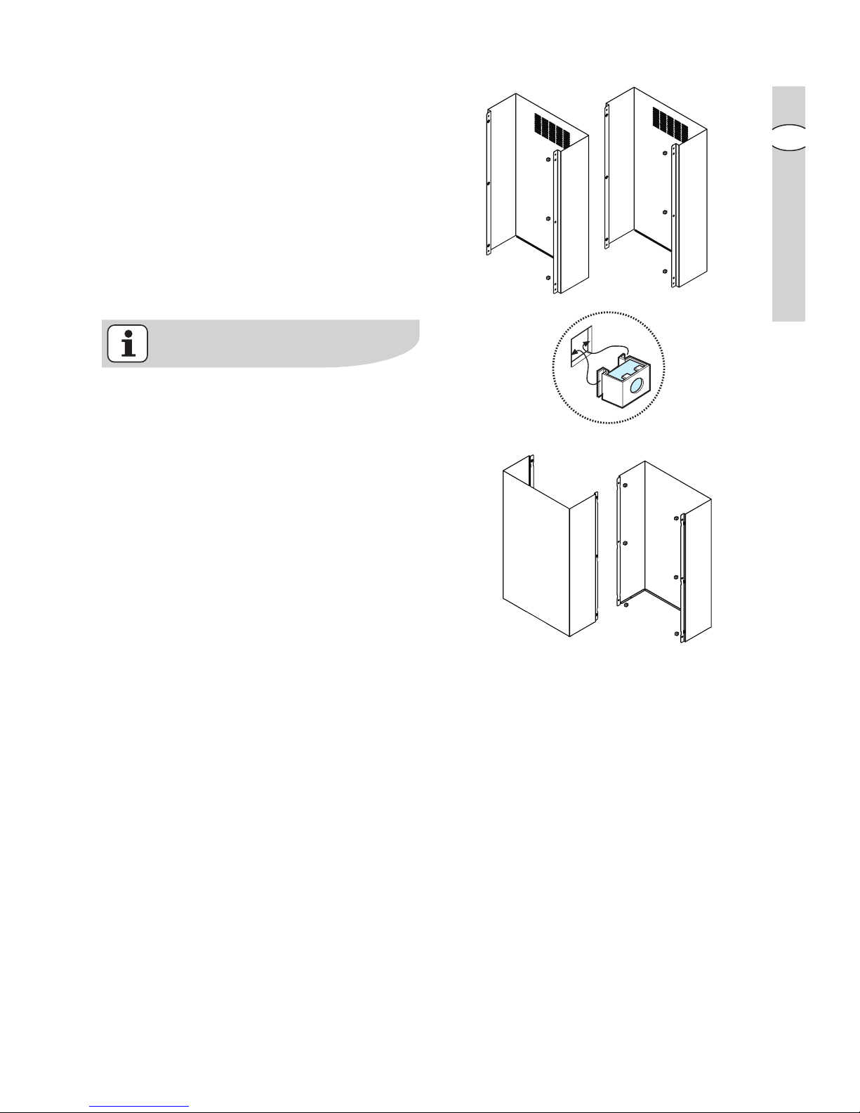
• Fix the nuts in place with the
couplings both on the upper internal
sections of the flues (P+Q) and on the
lower back section of the flues (R).
• Fix the two upper flue sections (P+Q)
directly onto the structural support of
the cooker hood according to the
assembly diagram (see adjacent
figure).
For the filter version, the upper
sections must be fitted so that the air
recirculation slots are facing upwards.
If you wish to use the cooker hood as
a ducted model, for aesthetic
purposes, the upper flue sections can
be turned upside down to hide the
slots when the lower flue sections are
installed.
P x 3
R x 6
Q x 3
P
Q
R
S
S x 0
Page 26
2626
2626
26
electr electr
electr electr
electr
oluxolux
oluxolux
olux installation
GB
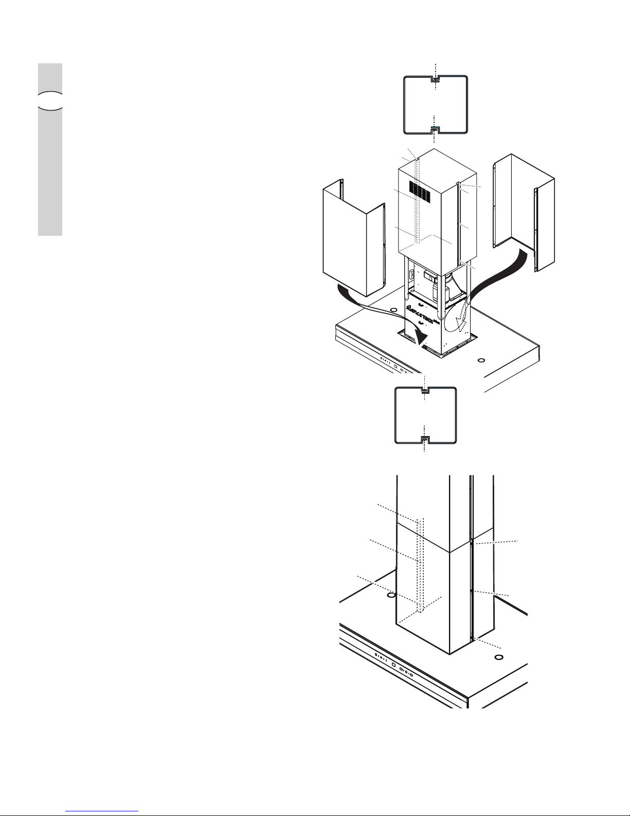
Fix the section in place using 6
screws (3 per side).
• Lift the flues and fix them onto the
structural support using 2 screws (1
per side).
• Install the lower back section of the
flue (R) by resting it on top of the
cooker hood in the correct position
(widen it slightly to allow for an easy
fit onto the upper flue).
• Install the lower front section of the
flue (S) and widen it slightly to allow
for an easy fit onto the upper section.
Fix the section in place using 6
screws (3 per side).
P
Q
R
S
P
Q
R
S
Page 27
electrolux electrolux
electrolux electrolux
electrolux installation
2727
2727
27
GB
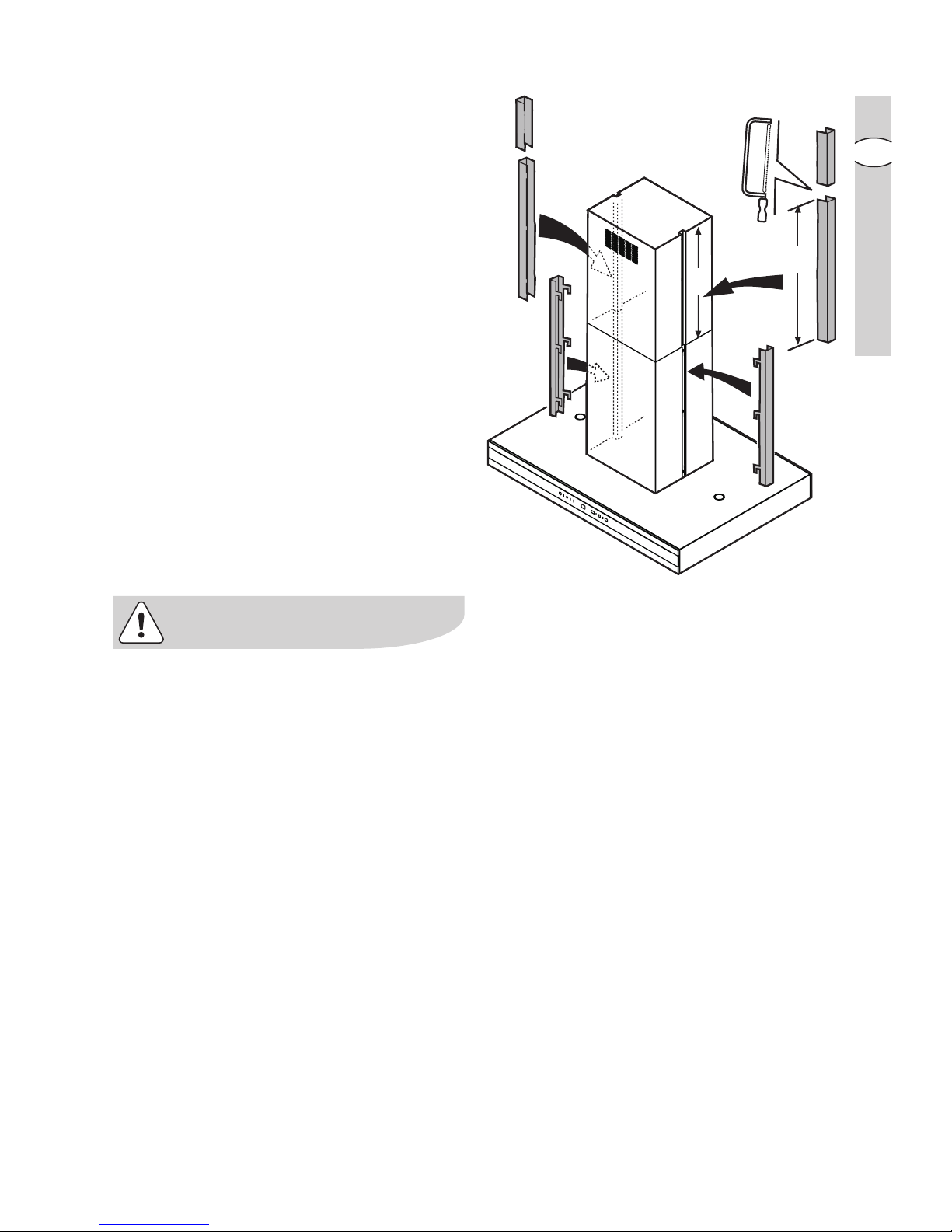
• Cover the fixing points with 4
casings:
The two lower parts may be hooked
on, however the upper parts must be
cut to size and snapped into place.
• Fix the lower flues in place from inside
the cooker hood using 2 screws.
Reattach the grease filters and the
perimeter air suction panels.
Connect the hood to the mains
electricity (wait about 15 seconds, the
time needed to calibrate the electronic
device that controls the functioning of
the hood), and check, finally, that it is
functioning well.
Only for EFOnly for EF
Only for EFOnly for EF
Only for EF
A 90673:A 90673:
A 90673:A 90673:
A 90673:
Attention! Le dispositif signalant laAttention! Le dispositif signalant la
Attention! Le dispositif signalant laAttention! Le dispositif signalant la
Attention! Le dispositif signalant la
saturation du filtrsaturation du filtr
saturation du filtrsaturation du filtr
saturation du filtr
e à charbon actif este à charbon actif est
e à charbon actif este à charbon actif est
e à charbon actif est
désactivé.désactivé.
désactivé.désactivé.
désactivé.
Pour activer le dispositif voir à la pagePour activer le dispositif voir à la page
Pour activer le dispositif voir à la pagePour activer le dispositif voir à la page
Pour activer le dispositif voir à la page
12.12.
12.12.
12.
X
X
 Loading...