

iNSTALLATiON AND SERVICEMUST BEPERFORMED BY A QUALiFiED iNSTALLER.
iMPORTANT: SAVE FOR LOCAL ELECTRICAL iNSPECTOR'S USE.
READ AND SAVE THESE iNSTRUCTiONS FOR FUTURE REFERENCE.
OBSERVE ALL GOVERNING CODES AND ORDINANCES.
If the information in this manual is not followed exactly, a fire
or explosion may result causing property damage, personal injury or death.
FOR YOUR SAFETY:
-- Do not store or use gasoline or other flammable vapors and liquids in
the vicinity of this or any other appliance.
-- WHAT TO DO IF YOU SMELL GAS:
, Do not try to light any appliance.
, Do not touch any electrical switch; do not use any phone in your
building.
, Immediately call your gas supplier from a neighbor's phone. Follow the
gas supplier's instructions.
, If you cannot reach your gas supplier, call the fire department.
-- Installation and service must be performed by a qualified installer,
service agency or the gas supplier.
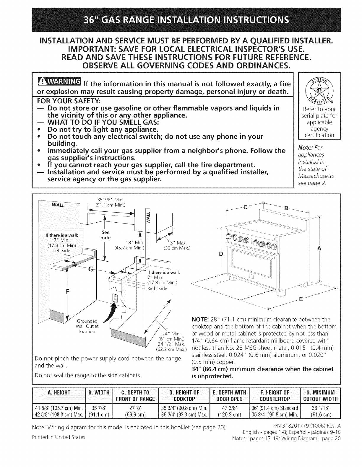
35 7/8" Min.
(91.1 cm Min.)
Refer to your
serial plate for
applicable
agency
certification
Note: For
appliances
instafled in
the state of
Massachusetts
seepage 2,
If there isawall:
7" Min.
(17.8 cm Min)
Left side
See
note
18" Min.
(45.7 cm Min.)
13" Max.
(33 cm Max.)
If there is a wall:
7" Min.
17.8 cm Min.)
Right side
_E j
NOTE: 28" (71.1 cm) minimum clearance between the
Grounded y .'"
Wall Outlet
location 24" Min.
(61 cm Min.)
24 1/2" Max.
(62.2 cm Max.)
Do not pinch the power supply cord between the range
and the wall.
Do not sealthe range to the side cabinets.
cooktop and the bottom of the cabinet when the bottom
of wood or metal cabinet is protected by not lessthan
1/4" (0.64 cm) flame retardant millboard covered with
not lessthan No. 28 MSG sheet metal, 0.01 5" (0.4 mm)
stainless steel, 0.024" (0.6 mm) aluminum, or 0.020"
(0.5 mm) copper.
34" (86.4 cm) minimum clearance when the cabinet
is unprotected.
A: HHEIGHT, B:WIDTII C:DEPTHTO D:HEIGHTOF E DEPTH.lWITH' F.HEIGHTOF G.MINIMUM
' FRONTOFRANGE COOKTOP DOOR OPEN COUNTERTOP CUTOUTWIDTH
415/8"(105.7cm)Min. 357/8" 27W' 353/4"(90.8cm) Min, 473/8" 36"(91.4cm)Standard 361/16"
425/8"(108.3cm)Max. (91,1cm) (69,9cm) 363/4"(93.3cm)Max. (120,3cm) 353/4"(90.8cm)Min. (91,6cm)
Note: Wiring diagram for this model is enclosed in this booklet (see page 20). P/N318201779 (1006) Rev.A
Printed in United States Notes - pages 17-19; Wiring Diagram - page 20
English - pages 1-8; EspaSol - p_iginas 9-16
iMPORTANT SAFETY
iNSTRUCTiONS
Installation of this range must conform with local codes
or, in the absence of local codes, with the National Fuel
Gas Code ANSI Z223.1/NFPA No.54.
When installing in a manufactured (mobile) home,
installation must conform with Manufactured Home
Construction and Safety Standard, title 24CFR, part
3280 [Formerly the Federal Standard for Mobile Home
Construction and Safety, title 24, HUD (part 280)] or,
when such standard is not applicable, the Standard for
Manufactured Home Installation, ANSI Z225.1/NFPA
501A-latest edition, or with CAN/CSA-Z240 MH, or with
local codes.
This range has been design certified by CSA
international. As with any appliance using gas and
generating heat, there are certain safety precautions you
should follow. You will find them in the Use and Care
Guide, read it carefully.
• Be sure your range is installed and grounded
properly by a qualified installer or service
technician.
• This range must be electrically grounded in
accordance with local codes or, in their absence,
with the National Electrical Code ANSI/NFPA No.
70--latest edition in the United States or with
CSA standard C22.1, Canadian Electrical Code,
Part I in Canada.
Make sure the wall coverings around the range
can withstand the heat generated by the range.
Before installing the range in an area covered
with linoleum or any other synthetic floor
covering, make sure the floor covering can
withstand heat at least 90°F/32°C above room
temperature without shrinking, warping or
discoloring. Do not install the range over carpeting
unless you place an insulating pad or sheet of 1/4"
(6.4 mm) thick plywood between the range and
carpeting.
Do not obstruct the flow of combustion air at the
oven vent nor around the base or beneath the
lower front panel of the range. Avoid touching the
vent openings or nearby surfaces as they may become
hot while the oven is in operation. This range requires
fresh air for proper burner combustion.
Never leave children alone or
unattended in the area where an appliance is in
use. As children grow, teach them the proper, safe use
of all appliances. Never leave the oven door open when
the range is unattended.
Stepping, leaning or sitting on the
door of this range can result in serious injuries and
can also cause damage to the range.
Do not store items of interest to children in
the cabinets above the range. Children could be
seriously burned climbing on the range to reach items.
To eliminate the need to reach over the surface
units, cabinet storage space above the units
should be avoided.
Adjust surface burner flame size so it does not
extend beyond the edge of the cooking utensil.
Excessiveflame is hazardous.
Do not use the oven as a storage space. This
creates a potentially hazardous situation.
Never use your range for warming or heating the
room. Prolonged use of the range without adequate
ventilation can be dangerous.
Do not store or use gasoline or other flammable
vapors and liquids near this or any other
appliance. Explosions or fires could result.
In the event of an electrical power outage, the surface
burners can be lit manually. To light a surface burner,
hold a lit match to the burner head and rapidly turn
the Surface Control knob to Med. Use caution when
lighting surface burners manually.
Remove broiler pan, food and other utensils
before self-cleaning the oven. Wipe up excess
spillage. Follow the cleaning instructions in the Use &
Care Guide.
Unlike the standard gas range, THIS COOKTOP
IS NOT REMOVABLE. Do not attempt to remove the
cooktop.
Special/nstructions for appliances installed in the State
of Massachusetts: This appliance can only be installed
in the State of Massachusetts by a Massachusetts
licensed plumber or gas fitter. When using a flexible
gas connector, it must not exceed 3 feet (36 inches) in
length. A "T" handle type manual gas valve must be
installed in the gas supply line to this appliance.
Never cover any slots, holes or pas-
sages in the oven bottom or cover an entire rack with
materials such asaluminum foil. Doing so blocks air
flow through the oven and may cause carbon monoxide
poisoning. Aluminum foil linings may also trap heat,
causing afire hazard.
All ranges can tip.
Injury to persons could result.
Install anti-tip device packed with range.
To reduce the risk of tipping of the range,
the range must be secured by properly in-
stalled anti-tip bracket(s) provided with the
range. Tocheck if the bracket is installed
properly, grasp the top rear edge of the
range and carefully tilt it forward to make
sure the range is anchored.
Important Notes to the Installer
1. Read all instructions contained in these installation
instructions before installing range.
2. Remove all packing material from the oven
compartments before connecting the electrical supply
to the range.
3. Observe all governing codes and ordinances.
4. Besure to leave these instructions with the consumer.
5. Note: For operation at 2000 ft. elevations above see
level, appliance rating shall be reduced by 4 percent
for each additional 1000 ft.
Important Note to the Consumer
Keepthese instructionswith your owner's guide for future
reference.
Optional Items Available:
• A Stainless Steel Kick Plate
A Black Knob Kit
Those kits can be ordered for purchase through an
Electrolux Service Center at 1-877-4ELECTROLUX(1-877-
435-3287).
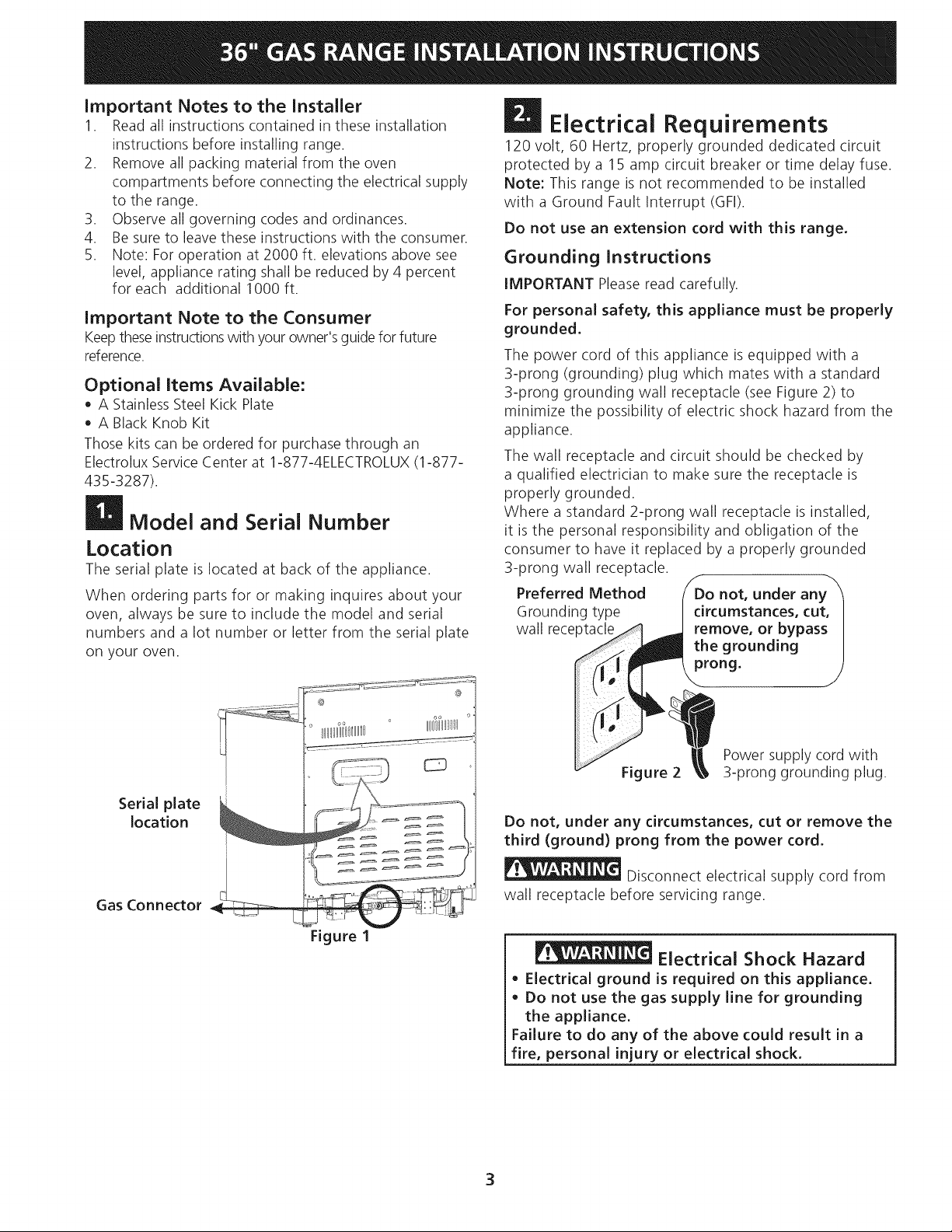
Model and Serial Number
Location
The serial plate is located at back of the appliance.
When ordering parts for or making inquires about your
oven, always be sure to include the model and serial
numbers and a lot number or letter from the serial plate
on your oven.
Electrical Requirements
120 volt, 60 Hertz, properly grounded dedicated circuit
protected by a 15 amp circuit breaker or time delay fuse.
Note: This range is not recommended to be installed
with a Ground Fault Interrupt (GFI).
Do not use an extension cord with this range.
Grounding Instructions
IMPORTANT Pleaseread carefully.
For personal safety, this appliance must be properly
grounded.
The power cord of this appliance isequipped with a
3-prong (grounding) plug which mates with a standard
3-prong grounding wall receptacle (see Figure 2) to
minimize the possibility of electric shock hazard from the
appliance.
The wall receptacle and circuit should be checked by
a qualified electrician to make sure the receptacle is
properly grounded.
Where a standard 2-prong wall receptacle is installed,
it is the personal responsibility and obligation of the
consumer to have it replaced by a properly grounded
3-prong wall receptacle.
Preferred Method
Grounding type
wall rece
Serial plate
location
Gas Connector
Figure 1
Power supply cord with
Figure 2
Do not, under any circumstances, cut or remove the
third (ground) prong from the power cord.
Disconnect electrical supply cord from
wall receptacle before servicing range.
Electrical Shock Hazard
Electrical ground is required on this appliance.
Do not use the gas supply line for grounding
the appliance.
Failure to do any of the above could result in a
fire, personal injury or electrical shock.
3
3-prong grounding plug.
D Gas Supply Installation
When shipped from the factory, this unit is designed
to operate on natural gas with 4" water column for
the cooktop section and 5" water column for the oven
section. Pressure regulators connected to the range
MUST be connected in series with the gas supply line.
The gas connector is located as shown on figure 1. It is
accessible from front of the range.
For proper operation, the maximum inlet pressure
to the regulator should be no more than 14" of water
column pressure (3.5 kPa).
The inlet pressure to the regulator must be at least 1"WC
(.25 kPa) greater than the regulator manifold pressure
setting. The cooktop regulator is set at 4"WC (1.0 kPa)
and the oven section is set at 5"WC for Natural gas; the
inlet pressure must be at least 5" and 6" water column
respectively for cooktop and oven section. For LP/Propane
gas, the regulator must be set for 10" (25.4 cm) water
column (2.5 kPa) manifold pressure; the inlet pressure
must be at least at 11" (27.9 cm) water column (2.75kPa).
The supply line should be equipped with an approved
shutoff valve (see Figures 3 & 4). This valve should be
located in the same room as the range and should be
in a location that allows ease of opening and closing.
Do not block access to the shutoff valve. The valve is for
turning on or shutting off gas to the appliance. Open the
shutoff valve in the gas supply line. Wait a few minutes
for gas to move through the gas line.
The gas supply between the shutoff valve and the
regulator may be connected by rigid piping or by A.G.A./
C.G.A.-approved flexible metallic union-connected
piping where local codes permit use.
The gas supply piping can be through the side wall
of the right cabinet. The right side cabinet is an ideal
location for the main shutoff valve, if the range is
installed within cabinet storage space
Connection to Pressure Regulator
The regulator is already installed on the appliance.
_Do not make the connection too tight.
The regulator is die cast. Overtightening may crack the
regulator resulting in a gas leak and possible fire or
explosion.
The gas supply line to the shutoff valve should be
1/2" or 3/4" solid pipe.
The user must know the location of the main shutoff
valve and have easy access to it.
When using flexible gas conduit on the range, allow
sufficient slack to pull the range outside the cutout for
cleaning or servicing.
NOTE: Do not allow the flexible conduit to get pinched
between the wall and the range.
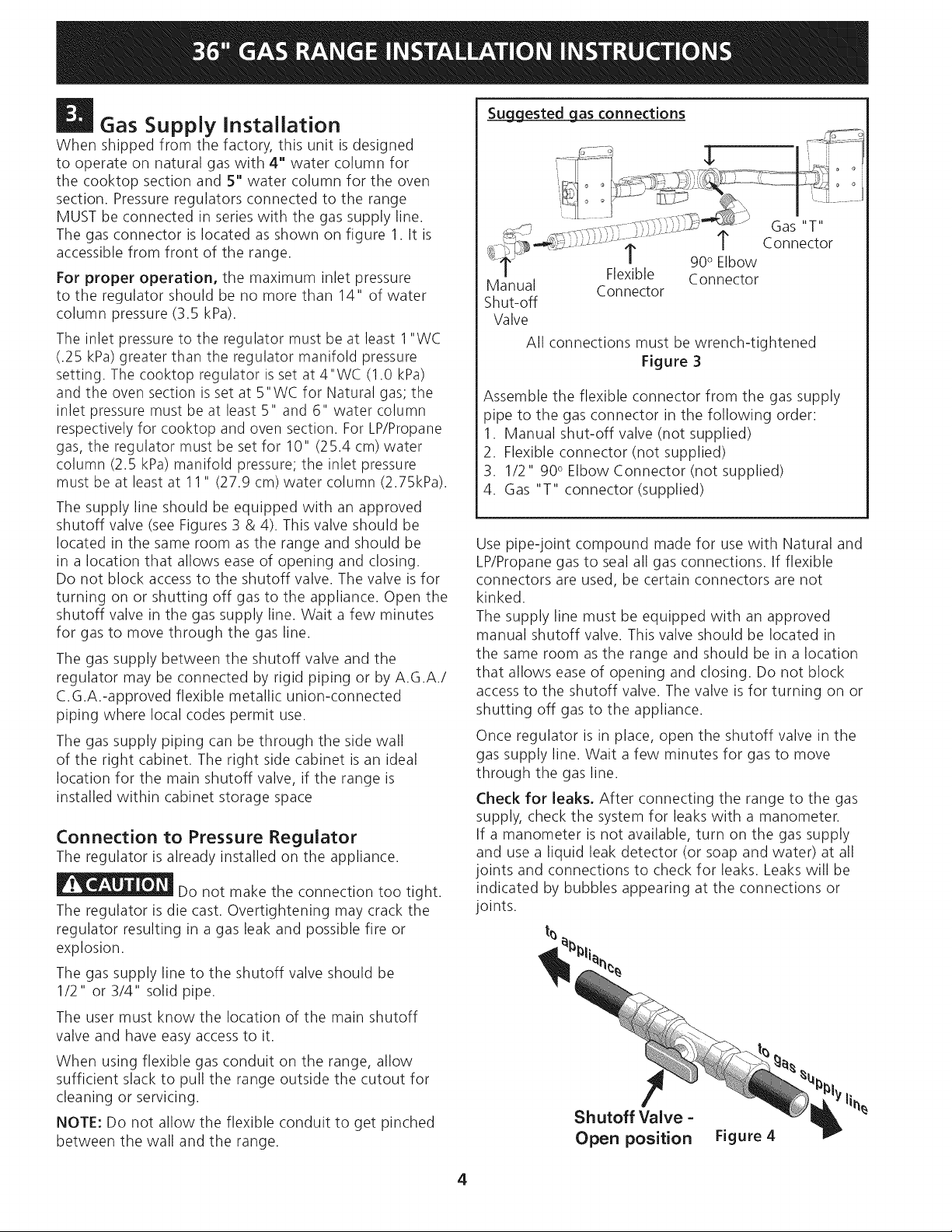
Su__U_gLgestedgas connections
Manual
Shut-off
Valve
All connections must be wrench-tightened
Assemble the flexible connector from the gas supply
pipe to the gas connector in the following order:
1. Manual shut-off valve (not supplied)
2. Flexible connector (not supplied)
3. 1/2" 90° Elbow Connector (not supplied)
4. Gas "T" connector (supplied)
Use pipe-joint compound made for use with Natural and
LP/Propane gas to seal all gas connections. If flexible
connectors are used, be certain connectors are not
kinked.
The supply line must be equipped with an approved
manual shutoff valve. This valve should be located in
the same room as the range and should be in a location
that allows ease of opening and closing. Do not block
access to the shutoff valve. The valve isfor turning on or
shutting off gas to the appliance.
Once regulator is in place, open the shutoff valve in the
gas supply line. Wait a few minutes for gas to move
through the gas line.
Check for leaks. After connecting the range to the gas
supply, check the system for leaks with a manometer.
If a manometer is not available, turn on the gas supply
and use a liquid leak detector (or soap and water) at all
joints and connections to check for leaks. Leaks will be
indicated by bubbles appearing at the connections or
joints.
t_
Flexible Connector
Connector
Figure 3
Shutoff Valve =
Open position
Figure 4
4
r_ "- • '- Do not use a flame to check for leaks
from gas connections. Checking for leaks with a flame
may result in a fire or explosion.
All openings in the wall or floor where the range is to be
installed must be sealed.
Tighten all connections if necessary to prevent gas
leakage in the cooktop or supply line.
Disconnect this range and its individual shutoff
valve from the gas supply piping system during any
pressure testing of the system at test pressures greater
than 1/2 psig (3.5 kPa or 14" water column).
Isolate the range from the gas supply piping system
by closing its individual manual shutoff valve during any
pressure testing of the gas supply piping system at test
pressures equal to or less than 1/2 psig (3.5 kPa or 14"
water column).
LP/Propane Gas Conversion
This appliance can be used with Natural gas or LP/
Propane gas. It is shipped from the factory for use with
natural gas.
If you wish to convert your range for use with LP/
Propane gas, use the supplied fixed orifices located in a
bag containing the literature marked "FOR LP/PROPANE
GAS CONVERSION." Follow the instructions packaged
with the orifices.
The conversion must be performed by a qualified service
technician in accordance with the manufacturer's
instructions and all local codes and requirements. Failure
to follow these instructions could result in serious injury
or property damage. The qualified agency performing
this work assumes responsibility for the conversion.
Failure to make the appropriate
conversion can result in personal injury and property
damage.
Moving the Appliance for
Servicing and Cleaning
Turn off the range line fuse or circuit breakers at the
main power source, and turn off the manual gas shut-off
valve. Make sure the range is cold. Open the oven door.
Lift the range at the front and slide it out of the cut-out
opening without creating undue strain on the flexible
gas conduit. Make sure not to pinch the flexible gas
conduit at the back of the range when replacing the unit
into the cut-out opening. Close the door and switch on
the electrical power and gas to the range.
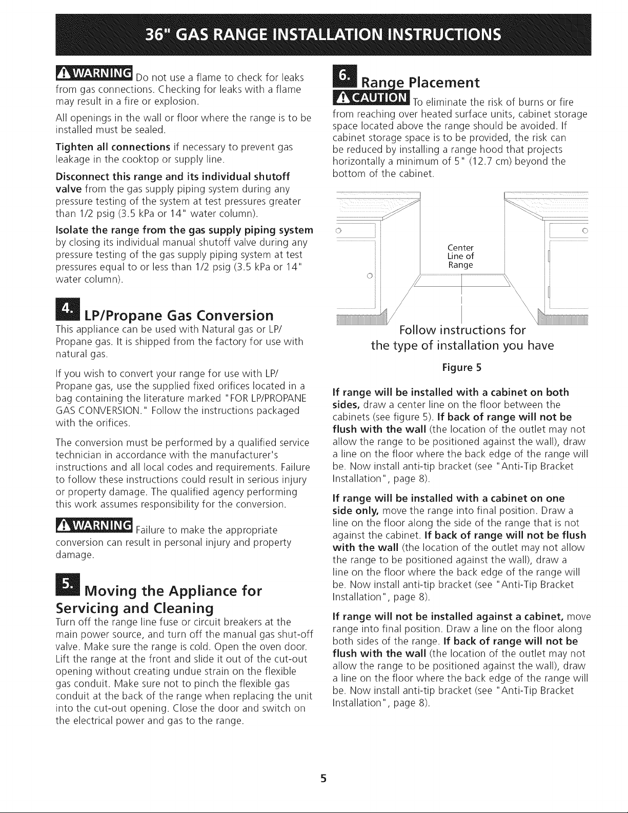
e Placement
To eliminate the risk of burns or fire
from reaching over heated surface units, cabinet storage
space located above the range should be avoided. If
cabinet storage space is to be provided, the risk can
be reduced by installing a range hood that projects
horizontally a minimum of 5" (12.7 cm) beyond the
bottom of the cabinet.
......i ii
J
Center
Line of
Range
i
i
J
i
I \\\\\
Follow instructions for
the type of installation you have
Figure 5
If range will be installed with a cabinet on both
sides, draw a center line on the floor between the
cabinets (see figure 5). If back of range will not be
flush with the wall (the location of the outlet may not
allow the range to be positioned against the wall), draw
a line on the floor where the back edge of the range will
be. Now install anti-tip bracket (see "Anti-Tip Bracket
Installation", page 8).
If range will be installed with a cabinet on one
side only, move the range into final position. Draw a
line on the floor along the side of the range that is not
against the cabinet. If back of range will not be flush
with the wall (the location of the outlet may not allow
the range to be positioned against the wall), draw a
line on the floor where the back edge of the range will
be. Now install anti-tip bracket (see "Anti-Tip Bracket
Installation", page 8).
If range will not be installed against a cabinet, move
range into final position. Draw a line on the floor along
both sides of the range. If back of range will not be
flush with the wall (the location of the outlet may not
allow the range to be positioned against the wall), draw
a line on the floor where the back edge of the range will
be. Now install anti-tip bracket (see "Anti-Tip Bracket
Installation", page 8).
'\
i
Range Installation
1. The back of the range may be installed directly
against the wall.
2. To reduce possible scorching of vertical walls and
to minimize potential fire hazards under abnormal
surface unit use conditions such as high heat or no
pans and to conform to Agency requirements:
- A minimum of 7" (17.8 cm) spacing should be
provided on both sides of the cooktop.
Excessive Weight Hazard
• Use 2 or more people to move and install
range.
• Failure to follow this instruction can result in
back or other injury.
_Check Operation
Refer to the Use and Care Guide and the Electronic Oven
Control Guide packaged with the range for operating
instructions and for care and cleaning of your range.
Remove all packaging from the oven before testing.
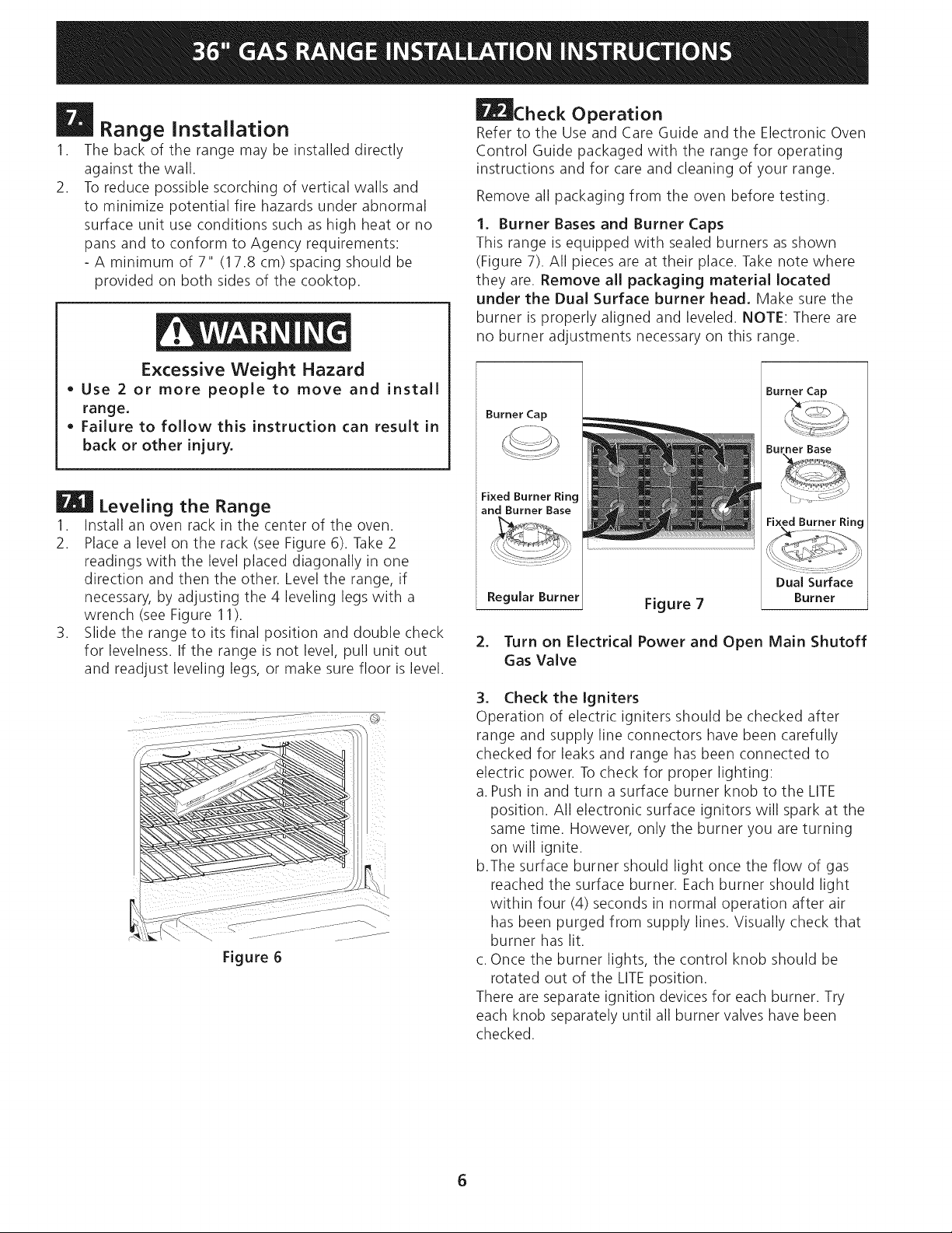
1. Burner Bases and Burner Caps
This range is equipped with sealed burners as shown
(Figure 7). All pieces are at their place. Take note where
they are. Remove all packaging material located
under the Dual Surface burner head. Make sure the
burner is properly aligned and leveled. NOTE: There are
no burner adjustments necessary on this range.
Burner Cap
Burner Cap
k4_--
Burner Base
Leveling the Range
1. Install an oven rack in the center of the oven.
2. Place a level on the rack (see Figure 6). Take 2
readings with the level placed diagonally in one
direction and then the other. Level the range, if
necessary, by adjusting the 4 leveling legs with a
wrench (see Figure 11).
3. Slide the range to its final position and double check
for levelness. If the range is not level, pull unit out
and readjust leveling legs, or make sure floor is level.
Figure 6
Fixed Burner Ring
and Burner Base
Regular Burner
Figure 7
Fixed Burner Ring
Dual Surface
Burner
2. Turn on Electrical Power and Open Main Shutoff
Gas Valve
3. Check the Igniters
Operation of electric igniters should be checked after
range and supply line connectors have been carefully
checked for leaks and range has been connected to
electric power. To check for proper lighting:
a. Push in and turn a surface burner knob to the LITE
position. All electronic surface ignitors will spark at the
same time. However, only the burner you are turning
on will ignite.
b.The surface burner should light once the flow of gas
reached the surface burner. Each burner should light
within four (4) seconds in normal operation after air
has been purged from supply lines. Visually check that
burner has lit.
c. Once the burner lights, the control knob should be
rotated out of the LITEposition.
There are separate ignition devices for each burner. Try
each knob separately until all burner valves have been
checked.
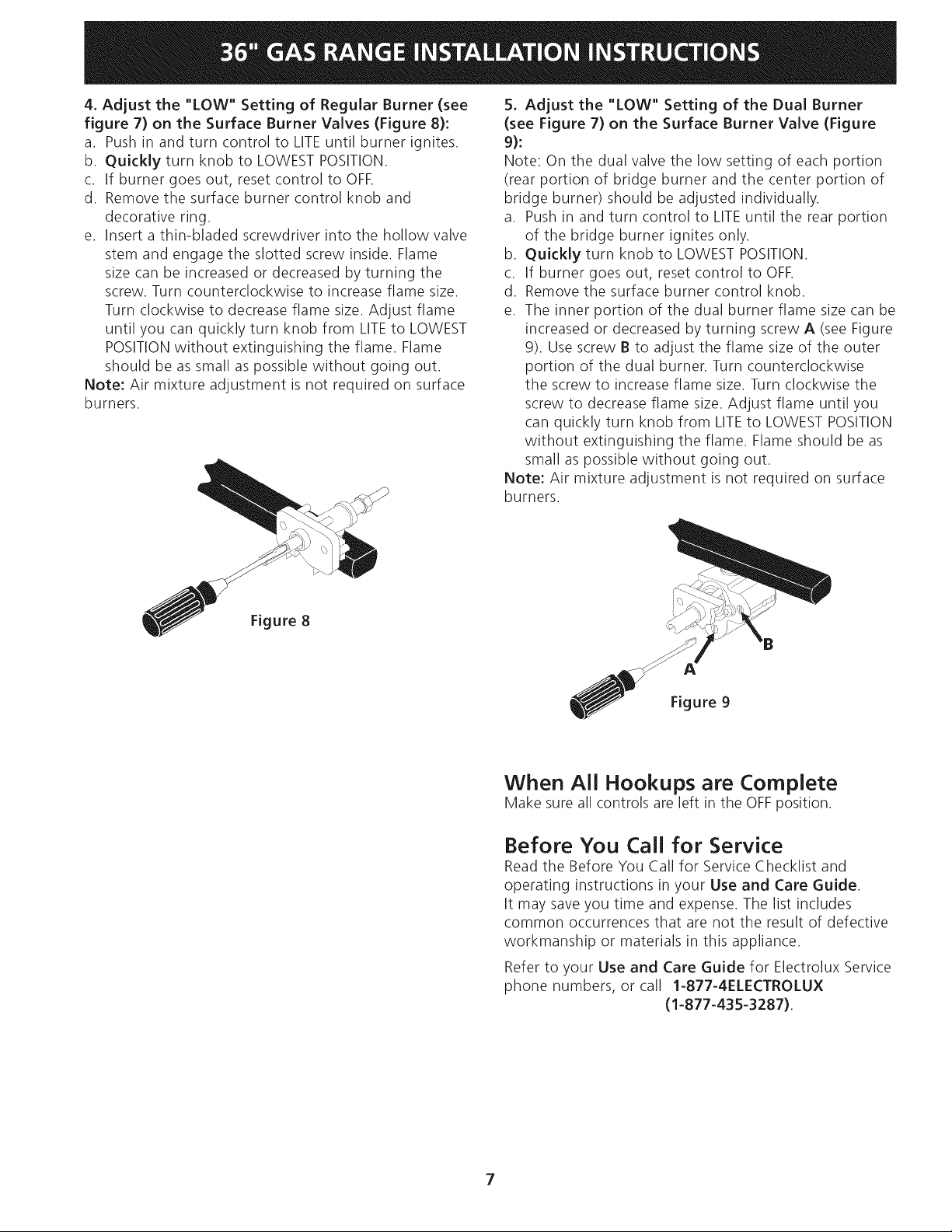
4.Adjustthe "LOW"Settingof RegularBurner(see
figure7)onthe SurfaceBurnerValves(Figure8):
a. Pushinandturncontrolto LITEuntilburnerignites.
b. QuicklyturnknobtoLOWESTPOSITION.
c. If burnergoesout,resetcontroltoOFF.
d. Removethesurfaceburnercontrolknoband
decorativering.
e. Insertathin-bladedscrewdriverintothehollowvalve
stemandengagetheslottedscrewinside.Flame
sizecanbeincreasedordecreasedbyturningthe
screw.Turncounterclockwisetoincreaseflamesize.
Turnclockwisetodecreaseflamesize.Adjustflame
untilyoucanquicklyturnknobfromLITEto LOWEST
POSITIONwithoutextinguishingtheflame.Flame
shouldbeassmallaspossiblewithoutgoingout.
Note:Airmixtureadjustmentisnotrequiredonsurface
burners.
5. Adjustthe"LOW"Settingof theDualBurner
(seeFigure7)on theSurfaceBurnerValve(Figure
9):
Note:Onthedualvalvethelowsettingofeachportion
(rearportionof bridgeburnerandthecenterportionof
bridgeburner)shouldbeadjustedindividually.
a. Pushinandturncontrolto LITEuntiltherearportion
ofthebridgeburnerignitesonly.
b. QuicklyturnknobtoLOWESTPOSITION.
c. If burnergoesout,resetcontroltoOFF.
d. Removethesurfaceburnercontrolknob.
e. Theinnerportionofthedualburnerflamesizecanbe
increasedordecreasedbyturningscrewA (seeFigure
9). Use screw B to adjust the flame size of the outer
portion of the dual burner. Turn counterclockwise
the screw to increase flame size. Turn clockwise the
screw to decrease flame size. Adjust flame until you
can quickly turn knob from LITEto LOWEST POSITION
without extinguishing the flame. Flame should be as
small as possible without going out.
Note: Air mixture adjustment is not required on surface
burners.
Figure8
Figure 9
When All Hookups are Complete
Make sure all controls are left in the OFFposition.
Before You Call for Service
Read the Before You Call for Service Checklist and
operating instructions in your Use and Care Guide.
It may saveyou time and expense. The list includes
common occurrences that are not the result of defective
workmanship or materials in this appliance.
Refer to your Use and Care Guide for Electrolux Service
phone numbers, or call 1-877-4ELECTROLUX
(1-877-435-3287).
7

Important Safety Warning
To reduce the risk of tipping of the range, the range
must be secured to the floor by the properly installed
anti-tip bracket and screws packed with the range. These
parts are located in a plastic bag in the oven. This gas
range has two brackets. Failure to install the bracket will
allow the range to tip over if excessive weight is placed
on an open door or if a child climbs upon it. Serious
injury might result from spilled hot liquids or from the
range itself.
Follow the instructions below to install the anti-tip
bracket.
If range is ever moved to a different location, the anti-
tip bracket must also be moved and installed with the
range.
Tools Required:
5/16" (8 mm) Nut driver or Flat Head Screwdriver
Adjustable Wrench
Electric Drill
3/16" (4.8 mm) Diameter Drill Bit
3/16" (4.8 mm) Diameter Masonry Drill Bit (if installing in
concrete)
Anti-Tip Bracket Installation
1. The anti-tip bracket must be installed on the right
and left side at back of the range.
2. The anti-tip bracket supports are attached to the floor
at the back. When fastening to the floor, be sure that
screws do not penetrate electrical wiring or plumbing.
The screws provided will work in either wood or
concrete.
3. Unfold paper template and place it flat on the floor
with the back and side edges positioned exactly
where the back and sides of range will be located
when installed. (Use the diagram in figure 10 to
locate bracket if template is not available.)
J .......... -.
J
/
4. Mark on the floor the location of the mounting holes
shown on the template (right and left position). For
easier installation, 3/1 6" (4.8 mm) diameter pilot
holes 1/2" (1.3 cm) deep can be drilled into the floor.
5. Remove template and place bracket on floor (see
figure 10). Line up holes in bracket with marks
on floor and attach the bracket using the screws
provided. Brackets must be secured to solid floor. If
attaching to concrete floor, first drill 3/16" (4.8 mm)
dia. pilot holes using a masonry drill bit.
6. Level range if necessary, by adjusting the 4 leveling
legs with an adjustable wrench. Loosen the screw
which fixes the decorative leg and lift it to reach the
leveling leg. Turn the leveling leg counterclockwise
to raise the range or clockwise to lower the range
(see Figure 11). Replace the decorative legs at your
convenience.
7. Before sliding the range to its final position; take note
of the serial and model numbers for future reference.
Slide range into place making sure rear leg is trapped
by the bracket. Range may need to be shifted slightly
to one side as it is being pushed back to allow rear
leg to align with bracket.
8. After installation, visually verify that the anti-tip
brackets are engaged.
. ii- .... ....................,
:: ...... ./I.......
Figure10 /i- .........
Note: Install the anti-tip bracket on the tic ht and left side
Figure 11
36" Range 14 5/16 (36.4 cm) 1 5/8 (4.1 cm)
8

LA INSTALACION Y EL SEP,VICIO DEBEN SEP,EFECTUADOS POP, UN INSTALADOP, CAUFICADO.
IMPOP,TANTE: GUAP,DE ESTAS INSTP,UCCIONES PAP,A USO DEL INSPECTOR LOCAL DE
ELECTP,ICIDAD.LEA Y GUAP,DE ESTAS INSTP,UCCIONES PAP,A P,EFEP,ENCIA FUTUP,A.
OBSERVE CODIGOS GOBEP,NANTES Y OP,DENANZAS.
l' "'' ' " SilainformaciOncontenidaenestemanualnoesseguidaexactamente,
puede ocurrir un incendio o explosion causando daffos materiales, lesion personal o la
muerte.
PARA SU SEGURIDAD:
-- No almacene ni utilice gasolina u otros vapores y liquidos inflamables en la proximidad
de _ste o de cualquier otto electrodom_stico.
-- QUE DEBE HACER SI PERCIBEUN OLOR A GAS:
• No trate de encender ningun electrodom_stico.
No toque ningun interruptor el_ctrico; no use ningun telefono en su edificio.
Marne a su proveedor de gas desde el telefono de un vecino. Siga las instrucciones del
proveedor de gas.
Si no Iogra comunicarse con su proveedor de gas, Ilame al departamento de bomberos.
-- La instalaciOn y el servicio de mantenimiento deben set efectuados por un instalador
calificado, la agencia de servicio o el proveedor de gas.
35 7/8" Min.
(91.1 cm Min.)
Nora: Para
electrodomesficos
instalados en
el estado de
Massachusetts.
Veap_gina 12.
Si hay una pared:
7" Min.
(17:8 cm Min,)
lad0 izqL
Yea
Nota
(45.7 cm Min.
13" Max.
(33 cm Max.)
-Si hay una pared:
7" Min.
(17.8 cm Min.)
F
NOTA: Un espacio minimo de 28" (71.1 cm) entre la
Tomacorriente
pared puesto a
tierra
superficie de la estufa y el fondo del armario cuando el
fondo del armario de madera o metal est_qprotegido
pot no menos de 1/4" (0.64 cm) de madera resistente al
fuego cubierta pot una I_imina met_qlicade MSG, nOmero
28, 0.01 5" (0.4 mm) de acero inoxidable, 0.024" (0.6
mm) de aluminio, 6 0.02" (0.5 mm) de cobre.
No pellizque el cord6n el_ctrico entre la estufa y la pared.
No selle la estufa a los armarios laterales.
Un espado minimo de 34" (86.4 cm) cuando el
armario no est_ protegido.
A. ALTURA , B:ANCHO C;PROFUNDIDAD D,ALTURADELA
' ALFRENTEDELA CUBIERTA
ESTUFA I
415/8"(105.7cm)Min. 35 7/8" 27Y2" 353/4"(90.8cm) Min.
425/8"(108.3cm)Max. (91.1cm) (69.9cm) 363/4"(93.3cm)Max.
E.PROFUNDIDNI] F.ALTURADE GI ANCHO
CONPUERTA MOSTRABOR MJNIMOPARA
ABIERTA LAABERTURA
47 3/8" 36"(91.4 cm) Standard 36 1/16"
(120.3 cm) 35 3/4" (90.8 cm) Min. (91.6 cm)
El diagrama del cableado de este modelo est_qincluido en esta manual (vea la pagina 20)
Impreso en los Estados Unidos English - pages 1-8; EspaBol - p_iginas9-16; Notas - p_iginas 17-19;
Diagrama de la instalaci6n al_imbrica - p_igina 20
P/N318201779 (1006) Rev.A

IMPORTANTES INSTRUCCIONES
DE SEGURIDAD
Instalaci0n de esta estufa debe cumplir con todos losc0digos
locales,o enausencia de c0digos localescon el C0digo
Nacional de GasCombustible ANSIZ223.1/NFPA no.54.
La instalaci0n de aparatos diseflados para instalaci0n
en casasprefabricadas (m0viles)debe conformar con el
Manufactured Home Construction and Safety Standard,
titulo 24CFR,parte 3280 [Anteriormente el FederalStandard
for Mobil Home Construction and Safety, titulo 24, HUD
(parte 280)] o cuando tal est_indarno se aplica, el Standard
for Manufactured Home Installation 1982 (Manufactured
Home sites,Communities and Setups), ANSI Z225.1/NFPA
501A-edici0n m_qsreciente, o con los c0digos locales.
Esta estufa ha sido diseflada y certificada por el organismo
CSA Internacional. Como en cualquier electrodom@stico
donde se use gas y se genere cierto calor, existen diversas
precauciones de seguridad que deben ser seguidas. Usted
encontrar_i esta lista de precauciones en el manual de Uso y
Cuidado, por favor I@alascuidadosamente.
• Asegurese de que la estufa sea instalada y
conectada a tierra en forma apropiada pot un
instalador calificado o pot un t_cnico.
Esta estufa debe set el_ctricamente puesta a
tierra de acuerdo con los codigos locales, o en su
ausencia, con el Codigo El_ctrico Nacional ANSI/
NFPA No. 70, _ltima edicion.
Asegerese de que el material que recubre las
paredes alrededor de la estufa, pueda resistir el
calor generado pot la estufa.
Antes de instalar la estufa en un _rea cuyo piso
este recubierto con lin61eo u otro tipo de piso
sint_tico, asegurese de que _stos puedan resistir
una temperatura de pot Io menos 90°F sobre la
temperatura ambiental sin provocar encogimiento,
deformacion odecoloraci6n. No instale la estufa
sobre una alfombra al menos que coloque una plancha
de material aislante de por Io menos 1/4 pulgada, entre
la estufa y la alfombra.
No obstruya el flujo del aire de
combusti6n en la ventilacion del homo ni tampoco
alrededor de la base o debajo del panel inferior
delantero de la estufa. Evite tocar las aberturas o _ireas
cercanas de la ventilaci0n, ya que pueden estar muy
calientes durante el funcionamiento del homo. La estufa
requiere aire fresco para la combustiOn apropiada de los
quemadores.
Nunca deje ni_os solos o
desatendidos en un area donde un electrodom_stico
esta siendo usado. A medida que los niflos crecen,
ens_fleles el uso apropiado y seguro para todos los
electrodom_sticos. Nunca deje la puerta del homo abierta
cuando la estufa est_qdesatendida.
No se pare, apoye o siente en las
puertas o cajones de esta estufa pues puede resultar
en serias lesiones y puede tambien causar da_o a la
estufa.
No almacene articulos que puedan interesar a los
ni_osen Iosgabinetessobrelaestufa. Los niflos
pueden quemarse seriamente tratando de trepar a la
estufa para alcanzar estos articulos.
Los gabinetes de almacenamiento sobre la estufa
deben evitarse, para eliminar la necesidad de
tenet que pasar sobre los elementos superiores de
la estufa para Ilegar a ellos,
Ajuste el tama_o de la llama de los quemadores
superiores de tal manera que _sta no sobrepase el
borde de los utensilios de codnar. La llama excesiva
es peligrosa.
No use el homo como espado de almacenaje. Esto
crear_i una situaci0n potencialmente peligrosa.
Nunca use la estufa para calentar el cuarto. El uso
prolongado de la estufa sin la adecuada ventilaci0n
puede resultar peligroso.
No almacene ni utilice gasolina u otros vapores y
liquidos inflamables en la proximidad de _ste o de
cualquier otto electrodom_stico electrico. Puede
provocar incendio o explosiOn.
En caso de una interruptiOn del servicio el@ctrico, es
posible de encender los quemadores de superficie a
mano. Paraencender un quemador de superficie, acerque
un fOsforo encendido a la cabezal del quemador, y gire
r_ipidamente el botOn de control de superficie a Med.
Tenga cuidado al encender los quemadores a mano.
Retire el sarten asador, alimentos o cualquier otto
utensilio antes de ajustar un ciclo de auto=limpieza
en el homo. Limpie el exceso de derrames. Siga las
instrucciones en manual de Uso y Cuidado.
A diferencia de otras cubiertas a gas, ESTA
CUBIERTA no es removible, No intente remover esta
cubierta.
Instrucciones especiales para los electrodomesticos instalados
en el estado de Massachussets: Este electrodomestico puede
ser solamente instalado en el estado de Massachussets por
un plomero calificado o instalador de gas con licencia en el
estado de Massachussets. Cuando se utilice un conector flexi-
ble de gas, este no debe de exceder 3 pies (36 pulgadas) de
largo. Una valvula manual de tipo "T" debe de instalarse en la
finea de alimentaciOn de gas hacia este electrodomestico.
• Todas las estufas pueden volcarse.
• Estopodria resultar en lesiones personales.
• Instale el dispositivo antivuelco provisto
con esta estufa.
Para reducir el riesgo de que se vuelque la
estufa, hay que asegurarla adecuadamente
colocando Los soportes antivuelco que se
proporcionan. Para comprobar si estos est_qninstalados y
apretados correctamente, tome el horde trasero superior
de la estufa y cuidadosamente inclinela hacia adelante
para asegurarse que la estufa est@anclada.
10

Notas importantes para el Instalador
1. Leatodas lasinstrucciones contenidas en este manual
antes de instalar la estufa.
2. Saque todo el material usado en elempaque del
compartimiento del homo antes de conectar el
suministro el_ctrico a la estufa.
3. Observe todos los c6digos y reglamentos pertinentes.
4. Deje estas instrucciones con el comprador.
5. Nota: Para el correcto funcionamiento en lugares
superiores a los 2000 ft, el r_gimen del mecanismo debe
reducirse un 4% pot cada 1000 ft sobre el nivel del mar.
Nota Importante para el Consumidor
Conserve estas instrucciones y el Manual del Usuario para
referencia futura.
Articuios Disponibles Opcionales:
• Una Kick plata de Acero Inoxidable.
• Un empaque de perillas negro.
Estosjuegos se pueden ordenar para comprar mediante
Service Center 1-877-4ELECTROLUX (1-877-435-3287).
Ubicacion del Numero de Modelo y
de Serie
La placa de serie se encuentra en la parte trasera de la es-
tufa
Cuando haga pedidos de repuestos o solicite informaci6n
con respecto a su estufa, est_ siempre seguro de incluir
el n0mero de modelo y de serie y el n0mero o letra del
Iote de la placa de serie de su estufa.
Requisitos electricos
120 voltio, 60 Hertzio, circuito dedicado apropiadamente
puestos a tierra protegido pot un circuito de amperio
o fusible de demora de tiempo de 15 amp. Nota: no
es recomendado instalarlo con un Interruptor (GFI)de
puesta a tierra.
No utilice una extension con esta estufa.
Instrucciones de puesta a tierra
IMPORTANTE Por favor lea con cuidado.
Para la seguridad personal, este aparato debe ser
puesto a tierra apropiadamente.
El cable del suministro el_ctrico de esta estufa est,1
equipado con un enchufe de tres patillas (para puesta a
tierra) que coincida con un enchufe de pared est_indar
con puesta a tierra de tres patillas para minimizar la
posibilidad que se produzcan descargas el_ctricas.
El cliente deber_i encargar a un t_cnico para asegurarse
de que el enchufe se encuentra debidamente conectado
a tierra y polarizado.
En lugares en los que aya un enchufe de pared est_indar
de dos patillas, el cliente tendr_i responsabilidad directa
y la obligaci6n de reemplazarlo pot un enchufe de pared
de tres patillas debidamente cableado a tierra.
M_todo preferido
Enchufe de pared
con toma de
tierra
No corte, retire
o derribe,
bajo ninguna
circunstancia, la
patilla de la toma de
tierra del enchufe
Placa de
serie
Conector
de gas
®
o
Figura 1
@
o
o
Cable de suministro
el_ctrico con enchufe
con toma de tierra
Figura 2
Bajo ninguna circunstanda, corte, retire o derribe
la tercera patilla (de toma de tierra) del cable del
suministro de energia electrica.
Desenchufa el cable del suministro
de energia el_ctrica del enchufe de pared antes de
mantener la estufa.
Riesgo de Choque Electrico
Se requiere una conexiOn a tierra en este
electrodom_stico.
No utilizar la alimentaciOn de gas para la
conexiOn a tierra.
El no seguir cualquiera de las advertendas aqui
mencionadas, podria resultar en un incendio,
choque electrico o lesiones.
11
Instalacion de la alimentacion de gas
Cuando esta unidad ha sido enviada de la fabrica estate1
ajustada para operar con gas natural a 4" de columna de
agua en la secci6n de lacubierta y 5" de columna de agua
en lasecci6n del homo. Reguladores de presi6n conecta-
dos a la estufa DEBENde estar conectados en serie con
la tuberia de suministro de gas. La conexi6n con el gas se
encuentra como es mostrado en la figura 1. Esaccesible
por el frente de la estufa.
Para la operaci6n adecuada, la presi6n m_iximade en-
trada al regulador no debe de ser mas de 14" de presi6n
de columna de agua (3.5 kPa).
La presi6n de entrada el regulador debe de ser por Io
menos 1" de c.d.a (.25kPa) m_isgrande que el ajuste de
la wilvula distribuidora. El regulador de la cubierta ha sido
ajustado para gas natural a 4" c.d.a (1.0kPa) y la secci6n
del homo a 5" c.d.a. Lapresi6n de entrada debe de ser
de al menos 5" y 6" columna de agua para la cubierta y la
secci6n del homo respectivamente. Para propano liquido
a 10 pulgadas de presi6n para la wilvula distribuidora (2.5
Kpa) lapresi6n de entrada debe ser por Io menos de 11
pulgadas (2.75 kpa).
La tuberia deber_i ser equipada con una wilvula de cierre
aprobada (vea Figura 3 & 4). Esta wilvula debe ubicarse
en la misma habitaci6n que la estufa en un lugar que
permita una una facilidad de abrir y cerrar. No bloqu_e
el acceso a la wilvula de cierre. La wilvula abre o cierra
es para abrir o cerrar el suministro de gas al aparato.
Abra la wilvula de cierre en la linea de suministro de gas.
Espere unos minutos a que el gas pase por el tubo.
El suministro de gas entre la wilvula de cierre y el
regulador se puede conectar con tuberia rigida o con
tuberia flexible uni6n met_ilica conectada y aprobada por
la AGA/CGA donde los c6digos locales permiten.
La tuberia del suministro de gas puede pasar por la pared
lateral del armario derecho. Elarmario lateral derecho es
un lugar ideal para la wilvula de cierre principal.
Conexion del regulador
El regulador esta instalado en el electrodom_stico.
"I" Conector codo de
V_ilvula flexible
de cierre
manual
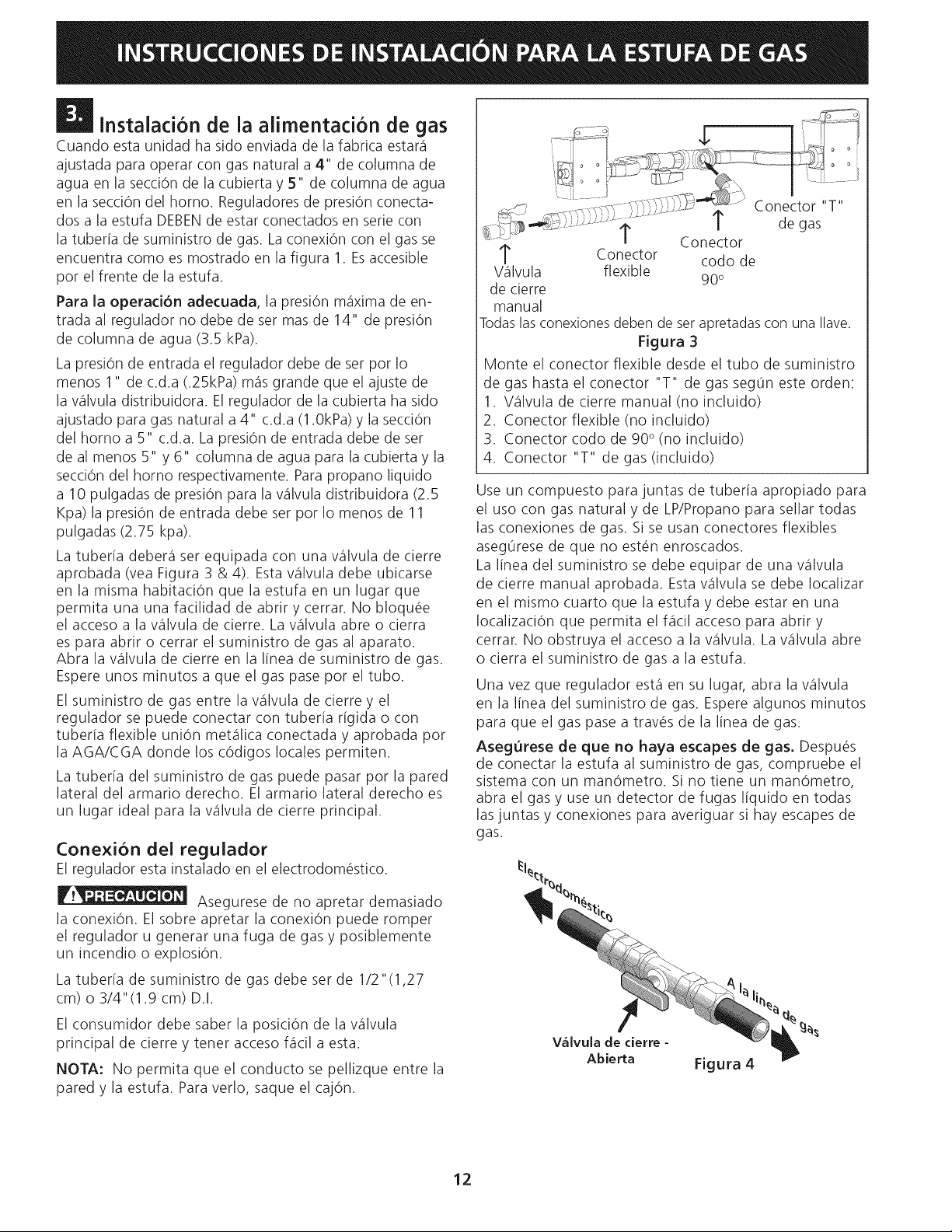
Todaslasconexionesdeben de set apretadascon una Ilave.
Figura 3
Monte el conector flexible desde el tubo de suministro
de gas hasta el conector "T" de gas seg0n este orden:
1. %ilvula de cierre manual (no incluido)
2. Conector flexible (no incluido)
3. Conector codo de 90° (no incluido)
4. Conector "T" de gas (incluido)
Use un compuesto para juntas de tuberia apropiado para
el uso con gas natural y de LP/Propano para sellar todas
las conexiones de gas. Si se usan conectores flexibles
aseg0rese de que no est6n enroscados.
La linea del suministro se debe equipar de una wilvula
de cierre manual aprobada. Esta wilvula se debe Iocalizar
en el mismo cuarto que la estufa y debe estar en una
Iocalizaci6n que permita el flicil acceso para abrir y
cerrar. No obstruya el acceso a la wilvula. Lawilvula abre
o cierra el suministro de gas a la estufa.
Una vez que regulador est,1en su lugar, abra la wilvula
en la linea del suministro de gas. Espere algunos minutos
para que el gas pase a trav6s de la linea de gas.
AsegOrese de que no haya escapes de gas, Despu_s
de conectar la estufa al suministro de gas, compruebe el
sistema con un manOmetro. Si no tiene un manOmetro,
abra el gas y use un detector de fugas liquido en todas
las juntas y conexiones para averiguar si hay escapes de
gas.
90 °
Asegurese de no apretar demasiado
la conexi6n. El sobre apretar la conexi6n puede romper
el regulador u generar una fuga de gas y posiblemente
un incendio o explosi6n.
La tuberia de suministro de gas debe ser de 1/2"(1,27
cm) o 3/4"(1.9 cm) D.I.
El consumidor debe saber la posici6n de la wilvula
principal de cierre y tener acceso f_icil a esta.
NOTA: No permita que el conducto se pellizque entre la
pared y la estufa. Para verlo, saque el caj6n.
12
V=ilvula de cierre -
Abierta
Figura 4

No use flama para verificar que no
hayan p_rdidas de gas. Lacomprobaci0n de p_rdidas
de gas con una flama puede resultar en un incendio o
explosion.
Se debe sellar todas las aberturas en la pared o el
piso donde la estufa este instalada.
Apriete todas las conexiones si hace falta para
prevenir fugas de gas en la superficie de la estufa o en la
linea de suministro.
Desconecte esta estufa y su valvula individual de
derre del sistema del siministro de gas durante cualquier
prueba de presiOn de ese sistema a presiones mayores de
1/2 psig (3.5 kPa o 14"(35,56 cm) columna de agua).
Aisle la estufa del sistema del suministro de gas
cerrando su wilvula manual de cierre individual durante
cualquier prueba de presiOn del suministro del gas
a presiones iguales a menos de 1/2 psig (3.5 kPa o
14"(35,56 cm) columna de agua).
Conversi6n para uso de Propano
Liquido
Este aparato puede set usado con gas natural o propano
liquido. Ha sido ajustado en la f_ibrica para operar con
gas natural solamente.
Si desea convertir su estufa para uso con propano
liquido, use las esperas provistas ubicados en el bolso
que contiene la literatura titulada "FOR LP/PROPANE GAS
CONVERSION". Siga las instrucciones que vienen con las
esperas.
La conversion debe efectuarse por un t_cnico de
servicio capacitado, de acuerdo con las instrucciones
del fabricante y con todos los cOdigos y requisitos
de las autoridades correspondientes. El no seguir las
instrucciones podria dar como resultado lesiones graves
oda_osalapropiedad. Elorganismoautorizadopara
Ilevar a cabo este trabajo asume la responsabilidad de la
conversion.
La falta de una conversion apropiada
puede resultar en lesiones graves y dahos a la propiedad.
Estufa - Co[ocaci6n
Para eliminar el riesgo de quemaduras
o fuego pot el contacto de superficies sobrecalentadas,
cualquier espacio de almacenaje en los gabinetes situados
sobre la estufa debe set evitado. Si un espacio de
almacenaje debe de set proporcionado, el riesgo puede set
reducido instalando una campana de estufa que proyecte
horizontalmente e un m[nimo de el 5" (12.7 cent[metros).
CL
de la
estufa
[ '\\
Siga las instrucciones
para eltipo de instalaciOn que usted tenga
Figura 5
Si la estufa se va a instalar con armarios laterales,
marque el centro de la abertura del armario en el piso (vet
la figura 5). Si la parte trasera de la estufa no estar_
a ras con la pared (la ubicacion del tomacorriente puede
que no permita que la estufa se pegue a ras con la pared),
marque el piso donde estara el borde trasero de la estufa.
Ponga el patron en el piso, alineando la I[nea del centro
del patron con la marca en el centro de la abertura del
armario. Ponga el borde trasero del patron a ras contra la
pared trasera o la I[nea marcada para la parte de atras de la
estufa.
Si la estufa se va a instalar con un armario en un s6lo
un lado, mueva la estufa a su posicion final. Marque el piso
pot el lado de la estufa que no estara contra el armario. Si
la parte trasera de la estufa no esta al ras con la pared
(la ubicacion del tomacorriente puede que no permita que la
estufa se pegue al ras con la pared), marque el piso donde el
borde trasero de la estufa estara. Ponga el patron en el piso
y alinee el lado del patron con la I[nea marcada en el piso. All-
nee la parte trasera del patron con la pared trasera o la I[nea
marcada para la parte de atras de la estufa.
F
La mudanza del aparato para
reparaciones o [impieza
Corte la corriente el_ctrica a la estufa a la fuente de poder
principal, y cierre la wilvula manual de gas. Aseg0rese de
que la estufa est_ fria. Abra la puerta del homo. Levante el
frente de la estufa y deslicela fuera de la abertura sin crear
tension desmedida sobre el conducto flexible de gas. Ase-
g0rese de no pellizcar el conducto flexible de gas detr_is
de la estufa al reinstalar la unidad en la abertura. Cierre la
puerta y abra el gas y la corriente el_ctrica a la estufa.
Si la estufa no ser_ instalada junto a un armario, mueva
la estufa a su posicion final. Marque el piso pot los dos lados
de la estufa. Si la parte trasera de la estufa no estar_ a
ras con la pared (la ubicacion del tomacorriente puede que
no permita que la estufa se pegue a ras con la pared), marque
en el piso donde el borde trasero de la estufa estara. Ponga
el patron en el piso y alinee los lados del patron con las I[neas
marcadas en el piso. Alinee la parte trasera del patron con la
pared trasera o la I[nea marcada para la parte trasera de la
estufa.
13

Instalad6n de la estufa
1. La parte trasera de la estufa puede ser directamente
instalada a ras con la pared trasera de la estructura.
2. Para reducir posibles marcas o rayas de las paredes
verticales y minimizar los riesgos de choques
el_ctricos en caso de condiciones de uso anormales
como alto calor o no cazuelas, y para conformar a
los requisitos de A.G.A:
Un espacio minimo de 7" (17.8 cm) debe de ser
provisto en ambos lados de la plancha de cocinar.
Pe[igro de Peso Excesivo
• Use 2 personas o re,is para mover e instalar la
estufa.
• Si no cumple con esta instrucd6n, usted podr,i
lesionarse la espalda u otra parte de su cuerpo.
| Cornprobad6n del Fundonamiento
Consulte el Manual del Usuario induido con la estufa
para instrucciones de operaci6n y instrucciones para el
cuidado y limpieza de su estufa.
Quite todo el embaque de la unidad antes de
comprobarla.
1, Bases y tapas de los quernadores,
Esta estufa esta equipada con quemadores sellados como
se muestra m_qsabajo (Figura 7). Todas las piezas est_in
en su lugar. Tome nota en donde est_in. Quite todo el
material de proteccion Iocalizado bajo la cabeza del
quemador de dual, NOTA: No hace falta ning0n ajuste
de quemador en esta estufa.
Tapa de quernador
Tapa de quemador
Base de quemador
m
Nivelaci6n de ia estufa
1. Coloque una parrilla del homo en el centro del
homo.
2. Ponga un nivel sobre la parrilla (figura 6). Ponga
un nivel sobre la parrilla. Tome dos lecturas con
el nivel puesto diagonalmente en una direcci6n y
despu_s en la otra. Nivele la estufa, si es necesario,
ajustando las 4 patas niveladoras con una Ilave de
tuercas (vea la figura 11).
3. Deslice la estufa a su posici6n final y verifique dos
veces la nivelaci6n de la unidad. Si la estufa no
esta nivelada, jale la unidad y reajuste las patas
niveladoras, o aseg0rese que su piso este nivelado.
Figura 6
Anillo fijo y base
fijo de quemador
Quemador
regular
Anillo fijo de
Quemador
doble
Figura 7
2. Endenda la corriente electrica y abra la v&lvula
principal de alirnentad6n.
3. Comprobacion de los Encendedores
El funcionamiento de las bujfas electr0nicas desde set
comprobado una vez que los conectores del suministro de
gas ban sido verificados y no exista ning0n tipo de fuga. Y el
suministro de electricidad se conecte a la estufa.
Para verificar un encendido correcto:
A, Presione y gire a una perilla a la posicion de LITE. Todos
las bujfas electronicas chispear_in al mismo tiempo. Sin
embargo, solamente el quemador que usted se est,1girando
encenderZ
B. El quemador se deber_i encender en cuatro (4) segundos
para un funcionamiento normal, luego de que el aire
haya sido purgado de la tuber[a de suministro de
gas. Controle visualmente que el quemador se hay
encendido.
C. Luego que el quemador se haya encendido, la perilla
debe set girada fuera de la posicion LITE.
Cada quemador tiene su encendedor individual. Controle
las perillas separadamente hasta que todas las wilvulas
hayan sido controladas.
14

4. Ajuste bajo ('"LO"") para la valvula de los quemado-
res de superficie estandar (Figuras 7 y 8)
a. Presione y gire el control hasta la posiciOn LITEpara
prender los quemadores.
b. Gire r_pidamente gire la perilla a la POSICIONMAS
BAJA.
c. Si el quemador seapaga, reajuste el control a OFE
d. Retire la perilla y el anillo del quemador de superficie.
e. Inserte un destornillador fino-aplanado en el orifico del
wistago de la wilvula e inserte en el tornillo ranurado.
El tamaho de la llama puede aumentarse o disminuirse
d_indole vuelta al tornillo. D_ vuelta en sentido opuesto
alas manecillas del reloj para aumentar el tamaho de
la llama. D_ vuelta en sentido alas manecillas del reloj
para disminuir la llama. Ajuste la llama hasta que usted
puede dar vuelta r@idamente a la perilla de la posici6n
LITEa la POSICIONMAS BAJA sin extinguir la llama.
La llama debe ser tan pequeha como sea posible sin
apagarse.
Nota: Elajuste de la mezcla del aire no se requiere en
los quemadores de superficie
5. Ajuste bajo ""LOW"" para la v&Ivula de quemador
de superfide Dual (vea Figura 7 y 9)
Nota: En la wilvula de quemador triple el ajuste <<LOW>>
de cada porci6n (porci6n posterior del quemador puente
y la porci6n de centro del quemador del puente) sedebe
ajustar individualmente.
a. Presione y gire el control a la posici6n LITEhasta que la
porci6n posterior del quemador puente se encienda.
b. Gire r_pidamente a la perilla a la POSICIONMAS BAJA.
c. Si el quemador se apaga, reajuste elcontrol a OFR
d. Retire la perilla del quemador de superficie.
e. Eltamaho de laflama de la porci6n posterior del que-
mador puente puede aumentarse o disminuirse d_indo-
le vuelta al tornillo A (vea Figura 9). Utilice el tornillo B
para ajustar el tamaho de la llama de la porci0n central
del quemador puente o del quemador triple. D_ vuelta
en sentido opuesto de las manecillas del reloj para
aumentar el tamaho de la llama. D_ vuelta en sentido
a las manecillas del reloj para disminuir la llama. Ajuste
la llama hasta que usted puede dar vuelta r@idamente
a laperilla de la posici6n LITEa la POSICION MAS BAJA
sin extinguir la llama. La llama debe ser tan pequeha
como sea posible sin apagarse.
Nota: Elajuste de la mezcla del aire no se requiere en los
quemadores de superficie.
Figura 8
Figura 9
Despues de Terminar la Instalacion
Aseg0rese de que todos los controles est_n en la posiciOn
OFF(apagada).
Antes de Llamar al Servicio
Lea la secciOn Lista de control de averias en su Manual
del Usuario. Esto le podr_i ahorrar tiempo y gastos. Esta
lista incluye ocurrencias comunes que no son el resultado
de defectos de materiales o fabricaci6n de este artefacto.
Re%rase a su manual de Uso y Cuidado para la lista tele-
f6nica del servicio o Ilame al 1-877-4ELECTROLUX (1-877-
435-3287).
15

Importante Advertencia de Seguridad
Para reducir el riesgo de que la estufa se vuelque, es
necesario asegurarla al piso instalando los soportes
antivuelco y los tornillos suministrados con la estufa. Las
piezas se encuentran en un saco de plastic6 en el homo.
Si no se instalan los soportes antivuelco, la estufa se
puede volcar si se coloca exceso de peso en una puerta
abierta o si un niho se sube a ella. Se pueden ocasionar
lesiones graves causadas pot los liquidos calientes
derramados o pot la estufa misma.
Siga las instrucciones que m_qsabajo se indican para
instalar los soportes antivuelco.
Si la estufa es movida a otto lugar, los soportes
antivuelco deben tambi_n set movidos e instalados en la
estufa.
Herramientas Necesarias:
Llave de tuerca de 5/16" (8 mm) o destornillador para
tomillos de cabeza plana
Llave inglesa
Taladro el_ctrico
Broca de 3/16" (4.8 mm) de di_imetro
Broca para taladro de mamposteria de 3/16" (4.8 mm)
de di_im. (si se est_qinstalando en concreto).
Instrucciones de Instalacion del
Soporte Antivuelco
1. El soporte antivuelco debe de set instalado en el lado
derecho e izquierdo en la parte trasera de la unidad.
2. El soporte-base debe de fijarse al piso en la parte poste-
rior. Cuando los fije alpiso, aseg0rese que lostornillos no
toquen ning0n cable el_ctrico oinstalaciones de plomeria.
Lostomillos provistos funcionaran en madera o concre-
to.
3. Desdoble la plantilla de papel y col6quela en el piso
con la parte posterior y los hordes laterales colocados
exactamente donde la parte posterior y los lados de la
estufa set,in Iocalizados cuando este instalada. (utilice
el diagrama en el cuadro 10 para situar el soporte si la
plantilla no est_qdisponible.)
4. Marque en el piso la Iocalizaci6n de los agujeros de
montaje demostrados en la plantilla (posici6n derecha
y izquierda). Para una instalaci6n m_qsf_icil, los agujeros
1/2"(1.3 centimetros) de di_imetro y 3/16" (4.8 milimetros)
de profundidad pueden perforarse en el piso.
5. Quite la plantilla y coloque los soportes en piso (v_ase
figura 10). Alinee los agujeros en soporte con lasmarcas
en piso y una el soporte usando los tomillos proporcio-
nados. El soporte se debe asegurar al piso s61ido. Si se
ajusta a un piso concreto, primero taladre agujeros con
un di_imetro de 3/16"(4.8 milimetros) usando un taladro
de la albahileria.
6. Nivele la estufa si es necesario, ajustando las 4 patas
niveladoras con una Ilave ajustable. Afloje el tornillo que
fija la pata decorativa y lewintelo para alcanzar la pata de
nivelaci6n. D_vuelta a la pata de nivelaci6n a la izquierda
para levantar la estufa o a la derecha para bajar la estufa
(v_asela figura 11). Reemplacelaspatas decorativas seg0n
su conveniencia.
7. Antes de deslizar la estufa hacia su posici6n final; tome
la nota del n0mero de serie y de modelo para referencia
futura. Deslice la estufa a su lugar y aseg0rese que las
patas traseras est_n ancladas en los soportes. La estufa
podr_i necesitar set inclinada levemente hacia un lado
mientras que se est_qempujando para permitir que las
patas posteriores se alineen con los soportes.
8. Despu_s de la instalaci6n, verifique
visualmente que los soportes
antivuelco est_n correctamente
enganchados (anclados).
J
Figura 10
Note: Elsoporte antivuelco debe de set instalado en el lado
derecho e izquierdo en la parte trasera de la unidad.
16
Figura 11
" A I B
I
Estufa 36" 14 5/16 (36.4 cm) 1 5/8 (4.1 cm)

17

18

19

L1 ......... _ 0 ......
iLl ' i
i BK-5 ENCEND_DO_E I_TERRUPTO_ENOEN_DOi INTERRUPTORE_C[_IDO INTE_RUPTORENCENDIDO: INTEtRUPTORENCENDIDOINTE_RUPTORENCEND_DO
THERMAL CIRCUIT W-26
BREAKER/ _ c
ROMPEDORDE W-=9...... i iB=-14
CIROUITO TERNICO/ c "-1 _ _: ; :
THERMIQuEDISJONCTEURQUEMADoRTOPBURNERDEIGNITER/ENCENDIDOOPTION/ -_ _>4 \ 9 ' \ / \ / " '\ J
BK-5 -_ W-26 / IGNITER MODULE BOARD/
BK-5
IGNZTERSWITCh/ LEFTtEA_ : CEN1E__ON_ CENTERSEAt liar! F_O_l _IaHT REAR
R-14 _sr_aatmTOa IGNI1E_SWATCH/ i I_NITER SWITCh/ _a_lT_ SWlrClI/ IGNITER SW!TCa/ _GNIT_RSWITCh/
F_ENTEIZQUZERDO/T_ASEnOIZQUZE_DO/ _ cE_rRA_ F_E_E / C_T_AL rRASE_O/ ; _E _ a_EC_O/ r_ASEaOD_a_C_O_ N
X_TEaatmTEU_ IN1ER_UP_Ua i Z_TER_UFTEU_ _NrE_RUPTEU_ i INT_U_T_U_ INTE!RUPTEU_
ALLUM_U_ A_LUN_UR _ ALLUM_UR AHUMEU_ ALLUM_U_ ALLU_EU_
iR-14 AVANTaAUC_ A_I_ _AUCHE _ _VA_T CE_TR_ A_RI_RECE_T_ ; AVA_ O_0i_ A_]E_ nROZ_ W-t4
SK-14
SUPERIOR/ ..................._ 4................................' '
80UGIE D'ALLUMAGE OPTION _ \j ; \l J \ " \j ]
SRULEUR SURFACE CUZSSON
........................................................TABLERO DEL LED/ 0-27 , : _INTERRUPTOR DE SELECTOR DE
I'/: ; Ir......................................................q _ ISELECTEDR DE TEMPERATURE tl
......................... ::l I / Y-27 ..... FONCTZON SELECTOR SWITCH/ t3
L_ ,Ii1: I / I INTERRUPTEURDESELCTOR£ 14
........................... 20
........................................................ Y-22 ' i ' _ ............ 22
• _, ................. t2
......................... I ' ' _ BR-5 23
i CONTROL BOARD/ : ..................i................................................................. £ ::24
/ ; ; TABLERO BE CONTROL _i _[ _iii iill I :i 1126
OPCION/ /1 W-26 /'_' _ _'_ _ _
/
W-26 BLOC CONNEXION ALLONEUR
LED BOARD/ TEMPERATURE SELECTOR SWICH
;i PANNEAU D'AFFICHAGE _C TEMPERATURA/ 10
BK-27 t7
,i i:: i Y-_ t8
TABLEAU COMMANDE i ± '
i i
i i
P18
j- O_TIO_/ N
CUARDODE MODULODE ENCENDIDO/
_II_ITII_R DE FONCTION 16
TRIAC BK 5 21
i CONVECTION FAN/VENTILADOR DE CONVECCION/
CONVECTION VENTZLATEUR_ _
i _i I i} L i _ i
i : \_ w-s 6 i
j CERROJO/MOTEUR VERROU :: i
BR-14 ) __. _.....
ZZZ::Z:2:................................................._i:;..............................i _
LATCH MOTOR/MOTOR DE
BK- 20 \ BK- 20 i
0-14 \ \ JPUERTA/INTERRUPTEMR DE PORTE J J
DOOR SWITCH/INTERRUPTOR DE J i
/_ _ BK- 20
RACK SENSE/DETECTOR DE
oK= I El
CORREDERA/DETECTEUR GLISSIER
i
iCOLOR CODE/CODIGOS DE COLOR/CODE
iDE COULEUR
iGY.÷GRAY/GRtS/GRtS
iG,-GREEN/VERDE/VERT
iW._WHITE/BLANCO/BLANC
iR.-RED/ROJO/ROUGE
iO.-ORANGE/NARANJA/ORANGE
iY.-YELLOW/AMARILLO/JAUNE
iBR,-BROWN/CAFE/BRUN
iBL,-BLDE/AZDL/BLEU
iBK.-BLACK/NEGRO/NOIR
iBR/W.-BROWN/WHITE //CAFE/BLANCO//
iBRUN/BLANC
CODE
GAUGE TEMP,% CSA UL i
CODIGO
MEDIDA
CODE
CALIBRE
1
18 125 CL1251 3173i
2
16 125 CL1251 3t73i
S
14 125 0L1251 3t731
4
12 125 CL1251 31731
5
18 150 EXL-t50 3321i
6
16 150 EXL-150 3321i
7
14 150 EXL-150 3321 i
8
12 150 EXL*150 3321 i
9
10 150 EXL-150 3321 i
18 200 SEW-t 3t22 i
16 200 SEW-1 3122 i
12 250 3252 i
16 250 3252 i
20 150 EXL-150 3321 i
8 150 EXL-150 3321i
8 60 i10 60
10 200 SEW-I 3122 i
20 125 CL1251 3t73 i
20 200 SEW*t 3t22 i
22 125 CL-1252 3266 i
22 150 10t09 i
18 200 3573 i
20 450 5107 i
25
16 450 5t07 i
18 200 10202i
22 150 10109
i
r
TEMPERATURE
SONDA
SONDE TNERMIQUE
i
j Y-14
i OA EVALVE
i i BAKE IGNITER/ VALVE DE CUISSON LATCH MOTOR/MOTOR DE
i ENCENDIDO DE HORNEAR/ [ i OERROJO/MDTEUR VERROU
J ii ALLUMEURCUISSON IL.ZZ:::_ i
BL-t4 VALVULA DE ASAR _ ................................................................................................................................................
' ' BROIL IGNITER/ VALVE DE GRILLAGE
_ ENCENDIDO DE ASAR/ i ............] O00R SWITCH/
ALLUMEUR GRILLAGE _i_i_i_i_i_
i iW_14i INTERRUPTEUR DE PORTE
iii i CONVECTION ELEMENT/ i..................................J J i _i_ I _ j
i i ELEMENTO DE CONVECCION/ OVEN LAMP SWITCH/ _: J
i i INTERRUPTOR DE LUZ DE HORNO/
i i 0-5 j _ _ i 0-5 INTERRUPTEUR LUMIERE FOUR
CAUTION:DISCONNECT POWER BEFORE SERVICING UNIT.
LABEL ALL WIRES PRIOR TO DISCONNECTION WHEN SERVICING CONTROLS.
WIRINGS ERRORS CAN CAUSE IMPROPER AND DANGEROUS OPERATION.
VERIFY PROPER OPERATION AFTER SERVICING.
ATENCION:CORTAR LA CORRIENTE ANTES DE REALIZAR EL MANTENIMIENTO DEL ELECTRODOMESTtCO.
ETIQUETE TODOS LOS CABLES ANTES DE DESCONECTAR CUANDO HAGA EL SERVtCtO A LOS CONTROLES,
ERRORES AL VOLVER A ENSAMBLAR LOS CABLES PUEDE CAUSAR FALLAS U OPERACIONES PELIGROSAS,
VERIFIQUE LA CORRECTA OPERACION DESPUES DEL SERVICIO,
ATTENTION:COUPEZ L'ALIMENTATION AVANT O'EFFECTUER LA REPARATION,
IDENTIFIEZ TOUSLES FILS AVANT DE LES DEBRANCHER QUAND L'APPAREIL EST HORS SERVICE.
LEG ERREURS DE CONNECTION DE FILS PEUVENT CAUSEES UN MAL FONCTIONNEMENT ET UN DANGER D'USAGE DE L'APPAREIL
VERIFIEZ LE DON FONCTIONNEMENT DE L'APPAREIL APRES LE SERVICE.
ELEMENT CONVECTION
VALVULA DE HORNEAR
iW-14
BROIL VALVE W-14
i i \/
BK-22 _
COOLING FAN/VENTILADOR DE ENFRIAMIENTO/
[NTERRUPTOR DE PUERTA/
BK/W-S ..................]
I i 0 _> _ _ R-5 HALOGEN LAMP/
q/ i J + LAMPARA HALOGENE/
Y " Y LAMPE HALOGENE
i i iBK-5 _W
6 i _,_ 6 --, W-5i 120v -S--w-5i
VENTILATEUR REFROIDISSEMENT
20
 Loading...