

Page 1
iNSTALLATiON AND SERVICE MUST BE PERFORMED BY
A QUALiFiED iNSTALLER.
iMPORTANT: SAVE FOR LOCAL ELECTRICAL iNSPECTOR'S USE.
READ AND SAVE THESE iNSTRUCTiONS FOR FUTURE REFERENCE.
If the information in this manual is not followed exactly, a fire or explosion may result causing
property damage, personal injury or death.
FOR YOUR SAFETY:
-- Do not store or use gasoline or other flammable vapors and liquids in the vicinity of this or any other
appliance.
-- WHAT TO DO IF YOU SMELL GAS:
° Do not try to light any appliance.
° Do not touch any electrical switch; do not use any phone in your building.
° Immediately call your gas supplier from a neighbor's phone. Follow the gas supplier's instructions.
° If you cannot reach your gas supplier, call the fire department.
-- Installation and service must be performed by a qualified installer, service agency or the gas supplier.
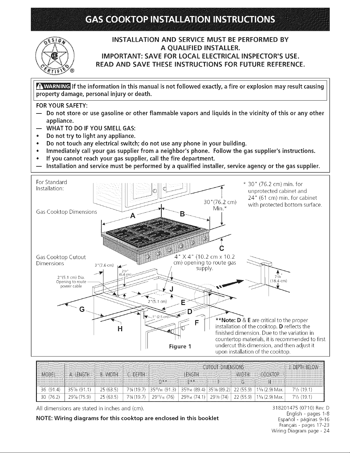
For Standard
Installation:
Gas Cooktop Dimensions
GasCooktop Cutout
Dimensions 3"(7.6cm)
2"(5.1 cm) Dia.
Opening to route
power cable
G
* 30" (76.2 cm) rain. for
unprotected cabinet and
24" (61 cm) rain. for cabinet
with protected bottom surface.
C
4" X 4" (10.2 cmx 10.2
cm) opening to route gas
supply.
71/4
(18.4 cm)
**Note: D & Eare critical to the proper
H
Figure 1
installation of the cooktop. D reflects the
finished dimension. Due to the variation in
countertop materials, it isrecommended to first
undercut this dimension, and then adjust it
upon installation of the cooktop.
36 (91.4) 357/8 (91.1) 25 (63.5) 73A(19.7) 35_s/_ (91.3) 353/_ (89.4) 35%(89.2) 22 (55.9) 1% (2.9) Max. 772 (19.1)
30 (76.2) 297/8(75.9) 25(63.5) 73A(19.7) 29_s/_6(76) 293/_ (74.1) 2978(74) 22(55.9) 1%(2.9) Max. 772 (19.1)
All dimensions are stated in inches and (cm).
NOTE: Wiring diagrams for this cooktop are enclosed in this booklet
318201475 (0710) Rev. D
English - pages 1-8
Espaflol - p_iginas 9-16
Frangais - pages 17-23
Wiring Diagram page - 24
Page 2
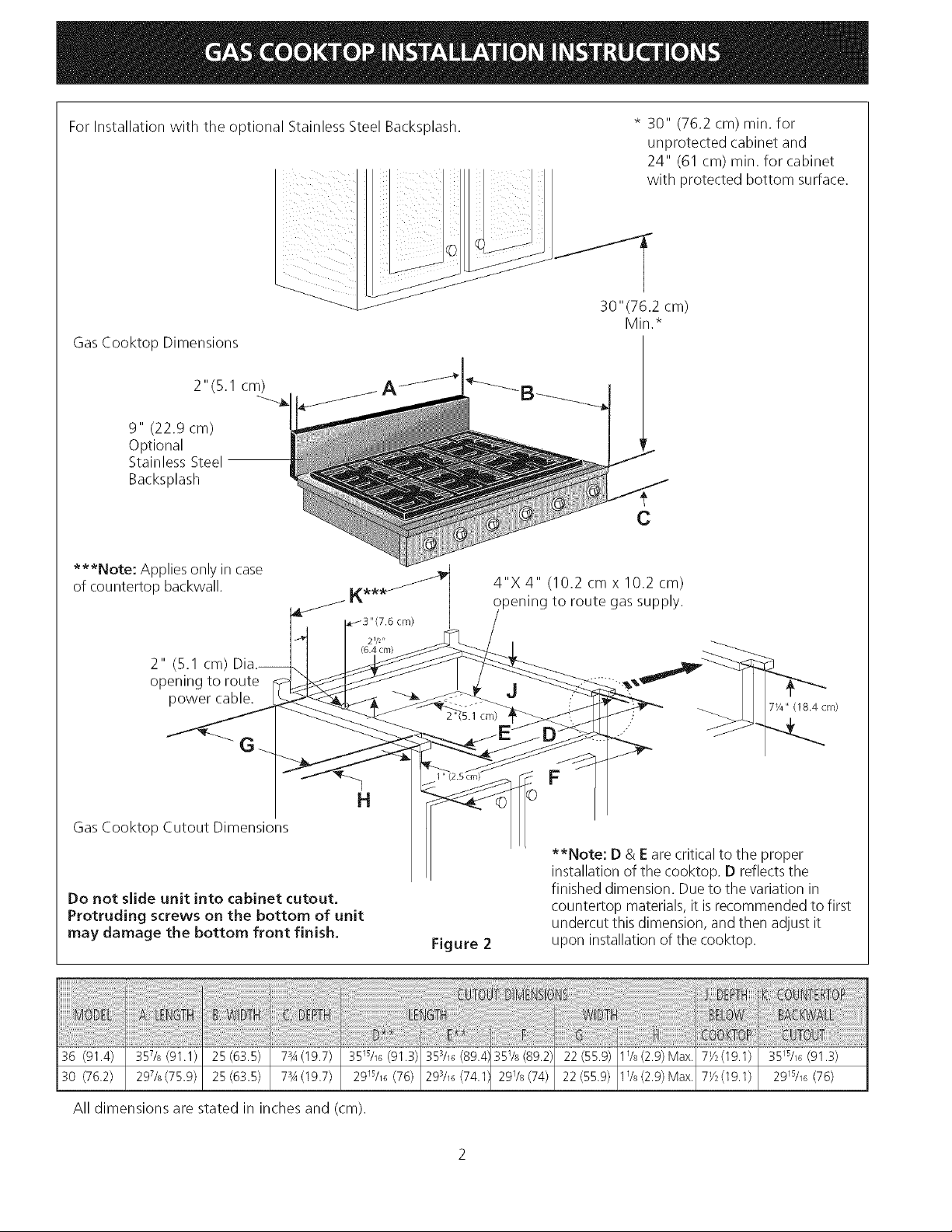
For Installation with the optional Stainless Steel Backsplash.
GasCooktop Dimensions
2" (5. I cm)
9" (22.9 cm)
Optional
Stainless Steel
Backsplash
* 30" (76.2 cm) min. for
unprotected cabinet and
24" (61 cm) min. for cabinet
with protected bottom surface.
C
***Note: Applies only in case
of countertop backwall.
21/2"
2" (5.1 cm)
opening to route
power cable.
4"X 4" (10.2 cm x 10.2 cm)
pening to route gas supply.
J
7Y4" (18.4 cm)
H
GasCooktop Cutout Dimensions
**Note: D & E are critical to the proper
installation of the cooktop. D reflectsthe
Do not slide unit into cabinet cutout.
Protruding screws on the bottom of unit
may damage the bottom front finish.
Figure 2
finished dimension. Due to the variation in
countertop materials, it isrecommended to first
undercut this dimension, and then adjust it
upon installation of the cooktop.
ii__i_!_!!__!!_!_______i__ii__i_iilli__i!_!i_ii_ii_!!_i!ii!iii!_!i_!ii!i_!ii_i_!_i_!!i!i!i!i¸iiii_i_!i_:i!_i_ii_ii_!i!ii_i_i__!ii!ii!ii!_i!_i_i!_!!ii!ii!!!!i_ii!ii!i_i_i_i_i_iiii_iii_i__ii!_!ii_iiiii_i_i_!i!i__!_!!!!__i_!!!_i__!__!____i_i__ii_i!_ii!!_!!i_i!_i!_i!_i!_i!_i!_iii_i!_i!_!!_!_!!_!!_!!_!!_!__i!___!i_!i_!i_!i_!i_!i_!i_!i__!i_ii_ii_ii_iii_iiiii_ii_ii!ii!ii!!iiiii!ii!i!!ii!i!ii!!i!i!i!ii!iiiiiii!!!!_i_i___i_i______!
i_i_';!il!i!ii_i'i:ii_;i:ilili!i__!i_i__i_iii!_iii!i!!_i,_i!i!i!i!_ii_ii!i!i!ili!!!i_i!_i_i_ii!_ii_!!i_i!i!i_i_i_i_!_i___i_i_i!__ii_Ii_i!_!__ii_ii_i_i_iIi,!iil!ii_!_i_!i_i!iii'ili_i'iiilliii_i!i_!,!__il_ii_ili!i_i_i_iii__i_!!ii!i_!i!i!i!_i!i!,iii!iii!i!i!_:i'il!_!ii_i_iiii!ii_:i!_ii_ii_fi'ili'ililiiilililil!i_!_!i_!i_!ii_ii_ii_iii_!ii_f__il_i_i_i_il!,_!i!i_i_i_i_i_!_:!_ii:i_ii:i_!_i_i_iii'i'i'i_ii'i_!iiiiiliiii_iiiij_i_i_i_i!_iiii_ii_ii_ii_ii_ii_i_iii_!__ii_;ii_ilii_i!_i!i_!iiiii!_i_i_i_iii_Iililii_i_i_i_i_!_i!ili__iij_i!!i_ili!_!il_iiii!i!_i!_i_i,il!ii!!ii_iil_!_IS!Ifi!!iii!_!:ii_iiii_ilii_i_i_i_i_i_i_ii_i!_!i!i_!_i_i_!_i_!_!_!_!_!!_i!i!_!!_i!_ill!_!_!_i!_ii_i!!i_ii_ii_iiiiii!i!i!i!i!i!i!iiiiiliiliii!!ii!_i_i_i_!_i_iji!i_ii_i_!!_ii!iiiil_i_!!_!_i_!_ii_ii_iiil_!i!!i!!_ii_ii_iiii_i_!_!ii!_!_!_i!!__!_!___!__,!!!_!_!__i_'i'!_!_!_!_!_!!i__!i_i_ii_!i_ii!i!i_i_i_i_i_!_!!!!!!!!!!!!!!illiliiil_!!!__i!_i_!'i'i'i_i_!_iii_il_i!_!i_i!iili!if_!_iilliiii_!__!i_ii_ii_i__!__i_!_'i_i:_ii_!,_ii!ii'ili_!i_,i!ii_!iiiii_i_i_ii_i_i_ili_ii!_i_!_!ii_!ii_i__!
36 (91.4) 35%(91.1) 25(63.5) 7_A(19.7) 35_s/_6(91.3) 35_A_(89.4 35_/_(89.2) 22(55.9) l_/_ (2.9) Max. 7Y_(19.1) 35_sA_(91.3)
30 (76.2) 29%(75.9) 25(63.5) 7_A(19.7) 29_s/_ (76) 29_/_ (74.1 29_/s(74) 22(55.9) 1%(2.9)Max. 7Y_(19.1) 29_s/_6(76)
All dimensions are stated in inches and (cm).
Page 3
Important Notes to the Installer
1. Readallinstructionscontainedintheseinstallation
instructionsbeforeinstallingthecooktop.
2. Removeallpackingmaterialbeforeconnectingthe
electricalsupplytothecooktop.
3. Observeallgoverningcodesandordinances.
4. Besuretoleavetheseinstructionswiththeconsumer.
5. Note:Foroperationat2000ft.elevationsabovesee
level,applianceratingshallbereducedby4percent
foreachadditional1000ft.
Important Note to the Consumer
Keep these instructions with your Use and Care Guide for
future reference.
Depth Adjustment Filler Kit
This cooktop isdesigned to replace existing unit. If the
depth of your countertop opening isbigger than 7Y4" (18.4
cm) and lessthan 8Y2" (21.6 cm) you can order a free filler
kit by calling ServiceCenter at 1-877-4ELECTROLUX(1-
877-435-3287).
For36" model: #903051-9010
For30" model: #903051-9100
Optional Items Available:
• A 9" (22.9 cm) Stainless Steel Backsplash Kit
#903048-9010 for 36" model or #903048-9100 for 30"
model.
A Black Knobs Kit #903049-9120 for 36" model or
#903049-9110 for 30" model.
Those kits can be order through the Service Center at
1-877-4ELECTROLUX(1-877-435-3287). However all cost
related to those kits will be at customer charges.
IMPORTANT SAFETY
INSTRUCTIONS
Installation of this cooktop must conform with local codes
or, in the absence of local codes, with the National Fuel
Gas Code ANSI Z223.1/NFPA54--1atest edition in the
United States, or in Canada, with the Canadian Fuel Gas
Code, CAN/CGA B149 and CAN/CGA B149.2.
This cooktop has been design certified by CSA
International. As with any appliance using gas and
generating heat, there are certain safety precautions you
should follow. You will find them in the Use and Care
Guide, read it carefully.
• Be sure your cooktop is installed and grounded
properly by a qualified installer or service
technician.
This cooktop must be electrically grounded in
accordance with local codes or, in their absence,
with the National Electrical Code ANSI/NFPA No.
70--latest edition in the United States, or in
Canada, with the Canadian Electrical Code, CSA
C22.1 Part 1.
• The burners can be lit manually during an
electrical power outage. To light a burner, hold a
lit match to the burner head, then slowly turn the
Surface Control knob to MTE. Use caution when
lighting burners manually.
• Do not store items of interest to children in
cabinets above the cooktop. Children could be
seriously burned climbing on the cooktop to reach
items.
• To eliminate the need to reach over the surface
burners, cabinet storage space above the burners
should be avoided.
• Adjust surface burner flame size so it does not
extend beyond the edge of the cooking utensil.
Excessive flame is hazardous.
• Never use your cooktop for warming or heating
the room, Prolonged use of the cooktop without
adequate ventilation can be hazardous.
• Do not store or use gasoline or other flammable
vapors and liquids near this or any other
appJiance. Explosions or fires could result.
The electrical power to the cooktop
must be shut off while gas line connections are
being made. FaiJure to do so couJd resuJt in serious
injury or death.
When installed in a manufactured (mobile) home
installation must conform with the Manufactured Home
Construction and Safety Standard, title 24 CFR,part
3280 [Formerly the Federal Standard for Mobile Home
Construction and Safety, title 24, HUD (part 280)] or,
when such standard is not applicable, the Standard for
Manufactured Home Installation, ANSI/NCSBCS A225. I
or with local codes where applicable.
Page 4
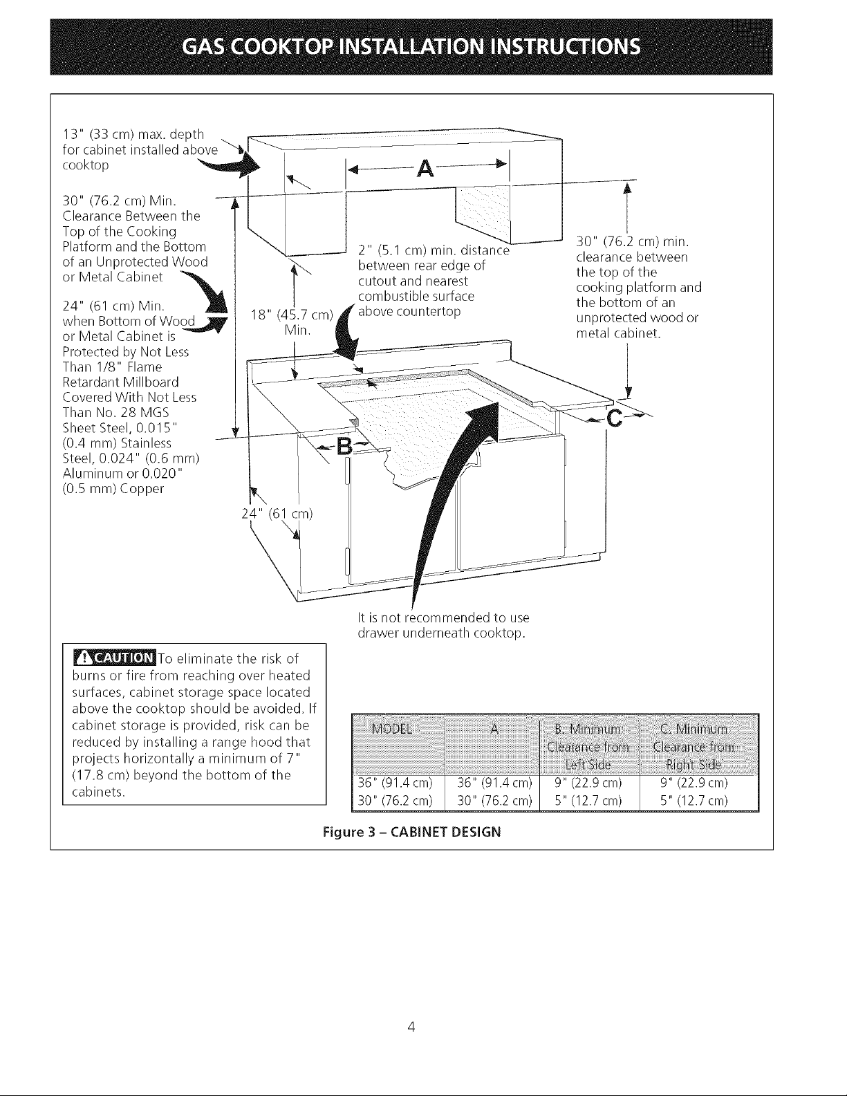
13"(33cm)max.depth ,
forcabinetinstalledabove
cooktop
30"(76.2cm)Min.
ClearanceBetweenthe
TopoftheCooking
PlatformandtheBottom
ofanUnprotectedWood
orMetalCabinet
24"(61cm)Min.
whenBottomofWoodjlf
orMetalCabinetis
ProtectedbyNotLess
ThanI/8" Flame
RetardantMillboard
Covered With Not Less
Than No. 28 MGS
Sheet Steel, 0.015"
(0.4 mm) Stainless
Steel, 0.024" (0.6 mm)
Aluminum or 0.020"
(0.5 mm) Copper
"_-. _min
"l_ between rear edge of
18" (45.7 cm) P
Min.
cutout and nearest
combustible surface
30" (76.2 cm) min.
clearance between
the top of the
cooking platform and
the bottom of an
unprotected wood or
metal cabinet.
_To eliminate the risk of
burns or fire from reaching over heated
surfaces, cabinet storage space located
above the cooktop should be avoided. If
cabinet storage is provided, risk can be
reduced by installing a range hood that
projects horizontally a minimum of 7"
(17.8 cm) beyond the bottom of the
cabinets.
It isnot recommended to use
drawer underneath cooktop.
36" (91.4cm) 36" (91.4 cm) 9" (22.9 cm) 9" (22.9 cm)
30" (76.2cm) 30" (76.2 cm) 5" (12.7 cm) 5" (12.7 cm)
Figure 3 - CABINET DESIGN
Page 5
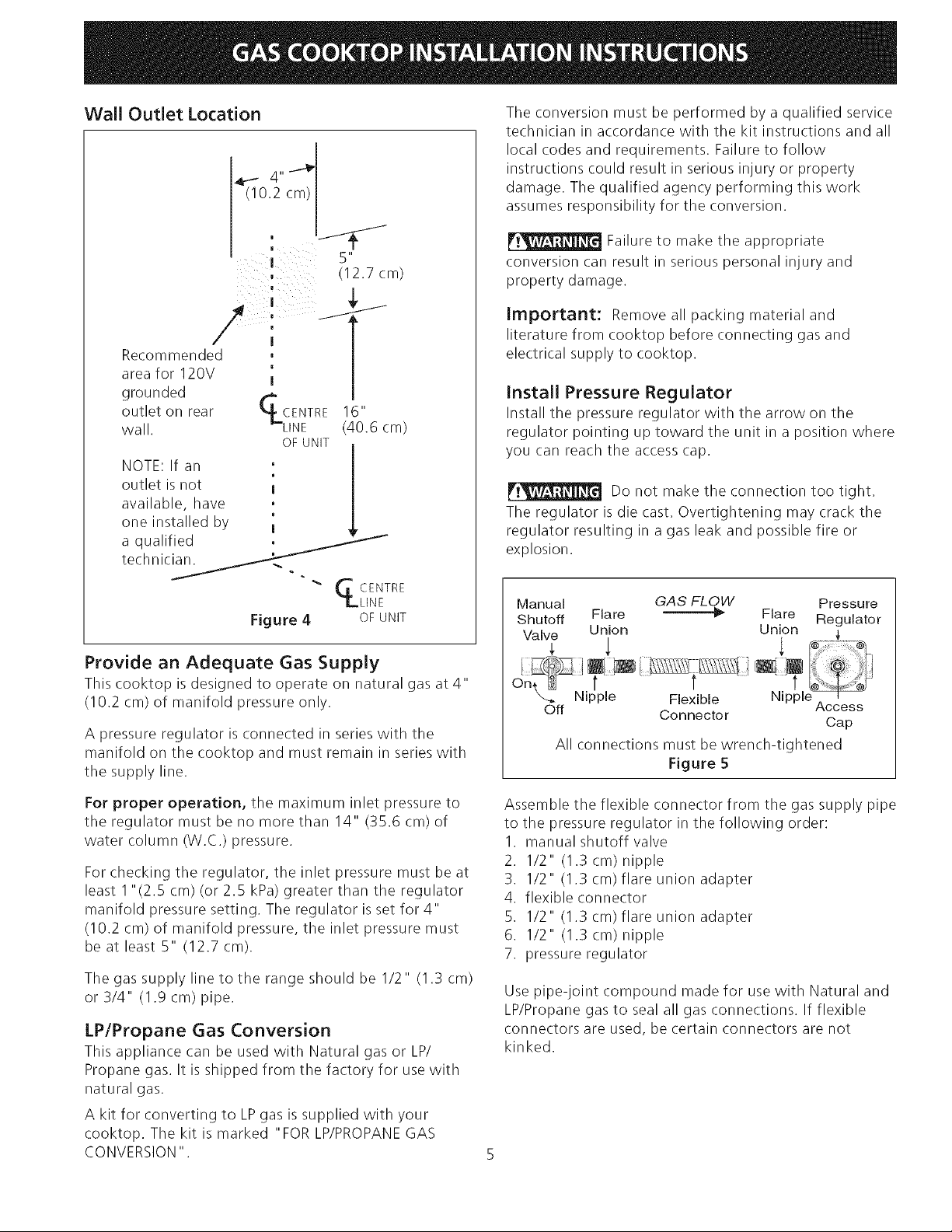
Wall Outlet Location
_ 4,,-_
(10.2 cm)
Recommended , I
area for 120V '1 |
grounded r,_ |
outlet on rear _4 CENTRE 16
wall. _LINE (40.6 cm)
OF UNIT
NOTE: If an
outlet is not I
available, have
0
one installed by I
a qualified :
technicS.
Figure 4 OFUNIT
(12.7 cm)
ii
GCENTR E
LLINE
The conversion must be performed by a qualified service
technician in accordance with the kit instructions and all
local codes and requirements. Failure to follow
instructions could result in serious injury or property
damage. The qualified agency performing this work
assumes responsibility for the conversion.
Failure to make the appropriate
conversion can result in serious personal injury and
property damage.
Important: Remove all packing material and
literature from cooktop before connecting gas and
electrical supply to cooktop.
Install Pressure Regulator
Install the pressure regulator with the arrow on the
regulator pointing up toward the unit in a position where
you can reach the access cap.
Do not make the connection too tight.
The regulator is die cast. Overtightening may crack the
regulator resulting in a gas leak and possible fire or
explosion.
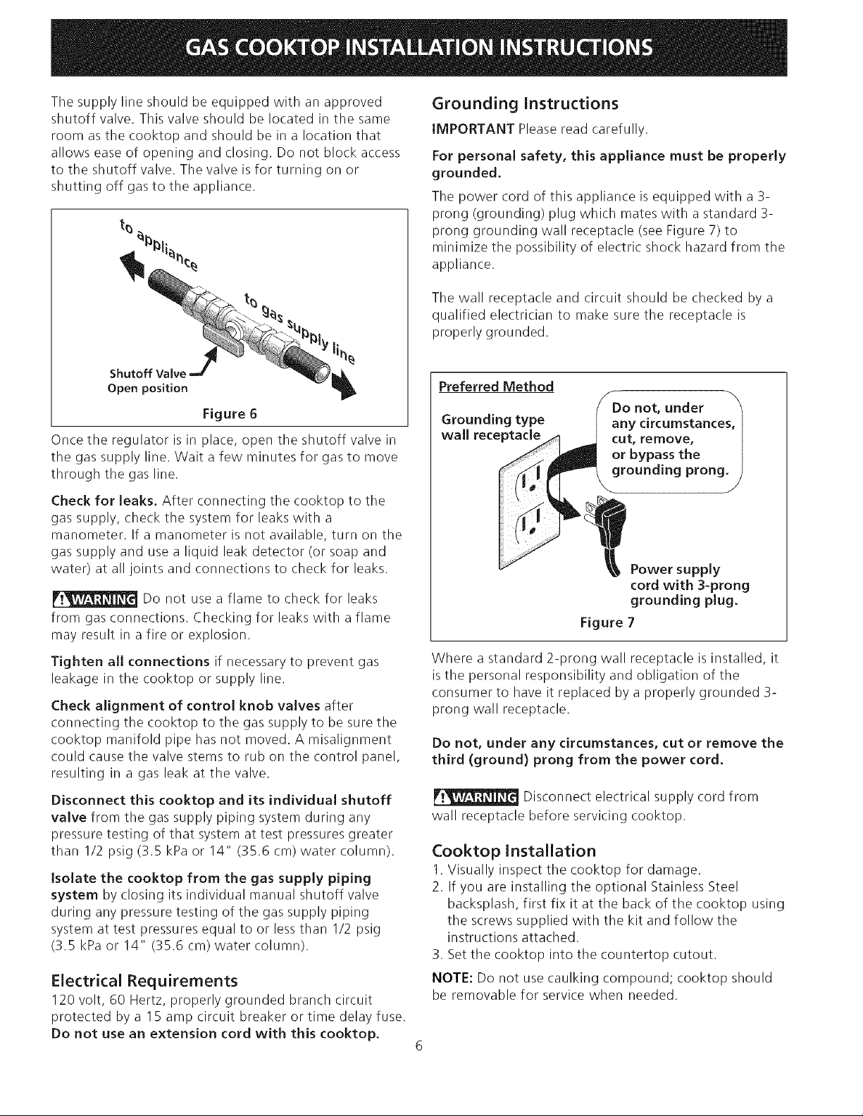
Manual GAS FLOW Pressure
Shutoff Flare _" Flare Regulator
Valve Union Union
Provide an Adequate Gas Supply
This cooktop is designed to operate on natural gas at 4"
(10.2 cm) of manifold pressure only.
A pressure regulator is connected in series with the
manifold on the cooktop and must remain in series with
the supply line.
For proper operation, the maximum inlet pressure to
the regulator must be no more than 14" (35.6 cm) of
water column (W.C.) pressure.
For checking the regulator, the inlet pressure must be at
least I "(2.5 cm) (or 2.5 kPa) greater than the regulator
manifold pressure setting. The regulator isset for 4"
(10.2 cm) of manifold pressure, the inlet pressure must
be at least 5" (12.7 cm).
The gas supply line to the range should be 1/2" (1.3 cm)
or 3/4" (1.9 cm) pipe,
LP/Propane Gas Conversion
This appliance can be used with Natural gas or LP/
Propane gas. It is shipped from the factory for use with
natural gas.
A kit for converting to LPgas is supplied with your
cooktop. The kit is marked "FOR LP/PROPANEGAS
CONVERSION".
Nipple Flexible
Off Connector
Access
Cap
All connections must be wrench-tightened
Figure 5
Assemble the flexible connector from the gas supply pipe
to the pressure regulator in the following order:
1. manual shutoff valve
2. I/2" (1.3 cm) nipple
3. I/2" (1.3 cm) flare union adapter
4. flexible connector
5. I/2" (1.3 cm) flare union adapter
6. I/2" (1.3 cm) nipple
7. pressure regulator
Use pipe-joint compound made for use with Natural and
LP/Propane gas to seal all gas connections. If flexible
connectors are used, be certain connectors are not
kinked.
Page 6
Thesupplylineshouldbeequippedwithanapproved
shutoffvalve.Thisvalveshouldbelocatedinthesame
roomasthecooktopandshouldbeina locationthat
allowseaseofopeningandclosing.Donotblockaccess
totheshutoffvalve.Thevalveisforturningonor
shuttingoffgasto theappliance.
Grounding Instructions
iMPORTANT Please read carefully.
For personal safety, this appliance must be properly
grounded.
The power cord of this appliance is equipped with a 3-
prong (grounding) plug which mates with a standard 3-
prong grounding wall receptacle (see Figure 7) to
minimize the possibility of electric shock hazard from the
appliance.
The wall receptacle and circuit should be checked by a
qualified electrician to make sure the receptacle is
properly grounded.
Shutoff Valve
Open position
Figure 6
Once the regulator is in place, open the shutoff valve in
the gas supply line. Wait a few minutes for gas to move
through the gas line.
Check for leaks. After connecting the cooktop to the
gas supply, check the system for leaks with a
manometer. If a manometer is not available, turn on the
gas supply and use a liquid leak detector (or soap and
water) at all joints and connections to check for leaks.
Do not use a flame to check for leaks
from gas connections. Checking for leaks with a flame
may result in afire or explosion.
Tighten all connections if necessary to prevent gas
leakage in the cooktop or supply line.
Check alignment of control knob valves after
connecting the cooktop to the gas supply to be sure the
cooktop manifold pipe has not moved. A misalignment
could cause the valve stems to rub on the control panel,
resulting in a gas leak at the valve.
Disconnect this cooktop and its individual shutoff
valve from the gas supply piping system during any
pressure testing of that system at test pressures greater
than 1/2 psig (3.5 kPa or 14" (35.6 cm) water column).
Isolate the cooktop from the gas supply piping
system by closing its individual manual shutoff valve
during any pressure testing of the gas supply piping
system at test pressures equal to or lessthan 1/2 psig
(3.5 kPa or 14" (35.6 cm) water column).
Electrical Requirements
120 volt, 60 Hertz, properly grounded branch circuit
protected by a 15 amp circuit breaker or time delay fuse.
Do not use an extension cord with this cooktop.
Preferred Method
Grounding type
wall receptacle
Where a standard 2-prong wall receptacle is installed, it
isthe personal responsibility and obligation of the
consumer to have it replaced by a properly grounded 3-
prong wall receptacle.
Do not, under any circumstances, cut or remove the
third (ground) prong from the power cord.
Disconnect electrical supply cord from
wall receptacle before servicing cooktop.
Do not, under
any circumstances
cut, remove,
or bypass the
grounding prong.
Power supply
cord with 3-prong
grounding plug.
Figure 7
Cooktop Installation
1. Visually inspect the cooktop for damage.
2. If you are installing the optional Stainless Steel
backsplash, first fix it at the back of the cooktop using
the screws supplied with the kit and follow the
instructions attached.
3. Set the cooktop into the countertop cutout.
NOTE: Do not use caulking compound; cooktop should
be removable for service when needed.
Page 7
Check Operation
Refer to the Use and Care Guide packaged with the
cooktop for operating instructions and for care and
cleaning of your cooktop.
Do not touch the burners. They may be
hot enough to cause burns.
1. Burner Bases and Burner Caps
This range is equipped with sealed burners asshown
(Figure 8). All pieces are at their place. Take note where
they are. Remove all packaging material located
under the Dual Surface burner head. Make sure the
burner is properly aligned and leveled.
NOTE: There are no burner adjustments necessary on
this range.
30" Modem
Burner Cap
Burner Base
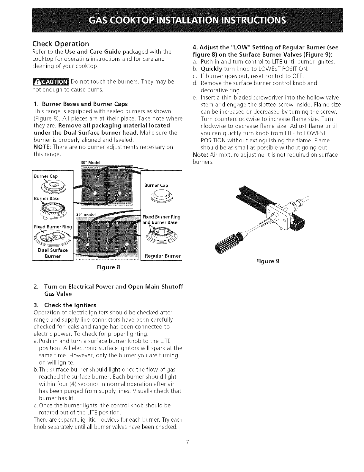
4. Adjust the "LOW" Setting of Regular Burner (see
figure 8) on the Surface Burner Valves (Figure 9):
a. Push in and turn control to LITEuntil burner ignites.
b. Quickly turn knob to LOWEST POSITION.
c. If burner goes out, reset control to OFF.
d. Remove the surface burner control knob and
decorative ring.
e. Insert a thin-bladed screwdriver into the hollow valve
stem and engage the slotted screw inside. Flame size
can be increased or decreased by turning the screw.
Turn counterclockwise to increase flame size. Turn
clockwise to decrease flame size. Adjust flame until
you can quickly turn knob from LITEto LOWEST
POSITIONwithout extinguishing the flame. Flame
should be as small as possible without going out.
Note: Air mixture adjustment isnot required on surface
burners.
36" model
Dual Surface
Burner
Fixed Burner Ring
and Burner Base
Regular Burner
Figure 8
2. Turn on Electrical Power and Open Main Shutoff
Gas Valve
3. Check the Igniters
Operation of electric igniters should be checked after
range and supply line connectors have been carefully
checked for leaks and range has been connected to
electric power. To check for proper lighting:
a.Push in and turn asurface burner knob to the LITE
position. All electronic surface ignitors will spark at the
same time. However, only the burner you are turning
on will ignite.
b.The surface burner should light once the flow of gas
reached the surface burner. Each burner should light
within four (4) seconds in normal operation after air
has been purged from supply lines. Visually check that
burner has lit.
c.Once the burner lights, the control knob should be
rotated out of the LITEposition.
There are separate ignition devices for each burner. Try each
knob separately until all burner valves have been checked.
Figure 9
Page 8
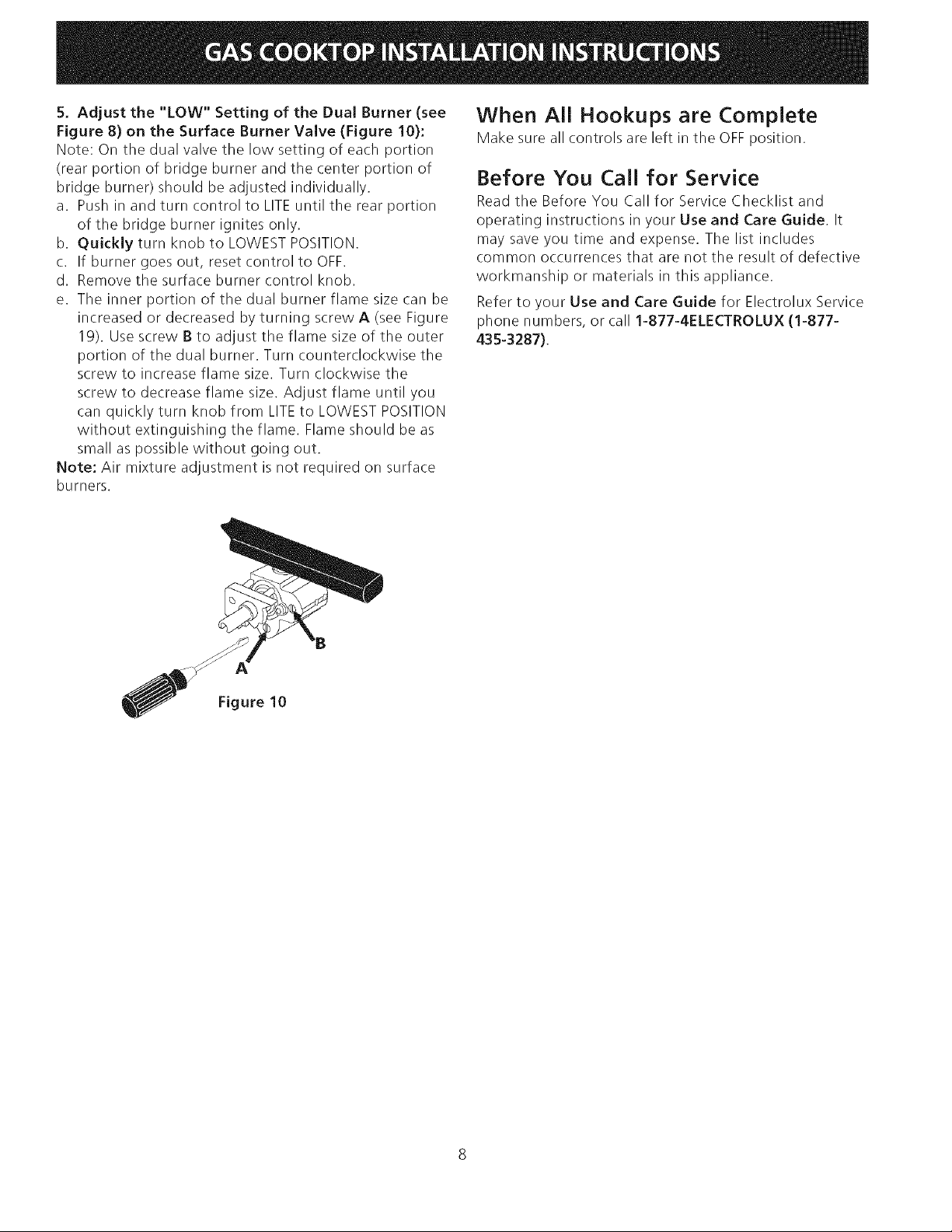
5. Adjustthe "LOW"Settingof theDualBurner(see
Figure 8) on the Surface Burner Valve (Figure 10):
Note: On the dual valve the low setting of each portion
(rear portion of bridge burner and the center portion of
bridge burner) should be adjusted individually.
a. Push in and turn control to LITEuntil the rear portion
of the bridge burner ignites only.
b. Quickly turn knob to LOWEST POSITION.
c. If burner goes out, reset control to OFF.
d. Remove the surface burner control knob.
e. The inner portion of the dual burner flame size can be
increased or decreased by turning screw A (see Figure
19). Use screw B to adjust the flame size of the outer
portion of the dual burner. Turn counterclockwise the
screw to increase flame size. Turn clockwise the
screw to decrease flame size. Adjust flame until you
can quickly turn knob from LITEto LOWEST POSITION
without extinguishing the flame. Flame should be as
small as possible without going out.
Note: Air mixture adjustment isnot required on surface
burners.
When All Hookups are Complete
Make sure all controls are left in the OFF position.
Before You Call for Service
Read the Before You Call for Service Checklist and
operating instructions in your Use and Care Guide, It
may save you time and expense. The list includes
common occurrences that are not the result of defective
workmanship or materials in this appliance.
Refer to your Use and Care Guide for Electrolux Service
phone numbers, or call 1-877-4ELECTROLUX (1-877-
435-3287).
Figure 10
Page 9

LA INSTALACiON Y EL SERVICIO DEBEN SER REALIZADOS
POR UN INSTALADOR CAUFICADO.
IMPORTANTE: GUARDE ESTAS INSTRUCCIONES PARA USO DEL
iNSPECTOR EUeCTRICO LOCAL.
LEA Y GUARDE ESTAS INSTRUCCIONES PARA FUTURAS REFERENCIAS
F_ Si todas las instrucciones de _ste manual no son observadas a la letra, sepuede ocurrir incendios o
explosiones que pueden causar da5os materiales, lesiones o la muerte.
PARA SU SEGURIDAD:
-- No almacene o utilice gasolina u otros vapores y liquidos inflamables cerca de _ste o cualquier otro artefacto.
-- QUE HACERSIHAY FUGAS DEGAS/E
• No intente de encender ningun artefacto
• No toque ningun interruptor el_ctrico; no utilice ningun aparato t_l_fonico en su edificio.
• Llame inmediatamente el abastecedor de gas desde el tel_fono de un vecino. Siga las instruccionesdel abastecedor de gas.
• Encaso que no puede contactar el abastecedor de gas Ilarne al departamento de bomberos.
-- La instalaciOn y el servicio t_l_fonico deben set realizados pot un instalador calificado, por un servicio tecnico certificado o
pot el abastecedor de gas.
Para la Instalacion
Est_indar:
Dimensiones de la
aarrilla de cocinar a
gas
3" (7.6 cm)
Abertura de 2" (5.1 cm)
de diametro para hacer
)asar el cable de
alimentacion.
Dimensiones del
para la parrilla de
cocinar a gas H
* 30" (76.2 cm) min para un armario
protegido.
24" (61 cm) min para una superficie no
30" (76.2 cm)
Min.*
C
_,bertura de 4" X 4" (10.2cm x
10.2cm) para el suministro de gas.
**Nota: "D & E" son criticos para la instalacion
adecuada de la cocina. Pot favor, aseg0rese de
respetar estas dimensiones. "D" refleja una
dimension terminada que se recomienda para
socavar esta dimension y ajustar en el momento de
la instalacion del aparato debido a la variacion de
Figura 1
los materiales de la cocina.
7¼" (18.4 cm)
36 (91.4) 357/8 (91.1) 25 (63.5)
30 (76.2) 297/8(75.9) 25(63.5)
73A(19.7) 35W_(91.3) 35%e(89.4) 351/8(89.2) 22(55.9) 1Vs(2.9)Max.
73A(19.7) 29W_(76) 293/_(74.1) 29V8(74) 22(55.9) 1Vs(2.9)Max.
Todas las dimensiones se dan en pulgadas (cm).
La dimension Fincluye un espacio de 5" por debajo de la plancha de
cocinar para la conexiOn de la linea de suministro de gas.
NOTA: Se adjunta los diagramas de cables de esta plancha de
cocinar con el libreta.
318201475 (0710) Rev. D
English - pages 1-8
Espanol - p_iginas 9-16
Fran_ais - pages 17-23
Diagrama de la instalaciOn akimbrica p_qgina - 24
Page 10

Para ver la InstalaciOn con el Panel Protector Opcional de
Acero Inoxidable.
Dimensiones de la parrilla
de cocinar a gas
2" (5.I cm)
Panel Protector Optional
de Acero Inoxidable de --
9" (22,9 cm)
***Nota: Se aplica s01o en
caso de Panel Protector.
* 30" (76.2 cm) rain para un armario protegido.
24" (61 cm) rain para una superficie no protegida.
C
Abertura de 4" X 4" para el
suministro de gas.
Abertura de 2" (5.1cm)
de diametro para
pasar el cable de
alimentaciOn.
7¼" (18.4 cm)
Dimensiones del hueco
para la parrilla de
cocinar a gas
No deslizar dentro del hueco de la alacena.
Los tornillos que sobresalen de la parte
inferior de la unidad pueden daEar el
acabado inferior del frente.
/_1 4/135% (91.1) 25 (63.5) 73A(19.7) 35_s/_ (91.3) 353/_6(89.4) 35% (89.2) 22 (55.9) l_/_(2.9)Max. 7V2(19.1) 35_s/_6(91.3)
//_J/129% (75.9) 25(63.5) 73A(19.7) 29_s/_6(76) 293/_6 (74.1) 29% (74) 22(55.9) Y/8(2.9)Max. 7V2(19.1) 29_s/_6(76)
H
I " (2.5 cm) F
Figura 2
**Nota: "D & E" son criticos para la instalaci6n adecuada
de la cocina. Por favor, aseg0rese de respetar estas
dimensiones. "D" refleja una dimensi6n terminada que
se recomienda para socavar esta dimensi6n y ajustar en el
momento de la instalaci6n del aparato debido a la
variaci6n de los materiales de la cocina.
Todas las dimensiones se dan en pulgadas (cm).
10
Page 11

Notas importantes para el instalador:
I. Leatodaslasinstruccionesdeinstalaci6nantesde
realizarlainstalaciOndelaplanchadecocinar.
2.Retiretodoslosarticulosdeembalajeantesderealizar
lasconexionesel_ctricasalaplanchadecocinar.
3.ObservetodosloscOdigoso reglamentosestatales
4.Aseg0resequeelconsumidortengaestasinstrucciones.
5.NOTA:ParalautilizaciOnamasde2000piesdealtura,
lapotenciadelaparatodeberaserreducidade4por
cientoacadaI 000piesadicionales.
Notas importantes para el consumidor
Guarde todas lasinstrucciones con su manual del usuario
para futuras referiencias.
Juego de Relleno para Ajuste de
Profundidad
Estacocina ha sido diseflada para reemplazar la unidad
existente. Si la profundidad de la abertura de su cocina es
mayor que 7¼" (18,4 cm.) y menor que 8Y2" (21,6 cm.),
puede ordenar un juego de relleno gratuito Ilamando al
Centro de Servicio al Cliente al 1-877-4ELECTROLUX
(1-877-435-3287),
Paramodelo 36" : #903051-9010
Paramodelo 30" : #903051-9100
Accesorios Opcionales Disponibles:
* Juego de Panel Protector Opcional de Acero Inoxidable
de 9" (22,9 cm) #903048-9010 para modelo 36" o
#903048-9100 para modelo 30".
o Juego de Perillas Negras #903049-9120 para modelo 36"
o #903049-9110 para modelo 30".
Se puede ordenar a trav6s del Centro de Servicios,
Ilamando al 1-877-4ELECTROLUX(1-877-435-3287),
Todos los costos relacionados con estos juegos sefacturaran
al cliente.
INSTRUCCIONES DE
SEGURIDAD IMPORTANTES
La instalaciOn de esta plancha de cocinar debe realizarse
en conformidad con los cOdigos locales o, si estos no
existen, con el National Fuel Gas Code ANSI Z223.1/
NFPA54 - 01tima ediciOn en los Estados Unidos, o en
Canada, con el Canadian Fuel Gas Code, CAN/CGA B149
y CAN/CGA B149.2.
* La instalaciOn de aparatos diseflados para instalaciOn
en casas prefabricadas (m6viles) debe conformar con el
Maufactured Home Consturction and Safet Standard,
titulo 24CFR, parte 3280 [Anteriormente el Federal
Standard for Mobil Home Construction and Safety,
titulo 24, HUD (parte 280)] o cuando tal estandar no se
aplica, el Standard fo Manufactured Home Installation,
ANSI/NCSBCS 225.1, o con los c6digos locales.
El diseho de esta plancha de cocinar cuenta con la
aprobaci6n del CSA international. AI igual que todos los
artefactos a gas que generan calor, deben seguirse ciertas
medidas de seguridad. Vienen con el Manual del Usuario.
Lea atentamente el manual.
* Aseg_rese que la plancha de cocinar sea instalada
y puesta a tierra correctamente pot un instalador
o t_cnico calificado.
* La plancha de cocinar debe conectarse
eJ_ctricamente a tierra de acuerdo con los c6digos
Jocales o, de no existir, con el cbdigo eJ_ctrico
ANSI/NFPA No. 70 - eltima edici6n en los Estados
Unidos, or in Canada, con el Canadian Electrical
Code, CSA C22.1 Parte 1.
* Los quemadores pueden encenderse manualmente
durante una interrupci6n del suministro el_ctrico.
Para encender un quemador, mantenga un fbsforo
encendido en el extremo del quemador, luego
gire suavemente Ja perilla hasta LITE (encendido).
Tenga cuidado al encender los quemadores en
forma manual.
* No deje articulos que interesan los ni_os en los
armarios que est_n sobre la la plancha de codnar.
Les podria causar quemaduras graves si intentan
subirse para alcanzarlos,
* Para eJiminar el riesgo de extender pot encima de
los quemadores superiores, deberia evitar el
espacio de almacenamiento del armario,
Iocalizado pot encima de estos quemadores
* Gradue el tama_o de la llama de modo que no
sobrepase eJ borde del utensiJio de cocina.
Demasiada llama es peligrosa.
* No utilice jam_s la cocina como calefactor, El uso
prolongado de la cocina sin la ventilaciOn adecuada
puede ser peligroso,
* Mantenga el _rea cerca de este artefacto o de
cualquier otto artefacto despejada de sustandas
combustibles, gasolina y otros liquidos
inflamables. Se puede ocurrir incendios o
explosiones.
El suministro el_ctrico a la plancha
de codnar debe de set cerrado durante las
conexiones a la linea. De Io contrario se puede
resultar lesiones graves o la muerte.
11
Page 12
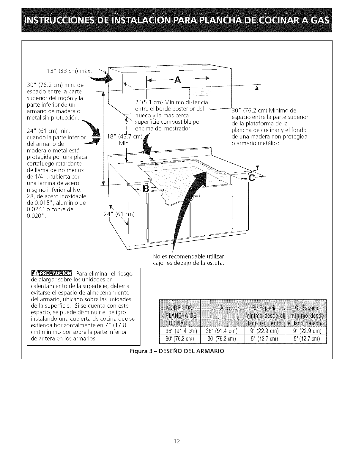
13"(33cm)max.
30"(76.2cm)rain.de
espacioentrelaparte -
superiordelfog6nyla
parteinferiordeun
armariodemaderao
metalsinprotecci6n.
_ 7 l
_30 " (76 m)IMinimo de
24"(61cm)rain. _j_
cuandolaparteinferior
delarmariode
18,, (45_'_7c!!_ _r_r_cicee_0rmllO_tst_bOIe p0r _Pi:ii_i_ar1./_iiiii_iltYli_i i i_ r
Min. o armario metalico.
maderao metalesta
protegidaporunaplata
cortafuegoretardante
dellamadenomenos
de1/4",cubiertacon
unalaminadeacero
msgnoinferioralNo.
28,deaceroinoxidable
de0.015",aluminiode
0.024"ocobrede
0.020".
V!_ Para eliminar el riesgo
de alargar sobre los unidades en
calentamiento de la superficie, deberia
evitarse el espacio de almacenamiento
del armario, ubicado sobre lasunidades
delasuperficie. Sisecuentacon este
espacio, se puede disminuir el peligro
instalando una cubierta de cocina que se
extienda horizontalmente en 7" (17.8
cm) minimo por sobre la parte inferior
delantera en los armarios.
No es recomendable utilizar
cajones debajo de la estufa.
36" (91.4 cm) 36" (91.4 cm) 9" (22.9 cm) 9" (22.9 cm)
30"(76.2cm) 30"(76.2cm) 5" (12.7cm) 5"(12.7cm)
Figura 3 - DESEBIO DEL ARMARIO
12
Page 13
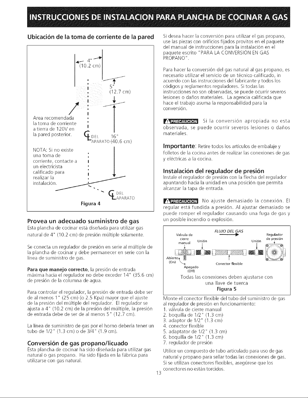
Ubicadon de la toma de corriente de la pared
|
(12.7 cm)
T
Si desea hacer la conversi6n para utilizar el gas propano,
use laspiezas con orificios fijados provitos en el paquete
del manual de instrucciones para la instalaci6n en el
paquete escrito "PARA LA CONVERSIONEN GAS
PROPANO".
Para hacer la conversi6n del gas natural al gas propano, es
necesario utilizar el servicio de un t@cnicocalificado, in
acuerdo con lasinstrucciones del fabricante y todos los
c6digos y reglamentos reguladores. Si todas las
instrucciones no son observadas, se puede ocurrir severos
lesiones o dahos materiales. La agencia calificada que
hace el trabajo asuma la responsabilidad para la
conversi6n.
Area recomendada , |
la toma de corriente I |
a tierra de 120V en |
la pared posterior. _DEL
_"APARATO (40.6 cm)
NOTA: Si no existe
una toma de
corriente, contacte a I
un electricista
calificado para I
instalacidn
realizar la _
Figura 4
16"
_' GDEL
LAPARATO
Provea un adecuado suministro de gas
Estaplancha de cocinar esta disehada para utilizar gas
natural de 4" (10.2 cm) de presi6n m01tiple solamente.
Se conecta un regulador de presi6n en serie al m01tiple de
la plancha de cocinar y debe permanecer en serie con la
linea de suministro de gas.
Para que manejo correcto, la presi6n de entrada
maxima hacia el regulador no debe exceder 14" (35.6 cm)
de presi6n de la columna de agua.
Paracontrolar el regulador, la presi6n de entrada debe ser
de al menos 1" (25 cm) (o 2.5 Kpa) mayor que el ajuste
delapresi6ndelmOltipledelregulador. EIreguladorse
ajusta a 4" (10.2 cm) de la presi6n del mOltiple, la presi6n
de entrada debe de ser de al menos 5" (12.7 cm).
La linea de suministro de gas por el homo deberia tener un
tubo de 1/2" (1.3 cm) o de 3/4" (1.9 cm).
Conversi6n de gas propano/licuado
Esta plancha de cocinar ha sido disehada para utilizar gas
naturalogaspropano. Hasidofijadaenlafabricapara
utilizarse con gas natural.
F!_I_J_ Si la conversi6n apropiada no esta
observada, se puede ocurrir severos lesiones o daflos
materiales.
Importante: Retire todos los articulos de embalaje y
folletos de lacocina antes de realizar las conexiones de gas
y el_ctricas a la cocina.
Instaladon del regulador de presi6n
Instale el regulador de presiOn con la flecha del regulador
apuntando hacia la unidad en una posici6n que permita
alcanzar la tapa de entrada.
r.t_l__ No ajuste demasiado la conexi6n. El
regular esta fundida a presi6n. AI ajustar demasiado se
puede romper el regulador causando una fuga de gas y
un posible incendio o explosi6n.
Valvula de _1_ Regulador
cierre de p:esi6n
manual Uni6n Union
FLUJO DEL GAS
di
Apagado
(Off)
Todas las conexiones deben ajustarse con
Monte el conector flexible del tubo del suministro de gas
al regulador de presiOn en funcionamiento:
I. valvula de cierre manual
2. boquilla de 1/2" (1.3 cm)
3. adaptor de 1/2" (1.3 cm)
4. conector flexible
5. adaptator de 1/2" (1.3 cm)
6. boquilla de 1/2" (1.3 cm)
7. regulador de presiOn
Utilice un compuesto de tubo articulado para uso de gas
natural y propano para sellar todas las conexiones de gas.
Si se utilizan conectores flexibles, asegOreseque los
conectores no estan torcidos.
13
Conector flexible
una Ilave de tuerca
Figura 5
Page 14

Eltubodesuministrodegasdebreriaincluirunavalvulade
cierrecertificada.Esta%lvuladeberiaestarubicadaenla
mismahabitaci0ndelaplanchadecocinarydeberiaestar
enunlugarquepermitaunaaberturaycierrefaciles.No
bloqueelasentradasdela%lvuladecierre.Lavalvula
sirveparaabrirocerrarelpasodelgasalartefacto.
V lvula
de cierre
Figura 6
Requerimientos el_ctricos:
Un circuito derivado conectado correctamente atierra de
120 voltios, 60 Herz protegido pot un interruptor
automatico de 15 amp o un fusible de retardo. No utilice
un cable flexible de extensi6n en esta plancha de
cocinar.
Instrucdones para la puesta a tierra
IMPORTANTE Pot favor, lea atentamente.
Como medida de seguridad personal, est_ artefacto
debe conectarse a tierra correctamente.
Elcable de encendido de este artefacto incluye un
enchufe de tres patas (a tierra) que calza con un enchufe
de pared de tres patas de conexiOn atierra (vet Figura 7)
para disminuir la posibilidad de peligro de choques
el_ctricos desde el artefacto.
METODO PREFERIDO
N_o debe, bajo
Abra la valvula de cierre en el tubo de suministro de gas.
Espere unos minutos para que el gas pase a trav_s del
tubo de gas.
Verifique si hay fugas. Para verificar si hay fugas en
el electrodom_stico se debe de seguir las
instrucciones del fabricante. Luego de conectar la
cocina al gas, verifique el sistema con un manOmetro. Si
no cuenta con _ste instrumento, de la vuelta al suministro
de gas de la cocina y utilice un detector de fugas liquidas
(o agua y jab0n) en todas las articulaciones y conexiones
para verificar si existen fugas.
No use ning0n tipo de llama para
verificar si hay fugas de gas. Verifique si hay fugas con
una llama puede occasionar incendio o explosion.
Ajuste todas las conexiones en caso que sea necesario,
para evitar fugas de gas en la cocina o en el tubo de
sumininistro de gas.
Verifique Jaalineaci6n de las v_lvulas luego de
conectar la plancha de cocinar al suministro de gas para
asegurar que no se ha movido la valvula del m01tiple de la
plancha de cocinar.
Desconecte la cocina y su v_Ivula de cierre individual
del sistema de tuberia del suministro de gas durante
cualquier ensayo de presiOn del sistema en ensayos de
presiOn superiores a 1/2 psig (3.5 kPa o 14" colomna de
agua).
Aparte la cocina del sistema de tuberia del suministro
de gas cierrando su v&lvula de cierre individual manual,
durante cualquier ensayo de presi0n del systema de
suministro de gas en ensayos iguales o inferiores a I/2 psig
(3.5 kPa o 14" colomna de agua).
encendido.
Enchure de
pared a tierra
Cablo de encendido
con enchufe de tres
patas a tierra
Figura 7
Un electricista calificado debe verificar el enchufe de pared
y el circuito para asegurar que elenchufe esta conectado a
tierra correctamente.
Encasode encontrarse con un enchufe de pared de dos
patas, es la personal responsibilidad y la obligaci0n del
consumidor reemplazarlo pot el enchufe de pared a tierra
de tres patas correspondiente.
No debe, bajo ninguna circunstancia cortar o retirar la
tercera pata (tierra) del cable de encendido
Desconecte el cable del suministro
el_ctrico del enchufe de pared antes de reparar la
plancha de cocinar.
Instalacion de la Tapa de Cocina
1. Inspeccione visualmente la tapa de la cocina para ver
siesta dahada.
2. Siva a instalar el Panel Protector Opcional de Acero
Inoxidable, primero colOquelo en la parte posterior de
la tapa de la cocina usando los tornillos provistos con
el juego y siga las instrucciones provistas.
3. Coloque la tapa de la cocina en la marca de la
mesada.
NOTA: No use un compuesto de calafateo; la tapa de la
cocina se debe poder desmontar para revisarla.
14
Page 15

Verifiquelaoperaci6n
RefieraalManualdelUsuarioquevieneconlaplancha
decocinarparalasinstruccionesdefuncionamientoyel
mantenimientoylalimpiezadesuplanchadecocinar.
Notoquealosquemadores.Puedenestarsuficientemente
calientesparcausarquemaduras.
1. Bases y tapas de los quemadores.
Esta estufa esta equipada con quemadores sellados
como se muestra mas abajo (Figura 8). Todas las
piezas est_n en su lugar. Tome nota en donde
est_n. Quite todo el material de protecciOn Iocalizado
bajo la cabeza del quemador de dual. NOTA: No hace
falta ning0n ajuste de quemador en esta estufa.
Modelo de 30"
Tapa de quemador
4. Ajuste bajo ("LO") para la v_Ivula de los
quemadores de superfide estandar (Figuras 8 y 9)
a. Presione y gire el control hasta la posici6n LITEpara
prender los quemadores.
b. Gire r,_pidamente gire la perilla a la POSICIONMAS
BAJA.
c. Si el quemador se apaga, reajuste el control a OFF.
d. Retire la perilla y el anillo del quemador de superficie.
e. Inserte un destornillador fino-aplanado en el orifico del
vastago de la valvula e inserte en el tornillo ranurado.
El tamaho de la llama puede aumentarse o disminuirse
dandole vuelta al tornillo. D_ vuelta en sentido
opuesto alas manecillas del reloj para aumentar el
tamaho de la llama. D_ vuelta en sentido a las
manecillas del reloj para disminuir la llama. Ajuste la
llama hasta que usted puede dar vuelta rapidamente a
la perilla de la posici6n LITEa la POSICION MAS BAJA
sin extinguir la llama. La llama debe set tan pequeha
como sea posible sin apagarse.
Nota: El ajuste de la mezcla del aire no se requiere en
los quemadores de superficie
Bas_or
Anillo fijo de
Quernador
doble
Modelo de 36"
Anillo fijo y base
fijo de quemador
Quernador
regular
Figura 8
2. Encienda la corriente el_ctrica y abra la valvula
principal de alimentaci6n.
3. Comprobaci6n de los Encendedores
El funcionamiento de las bujias electr6nicas desde set
comprobado una vez que los conectores del suministro de
gas ban sido verificados y no exista ning0n tipo de fuga. Y el
suministro de electricidad se conecte a la estufa.
Para verificar un encendido correcto:
A. Presione y gire a una perilla a la posici6n de LITE. Todos
las bujias electrOnicas chispear_in al mismo tiempo. Sin
embargo, solamente el quemador que usted se est,1 girando
encender_i.
B. El quemador se deber_i encender en cuatro (4)
segundos para un funcionamiento normal, luego de
que el aire haya sido purgado de la tuberia de
suministro de gas. Controle visualmente que el
quemador se hay encendido.
C. Luego que el quemador se haya encendido, la perilla
debe ser girada fuera de la posiciOn LITE.
Cada quemador tiene su encendedor individual.
Controle las perillas separadamente hasta que todas las
wilvulas hayan sido controladas.
Figura 9
15
Page 16

5.Ajustebajo"LOW"para la v&lvula de quemador
de superficie Dual (vea Figura 8 y 10)
Nota: En la valvula de quemador triple el ajuste <<LOW>>de
cada portion (portion posterior del quemador puente y la
porci6n de centro del quemador del puente) sedebe
ajustar individualmente.
a. Presione y gire el control a la posici6n LITEhasta que la
porci6n posterior del quemador puente se encienda.
b. Gire r_pidamente a la perilla a la POSICION M4,S
BAJA.
c. Siel quemador se apaga, reajuste el control a OFF.
d. Retire la perilla del quemador de superficie.
e. Eltamaho de la flama de la porci6n posterior del
quemador puente puede aumentarse o disminuirse
dandole vuelta al tornillo A (vea Figura 10). Utilice el
tornillo B para ajustar el tamaho de la llama de la
porci6n central del quemador puente o del quemador
triple. D6vuelta en sentido opuesto de las manecillas
del reloj para aumentar el tamaho de la llama. D6
vuelta en sentido alas manecillas del reloj para
disminuir la llama. Ajuste la llama hasta que usted
puede dar vuelta rapidamente a la perilla de la posiciOn
LITEa la POSICION MAS BAJA sin extinguir la llama. La
llama debe ser tan pequeha como sea posible sin
apagarse.
Nota: El ajuste de la mezcla del aire no se requiere en los
quemadores de superficie.
Despu s de Terminar la Instalaci6n
AsegOrese de que todos los controles esten en laposici6n
OFF (apagada).
Antes de Llamar al Servicio
Lea la secci6n Lista de control de averias en su Manual
delUsuario. Estolepodraahorrartiempoygastos. Esta
lista incluye ocurrencias comunes que no son el resultado
de defectos de materiales o fabricaciOn de este
artefacto.
Refieraseasu manual de Usoy Cuidado para la listatelef6nica
del servicioo Ilameal 1-877-4ELECTROLUX(1-877-435-3287).
Figura 10
16
Page 17

UN INSTALLATEUR QUALIFIE DOlT EFFECTUER L'INSTALLATION ET LE SERVICE
iMPORTANT: CONSERVEZ CES iNSTRUCTiONS POUR LES INSPECTEURS LOCAUX.
USEZ CES iNSTRUCTiONS ET CONSERVEZ-LES POUR RI_FERENCES ULTERIEURES.
Siles instructions de ce manuel ne sont pas suivies _ la lettre, il pourrait en r_sulter un incendie ou
une explosion susceptible de causer des dornrnages materiels, des blessures ou rn_rne la mort.
POUR VOTRE SECURITE:
-- N'entreposez et n'utilisez pas d'essence ou d'autres produits inflammables a proximit& de cet appareil ou
de tout autre appareil.
-- QUE FAIRE SI VOUS DECELEZ UNE ODEUR DE GAZ:
• Ne tentez d'allumer aucun appareil.
• N'actionnez aucun interrupteur _lectrique; n'utilisez aucun appareil t_l_phonique de I'_difice.
• Communiquez imm&diatement avec votre fournisseur de gaz en vous servant du t&l_phone d'un voisin.
Suivez les instructions que le fournisseur vous donnera.
• S'il vous est impossible de rejoindre votre distributeur de gaz, communiquez avec le service d'incendie.
-- L'installation et I'entretien doivent _tre effectu_s par un installateur qualifi_, un service d'entretien ou de
r¶tion accr&dit& ou le distributeur de gaz.
Installation standard
Dimensions de la
plaque de cuisson
Dimensions de d6coupage
pour la plaque de cuisson
2"(5.1 cm) Dia.
ouverture pour passer
le cable.
3"(7.6 cm)
jA
30" (76.2 cm)
Min.*
C
Ouverture de 4" X4" (102 cmx
102 cm) pour I'entr6e de gaz.
**Note: D & Esont des dimensions critiques pour
une installation ad6quate de la table de cuisson.
Assurez-vousde respecter ces dimensions. D refl6te
une dimension finale. Etant donn6 la variation dans
le mat6riel du comptoir, il est recommand6 de
tailler un peu plus petit que cette dimension et
Figure 1
I'ajuster Iorsde I'installation de I'appareil.
* Minimum de 30" (76.2 cm) pour
armoire non prot6gee.
Minimum de 24" (61 crn) pour
surface protegee.
36 (91.4) 357/8(91.1) 25(63.5)
30 (76.2) 29%(75.9) 25(63.5)
Toutes les dimensions sont en pouces (cm).
NOTE: Le schema de c_blage de la plaque de cuisson est inclus a la fin de ce feuillet.
7sA(19.7) 35_s/_(91.3) 35s/_6(89.4) 35_/s(89.2) 22(55.9) 1Vs(2.9) Max.
7sA(19.7) 29_s/_6(76) 29S/_e(74.1) 29V8(74) 22(55.9) 1Vs(2.9) Max.
71_(19.1)
71_(19.1)
P/N 318201475 (0710) Rev. D
English - pages 1-8
Espat;ol - paginas 9-16
Fran_ais - pages 17-23
Schemas de c_blage - pages 24
Page 18

Pour I'installation avec le dosseret * Minimum de 30" (76.2 cm) pour armoire non prot6g6e.
optionnel en acier inoxydable Minimum de 24" (61 cm) pour surface prot6gee.
Dimensions de la plaque
de cuisson
30"(76.2 cm)
Min.*
2"(5.1 cm)
Dosseret optionnel
de 9"(22.9cm) en
acier inoxydable
C
***Note: S'applique seulement
dans le cas o0 le comptoir a un
rebord sur le tour.
Ouverture de 4" X4" (10,2 cm x
10,2 cm) pour Fentree de gaz,
2"(5,1 cm) Dia,
ouverture pour F
Jecable.
Dimensions de d6coupage
pour la plaque de cuisson
Ne faites pas glisser I'appareil dans
I'ouverture du cornptoir. Les vis qui
d_passent sous l'appareil pourraient
endommager l'armoire.
357/8 (91.1) 25 (63.5) 73A(19.7) 35_s/_ (91.3) 35s/_6 (89.4) 3578 (89.2) 22 (55.9) 1%(2.9)Max. 7Y2(19.1) 35_s/_6(91.3)
297/8 (75.9) 25 (63.5) 73A(19.7) 29_s/_e(76) 293/_6(74.1) 29% (74) 22 (55.9) 1%(2.9)Max. 7Y2(19.1) 29_s/_e(76)
Toutes les dimensions sont en pouces (cm).
7Y4 (18.4 cm)
(2.5 cm)
H
**Note: D & E sont des dimensionscritiques pour
une installation ad6quate de la table de cuisson.
Figure 2
Assurez-vousde respecter cesdimensions. D
refl6te une dimension finale. [tant donn6 la
variation dans le mat6riel du comptoir, il est
recommand6 de tailler un peu plus petit que cette
dimension et I'ajuster Iors de I'installation de
I'appareil.
18
Page 19

Notesimportantes a J'installateur
I. Liseztoutes les instructions contenues dans ces instruc-
tions d'installation avant d'installer I'appareil.
2. Enlevez tout le materiel d'emballage avant de connec-
ter I'alimentation a gaz a la plaque de cuisson.
3. Respecteztous les codes et r_glements applicables.
4. N'oubliez pas de laisser ces instructions auconsomma-
teur.
5. Note: Pour utilisation de I'appareil a 2000 pieds au-
dessus du niveau de lamer, la puissance des brOleurs
dolt 6tre r_duite de 4% pour chaque I000 pieds
suppl_mentaires.
Note importante au consommateur
Conservez ces instructions avec le manuel d'utilisation
pour r_f_rence ult_rieure.
Kit pour ajuster la profondeur de J'ouverture
Ce produit a _t_ d_velopp_ pour remplacer un appareil
existant. Si la profondeur de I'ouverture du comptoir est plus
grande que 7Y4"(18.4 cm) et plus petite que 8Y2" (21.6 cm)
vous pouvez commander gratuitement le kit d'ajustement
#903051-9010 encommuniquant avec lecentre de service
au 1-877-4ELECTROLUX(1-877-435-3287).
Pourlemodule 36" :#903051-9010
Pourlemodule 30" :#903051-9100
Accessoires optionnels disponibles:
• Un dosseret en acier inoxydable de 9" (22.9cm)
kit #903048-9010 pour le module 36" et #903048-9100
pour le module 30".
• Un kit de boutons de commande noirs#903049-9120 pour
le module 36" et #903049-9110 pour le module 30".
Ces kits peuvent @recommandos par I'entremise d'un
centre de serviceou en tel@honant au 1-877-4ELECTROLUX
(1-877-435-3287). Parcontre tousles frais re%s _ ces
accessoiressont a la charge du consommateur.
iNSTRUCTiONSDE SI CURITI
IMPORTANTES
Cet appareil dolt 6tre install_ conform_ment aux
r_glements Iocaux, ou en I'absence de r_glements, au
code National de Gaz ANSI Z223.1/NFPA 54- derni_re
_dition aux Etats-Unis, ou aux normes CAN/ACG-B149.1 et
CAN/ACG-B149.2 au Canada.
L'installation d'un appareil dans une maison
pr_fabriqu_e (mobile) dolt se conformer aux normes de
la Manufactured Home Construction and Safety
Standard, titre 24CFR, partie 3280 [ant_rieurement
Federal Standard for Mobile Home Construction and
Safety, titre 24, HUD (partie 280)] ou en I'absence de
normes, aux normes de la Manufactured Home
Installation, ANSI/NCSBCSA225.1, ou aux codes
Iocaux.
La conception de cette plaque de cuisson a _t_ approuv_e
par International Approval Services (I.A.S.). IIfaut prendre
certaines precautions d'usage Iors de I'utilisation de tout
appareil fonctionnant au gaz naturel ou produisant de la
chaleur. Vous trouverez celles-ci dans votre Manuel
d'utilisation, lisez-les avec attention.
• Assurez-vous que votre appareil est correctement
install_ et mis _ la terre par un instaJJateur ou un
technicien d'entretien qualifi_.
• Le circuit _lectrique de cette plaque de cuisson
dolt _tre mis a la terre conform_ment aux
r_glements Iocaux, ou en I'absence de reglements, au
code national de I'_lectricit6 ANSI/NFPA no. 70-
derni_re _dition aux Etats-Unis ou a la norme
canadienne d'_lectricit_, ACNOR C22.1, partie 1, au
Canada.
• Lots d'une panne de courant _lectrique, les
brQleurs de surface peuvent _tre aJlum_s
manuelJement; pJacez une allumette aJlum_e
pres de la t_te du br_leur et tournez lentement Je
bouton de commande de surface a la position
LITE. Redoublez de prudence si vous aJJumez un
brQleur de surface manuellement.
N'entreposez pas d'objets susceptJbles
d'int_resser les enfants dans les armoires situ_es
au-dessus de la cuisini_re. IIs risquent de se br01er
s_rieusement s'ils tentent de grimper sur I'appareil.
• Evitez de placer des armoires de rangement
au-dessus des brQleurs afin d'_Jiminer Jes gestes
inutiles au-dessus de ceux-d.
R_gJez la flamme du brQJeur pour qu'elJe ne
d_passe pas le bord de I'ustensile utilis_ pour Ja
cuisson. Une flamme excessive est dangereuse.
• N'utilisez jamais votre appareil pour r_chauffer
ou chauffer la piece. L'utilisation prolong_e de la
plaque de cuisson sans une ventilation adequate peut
s'av_rer dangereuse.
Ne gardez pas de produits combustibles,
d'essence et d'autres produits inflammables a
proximit_ de cet appareil ou de tout autre
appareil. II pourrait en r_sulter des explosions ou un
incendie.
JJfaut couper I'alimentatJon
_lectrique durant le branchement des connexions
_Jectriques. A d_faut de ce faire iJ peut en r_suJter
des blessures graves ou la mort.
19
Page 20

L'armoiresup6rieurenedoitpas . _
exc_deruneprofondeurde13"(33crn)'_.._; _ ,_ ,
D_gagementminimumde30"(76.2 .... r- 2" (5"1cm)estlladistance I
cm)entrelehautdelasurfacede _-_ minimalerecommand_e__1Degagementminimum
cuissonetlabasedel'armoireenbois _ entrelerebordarri6rede de30"(76.2cm)entre
d6coupageetlemuren
ouenm6talnonprot6g6e.
Minimumde24"(61cm)Iorsquela
basedeI'armoireenboisouenm6tal_"
materielcombustibleleplus
prochedudessusdu
comptoir
lehautdelasurfacede
cuissonetlabasede
I'armoireenboisouen
m6talnonprotegee.
estprot6g6eparuncelloderme
retardateurdeflammesd'unminimum
de1/8"recouvertd'unefeuillede
m6talMSGNo28,d'acierinoxydable
d'unminimumde0,015(0.4mm),
d'aluminiumde0,024(0.6mm)oude
cuivrede0,020(0.5mm).
Pour61iminerles
risquesdebrOluresoudefeuenallongeant
lebrasau-dessusdessurfacesdecuisson
chaudes,6vitezd'installerdesarmoiresau-
IIest 6conseill6d'installerdes
tiroirssouslatabledecuisson.
dessusdelaplaquedecuisson.Sivous
devezeninstaller,ilestpossibleder6duire
lerisqueenplac_antunehottepour
cuisini_requiexc_dehorizontalementd'un
minimumde7" (17.8cm)labasede
I'armoire.
36" (91.4 cm) 36" (91.4 cm) 9" (22.9cm) 9" (22.9cm)
30" (76.2 cm) 30" (76.2 cm) 5" (12.7cm) 5" (12.7cm)
Figure 3- OUVERTURE DU DECOUPAGE DE DESSUS DU COMPTOIR
Emplacement de la prise
de courant murale
NOTE: Si aucune prise de courant
n'est disponible, demandez a un
_lectricien qualifi_ d'en installer
une.
L'emplacement recommand6 / i |
pour la prise de courant de 120V : |
avec contact de mise a la terre se i ]
trouvesurlemurarri6re. _f_ 16"/
Figure 4 de I'appareil
_-_4" m---_
(10.,_c J_
I 5"
' (12.7 cm)
de (40.6 cm)
I'appareil [
Fournissez une alimentation en gaz adequate
Cette plaque de cuisson a ete concue pour fonctionner au
gaz naturel avec une pression d'admission de 4" (10.2 cm).
Un r6gulateur de pression est branche en serie avec la
rampe a gaz de la plaque de cuisson, et doit rester en s6rie
sur le tuyau d'alimentation.
Pour un fonctionnement normal, la pression int_rieure
maximale au r_gulateur ne doit pas 6tre sup_rieure a la
pression d'une colonne d'eau (C.E.) de 14" (35.6 cm).
Pour v_rifier le r_gulateur, la pression d'admission doit Ctre
sup_rieure d'au moins 1" (2.5 cm) (ou de 0.25 kPa) a celle
du r_gulateur ajuste a la rampe a gaz. Le r_gulateur _tant
ajust_ a 4" (10.2 cm) de pression, la pression d'admission
doit 6tre d'au moins 5" (12.7 cm).
La conduite d'alimentation en gaz branch_e a la plaque de cuis-
son doit avoir un diam_tre de 1/2"(1.2 cm) ou 3A" (1.9 cm).
20
Page 21

Conversion au gaz de petrole liquefie ou
gaz propane
Cet appareil fonctionne au gaz naturel ou au gaz
propane, estr_gl_enusinepourfonctionneraugaz
naturel.
Si vous d6sirez convertir votre plaque de cuisson au gaz
propane, servez-vous des orifices a d_bit fixe qui sont
fournis et emball_s dans un sac marqu_ "POUR
CONVERSION AU GAZ PROPANE".
Un installateur qualifi_ doit effectuer I'installation et le
service, conform6ment aux instructions du fabricant et
tousles codes et r_glements applicables. Si ces
instructions ne sont pas suivies a la lettre, il pourrait en
r_sulter de s_rieuses blessures corporelles ou des
dommages materiels. L'entreprise d'installation qui
effectue ce travail assume la responsabilit6 de la
conversion.
Si on n'effectue pas la conversion
appropri6e, il pourrait en r6sulter des blessures
corporelles et des dommages mat6riels.
Important: Enlevez tout I'emballage et la
documentation de la plaque de cuisson avant de
brancher le gaz et le courant 61ectrique sur celle-ci.
Utilisez du mastic a joints de tuyaux pur assurer
1'6tanch@it_ des raccords de gaz naturel et de gaz de
p_trole liqu_fi@. V@rifiez que les tuyaux souples de
raccordement, s'il yen a, ne sont pas tordus.
Le tuyau d'alimentation doit 6tre @quip_d'un robinet
d'arr@t approuv@. Ce robinet devrait 6tre situ_ dans la
m6me piece que la plaque de cuisson eta un endroit
permettant de I'ouvrir et de le fermer sans difficultY. Ne
bloquez pas I'acc_s au robinet d'arr6t. II sert a allumer
ou a fermer I'alimentation en gaz de I'appareil.
A la cuisini_re
Au tuyau
d'alimentation de
gaz naturel
Robinet d'arr6t
Figure 6
Ouvrez le robinet d'arr@t du tuyau d'alimentation de gaz
naturel. Attendez quelques minutes pour permettre au
gaz de se d@placerdans le tuyau d'alimentation.
Installez le regulateur de Pression
Installez le r_gulateur de pression avec la fl_che qui se
trouve sur le r_gulateur dans la direction de la plaque de
cuisson et dans une position facilitant I'acc_s.
RISQUE D'INCENDIE, Ne serrez pas trop
les raccords. Le r_gulateur est fabrique en alliage moule.
Un serrage excessif pourrait le fissurer et provoquer une
fuite de gaz susceptible de causer un incendie ou une
explosion.
Robinet Circulation du gaz R_gulateur
d'arr6t _" de pression
manuel Joint Joint
_ Ferm6 Tuyau souple de
Ouvert raccordement
Tousles raccords doivent 6tre serr@sa la cir.
Figure 5
Raccordez le tuyau souple d'alimentation au r@gulateur
de pression en respectant I'ordre suivant:
1. robinet d'arr6t manuel,
2. mamelon de Y2",
3. adaptateur de Y2",
4. tuyau souple de raccordement,
5. adaptateur de Y2",
6. mamelon de Y2",
7. r6gulateur de pression.
V_rifiez qu'il n'y aJt pas de fuites. Les v_rifications
contre les fuJtes doivent _tre effectu_es
conforrn_ment aux instructions du rnanufacturier.
La verification pour les fuites doit &tre fake selon les
instructions du manufacturier. Apr@savoir raccord@
I'alimentation en gaz a la plaque de cuisson, a I'aide
d'un manom_tre v@rifiez si le syst_me ne fuit pas. Si
vous ne disposez pas d'un manom_tre, ouvrez
I'alimentation en gaz et utilisez un liquide d@tecteur de
fuites sur tous les joints et les raccords.
RISQUE D'INCENDIE N'utilisez pas
de flamme nue pour verifier s'il y a des fuites aux
raccords de gaz naturel. La d@tection des fuites a I'aide
d'une flamme pourrait provoquer un incendie ou une
explosion.
Si n_cessaire, resserrez tous les raccords afin de
pr_venir les fuites de gaz dans la plaque de cuisson ou le
tuyau d'alimentation.
Apr@savoir reli@la plaque de cuisson a I'alimentation en
gaz, v_rifiez I'alignement des robinets, afin de vous
assurer que le conduit de la rampe a gaz n'a pas 6t_
d_plac_.
21
Page 22

Lorsdetouteverificationdepressionducircuitaune
pressionsup_rieureaY2Ib/po2 (3.5 kPa ou 14" C.E.),
d_branchez la plaque de cuisson et son robinet
d'arr_t individuel de I'alimentation en gaz.
Lors de toute v6rification de pression du circuit
d'alimentation en gaz a une pression inf6rieure ou 6gale
Y2 Ib/po2 (3.5 kPa ou 14" C.E.), isolez la plaque de
cuisson du r6seau d'alimentation en gaz en fermant son
robinet d'arr6t manuel.
Alimentation en _lectricit_
Circuit de d_rivation de 120 volt, 60 Hertz, avec raise a la
terre appropri_e, prot6g6 par un disjoncteur de 15 amp6res
ou un fusible temporis6. N'utilisez pas de cordon de
rallonge pour brancher la plaque de cuisson.
IMPORTANT Veuillez lire attentivement.
Pour votre propre s_curit_, cet appareil dolt _tre
correctement mis _ la terre.
Afin de r6duire au minimum les risques de chocs
61ectriques, le cordon d'alimentation de cet appareil est
muni d'une fiche de contact tripolaire (mise a la terre)
enfichable dans une prise de courant murale tripolaire
standard avec mise a la terre (Figure 7).
M_thode pr_f_r_e
{1 est strictement
interdit de couper,
enlever ou
contourner Ja tige
de raise a la terre,
Assurez-vous que
I'appareil est bien mis
la terre avant de I'utiliser
Figure 7
Installation de la table de cuisson
1. Verifiez si la table de cuisson est endommagee.
2. Si vous installez le dosseret optionnel en acier
inoxydable, fixez-le a I'arriere de la table de cuisson
I'aide des vis fournies et suivez les instructions fournies
avec le dosseret.
Allez a I'etape 3 si vous procedez a une installation
standard, c'est-Mdire sans dosseret optionnel.
3. Inserez la table de cuisson dans la decoupe sur le
dessus du comptoir.
NOTE: N'utilisez pas de p_te a calfeutrage; on dolt
pouvoir deplacer la table de cuisson si I'entretien s'avere
n_cessaire.
V_rification de fonctionnement
Ref_rez-vous au manuel d'utilisation fourni avec votre
appareil pour le mode de fonctionnement et I'entretien
de votre plaque de cuisson.
r_ Ne toucbez pas aux br01eurs. IIspeuvent
6tre assez chauds pour causer des br01ures graves.
1. Couvercles et bases des br_leurs
Cet appareil est muni de br01eurs scell_s tel que montr_
la figure 8. Toutes les pi_ces sont actuellement aux
bons endroits. Notez o_ elles vont. Assurez-vous
d'enlever tout le mat_rieJ d'emballage qui se trouve
sous le brQleur double. Les autres brOleurs sont fixes.
V_rifiez que les brOleurs soient correctement alignes et
niveau. NOTE: Aucun r_glage de brOleur n'est n_cessaire
avec ce genre d'appareil.
Modele 30"
Couverde de
br_leur
Base de braleur
Couvercle de
brQleur
II est conseill_ de faire v_rifier la prise de courant murale
et le circuit par un _lectricien qualifi_, afin de s'assurer
que la prise de courant est correctement mise a la terre.
Dans le cas oO il n'y a qu'une prise de courant murale
bipolaire standard, il incombe au client de la remplacer
par une prise de courant murale tripolaire correctement
mise a la terre.
II est strictement interdit de couper ou d'enlever la
troisi_me tige (raise _ la terre) du cordon
d'alimentation.
D6branchez le cordon d'alimentation
61ectrique de la prise de courant murale avant de r6parer
ou de nettoyer la plaque de cuisson.
@
Anneau de braleur
Br_leur double
Figure 8
2. Branchez I'alimentation 61ectrique et ouvrez le
robinet principal d'alimentation en gaz.
Anrleau et base
de brQleur fixes
BrQleur regulier
22
Page 23

3. V_rifiez les allumeurs
IIfaut v_rifier le fonctionnement des allumeurs
_lectriques apr_s que la plaque de cuisson et les raccords
du tuyau d'alimentation aient _t_ eux-m_mes v_rifi_s
relativement aux fuites et que la plaque de cuisson ait
_t_ branchee a la prise murale. Pour v_rifier si
I'allumage est ad_quat :
A, Appuyez sur le bouton de commande d'un br01eur de
surface et toumez-le a la position <<LITE>>.Vous
entendrez les _tincelles de I'allumeur _lectrique qui
allume le br01eur.
B, Le br01eur de surface doit s'allumer Iorsque le gaz est
disponible au br01eursuperieur. En fonctionnement
normal, chaque br01eur doit s'allumer dans un d_lai
de quatre (4) secondes apr_s que I'air ait _t_ purg_
des canalisations d'alimentation. Regardez si le
br01eur est allum_.
C Une fois le br01eur allum_, le bouton de commande
doit _tre tourn_ a une autre position que LITE.
II existe des dispositifs d'allumage s@ar_s pour chaque
br01eur. Essayezchaque bouton s_par_ment jusqu'a ce
que tousles robinets de br01eur aient _t_ v_rifi_s.
4. R_glez la position LOW des robinets des br_leurs
de surface r_guliers (volt Figure 9):
A. Appuyez et toumez le bouton de commande a LITE
jusqu'a ce que le br01eur s'allume.
b. Toumez rapidement le bouton a la position la plus
basse (LOW).
c. Si le br01eur s'_teint, remettez le bouton a la position
arr_t (OFF).
d. Enlevez le bouton de commande ainsi que I'anneau
d_coratif du br01eurde surface.
e. Inserez un toumevis _ pointe droite fine dans la tige
creuse du robinet et ensuite dans la t6te de la vis. La
hauteur de la flamme peut 6tre augment_e ou
diminu_e en toumant la vis. Ajustez la flamme
jusqu'a ce que vous puissiez tourner rapidement le
bouton de LITEa la plus basse position (LOW) sans
_teindre la flamme. Celle-ci devrait 6tre aussi
minuscule que possible sans s'_teindre.
Note: aucun r_glage du m_lange d'air n'est requis sur
cette surface de cuisson.
5. R_glez la position LOW des robinets du brQleur
de surface double (voir Figure 10):
Note: Sur ce type de valve, la position "Low" de chaque
portion doit 6tre r_gl_e individuellement.
a. Appuyez et toumez le bouton de commande a LITE
jusqu'a ce que le brOleur s'allume.
b. Toumez rapidement le bouton a la position la plus
basse (LOW).
c. Sile brOleur s'6teint, remettez le bouton a la position
arr_t (OFF).
d. Enlevez le bouton de commande et I'anneau d_coratif
du br01eur de surface.
e. La dimension de la flamme de la portion interne du
br01eurpeut 6tre augment@ ou diminuee en toumant
la vis A (voir Figure 10). Utilisez la vis B pour ajuster la
dimension de laflamme de la portion exteme du
br01eur.Toumez la vis dans le sens inverse des aiguilles
d'une montre pour augmenter ladimension de la
flamme et dans le sens des aiguilles d'une montre pour
diminuer la dimension de la flamme. Ajustez la flamme
jusqu'a ce que vous puissiez tourner rapidement le
bouton de LITEala plus basse position (LOW) sans
_teindre la flamme. Celle-ci devrait _tre aussi minuscule
que possible sans s'_teindre.
Note: Aucun r_glage du m_lange d'air n'est requis sur
cette surface de cuisson.
Lorsque tous les raccordements sont
terminus - V_rifiez sitoutes lescornmandes sont en
position d'arr&t (OFF).
Avant d'appeler le service
d'entretien
R_visez la liste de v_rifications preventives et les
instructions d'op_ration dans votre Guide de I'utilisateur.
Vous sauverez probablement du temps et de I'argent. La
liste contient les evenements ordinaires qui ne r_sultent
pas de defectuosit_s dans le materiel ou la fabrication de
cet appareil.
Ref_rez-vous _ la garantie et aux renseignements sur les
services d'entretien dans votre Guide de I'utiJisateur ou
t_l@honez au 1-877-4Electrolux (1-877-435-3287).
Figure 9
Figure 10
23
Page 24

TOP _R ]C_ll1_q
GPTI_
BOJG]E D" ._-LL_E-BRdLEL_
_ I aKI
T_P ELRNER I(_N[TER
Q_JE_ BE E]kICt:NDIBOSL_[{_
B_JGIE O'P,LLLP,AG_ BRULEL_
T{_ _ I1:_1_1_ C_-NTROi;_Ull3:_
C_ ENCS_DIDO SL_,:_RIOR IN_I_L ALLL_.
EOJGIE D'_J-L_W_-E_LLEL_ C_TR_ _VANT
DE ENCO_IDO _t-RI_R Gj_q,
EOJGIE D-_L_EE-B_LLE_
_q_TER _O=LF BO_O FR_MTE _ZW_DO
BE MC_JLO BE _EENO_OO _N1ER_J-L_
I_NITER _LL E
CL,_Z_O BE _OJLO BE E_CENDIC_ C{7_NECTL_
_-_C CO_CTION ALLUP_LR o CONNECTEL_
_ARNIN_ MI_: A L_ 1EF_E R_:R O3_D
DIVOT R_:R B_'C_ S_:RVlC]NG LN],, p/_A 1W,_F=FO_/1E
_VlSO BE FU_:_A
DE_CTE L_ E CA_t-E
EL _WqrENIMIENT0 De_ ELECT_JDC_STICO.
DIE;O_ECT F_OUEREe=O_E S_RVlClN_ LNI_.
_IBJ_C_ / N_ / NOIR UL _TYLE
REP/_AT I _. _ 3_2t
-- FLESTA A TIE_A
LE C_AHT AWNT B'EFmETL_ LA
__ I 8 2OO 3304
I BK-I
INT.ENC. _
CS_EO-=D
INTER. ALLL_I.
R i [:i,.ff
INT, EN_. DE
N:_NTE _CF¢_
IN_, _U_t,
RICHT FRC_IT
D. AV,
INT. ENC. _-
INT+ENC+
INT. ENC.
IZ(_JIE_OO
_NT_ENC_ BE
G_AV_
LI
_viso:
ETIGUET_ T0_6 LOS _ m_rES {_ D_CG_ECTAq PAR
y P_LI{_O_O.V_[_LE Sl EL FUmCI{_U_ENIO _SrA
O_FR_CT0 BESmJES BEL _'r_IN_ENTO.
AVERT [S_EME_qT:
ETIQ_JE_ Ct_OJE FIL AV/_qT LE BEB_E_I._E_T DE DEUX C].U_ _ DE
Ft_JT CAU_ U_ 0_t:RAT]_'_ _E_Rt:L_:,Vt:RIF[ER LE EO_
RDNCTI_NT {_ L'_P_EIL m:_ES TOUIE REpAF_T[0N.
LE_T FRONT LE_'T _ CENTER _ I(_N.S./. INT:E,_:. BE I(_N-SW.
I{_. 5g. IGN. SW. I(_N.S,a. INT. ENC. BE INT. ENC._RASERO
INT,E_, DE INT.E_C._ INT. Ei_E:. BE _Nffl_J _ FI:;_'rE [J_FCH0
_E IZI_JI_ IZ_J_JIEI_U3 _NTI_O IZ{_Jl_ DEF_:I31_0 IN_]_._. IN_E_,_L_,
INTER. _lJ_l. INT{J_./_U_UFI. IN_ER. J__LJ_I, IN_]_, A_L_, D. AV. D.,_d_,
G.AV. G./_R. c_rrF_ AVOWal" _ _KE_E
TOPBL_,R_MERI_ITBR
G_E_E_ DE E_NOIBO 5L_I{_
_IE D'/_LU_E,E E_LLEL_
TCP _ [_ITI_
<_ ,-04-
T(3P _ IGNITER
BE ENCe_DIDO SL_:_:_I_
T_ _ [_ITI_
DE ENC_D[DO _S_:RI_
TO=:)BLOB'S::R ]{_IT_
DE ENCETq0[D0S:_ERICR
318047110 REV, A
C_UTION:
L_BEL ALL WI_ES pRUOR TO OISCONNECTIC_ _ SERVlCKNG COW_RCLS.
ETlaL_ TOLX_ LOS _L_I_S _N_ _ _ESCOh_CT_R _R
VERT _SSE_NT
RIC_ F_T LEFT F_NT
D._W _._V.
TC_ BL_R I{_UT_R
O_EHADOR
TOP _ER I_IT_
,'_,JEMA_ r_ ENCEN_BO SU_ER_O_
OZ_MAD_-_ E_ E_CENU_CO SUFEmIOR
F_L AVAN_
LE_ r_ _C_T _E_
L O-- --
" O--
BLOC CON_CT_ON _LLUMEU_
318047111 REV. B
 Loading...