

Page 1
iNSTALLATiON AND SERVICE MUST BE PERFORMED BY A QUALiFiED iNSTALLER.
iMPORTANT: SAVE FOR LOCAL ELECTRICAL iNSPECTOR'S USE.
READ AND SAVE THESE iNSTRUCTiONS FOR FUTURE REFERENCE.
If the information in this manual is not followed exactly, a fire or explosion may
result causing property damage, personal injury or death.
FOR YOUR SAFETY:
-- Do not store or use gasoline or other flammable vapors and liquids in
the vicinity of this or any other appliance.
-- WHAT TO DO IF YOU SMELL GAS:
• Do not try to light any appliance.
• Do not touch any electrical switch; do not use any phone in your building.
• Immediately call your gas supplier from a neighbor's phone.
Follow the gas supplier's instructions.
• If you cannot reach your gas supplier, call the fire department.
-- Installation and service must be performed by a qualified installer,
service agency orthe gas supplier.
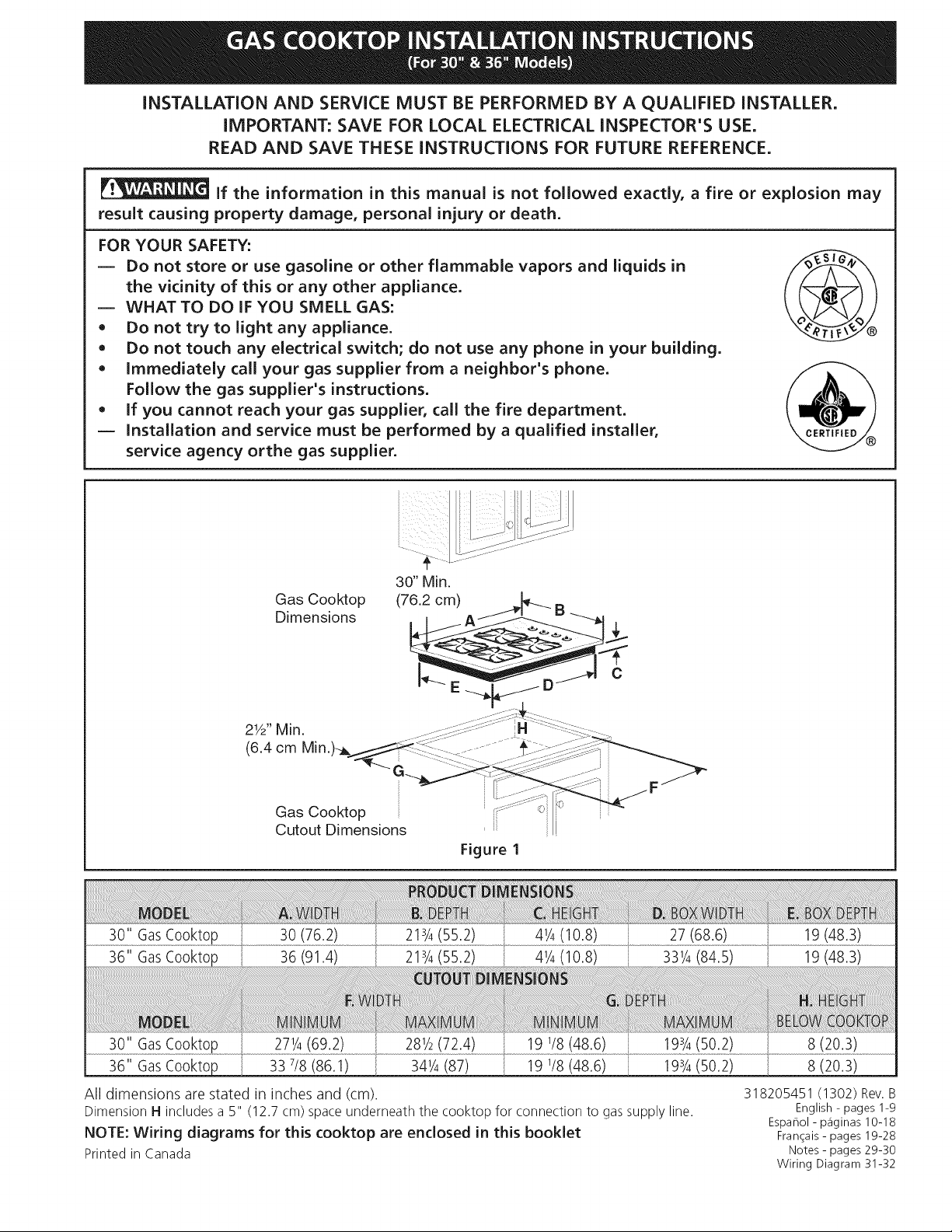
Gas Cooktop
Dimensions
Gas Cooktop
Cutout Dimensions
Figure I
281/2(72.4) 193/4(50.2)
36" GasCooktoL_ 33 7/8(86.1) 341/4(87) 19 1/8(48.6) 193/4(50.2)
All dimensions arestated in inches and (cm).
DimensionH includesa 5" (12.7cm) spaceunderneaththe cooktop for connectionto gassupplyline.
NOTE: Wiring diagrams for this cooktop are enclosed in this booklet
Printedin Canada
8 (20.3)
318205451 (1302) Rev.B
English - pages 1-9
Espahol - p_iginas 10-18
Fran_ais - pages 19-28
Notes - pages 29-30
Wiring Diagram 31-32
Page 2
important Notes to the Installer
1. Read all instructions contained in these installation
instructions before installing the cooktop.
2. Remove all packing material before connecting the
electrical supply to the cooktop.
3. Observe all governing codes and ordinances.
4. Be sure to leave these instructions with the consumer.
5. Note: For operation at 2000 ft. elevations above see
level, appliance rating shall be reduced by 4 percent
for each additional 1000 ft.
important Note to the Consumer
Keep these instructions with your Use and Care Guide for
future reference.
IMPORTANT SAFETY
INSTRUCTION
Installation of this cooktop must conform with local
codes or, in the absence of local codes, with the National
Fuel Gas Code ANSI Z223.1/NFPA 54 in the United
States, or in Canada, with the Canadian Fuel Gas Code,
CAN/CGA B149 and CAN/CGA B149.2.
• When installed in a manufactured (mobile) home
installation must conform with the Manufactured
Home Construction and Safety Standard, title 24 CFR,
part 3280 [Formerly the Federal Standard for Mobile
Home Construction and Safety, title 24, HUD (part
280)] or, when such standard is not applicable, the
Standard for Manufactured Home Installation, ANSI/
NCSBCSA225.1 or with local codes where applicable.
This cooktop has been design certified by CSA
International. As with any appliance using gas and
generating heat, there are certain safety precautions you
should follow. You will find them in the Use and Care
Guide., read it carefully.
Air curtain or other overhead hoods, which operate
by blowing a downward air flow on to a range, shall
not be used in conjunction with gas ranges other
than when the hood and range have been designed,
tested and listen by an independent test laboratory
for use in combination with each other.
Be sure your cooktop is installed and grounded
properly by a qualified installer or service
technician.
This cooktop must be electrically grounded in
accordance with local codes or, in their absence,
with the National Electrical Code ANSI/NFPA
No. 70--latest edition in the United States, or in
Canada, with the Canadian Electrical Code, CSA
C22.1 Part 1.
The burners can be lit manually during an
electrical power outage. To light a burner, hold a
lit match to the burner head, then slowly turn the
Surface Control knob to LITE. Use caution when
lighting burners manually.
Do not store items of interest to children in
cabinets above the cooktop. Children could be
seriously burned climbing on the cooktop to reach
items.
To eliminate the need to reach over the surface
burners, cabinet storage space above the burners
should be avoided.
Adjust surface burner flame size so it does not
extend beyond the edge of the cooking utensil.
Excessiveflame is hazardous.
Never use your cooktop for warming or heating
the room. Prolonged use of the cooktop without
adequate ventilation can be hazardous.
Do not store or use gasoline or other flammable
vapors and liquids near this or any other
appliance. Explosions or fires could result.
The electrical power to the cooktop
must be shut off while gas line connections are
being made. Failure to do so could result in serious
injury or death.
Page 3
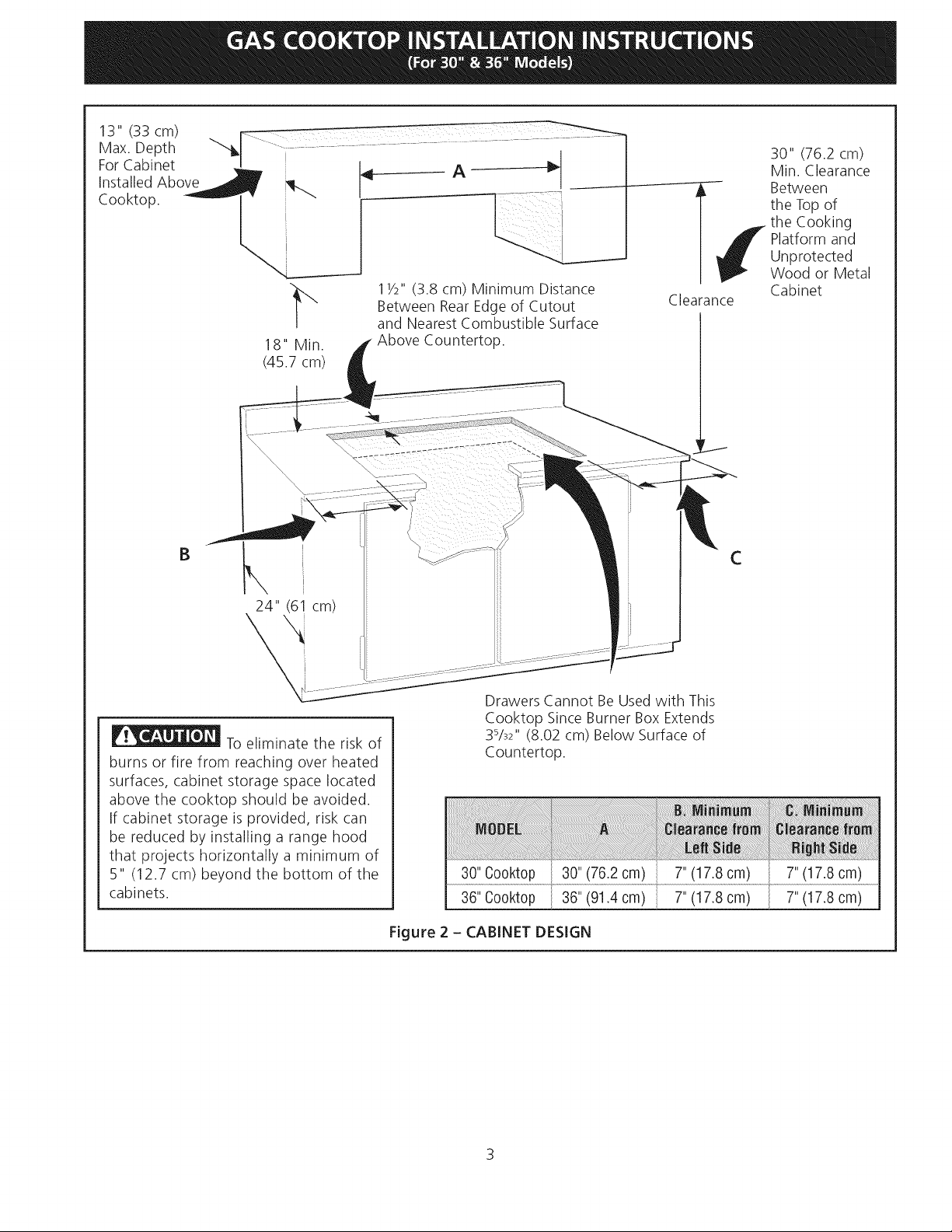
13"(33cm)
Max.Depth
ForCabinet
InstalledAbove
Cooktop.
18"Min.
(45.7cm)
11/2"(3.8cm)MinimumDistance
BetweenRearEdgeofCutout
andNearestCombustibleSurface
AboveCountertop.
30" (76.2 cm)
Min. Clearance
Between
the Top of
the Cooking
Platform and
--T!
Clearance
Unprotected
Wood or Metal
Cabinet
B
24" (6! cm)
2
To eliminate the risk of
burns or fire from reaching over heated
surfaces, cabinet storage space located
above the cooktop should be avoided.
If cabinet storage is provided, risk can
be reduced by installing a range hood
that projects horizontally a minimum of
5" (12.7 cm) beyond the bottom of the
cabinets.
Drawers Cannot Be Used with This
Cooktop Since Burner Box Extends
3%2" (8.02 cm) Below Surface of
Countertop.
36" Cooktop
Figure 2 - CABINET DESIGN
36" (91.4 cm)
C
7"(17.8 cm)
7"(17.8 cm)
7" (17.8 cm)
7" (17.8 cm)
3
Page 4
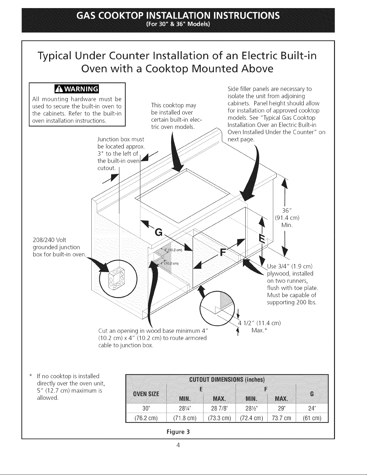
Typical Under
Counter Installation of an Electric Built-in
Oven
All mounting hardware must be
used to secure the built-in oven to
the cabinets. Refer to the built-in
oven installation instructions.
208/240 Volt
grounded junction
box for built-in oven.
with a Cooktop Mounted Above
Junction box must
be located approx.
3" to the left of
the built-in oven
cutout.
This cooktop may
be installed over
certain built-in elec-
tric oven models.
Side filler panels are necessaryto
isolate the unit from adjoining
cabinets. Panel height should allow
for installation of approved cooktop
models. See "Typical Gas Cooktop
Installation Over an Electric Built-in
Oven Installed Under the Counter" on
next page.
36"
(91.4 cm)
Min.
Cut an opening in wood base minimum 4"
(10.2 cm) x 4" (10.2 cm) to route armored
cable to junction box.
If no cooktop is installed
directly over the oven unit,
5" (12.7 cm) maximum is
allowed.
(76.2 cm) (71.8 cm)
Figure 3
Use 3/4" (1.9 cm)
plywood, installed
on two runners,
flush with toe plate.
Must be capable of
supporting 200 Ibs.
4 1/2" (11.4 cm)
Max.*
(73.3 cm) (72.4 cm) 73.7 cm (61 cm)
Page 5
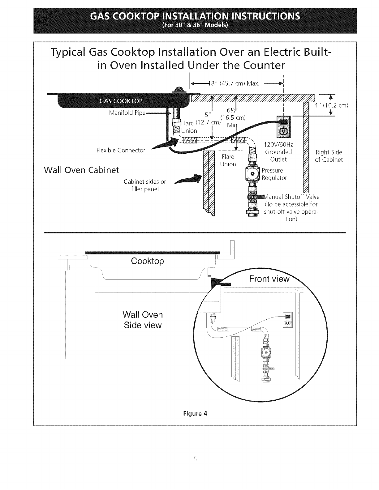
Typical Gas Cooktop Installation Over an Electric Built-
in Oven Installed Under the Counter
I I8" (45.7 cm) Max. ----'_I
I
4" (10.2 cm)
Manifold Pil
Flare (12.7 cm)(1
Union
/i
6.5
cm)
÷
Flexible Connector
Wall Oven Cabinet
Cabinet sides or
filler panel
Wall Oven
Side view
Flare
Union
120V/6OHz
Grounded
Outlet
Pressure
Regulator
(Tobe
shut-off valve op
Front
Right Side
of Cabinet
Shutoff
for
_ra-
tion)
Figure 4
Page 6
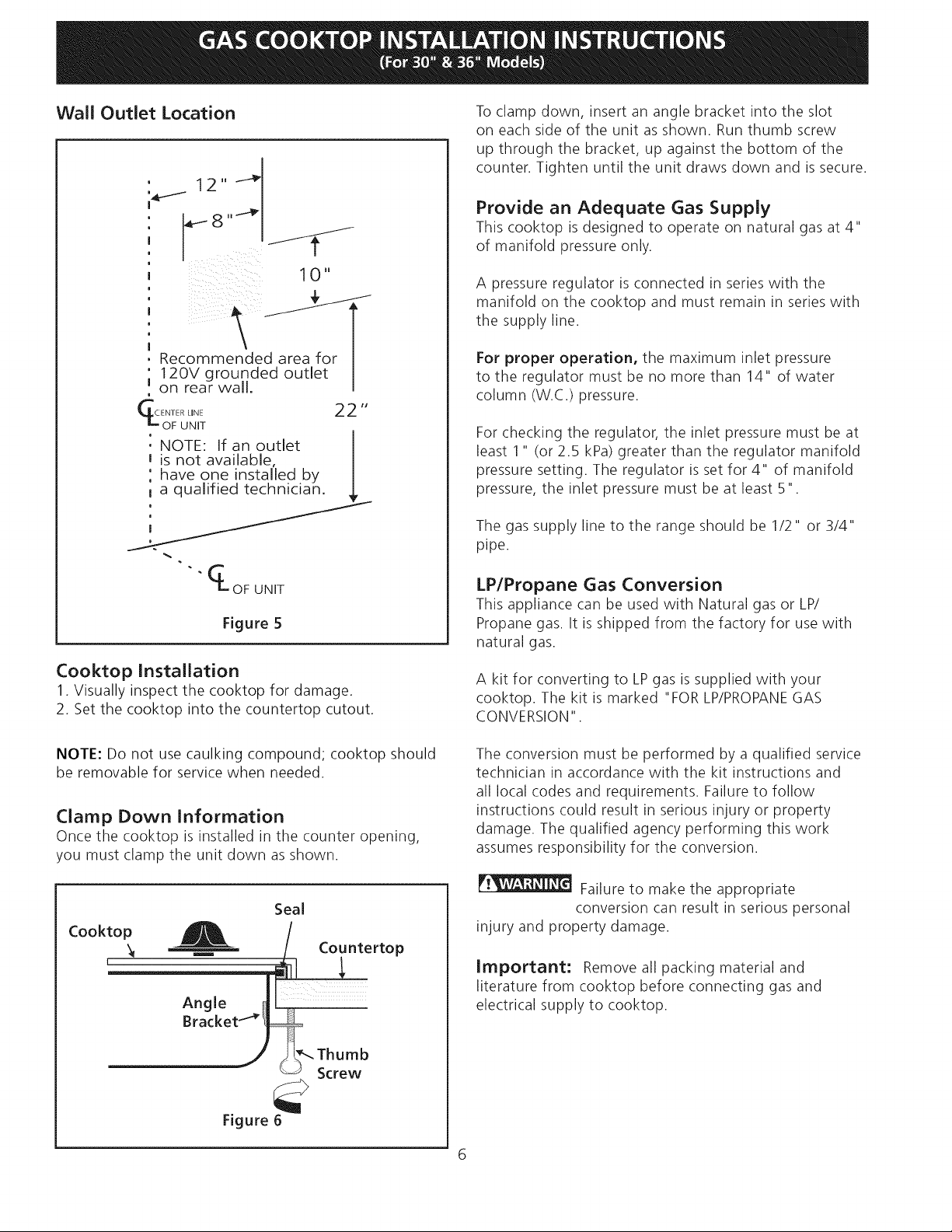
Wall Outlet Location
, 12,, --_
I 1 0 "
o
I
, Recommended area for
' 12OV grounded outlet
u on rear wall.
m
CL_olFUL_ET 22 "
: NOTE: If an outlet
J is not available, I
: have one installed by I
t a qualified technician.
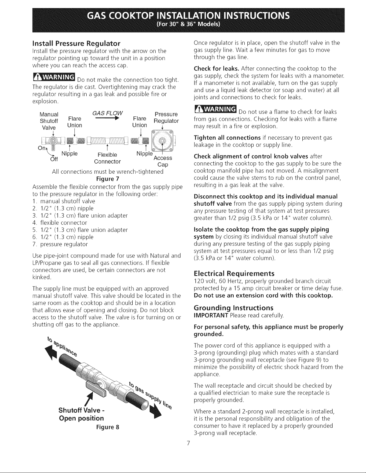
To clamp down, insert an angle bracket into the slot
on each side of the unit as shown. Run thumb screw
up through the bracket, up against the bottom of the
counter. Tighten until the unit draws down and is secure.
Provide an Adequate Gas Supply
This cooktop is designed to operate on natural gas at 4"
of manifold pressure only.
A pressure regulator is connected in series with the
manifold on the cooktop and must remain in series with
the supply line.
For proper operation, the maximum inlet pressure
to the regulator must be no more than 14" of water
column (W.C.) pressure.
For checking the regulator, the inlet pressure must be at
least 1" (or 2.5 kPa) greater than the regulator manifold
pressure setting. The regulator is set for 4" of manifold
pressure, the inlet pressure must be at least 5".
The gas supply line to the range should be 1/2" or 3/4"
pipe.
It OF UNIT
Figure 5
Cooktop Installation
1. Visually inspect the cooktop for damage.
2. Set the cooktop into the countertop cutout.
NOTE: Do not use caulking compound; cooktop should
be removable for service when needed.
Clamp Down Information
Once the cooktop is installed in the counter opening,
you must clamp the unit down as shown.
Seal
Cooktop
x_ _ Countertop
Angle
Bracketl_t(
LP/Propane Gas Conversion
This appliance can be used with Natural gas or LP/
Propane gas. It is shipped from the factory for use with
natural gas.
A kit for converting to LPgas is supplied with your
cooktop. The kit is marked "FOR LP/PROPANEGAS
CONVERSION".
The conversion must be performed by a qualified service
technician in accordance with the kit instructions and
all local codes and requirements. Failure to follow
instructions could result in serious injury or property
damage. The qualified agency performing this work
assumes responsibility for the conversion.
Failure to make the appropriate
conversion can result in serious personal
injury and property damage.
Important: Remove all packing material and
literature from cooktop before connecting gas and
electrical supply to cooktop.
Figure 6
Thumb
Screw
Page 7
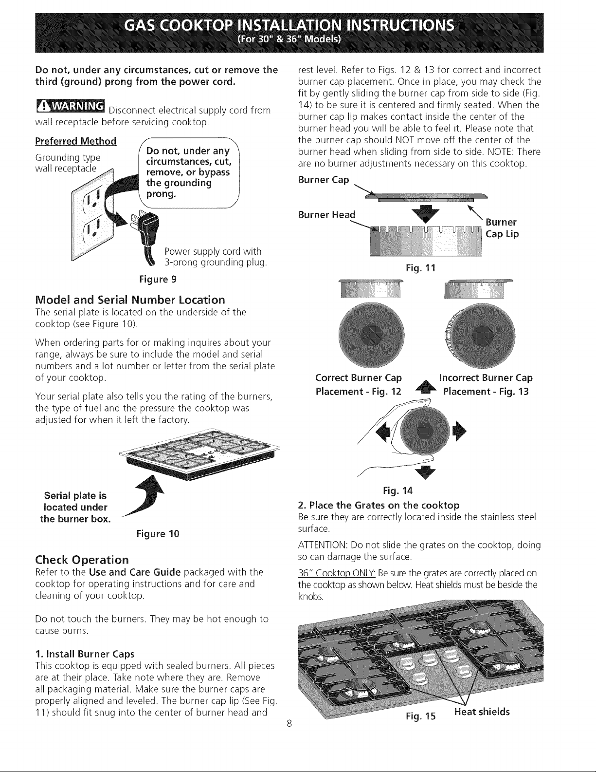
install Pressure Regulator
Install the pressure regulator with the arrow on the
regulator pointing up toward the unit in a position
where you can reach the access cap.
Do not make the connection too tight.
The regulator is die cast. Overtightening may crack the
regulator resulting in a gas leak and possible fire or
explosion.
Manual GAS FLOW Pressure
Shutoff Flare _1_ Flare Regulator
Valve Union Union
On, ltr/ t t ....
Assemble the flexible connector from the gas supply pipe
to the pressure regulator in the following order:
1. manual shutoff valve
2. 1/2" (1.3 cm) nipple
3. 1/2" (1.3 cm) flare union adapter
4. flexible connector
5. 1/2" (1.3 cm) flare union adapter
6. 1/2" (1.3 cm) nipple
7. pressure regulator
Use pipe-joint compound made for use with Natural and
LP/Propane gas to seal all gas connections. If flexible
connectors are used, be certain connectors are not
kinked.
The supply line must be equipped with an approved
manual shutoff valve. This valve should be located in the
same room as the cooktop and should be in a location
that allows ease of opening and closing. Do not block
access to the shutoff valve. The valve isfor turning on or
shutting off gas to the appliance.
Nipple Flexible Nipple
Off Connector
All connections must be wrench-tightened
Figure 7
Access
Cap
Once regulator is in place, open the shutoff valve in the
gas supply line. Wait a few minutes for gas to move
through the gas line.
Check for leaks. After connecting the cooktop to the
gas supply, check the system for leaks with a manometer.
if a manometer is not available, turn on the gas supply
and use a liquid leak detector (or soap and water) at all
joints and connections to check for leaks.
Do not use a flame to check for leaks
from gas connections. Checking for leaks with a flame
may result in a fire or explosion.
Tighten all connections if necessary to prevent gas
leakage in the cooktop or supply line.
Check alignment of control knob valves after
connecting the cooktop to the gas supply to be sure the
cooktop manifold pipe has not moved. A misalignment
could cause the valve stems to rub on the control panel,
resulting in a gas leak at the valve.
Disconnect this cooktop and its individual manual
shutoff valve from the gas supply piping system during
any pressure testing of that system at test pressures
greater than 1/2 psig (3.5 kPa or 14" water column).
Isolate the cooktop from the gas supply piping
system by closing its individual manual shutoff valve
during any pressure testing of the gas supply piping
system at test pressures equal to or less than 1/2 psig
(3.5 kPa or 14" water column).
Electrical Requirements
120 volt, 60 Hertz, properly grounded branch circuit
protected by a 15 amp circuit breaker or time delay fuse.
Do not use an extension cord with this cooktop,
Grounding Instructions
IMPORTANT Pleaseread carefully.
For personal safety, this appliance must be properly
grounded,
Shutoff Valve -
Open position
Figure 8
The power cord of this appliance is equipped with a
3-prong (grounding) plug which mates with a standard
3-prong grounding wall receptacle (see Figure 9) to
minimize the possibility of electric shock hazard from the
appliance.
The wall receptacle and circuit should be checked by
a qualified electrician to make sure the receptacle is
properly grounded.
Where a standard 2-prong wall receptacle is installed,
it is the personal responsibility and obligation of the
consumer to have it replaced by a properly grounded
3-prong wall receptacle.
7
Page 8
Donot,underanycircumstances,cutor removethe
third (ground)prongfromthepowercord.
Disconnectelectricalsupplycordfrom
wallreceptaclebeforeservicingcooktop.
Preferred Method
Grounding type
wall receptacle
Model and Serial Number Location
The serial plate is located on the underside of the
cooktop (see Figure 10).
When ordering parts for or making inquires about your
range, always be sure to include the model and serial
numbers and a lot number or letter from the serial plate
of your cooktop.
Your serial plate also tells you the rating of the burners,
the type of fuel and the pressure the cooktop was
adjusted for when it left the factory.
not, under any
circumstances, cut,
remove, or bypass
the grounding
prong.
Power supply cord with
3-prong grounding plug.
Figure 9
rest level. Refer to Figs. 12 & 13 for correct and incorrect
burner cap placement. Once in place, you may check the
fit by gently sliding the burner cap from side to side (Fig.
14) to be sure it is centered and firmly seated. When the
burner cap lip makes contact inside the center of the
burner head you will be able to feel it. Please note that
the burner cap should NOT move off the center of the
burner head when sliding from side to side. NOTE: There
are no burner adjustments necessary on this cooktop.
Burner Cap
Burner Head "_ _ Burner
Cap Lip
Fig. 11
Correct Burner Cap _ Incorrect Burner Cap
Placement- Fig. 12 _ Placement- Fig. 13
Serial plate is
located under
the burner box.
Figure 10
Check Operation
Refer to the Use and Care Guide packaged with the
cooktop for operating instructions and for care and
cleaning of your cooktop.
Do not touch the burners. They may be hot enough to
cause burns.
1. Install Burner Caps
This cooktop is equipped with sealed burners. All pieces
are at their place. Take note where they are. Remove
all packaging material. Make sure the burner caps are
properly aligned and leveled. The burner cap lip (See Fig.
11) should fit snug into the center of burner head and
Fig. 14
2. Place the Grates on the cooktop
Be sure they are correctly located inside the stainless steel
surface.
ATTENTION:Do not slide the grates on the cooktop, doing
so can damage the surface.
36" Cooktop ONLY:Besurethe grates arecorrectlyplaced on
the cooktop asshown below. Heat shieldsmust be besidethe
knobs.
Fig. 15
Heat shields
Page 9
,
Turn on Electrical Power and Open Main Shutoff
Gas Valve
,
Check the Igniters
Operation of electric igniters should be checked
after cooktop and supply line connectors have been
carefully checked for leaks and the cooktop has been
connected to electric power.
To operate the surface burner:
A. Push in and turn a surface burner knob to the
LITEposition. You will hear a small ticking noise;
this is the sound of the electric ignitor which
lights the burner.
B. After the burner lights, turn to the desired flame
size. The controls do not have to be set at a
particular mark. Usethe marks as a guide and
adjust the flame as needed.
5.
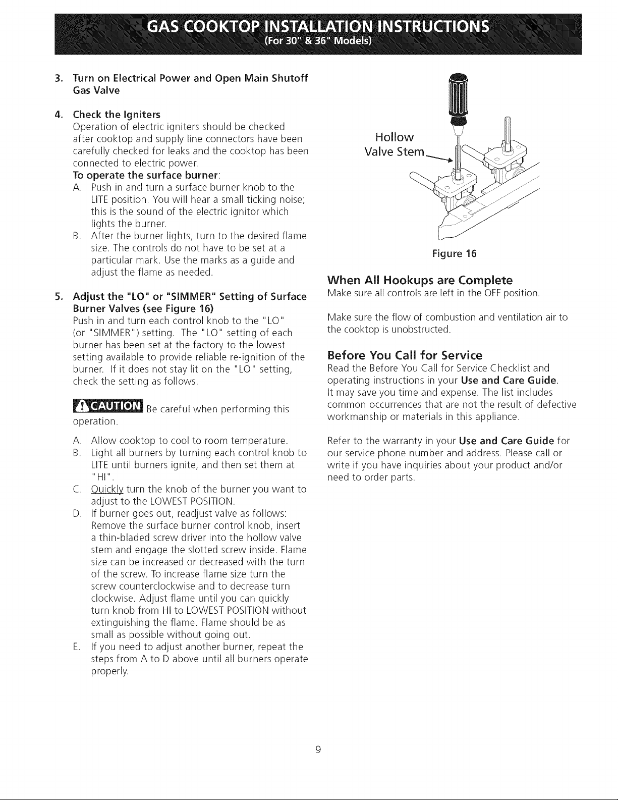
Adjust the "LO" or "SIMMER" Setting of Surface
Burner Valves (see Figure 16)
Push in and turn each control knob to the "LO"
(or "SIMMER") setting. The "LO" setting of each
burner has been set at the factory to the lowest
setting available to provide reliable re-ignition of the
burner. If it does not stay lit on the "LO" setting,
check the setting as follows.
Be careful when performing this
operation.
Hollow
Valve Stem_
Figure 16
When All Hookups are Complete
Make sure all controls are left in the OFFposition.
Make sure the flow of combustion and ventilation air to
the cooktop is unobstructed.
Before You Call for Service
Read the Before You Call for Service Checklist and
operating instructions in your Use and Care Guide.
It may save you time and expense. The list includes
common occurrences that are not the result of defective
workmanship or materials in this appliance.
A. Allow cooktop to cool to room temperature.
B. Light all burners by turning each control knob to
LITEuntil burners ignite, and then set them at
"HI".
C. _ turn the knob of the burner you want to
adjust to the LOWEST POSITION.
D. If burner goes out, readjust valve as follows:
Remove the surface burner control knob, insert
a thin-bladed screw driver into the hollow valve
stem and engage the slotted screw inside. Flame
size can be increased or decreased with the turn
of the screw. To increase flame size turn the
screw counterclockwise and to decrease turn
clockwise. Adjust flame until you can quickly
turn knob from HI to LOWESTPOSITIONwithout
extinguishing the flame. Flame should be as
small as possible without going out.
E. If you need to adjust another burner, repeat the
steps from A to D above until all burners operate
properly.
Refer to the warranty in your Use and Care Guide for
our service phone number and address. Please call or
write if you have inquiries about your product and/or
need to order parts.
9
Page 10
LA INSTALACION Y EL SERVICIO DEBEN SER REAUZADOS POR UN INSTALADOR CALIFICADO.
IMPORTANTE: GUARDE ESTAS INSTRUCCIONES PARA USO DEL iNSPECTOR ELI__CTRICOLOCAL.
LEA Y GUARDE ESTAS INSTRUCCIONES PARA FUTURAS REFERENCIAS
Si todas las instrucciones de _ste manual no son observadas a la letra, se puede
ocurrir incendios o explosiones que pueden causar daEos materiales, lesiones o la muerte.
PARA SU SEGURIDAD:
-- No almacene o utilice gasolina u otros vapores y liquidos inflamables cerca
de _ste o cualquier otro artefacto.
-- QUE HACER SI HAY FUGAS DE GAS :
• No intente de encender ningun artefacto
®
No toque ningun interruptor el_ctrico; no utilice ningun aparato telef6nico en su edificio.
Llame inmediatamente el abastecedor de gas desde el tel_fono de un vecino.
Siga las instrucciones del abastecedor de gas.
En caso que no puede contactar el abastecedor de gas Ilame al departamento de
bomberos.
--La instalacion y el servicio t_lefonico deben ser realizados por un instalador
calificado, por un servicio tecnico certificado o por el abastecedor de gas.
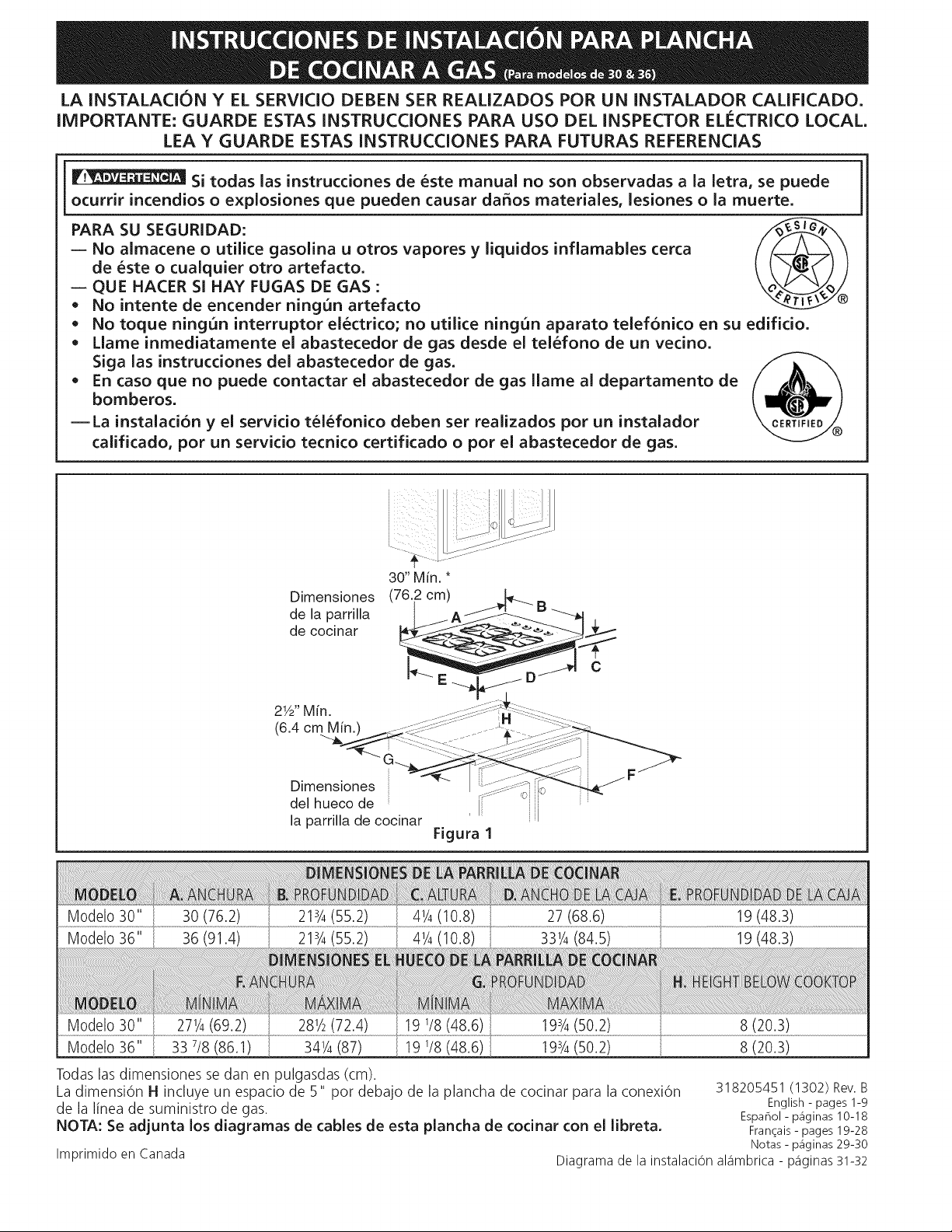
Modelo 36"
Modelo 36"
Dimensiones
de la parrilla
de cocinar
2W' Min.
(6.4 cm Min.
Dimensiones
del hueco de
la parrilla de cocinar
Figura I
30 (76.2)
36 (91.4)
213/4(55.2)
213/4(55.2) 41/4(10.8) 331/4(84.5) 19 (48.3)
281/2(72.4) 19 1/8(48.6) 195/4(50.2)
33 7/8(86.1) 341/4(87) 19 1/8(48.6) 193/4(50.2)
8 (20.3)
8 (20,3)
Todas las dimensiones se dan en pulgasdas (cm).
La dimensi6n H incluye un espacio de 5" pot debajo de la plancha de cocinar para la conex16n 318205451 (1302) Rev.B
de la linea de suministro de gas. English- pages 1-9
Espahol - p_iginas 10-18
NOTA: Se adjunta los diagramas de cables de esta plancha de codnar con el libreta. Fran_ais-pages19-28
Imprimido en Canada Diagramade lainstalaci6nal_imbrica- p_iginas31-32
Notas - p_iginas 29-30
Page 11

Notas importantes para el instalador:
1. Leatodas las instrucciones de instalaciOn antes de
realizar la instalaci6n de la plancha de cocinar.
2. Retire todos los articulos de embalaje antes de realizar
lasconexiones el_ctricas a la plancha de cocinar.
3. Observe todos los c6digos o reglamentos estatales
4. Aseg0rese que el consumidor tenga estas instrucciones.
5. Nota: Para el correcto funcionamiento en lugares
superiores a los 2000 ft, el r_gimen del mecanismo debe
reducirse un 4% pot cada 1000 ft sobre el nivel del mar.
Notas importantes para el consumidor
Guarcle todas las instrucciones con su manual del usuario
para futuras referiencias.
INSTRUCCIONES DE
SEGURIDAD IMPORTANTES
La instalaciOn de esta plancha de cocinar debe realizarse
en conformidad con los c6digos locales o, si estos no
existen, con el National Fuel Gas Code ANSI Z223.1/NFPA
54 en los Estados Unidos, o en Canada, con el Canadian
Fuel Gas Code, CAN/CGA B149 y CAN/CGA B149.2.
• La instalaciOn de aparatos diseflados para instalaciOn
en casas prefabricadas (m6viles) debe conformar con el
Maufactured Home Consturction and Safet Standard,
titulo 24CFR, parte 3280 [Anteriormente el Federal
Standard for Mobil Home Construction and Safety,
titulo 24, HUD (parte 280)] o cuando tal est_indar no se
aplica, el Standard fo Manufactured Home Installation,
ANSI/NCSBCS 225.1, o con los c6digos locales.
El diseho de esta plancha de cocinar cuenta con la
aprobaci6n de la CSA internacional. AI igual que todos los
artefactos a gas que generan calor, deben seguirse ciertas
medidas de seguridad. Vienen con el Manual del Usuario.
Lea atentamente el manual.
• No se deben usar cortinas de aire ni ninguna
otra campana de ventilacion superior que sople
aire hacia abajo sobre la estufa a gas a menos
que la campana de ventilaci6n y la estufa hayan
sido dise_adas, probadas y certificadas pot un
laboratorio de pruebas independiente para el uso
combinado de la una con la otra.
Asegurese que la plancha de cocinar sea instalada
y puesta a tierra correctamente pot un instalador
o t_cnico calificado.
La plancha de cocinar debe conectarse
el_ctricamente a tierra de acuerdo con los codigos
locales o, de no existir, con el codigo el_ctrico
ANSI/NFPA No. 70 =ultima edicion en los Estados
Unidos, or in Canada, con el Canadian Electrical
Code, CSA C22.1 Parte 1.
Los quemadores pueden encenderse
manualmente durante una interrupcion del
suministro el_ctrico. Para encender un quemador,
mantenga un fosforo encendido en el extremo del
quemador, luego gire suavemente la perilla hasta
LITE (encendido). Tenga cuidado al encender los
quemadores en forma manual.
No deje articulos que interesan los ni_os en los
armarios que est_n sobre la la plancha de cocinar.
Les podria causar quemaduras graves si intentan
subirse para alcanzarlos.
Para eliminar el riesgo de extender pot encima
de los quemadores superiores, deberia evitar
el espacio de almacenamiento del armario,
Iocalizado pot encima de estos quemadores
Gradue el tama_o de la llama de modo que
no sobrepase el borde del utensilio de cocina.
Demasiada llama es peligrosa.
• No utilice jamas la cocina como calefactor. Eluso
prolongado de la cocina sin la ventilaci6n adecuada
puede set peligroso.
Mantenga el area cerca de este artefacto
o de cualquier otto artefacto despejada de
sustancias combustibles, gasolina y otros Iiquidos
inflamables. Se puecle ocurrir incendios o explosiones.
i!_ El suministro electrico a la plancha
de cocinar debe de set cerrado durante las
conexiones a la linea.m De Io contrario se puede
resultar lesiones graves o la muerte.
Ubicacion de ia toma de corriente de ia
pared
' 12"
,
I-
I 10"
I
_,rea recomendada la toma de
, corriente a tierra de 120V en Wa
I pared posterior,
J
APARATO
_LDEL 2 2"
NOTA: Si no existe una toma /
de corriente, contacte a un
eJectricista calificado para
realizar Ja instalaci6n.
- Figura 5
" _JLDEL APARATO
/
1_
11
Page 12

M_ix.profundidad
de gabinetes
instalados pot
encima de la
plancha de
empotar es 13"
(33 cm).
18" Min.
(45.7 cm)
24" (61 cm_
11/2"(3.8 cm) Minimo Distancia
entre el horde posterior del
hueco y lamas cerca superficie
combustible pot encima del
mostrador.
_T_430" (76.2
cm) Minimo
de espacio
entre la parte
I i la plataforma
Esoacio de la plancha
superior de
de cocinar y
el fondo de
una madera
non protegida
o armario
metalico.
C
\
Para eliminar el
riesgo de alargar sobre los unidades en
calentamiento de la superficie, deberia
evitarse el espacio de almacenamiento del
armario, ubicado sobre las unidades de la
superficie. Si se cuenta con este espacio,
se puede disminuir el peligro instalando
una cubierta de cocina que se extienda
horizontalmente en 5" (12.7 cm) minimo
pot sobre la parte inferior delantera en
los armarios.
Figura 2- DESENO DEL ARMARIO
No es posible utilizar cajones con
esta parrilla de cocinar porqu@ la
caja de empalme se extiende de
3%2" (8.02 cm) pot encima de la
superficie del mostrador.
30" (76.2 cm) 7"(17.8 cm)
36" (91.4 cm) 7"(17.8 cm)
7"(17.8 cm)
7"(17.8 cm)
12
Page 13

Tipica instalaci6n de un horno el ctrico empotrado con una
plancha de cocinar por encima
Entrepa_os Ilenador de lados son
necesarios para aislar el aparato de
los armarios adyacentes. La altura de
Todas las fijaciones de
montaje deben de estar
utilizadas para sujetar
el homo empotrado a
los armarios. Refiere
a las instrucciones de
instalaci6n del homo
empotrado.
Esta plancha de cocinar puede instalarse
por encima de algunos modelos de homo
electrico empotrado.
Aproximadamente 3"
(7.6
panel debe de permitir la instalaci6n
de modelos de planchas de cocinar
aprobantes. Ver "lnstalaciOn t[pica de
plancha de cocinar a gas por encima de
un homo electrico empotrado instalado
debajo del mostrador" en la pagina 4.
36"
(91.4 cm)
"- Minimo
Caja de empalme a tierra de
208/240 voltaje para homo
empotrado
* (Si no hay plancha de cocinar
instalada directamente sobre
el aparato, un maximo de 5"
(12.7 cm) esta permitido)
** Un minimo de 32" (81.3 cm)
desde la parte superior del
armario hasta la parte superior
de las ruedas debe de set
mantenido.
Corte una abertura en la basa de madera
m[nimo 4" (10.2 cm) x 4" (10.2 cm) para
conducir elcable blindado a la caja de
empalme.
30"
(76.2 cm) (71.8 cm)
Figura 3
(73.3 cm)
Utilice 3/4" (1.9 cm) de madera
contrachapada, instalada sobre 2 ruedas,
perpendicular a una cima de contomo de
)laca. Debe de poder sostener 150 Ibs.
41/2" Max.*
1.4 cm)
(72.4 cm)73.7 cm
(61 cm)
13
Page 14

Instalacion tipica de la plancha de cocinar a gas por encima de un horno
electrico empotrado instalado debajo del mostrador
I I
._ 18" (45.7 cm) M&x."-""_I
÷
4" (I0.2cm)
Tubomulti
61/2"
5" (13.5 cm)
(12.7 cm) Min.
UniOn
Conector
Cabinet sides or
filler panel
Armario del homo de pared
ESTUFA DE GAS
UniOn
Vista anterior
UniOn
120Vl6OHzToma
de cordente a
tierra
Regulador de
presiOn
V&Ivula de derre manual
(Debe de ser accesible para el
fundona-miento de la v&Ivula
de derre)
Lado derecho
del armado
Vista de lado del
homo de pared
Figura 4
14
Page 15

Instalaci6n de ia piancha de cocinar
1, Examine visualmente la plancha de cocinar para saber
si hay daho,
2, Fije el la plancha de cocinar en el recorte del
mostrador,
Inforrnacion para sujetar el aparato
Una vez que el aparato est,1instalado en la apertura del
mostrador, se tiene que sujetar como se indica.
Planchade Junta de estanqueidad
cocinar A /
_ / Mostrador
i H
.,_ _" TomiellOsde
Figura _
Para ajustar el aparato, inserte la consola de escuadra, con
el lado desviado, en lasranuras en cada lado del aparato.
El tornillo de orejas debe entonces de pasar a trav_s del
soporte y hasta la parte de abajo del mostrador. Apri_telo
hasta que el aparato se quede ajustado.
Provea un adecuado surninistro de gas
Esta plancha de cocinar est,1disehada para utilizar gas
natural de 4" de presiOn m01tiple solamente.
Se conecta un regulador de presiOn en serie al m01tiple de
la plancha de cocinar y debe permanecer en serie con la
linea de suministro de gas.
Para que manejo correcto, la presiOnde entrada m_ixima
hacia el regulador no debe exceder 14" de presiOn de la
columna de agua.
Para controlar el regulador, la presi6n de entrada debe
ser de al menos 1" (o 2.5 Kpa) mayor que el ajuste de la
presi6n del mOltiple del regulador. El regulador se ajusta a
4" de la presi6n del mOltiple, la presi6n de entrada debe
de ser de al menos 5".
La linea de suministro de gas por el homo deberia tener un
tubo de 1/2" o de 3/4".
Conversion de gas propano/licuado
Esta plancha de cocinar ha sido disehada para utilizar gas
natural o gas propano. Ha sido fijada en la f_ibrica para
utilizarse con gas natural.
Si desea hacer la conversion para utilizar el gas propano,
use las piezas con orificios fijados provistos en el
paquete del manual de instrucciones para la instalaciOn
en el paquete escrito "PARA LA CONVERSIONEN GAS
PROPANO". Siga lasinstrucciones que est_incon los
orificios.
Para hacer la conversion del gas natural al gas propano,
es necesario utilizar el servicio de un t_cnico calificado,
in acuerdo con las instrucciones del fabricante y todos
los cOdigos y reglamentos reguladores. Si todas las
instrucciones no son observadas, se puede ocurrir severos
lesiones o dahos materiales. La agencia calificada que hace
el trabajo asuma la responsabilidad para la conversion.
Si la conversion apropiada no esta
observada, se puede ocurrir severos lesiones o dahos
materiales.
Importante: Retire todos los articulos de embalaje y
folletos de la cocina antes de realizar las conexiones de gas
y el_ctricas a la cocina.
Instalaci6n del regulador de presion
Instale el regulador de presiOn con la flecha del regulador
apuntando hacia la unidad en una posici6n que permita
alcanzar la tapa de entrada.
No ajuste demasiado la conexi6n. El
regular est,1fundida a presi6n. AI ajustar demasiado se
puede romper el regulador causando una fuga de gas y un
posible incendio o explosi6n.
Valvula de FLUJO DEL GAS Regulator
cierre UniOn Uni6n
manual
Abierto _ t iI
(on) _ Boquilla Conector II
Apagado flexible Tapade
(Off) entrada
Todas las conexiones deben ajustarse con
Monte el conector flexible del tubo del suministro de gas al
regulador de presiOn en funcionamiento:
1. wilvula de cierre manual
2. boquilla de 1/2" (1.3 cm)
3. adaptor de 1/2" (1.3 cm)
4. conector flexible
5. adaptator de 1/2" (1.3 cm)
6. boquilla de 1/2" (1.3 cm)
7. regulador de presiOn.
Utilice un compuesto de tubo articulado para uso de gas
natural y propano para sellar todas las conexiones de
gas. Si se utilizan conectores flexibles, aseg0rese que los
conectores no est_intorcidos.
El tubo de suministro de gas deberia incluir una wilvula de
cierre certificada. Estawilvula deberia estar ubicada en la
misma habitaciOn de la plancha de cocinar y deberia estar
en un lugar que permita una abertura y cierre f_iciles. No
bloquee las entradas de la wilvula de cierre. La wilvula sirve
para abrir o cerrar el paso del gas al artefacto.
15
_ de presi6n
una Ilave de tuerca
Figura 7
Page 16

V_lvula de cierre =
Abierta
Figura 8
Abra la wilvula de cierre en el tubo de suministro de gas.
Espere unos minutos para que el gas pase a trav_s del tubo
de gas.
Verifique si hay fugas. Luego de conectar la cocina al
gas, verifique elsistema con un manOmetro. Si no cuenta
con _ste instrumento, d_ la vuelta al suministro de gas de
la cocina y utilice un detector de fugas liquidas (o agua
yjabOn) en todas las articulaciones y conexiones para
verificar si existen fugas.
No use ning0n tipo de llama para
verificar si hay fugas de gas. Verifique si hay fugas con una
llama puede ocasionar incendio o explosi6n.
Ajuste todas las conexiones en caso que sea necesario,
para evitar fugas de gas en la cocina o en el tubo de
suministro de gas.
Verifique la alineaci6n de las v_lvulas luego de
conectar la plancha de cocinar al suministro de gas para
asegurar que no se ha movido lawilvula del m01tiple de la
plancha de cocinar.
Desconecte la cocina y su v_lvula de cierre individual
del sistema detuberia del suministro de gas durante cualquier
ensayo de presi6n del sistemaen ensayos de presi6n
superiores a 1/2 psig (3.5 kPao 14" columna de agua).
Aparte la cocina del sistema de tuberia del suministro
de gas cerrando su wilvula de cierre individual manual,
durante cualquier ensayo de presi6n del sistema de
suministro de gas en ensayos iguales o inferiores a 1/2 psig
(3.5 kPao 14" columna de agua).
disminuir la posibilidad de peligro de choques el@ctricos
desde el artefacto.
Un electricista calificado debe verificar el enchufe de pared
y el circuito para asegurar que el enchufe est_qconectado a
tierra correctamente.
En caso de encontrarse con un enchufe de pared de dos
patas, es la personal responsabilidad y la obligaci6n del
consumidor reemplazarlo por el enchufe de pared a tierra
de tres patas correspondiente.
No debe, bajo ninguna circunstancia cortar o retirar
la tercera pata (tierra) del cable de encendido.
Desconecte el cable del suministro
el#ctrico del enchufe de pared antes de reparar la plancha
de cocinar.
M F:TODO PREFERIDO
Enchure de
pared a tierra
Figura 9
bajo
encendido,
Cablo de encendido
con enchufe de tres
patas a tierra
Modeio y ubicacion del nurnero de serie
La placa de n0mero de serie est_qubicada en el lado de
abajo de la caja de quemadores (vea la figura 10).
Aseg0rese de incluir el modelo, n0mero de serie y el
n0mero o letra del Iote que se encuentran en la placa, en
todo pedido de partes o solicitud de informaci6n acerca de
su plancha de cocinar.
La placa de n0mero de serie tambi@n indica las
especificaciones de los quemadores, el tipo de combustible
y la presi6n para la cual fue ajustada la plancha de cocinar
en la f_ibrica.
Requerimientos electricos
Un circuito derivado conectado correctamente a tierra de 120
voltios, 60 Hertz protegido por un interruptor autom_qticode
15 amp o un fusible de retardo. No utilice un cable flexible
de extensi6n en esta plancha de cocinar.
Instrucciones para la puesta a tierra
IMPORTANTE Pot favor, lea atentamente.
Como medida de seguridad personal, est_ artefacto
debe conectarse a tierra correctamente.
El cable de encendido de este artefacto incluye un enchufe
de tres patas (a tierra) que calza con un enchufe de pared
de tres patas de conexi6n a tierra (ver Figura 9) para
La placa de serie
est_ ubicada
bajo la hornilla.
16
Figura 10
Page 17

Verifique ia operacion
Refiera al Manual del Usuario que viene con la plancha
de cocinar para las instrucciones de funcionamiento y el
mantenimiento y la limpieza de su plancha de cocinar.
No toque a los quemadores. Pueden estar suficientemente
calientes par causar quemaduras.
1. Instalacion de las tapas de quemadores
Esta plancha de cocinar est,1equipada con quemadores
sellados. Todas las piezas est_inen su lugar. Tome nota
en donde est_in.Quite todo el material de protecci6n.
Elreborde de la tapa del quemador (veala Fig. 11)
debe calzar firmemente en el centro de la cabeza del
quemador y quedar nivelado. Consulte la figuras 12 y
13 para conocer lasmaneras correctas e incorrectas de
colocar la tapa del quemador. Una vez que est# en su
lugar, puede verificar si cabe deslizando suavemente
la tapa del quemador de lado a lado (Fig 14) para
asegurarse de que est# centrada y firmemente asentada.
Cuando el reborde de la tapa del quemador haga
contacto en el centro de la cabeza del quemador, podr_i
escuchar un chasquido. Tengaen cuenta que la tapa del
quemador NO se debe mover del centro de la cabeza del
quemador cuando intente moverla de lado a lado. NOTA:
No es necesario realizar ajustes en los quemadores de
esta plancha de cocinar.
Tapa del
quemador
Cabeza del
quemador
Fig. 11
_'x_' Reborde de
la tapa del
quemador
2. Coloque las parrillas en la tabla de codna
Aseg0rese que las parrillas est_in bien Iocalizadas dentro de
la superficie de acero inoxidable.
ATENCION- no deslice las parrillas dentro de la tabla de
cocina esto puede provocar da_os.
Tablade cocina 36" SOLAMENTE: aseg0rese que las parri-
Ilas est_n colocadas correctamente dentro de la tabla de
cocina como se muestra en la fig. 15, el escudo protector
de calor debe de encontrarse del lado de las perillas.
Escudo protector
de calor
Fig.15
=
Abre el suministro electrico y la wilvula de cierre
principal del gas.
=
Verifique los dispositivos de encendido
La manipulaciOn de los dispositivos de encendido
el_ctrico deberia verificarse tras haber revisado
detenidamente la plancha de cocinar y los conectores
del tubo del suministro de fugas y tras haber conectado
la plancha de cocinar al suministro el_ctrico.
Para operar en la superficie del quemador:
A. Presione y gire la perilla de control hasta LITE.Se
escuchar_ia un pequeho ruido. Estees el ruido
producido pot el dispositivo de encendido el_ctrico
cuando enciende el quemador.
B. Una vez que el quemador est,1encendido, gire
hasta obtener el tamaho de la llama deseada. No
es necesario ajustar los controles en una marca
determinada. Use las marcas como guia y ajuste la
llama seg0n se desea.
Colocaci6n correcta de Colocaci6n incorrecta
la tapa del quemador= de la tapa del
Fig. 12 quemador= Fig. 13
Fig. 14
17
Page 18

5. Verifiqueelajuste"LO" O "SIMMER" de las v_lvulas
de superficie de quemador (vet Figura 16)
Presioney gire el bot0n de control al ajuste "LO" (o
"SIMMER"). Elajuste "LO" de cada quemador ha
sido creado en la f_ibrica para fijarse al menor ajuste
disponible para entregar un re encendido confiable
del quemador. Si no queda encendido en el ajuste
"LO", verifique el ajuste "LO" como se muestra a
continuaciOn.
A. Deje que la cocina seenfrie a temperatura
ambiente.
B. Enciende todos los quemadores girando cada bot6n
de control hasta LITEpara encender los quemadores
y fijarlos en "HI".
C. Gire r@idamente el quemador hasta LOWEST
POSITION.
D. Si el quemador se apaga, reajuste la wilvula como
se muestra a continuaciOn:
Retire el bot6n de control del quemador, inserte un
destornillador de cuchillo delgado en el w%tago del
agujero de la wilvula y encaje el tornillo ranurado. El
tamaho de la llama se puede aumentar o disminuir
girando eltornillo. Grad0e la llama hasta que se
pueda girar r@idamente hacia abajo desde HI
hasta LOWESTPOSITIONsin apagar la llama. La
llama deberia set Io m_qsbaja posible y estable sin
apagarse.
E. Si se desea ajustar otto quemador, repita los pasos
de A a D descritos hasta que los quemadores
funcionen correctamente.
Cuando se ban realizado todos los sisternas
de conexion
Aseg0rese que todos los controlos est_qnen la posici0n de
OFF(apagado).
Aseg0rese que el flujo de combusti6n y ventilaci6n de aire
de la cocina no est_qnobstruidos
Antes de ilarnar ai servicio
Lea la secciOn Lista de Control de Averias en su Manual
del Usuario. Esto le podr_i ahorrar tiempo y gastos. Esta
lista incluye ocurrencias comunes que no son el resultado
de defectos de materiales o fabricaci6n de este artefacto.
Lea la garantia y la informaci6n sobre el servicio en su
Manual del Usuario para obtener el n0mero de tel@fono
y la direcci6n del servicio. Pot favor Ilame o escriba si
tiene preguntas acerca de su estufa o necesita repuestos.
El hueco del
w%tago de la
wilvula
Figura 16
18
Page 19

UN INSTALLATEURQUALIFII_ DOlT EFFECTUERL'INSTALLATIONET LESERVICE
iMPORTANT: CONSERVEZCESiNSTRUCTiONSPOUR LESINSPECTEURSLOCAUX.
LISEZCESiNSTRUCTiONSETCONSERVEZ-LESPOUR Ri_FI_RENCESULTI_RIEURES.
r.,:\/:l.li[--]--]:lul:l_il Sl les instructions de ce manuel ne sont pas sulvles aw , v - v _ ...... la lettre, il pourrait en r_sulter un
[incendie ou une exp os on suscept b e de causer des dommages mater e s, des blessures ou m_me la mort.
POUR VOTRE SI_CURITI_:
-- N'entreposez et n'utilisez pas d'essence ou d'autres produits inflammables a proximite de
cet appareil ou de tout autre appareil.
-- QUE FAIRE SI VOUS Dt_CELEZUNE ODEUR DE GAZ:
• Ne tentez d'allumer aucun appareil.
• N'actionnez aucun interrupteur _lectrique; n'utilisez aucun appareil telephonique de I'edifice.
• Communiquez imm_diatement avec votre fournisseur de gaz en vous servant du telephone
d'un voisin. Suivez les instructions que le fournisseur vous donnera.
• S'il vous est impossible de rejoindre votre distributeur de gaz, communiquez avec le service
d'incendie.
-- L'installation et I'entretien doivent _tre effectues par un installateur qualifi& un service
d'entretien ou de reparation accredite ou le distributeur de gaz.
Dimensions de la
plaque de cuisson
2Y2"Min.
(6.4 cm Min.
Dimensions de d_coupage
pour la plaque de cuisson
Figure 1
19 1/8(48.6)
Moddes 36" 33 7/8(86.1) 341/4(87)
193/4(50,2) 8 (20,3)
Toutes les dimensions sont en pouces (cm). 318205451 (1302) Rev.B
La dimension H est le d_gagement requis sous la plaque de cuisson pour le raccordement au gaz. Espahol-p_iginas10-18
English - pages 1-9
NOTE: Le schema de c_blage de la plaque de cuisson est indus a la fin de ce feuillet, Fran_ais-pages19-28
Imprim_ aux Etats-Unis Notes - pages 29-30
Schemas de c_blage - pages 31-32
Page 20

Notes importantes a I'lnstallateur
1. Liseztoutes les instructions contenues dans ce feuillet
avant d'installer I'appareil.
2. Enlevez tout le materiel d'emballage avant de connecter
I'alimentation de gaz _ la plaque de cuisson.
3. Respecteztous les codes et r_glements applicables.
4. N'oubliez pas de laisser ces instructions au
consommateur.
5. Note: Pour I'utilisation _ plus de 2000 pieds d'_l_vation
au dessusdu niveau de la met, la puissance de
I'appareil devrait _tre r_duite de 4% pour chaque 1000
pieds additionnels.
Note importante au consomrnateur
Conservez ces instructions avec le guide de I'utilisateur
pour r_f_rence ult_rieure.
INSTRUCTIONS DE SI'CURITI"
IMPORTANTES
Cet appareil dolt _tre install_ conform_ment aux
r_glements Iocaux, ou en I'absence de r_glements,
au code National de Gaz ANSI Z223.1/NFPA 54 aux
Etats-Unis, ou aux normes CAN/ACG-B149 et CAN/
ACG-B149.2 au Canada.
• L'installation d'appareils conc us pour les maisons
(mobiles) dolt se conformer aux normes de la
Manufactured Home Construction and Safety Standard,
titre 24CFR, pattie 3280 (ant_rieurement Federal
Standard for Mobile Home Construction and Safety,
titre 24, HUD (pattie 280)) ou en I'absence de normes,
aux normes de la Manufactured Home Installation 1982
(Manufactured Home Sites, Communities and Setups),
ANSI/NCSBCS A225.1 ou aux codes Iocaux.
La conception de cette plaque de cuisson a _t_
approuv_e par American Gas Association (A.G.A.).
II faut prendre certaines precautions d'usage Iors de
I'utilisation de tout appareil fonctionnant au gaz naturel
ou produisant de la chaleur. Vous trouverez celles-ci dans
votre Guide d'utilisateur lisez-les avec attention.
• Les rideaux d'air ou [es hottes de cuisinieres qui
projettent un courant d'air descendant vers [a table
de cuisson, ne doivent pas _tre uti[ises avec des
appareils a gaz, sauf si [a hotte et ['apparei[ ont
ete con_us, testes et repertories par un [aboratoire
d'essai independant pour pouvoir fonctionner
conjointement.
• Assurez-vous que votre apparel[ est correctement
instal[e et mis _ la terre par un insta[lateur ou un
technicien d'entretien qua[ifie.
• Le circuit e[ectrique de cette plaque de cuisson doit
Ctre mis a [a terre conformement aux r_glements
Iocaux, ou en I'absence de r_glements, au code national
de I'_lectricit_ ANSI/NFPA no. 70- derni_re _dition aux
Etats-Unis ou _ la norme canadienne d'_lectricit_, ACNOR
C22.1, partie 1, au canada.
• Lors d'une panne de courant electrique, les br0leurs
de surface peuvent Ctre aHumes manue[iement;
placez une al[umette al[umee pres de [a tCte
du br0[eur et tournez [entement [e bouton de
commande de surface a la position L[TE. Redoublez
de prudence si vous aHumez un br0[eur de surface
manueHement.
• N'entreposez pas d'objets susceptib[es d'interesser
[es enfants dans [es armoires situees au-dessus de
la cuisiniere. IIs risquent de se br01er s_rieusement s'ils
tentent de grimper sur I'appareil.
• Evitez de placer des armoires de rangement
au-dessus des breleurs afin d'eliminer les gestes
inutiles au-dessus de ceux-ci.
• Reg[ez la flamme du br01eur pour qu'el[e ne depasse
pas [e bord de Fustensi[e uti[ise pour [a cuisson. Une
flamme excessiveest dangereuse.
• N'utilisez jamais votre appareil pour rechauffer ou
chauffer la piece. L'utilisation prolong_e de la plaque
de cuisson sans une ventilation adequate peut s'av_rer
dangereuse.
• Ne gardez pas de produits combustibles, d'essence
et d'autres produits inflammables a proximite de
cet apparei[ ou de tout autre apparei[. II pourrait en
r_sulter des explosions ou un incendie.
| ,T T 3
E''-'\i=l"tl/['$1=lul=l_ill [[ faut couper I'aiimentation
e[ectrique durant [e branchement, A defaut de ce
faire i[ peut en resu[ter des blessures graves ou la
mort.
20
Page 21

L'armoire
sup_rieurene
doltpasexc_der
uneprofondeur
de13"(33cm)
I
18" Min.
(45.7 cm Min.)
11/2"(3.8 cm) minimum
__command6entre le rebord
arri6re de d6coupage et le
mur en mat6riel combustible
le plus proche du dessusdu
comptoir
D_gagement
minimum de 30"
(76.2 cm) entre le
haut de la surface
de cuisson et la base
de I'armoire en bois
ou en m6tal non
D6gagement
B
24" {61 cm_
2
r!v,_\,A_:_i_,,,l_,,imPour _liminer les
risques de br01ures ou de feu en
allongeant le bras au-dessus des
surfaces de cuisson chaudes, _vitez
d'installer des armoires au-dessus de la
plaque de cuisson. Si vous devez en
installer, il est possible de r_duire le
risque en placant une hotte pour
cuisini_re qui exc_de horizontalement
d'un minimum de 5" (12.7 cm)la base
de I'armoire.
Des tiroirs ne peuvent pas _tre utilis_s
avec ce type d'appareil puisque le bottler
d_passe de 3 5/32" (8.02 cm) en dessous
du comptoir
7"(17.8 cm)
M0d_les 36"
36" (91.4 ore) 7"(17.8 ore)
C
7"(17.8 cm)
Figure 2 - OUVERTURE DU D{:COUPAGE DE DESSUS DU COMPTOIR
21
Page 22

Lesattachesanti-versements
doivent_treutilis@espour
retenirlefourencastr@aux
armoires.
Approx. 3"
Bottederaccorde-
mentde208/240
Volts,mise_la
terre.
Cettetabledecuissonpeut-
_treinstalbeaudessusde
certainsmod@lesdefours
encastr@s@lectriques.
(7.6 cm)
Des panneaux lat6raux de s6paration doivent
6tre instalbs pour isoler I'appareil des armoires
accobes. Lahauteur des panneaux dolt
permettre I'installation des mod61esde tables
de cuisson approuv6es. Reportez-vous aux
informations typiques d'une table de cuisson
a gaz install6e au-dessus d'un four encastr6
61ectrique install6 sous le comptoir.
32" Min.**
(81.3 cm Min.**)
36" Min.
(91.4 cm Min.)
Utiliser un contreplaqu_ de 3/4"(1.9 cm) mont_
sur deux solives, dont I'ar_te est _ _galit_ avec
le coup-de-pied. II dolt supporter une charge
de 150 livres (68 kg).
* Un maximum de 5" (12.7 cm)
est permis si aucune table de
cuisson n'est install@eau dessus
de I'appareil.
** Une distance minimale de 32"
(81.3 cm) est requise entre le
dessous du comptoir et le haut
de la plaque de bordure.
Figure 3 - INSTALLATION TYPIQUE D'UN FOUR ENCASTRF:ELECTRIQUE SOUS LE COMPTOIR
D@couperune ouverture dans le plancher en bois
de 9" x 9" (22.9 cm X 22.9 cm) minimum, distant
de 2" (5.1 cm) du mur gauche, pour y conduire le
c_ble arm@vers la botte de raccordement.
4 1/2"Max.*
(11.4 cm Max.*)
(76.2 cm) (71.8 cm) (73.3 cm)
ET D'UNE TABLE DE CUISSON AU-DESSUS
(72.4 cm) 73.7 cm (61 cm)
22
Page 23

18"Max.
(45.7cm) _t.
Tubeenm_talflexible
conduitd'alimentationengaz
MurdeI'armoiregauche
oumurdes_paration
Armoire
TABLE DE CUISSON A GAZ
-\,
\ .........................................................................................................................................................................................................../
5" Max.
Manchon
_.5cm)
6 1/2"Min.
_vas_
Vue de face
I
Prisede
120V/6OHz
mise _ la terre
R_gulateur
de pression
Robinet d'arr_t manuel
(l'acc_s au robinet d'arr_t
dolt _tre facile)
4" (10.2 cm)
Mur de
droite de
I'armoire
Vue de c6te du
four encastre
Figure 4 - INSTALLATION TYPIQUE D'UNE TABLE DE CUISSON A GAZ
AU-DESSUS D'UN FOUR ENCASTR!t ltLECTRIQUE INSTALLIe SOUS LE COMPTOIR
23
Page 24

Emplacement de la prise de courant
rnurale
12" (30.5 cm) _"
j 10" (25.4 cm)
I'1L'emplaceme
' recommand_ pour
j la prise de courant
' de 120V avec 22"
contact de mise _ la (55.9 cm)
NOTE: Si aucune
prise de courant
n'est disponible,
demandez _ un
_lectricien qualifi_
d'en installer une.
Figure 5
, terre se trouve sur le
' mur arri_re.
I
CL de I'appareil J_
m
"CL de I'appareil
/
Pour la fixation, ins_rez le support de fixation en placant
le c6t_ en retrait de celui-ci dans la fente setrouvant
sur chaque c6t_ de I'_l_ment. Ins_rez la vis _ oreilles
travers le support de fixation jusqu'_ ce qu'elle entre en
contact avecle dessous du comptoir. Serrezjusqu'_ ce que
I'appareil s'enfonce dans son emplacement.
Fournissez une alimentation en gaz
adequate
Cette plaque de cuisson a _t_ concue pour fonctionner
au gaz naturel avec une pression d'admission de 4"
(10.2 cm).
Un r_gulateur de pression est branch_ en s_rie avec la
rampe _ gaz de la plaque de cuisson, et dolt rester en
s_rie sur le tuyau d'alimentation.
Pour un fonctionnement normal, la pression int_rieure
maximale au r_gulateur ne dolt pas _tre sup_rieure _ la
pression d'une colonne d'eau (C.E.) de 14" (35.6 cm).
Pour v_rifier le r_gulateur, la pression d'admission dolt
_tre sup_rieure d'au moins 1" (2.5 cm) (ou de 0.25
kPa) _ celle du r_gulateur ajust_ _ la rampe _ gaz. Le
r_gulateur _tant ajust_ _ 4" (10.2 cm) de pression, la
pression d'admission dolt _tre d'au moins 5" (12.7 cm).
La conduite d'alimentation en gaz branch_e _ la plaque de
cuisson dolt avoir un diam_tre de 1/2" (1.2 cm) _ 3A" (1.9
cm).
Installation de I'appareil
1. Inspectez visuellement la plaque de cuisson.
2. Placezla plaque de cuisson dans I'ouverture du
comptoir.
NOTE: Ne calfeutrez pas la plaque de cuisson. Elledolt
pouvoir _tre enlev_e du comptoir pour r_paration si
n_cessaire.
Instructions de fixation
Une fois I'appareil install_ dans I'ouverture du comptoir,
fixez-le tel qu'indiqu_.
Plaque de
cuisson /
_ _ / Comptoir
fixation J H
Figure 6
Joint d'_tancheite
Conversion au gaz de petrole
liquefie ou gaz propane
Cet appareil fonctionne au gaz naturel ou au gaz
propane. II est r_gl_ en usine pour fonctionner au gaz
naturel.
Si vous d_sirez convertir votre plaque de cuisson au
gaz propane, servez-vous des orifices _ d_bit fixe qui
sont fournis et emball_s dans un sac marqu_ "POUR
CONVERSIONAU GAZ PROPANE"; ce sac se trouve
dans I'enveloppe de documents contenant le feuillet
Instructions d'installation. Suivre les instructions
d'installation se trouvant dans I'enveloppe qui contient
les orifices.
Un installateur qualifi_ dolt effectuer I'installation et
le service, conform_ment aux instructions du fabricant
et _ tousles codes et r_glements applicables. Si ces
instructions ne sont pas suivies _ la lettre, il pourrait
en r_sulter de s_rieuses blessures corporelles ou des
dommages materiels. L'entreprise d'installation qui
effectue ce travail assume la responsabilit_ de la
conversion.
lr!v:\'_;ii_'_l_il Si on n'effectue pas la conversion
appropri@e, il pourrait en r@sulterdes blessures
corporelles et des dommages mat@riels.
24
Page 25

Important:EnleveztoutI'emballageetla
documentationdelaplaquedecuissonavantde
brancherlegazetlecourant_lectriquesurcelle-ci.
Installez le regulateur de pression
Installez le r_gulateur de pression avec la fbche qui se
trouve sur le r_gulateur dans la direction de la plaque de
cuisson et dans une position facile d'acc_s.
r!_'.'\Vl:lliil-$1:l_VAl:llilRISQUE D'INCENDIE. Ne serrez
pas trop les raccords. Le r_gulateur est fabriqu_ en
alliage moub. Un serrage excessif pourrait le fissurer et
provoquer une fuite de gaz susceptible de causer un
incendie ou une explosion.
Le tuyau d'alimentation dolt _tre _quip_ d'un robinet
d'arr_t approuv_. Ce robinet devrait _tre situ_ dans la
m_me piece que la plaque de cuisson et _ un endroit
permettant de I'ouvrir et de le former sans difficultY. Ne
bloquez pas I'acc_s au robinet d'arr_t. IIsort _ allumer ou
a former I'alimentation en gaz de I'appareil.
A la cuisini_re
Au tuyau
d'alimentation de
gaz naturel
Robinet R_gulateur
d'arr_t _ de pression
manuel Joint Joint
OuvertX_Ferm@ Tuyau souple
Tous los raccords doivent _tre serf,s _ la cb.
Raccordez le tuyau souple d'alimentation au r_gulateur
de pression en respectant I'ordre suivant:
1- robinet d'arr_t;
2- mamelon de 1/2";
3- adaptateur de 1/2";
4- tuyau souple de raccordement;
5- adaptateur de 1/2"
6- mamelon de 1/2"
7- r_gulateur de pression.
Utilisez du mastic _ joints de tuyaux pour assurer
I'_tanch_it_ des raccords de gaz naturel et de gaz de
p_trole liqu_fi_. V_rifiez que los tuyaux souples de
raccordement, s'il yen a, ne sont pas tordus.
Circulation du gaz
de
raccordement
Figure 7
Robinet d'arr_t
Figure 8
Ouvrez le robinet d'arr_t du tuyau d'alimentation de gaz
naturel. Attendez quelques minutes pour permettre au
gaz de se d_placer dans le tuyau d'alimentation.
V6rifiez qu'il n'y ait pas de fuites. La v_rification
pour los fuites dolt _tre faite solon los instructions du
manufacturier. Apr_s avoir raccord_ I'alimentation en
gaz a la plaque de cuisson, a I'aide d'un manom_tre
v_rifiez sile syst_me ne fuit pas. Si vous ne disposez pas
d'un manom_tre, ouvrez I'alimentation en gaz et utilisez
un liquide d_tecteur de fuites sur tous los joints et los
raccords.
l'"_\'i_;ii_"]'l_ul_il RISQUE D'INCENDIE. N'utilisez
pas de flamme nue pour v_rifier s'il y a des fuites aux
raccords de gaz naturel. La d_tection des fuites a I'aide
d'une flamme pourrait provoquer un incendie ou une
explosion.
Si n_cessaire, resserrez tousles raccords afin de
pr#venir los fuites de gaz dans la plaque de cuisson ou le
tuyau d'alimentation.
Apr_s avoir roll# la plaque de cuisson a I'alimentation en
gaz, v6rifiez I'alignement des robinets, afin de vous
assurer que le conduit de la rampe a gaz n'a pas _t_
d_plac_.
Lors de toute v_rification de pression du circuit _ une
pression sup_rieure _ 1/2Ib/po2 (3.5 kPa ou 14" C.E.),
d6branchez la plaque de cuisson et son robinet
d'arr6t individuel de I'alimentation en gaz.
Lors de toute v_rification de pression du circuit
d'alimentation en gaz a une pression inf_rieure ou _gale
a 1/2Ib/po2 (3.5 kPa ou 14" C.E.), isolez la plaque de
cuisson du r_seau d'alimentation en gaz en fermant son
robinet d'arr_t manuel.
25
Page 26

Branchez [e courant electrique a la
plaque de cuisson au gaz
Alimentation en electridte
Circuit de d_rivation de 120 volt, 60 Hertz, avec mise
la terre appropri_e, prot_g_ par un disjoncteur de
15 amperes ou un fusible temporis_. N'utilisez pas
de rallonge _lectrique pour brancher la plaque de
cuisson.
IMPORTANT Veuillez life attentivement.
Pour votre propre securitY, cet appareil doit Ctre
correctement mis a la terre.
Afin de r_duire au minimum les risques de chocs
_lectriques, le cordon d'alimentation de cet appareil est
muni d'une fiche de contact tripolaire (mise a la terre)
enfichable dans une prise de courant murale tripolaire
standard avec mise a la terre (Figure 9).
II est conseill_ de faire v_rifier la prise de courant murale
et le circuit par un _lectricien qualifi_, afin de s'assurer
que la prise de courant est correctement mise a la terre.
M_thode pr_f_r_e
Dans le cas ou il n'y a qu'une prise de courant murale
bipolaire standard, il incombe au client de la remplacer
par une prise de courant murale tripolaire correctement
mise _ la terre.
II est strictement interdit de couper ou d'enlever
la troisi_me tige (mise a la terre) du cordon
d'alimentation.
d'alimentation _lectrique de la prise de courant murale
avant de r_parer ou de nettoyer la plaque de cuisson.
PAS, sous aucu_
circonstance,couper,[
enleverou outrepasser[
latige deraisea la )
terre. /
Assurez-vous que
l'appareil est bien mis
la terre avant de l'utiliser
Figure 9
D_branchez le cordon
Emplacement des numeros de modele
et de serie
La plaque signai_tique est situ_e sous la plaque de
cuisson (voir la figure 10).
Pour toute commande de pi_ces ou demande de
renseignements, au sujet de la plaque de cuisson,
assurez-vous de toujours inclure les num_ros de module
et de s_rie, ainsi que le num_ro ou la lettre du lot de la
plaque signal_tique de votre plaque de cuisson.
Emplacement de la J- Figure 10
plaque signaletique
Verification du fonctionnement
R_f_rez-vous au Guide de I'utilisateur fourni avec votre
appareil pour le mode de fonctionnement et I'entretien
de votre plaque de cuisson.
Ne touchez pas aux br01eurs, lls peuvent _tre assez
chauds pour causer des br01ures graves.
1.Installation des couvercles de br0leurs
Cette plaque de cuisson est munie de br01eurs scell_s.
Toutes les pi_ces sont situ_es aux bons endroits. Enlevez
toutes les composantes d'emballage. Assurez-vous
que les couvercles de br01eurs sont bien en places et de
niveau. Leguide du couvercle de br01eur (Fig. 11) dolt
s'asseoir parfaitement au centre de la t_te du br01eur
et setenir _ niveau. R_f_rez-vous aux figures 12 et 13
pour le placement ad_quat des couvercles de br01eurs.
Une fois en place, vous pouvez v_rifier que le couvercle
est bien _ sa place en le glissant d_licatement d'un c6t_
I'autre (Fig. 14) pour s'assurer qu'il est bien centr_
et assit fermement. Lorsque le guide du couvercle fera
contact _ I'int_rieur de la t_te du br01eur, vous pourrez
le sentir. Notez que le couvercle du br01eur ne dolt pas
bouger du centre de la t_te du br01eur Iorsque vous
le glissez d'un c6t_ _ I'autre. NOTE: Aucun r_glage
de br01eurs n'est n_cessaire sur ce type de plaque de
cuisson.
26
Page 27

Couvercle de
br_leur
T_te de Rebord du
br_leur couvercle
de br6leur
Fig. 11
2. Placez les grilles sur la table de cuisson.
Assurez-vous que les grilles de br01eur sont plac_es
correctement _ I'int_rieur de la surface en acier inoxydable.
ATTENTION:Ne glissez pas les grilles sur la surface de la
table de cuisson, ceci pourrait endommager la surface.
ModUle 36" SEULEMENT:Assurez-vousque lesgrillessont aux
bons endroits tel qu'illustr_ plus bas.L'_cranthermique doit
_tre plac_autour desboutons de commande.
Couvercle install_
correctement =Fig. 12
Couvercle
incorrectement install_
=Fig. 13
lecran thermique
Fig. 15
3. V_rifiez les allumeurs
II faut v_rifier le fonctionnement des allumeurs
_lectriques apr_s que la plaque de cuisson et les raccords
du tuyau d'alimentation aient _t_ eux-m_mes v_rifi_s
relativement aux fuites et que la plaque de cuisson ait
_t_ branch_e _ la prise de courant.
Pour faire fonctionner le br01eur de surface :
A. Enfoncez et tournez la commande _ "LITE". Vous
entendrez un petit d_clic; c'est le bruit de I'allumeur
_lectrique qui allume le br01eur.
B. Apr_s I'allumage du br01eur, r_glez la flamme
I'intensit_ voulue. Lescommandes n'ont pas besoin
d'etre r_gl_es vis-a-vis d'un rep_re particulier. Utilisez
les rep_res comme guide et r_glez la flamme au
besoin.
27
Page 28

4.R#glezlaposition LOW ou SIMMER (Figure 16)
Enfoncez et tournez chaque bouton de commande
la position "LOW" (ou "SIMMER"). La position "LOW"
de chaque brOleur a #t# r#gl#e le plus bas possible pour
permettre un r#allumage faible du brOleur. S'il ne reste
pas allure# _ la position "LOW", v#rifiez le r#glage
comme suit:
A. Laissez refroidir la plaque de cuisson _ la temp#rature
de la piece.
B. Allumez tousles brOleurs en tournant chaque bouton
de commande _ "LITE" jusqu'_ ce que les brOleurs
s'allument, puis r#glez-les _ la position "HI".
C. Tournez rapidement le bouton de commande du
brOleur _ r#gler de la position "HI" _ la position
"LOW".
D. Si un brOleur s'_teint, r_glez le robinet comme suit:
Enlevez le bouton de commande du brOleuB ins@rez
un tournevis a lame fine dans I'axe creux du robinet,
et engagez-le dans la visa t@te fendue a I'int_rieur.
On peut augmenter ou diminuer la taille de la fiamme
en tournant la vis. R_glez la fiammejusqu'a ce que
vous puissiez tourner rapidement le bouton de la
position "HI" a la position "LOW" sans que la flamme
ne s'_teigne. La flamme devrait @treaussi faible que
possible et stable sans s'@teindre.
E. Si vous avez besoin de r_gler un autre brOleuB r@_tez
les @tapesA a D ci-ctessusjusqu'a ce que tousles
brOleursfonctionnent correctement.
Lorsque tous ies raccordernents sont
terrnines
V_rifiez que toutes les commandes sont _ la position arr_t.
Assurez-vous que la circulation de I'air pour la combustion
et la ventilation a la plaque de cuisson n'est pas obstru@s.
Avant d'appeler le service d'entretien
Consultez la liste des v_rifications preventives et les
instructions d'op_ration clans votre Guide de I'utilisateur.
Vous sauverez probablement du temps et de I'argent. La
liste contient les incidents ordinaires ne r_sultant pas de
d_fectuosit_s clans le materiel ou la fabrication de cet
appareil.
Pour obtenir notre adresse et notre num@ro de t@l@hone
r@f@rez-vous_ la garantie et aux renseignements sur les
services d'entretien dans votre Guide de I'utilisateur.
Pri@rede nous t@l@honer ou de nous @crirepour toute
demande d'information au sujet de votre appareil et/ou
si vous d@sirezcommander des pi@ces.
Axe creux
du robinet
o
Figure 16
28
Page 29

29
Page 30

30
Page 31

TOP BURNER IGNITER
OPTIONAL
OUENADOR DE ENCENDIDO SUPERIOR
OPCIONAL
BOUG[E D'ALLUMAGE-BRLILEUR
TOP BURNER IGNITER
OPTIONAL
OUEMAOOR DE ENCENOIDO SUPERIOR
OPCIONAL
BOUGIE D'ALLUMAGE-BRULEUR
FACULTATIF
--]
TOP BURNER [GNITER
OUEHADOR DE ENCEND I DO SUPER IOR
BOUGIE D'ALLUMAGE BRULEUR
TOP BURNER IGNITER
OUEMADOR DE ENCENDIDO SUPERIOR
BOUGIE D'ALLUMAGE-BRULEUR
sX
LI
i
E
i
E
l
_T
RIGHT REAR
BK I
IGNSW.
INTENCTRASERO
DERECHO
INTER, ALLUM.
D. AR
LEFT REAR
IGNSW
INTENC.TRASERC
[ZOU[ERDO
[NTER.ALLUM
GAR.
LEFT FRONT
[GN_SW_
INT,ENO. DE
FAENTE IZOUIERDO
INTERALLUM_
G. AV
RIGHT FRONT LEFT FRONT LEFT RFAR
[GNSW ]GNSW IGNSW
[NTENC. DE ]NTENO DE [NTE_C, TRASERO
FRENTE DERECHO FRENTE IZOUIERDO ]ZOUIERDO
INTERALLUM INTERALLUM. iNTER ALLUM
D, AV G.AV, GAR
i i
i i
i i
i i
i i
i i
i i
i i
CAUTION:
LABEL ALL WIRES PRIOR TO OIBBONNECTION WHEN SERVICING CONTROLS.
WIRING ERROR CAN CAUSE IMPROPER AND DANGEROUS OPERATION
VERIFY PROPER OPERATION AFTER SERVICING
AVISO:
ETIOUETE TODOS LOS ALANBRES ANTES DE DESCONECTAR PAR
REALIZAR ET MANTENIMIENTO OF LOB CONTROLES, ERROR DE
ALAMBRAJE PUEDE CAUSAR UN FUNCIONAMIENTO [NCORRECTO
Y PELIGROSOVERIOUE BI EL FUNC[ONAMIENTO ESTA
CORRECTO DESPUES DEL MANTENIMIENTO
AVERTiSSENENT:
ETIOUETER CHAQUE FIL AVAN- LE DEBRANCHEMENT DE CEUX-CIUNE ERREUR DE
BRANCHEMENT PEUT CAUSER UNE OPERATION DANGEREUSE. VERIFIER LE BON
FONCT!ONNEMENT DE L'APPAREIL APRES TOUTE REPARATION
RIGHT REAR
IGNBW.
iNT. ENCTRASERO
DERECHO
iNTERALLUH
D_AR
LU
li....
i i
i }
i }
RIGHT FRONT
IGNSW
INTENC DE
FRENTE DERECHO
INTERALLUH
OAV.
TOP BURNER IGNITER
OUEMADOR DE ENCENDiDO SUPERIOR
BOUGIE D'ALLUHAGE BRULEUR _ ......... _
_&B_LN5
DISCONNECT POWER BEFORE SERVICING UNIT
AVISO
DESCONECTE LA ENERGIA ANTES DE REALIZAR
EL MANTENIHIENTO DEL ELECTRODOMESTICO
AVERTISSEMENT
CCOPER LE COURANT AVANT O'EFFECTUEA LA
REPARATION,
COLOR CODE / CCOIGOS DE COLOR / CODE COULEUR
_H]]_- 7 BLANCO 7 BLANC
BLACK / NEG_aO / NOIR
GROUND _!
PUESTA A TIERRA
MISE A LA TERRE
POWER CORD
PARA TRANSPORTE
DE FUERZA
CABLE
D'ALIMENTATION
2 18 200
/ 20 150
WIRE GAGE
ALAMBRE MEDIDA TEHP._C
FIL CAb
EMPALME
CONNECTEUR
i] CONNECTOR
3304
3321
STYLE UL
TOP BURNER IGNITER
OUEMADOR DE ENCENO]DO SUPERIOR
BOUG!E D'ALLUMAGE-BRULEUR _
TOP BURNER IGNITER
QUEMAOOR DE ENCENDIOO SUPERIOR
BOUGIE D'ALLUMAGE BRULEUR _3_
TOP BURNER IGNITER
QUEMADOR DE ENCENOIO0 SUPERIOR
BOUGIE D'ALLUMAGE-BRULEUR
--C) 0 LO
_t 14) 0 NO
IGNITER MODULE BOARD
CUAORO DE MODULO DE ENCENOIDO
BLOC CONNECTION ALLUMEUR
5180471 1I AEV.B
Page 32

!OP BURNFR !GN [ TFq
QUEHADOR DE ENC ND]DO SUP R]OR
BOUG[E D" ALLUHAGE BRULEUR
OUEHADOR DE ENCENDiDO SUPERIOR
BOUGiE D'ALLUHAGE BBULEUR
TOP BURNER ]GN}TER
i
OUEHAOOR BE ENCENDiDO SUPERIOR
BOUGIE D'ALLUNAGE-BRULEUR
TOP BURNER iGNITER _/_](]\ E
TO URNER ION [ T!:R
OUEVADOR DE ENCEND]OO SUPER OR
BOUG I D" AI.I.UHAOE BRULEUR
iGNSW
iNTENCTRASERO
DERECHO
t IGHT REAR
iNTERALLUH
BAR
GN SW
'NT ENC TRASERO
ZOU '_ERDO
I LEFT BEAR
NTER ALLUH
GAR
R ,I
IGNSW
INTENC DE
FRENTE ]ZQUiE_DO
I EFT FRONT
]NTERALLUM
OAV
CAUTI_;
LABP_ ALL WiRmS PRIOR TO DiSCONNFCTJON WHEN SERVICING CONTROLS•
WIRING ERROR CAN CAUSE IMPROPER AND DANGEROUS OPERATION
VERIFY PROPER OPERATION AFTER SERVICING
AVlSO:
ETIOUEmE ?ODDS LOS ALAMBBES ANTES DE DESCONECTAR PAB
REALiZAR ET MANTENiHIENTO DE LOS CONTROLESERROR DE
ALAMBRAJE °UED _ CAUSAR UN FUNCIONAM]ENTO [NCORRECTO
Y PEIGROSOVFRiQUE SI =} FUNCIONAH]ENTO ESTA
CORRECTO DESPUES DEL MANTENIHIENTO
L1
AVERTISSEMENT;
ETIOUE_ER CHAOuE FiL AVANT LE DEBRANCHEHENT DE CEUX C]UNE ERREUR DE
BRANCHEHENT PEUT CAUSER UNE OPERATION DANGEREUSEVER/FleR LE BON
FDNCTIONNEMENT DE L'APPAREiL APRES TOUTE REPARATION
CENTRE REAR RIGHT FRONT
[ONSW iGNSW
INTENC CENTRO iNTENC DE
TRASERO FRENTE DERECHO
INTERALLUM iNTERALLUN
CAR DAV
_EFT FRONT LEFT REAR RIGHT REAR
]GNSW [ONSW ]ONSW
INTENC DE [ NT¸eNC¸TRABERO INTENCTRASEAO
FRENTE IZOUiERDO IZOUIERDO OERECHO
INTERAL_UM INTPRALLUM /NTERALLUH
OAV OAR DAR
'OP BUNR IGNI I
QUEHADOR DE ENCEND DO UPER]OR
LO
bJ
BOUGIE D' ALLU AGE BRULEUR
(_ LO •
R-4
L
_GNSW
iNTENC DE
FRENTE DERECHO
RIGHT FRONT
iNTERALLUH
DAV
]GNSW
]NT ENC CENTRO
TRASERO
]NTERALLUM
CENTRE REAR
CAR
m
/
JGN ER HODXE BOARD
CUADRO DE MODULO DE ENCEND',DO
BLOC CONNEC1 ON ALLUMEUR
WARNING
DISCONNECT POWER BEFORE SERVICING UNiT
AVISO
DEBCONECTE LA ENEBQIA ANTES DE REALIZAR
EL HANTeN]H ENTO DFL ELECTRODO FST ',CO POWER CORD
O SCON EC1 POWFR _3Er ORE DERV ]C ] NGUN _T PARR TRANSPORTE
AVER SSe PNT DE _UERZA
COUPER LE COURANT AVANT D' FECTUER LA CABE
F1PANAI,0N D" A ]HENTAT,O
W'i? ::GAG UL STYL! COLOR CODE / COD GOB E COLOR
AAMBR_MEDOA/_Er_r'_c/MO_OU J ...................
Tv ....0 ..uu L;_
GROUND
PUES_A A T]ERRA
HBE A LA TERRE
CONNECTOR
EHPALME
CONNECTEUR
TOP BURNFR ]GN TER
QUEHADOR DE ENCEOI DO SUPER] OR
BOUG E ©" ALLUMAGE-B;_ULEUR
NOTE:
SERV ICE : F REPLACEMENT OF TERM INALS BECOMES NECESSAR v, COMPARABLE W IRE TYPE AND
GAGE AND CON ARA LE TE;_MINALS MUST E USED
NO1A :
EN CASO OUE SEA NECESAR]O O REMPi. AZAR LOS BORNES, S N CEBAR O DE {T L:: AR
EL HISMO T':PO DE ALAMBRE v DE MEDIDOR v EL MlSMO T_:O DE BORNES
NOT e :
SERV/CE:S DeS F]LS OU DES COSSES DO]VENT ETR_ RENPLACES, UT L SEZ DES P ECES
DE CA', BRE ET DE TYPES EOUIVALENTS
e
-_..}
IGNITER MODULE BOARD
--I N C
CUADRO DE HODULO DE ENCENDIDO
BLOC CONNECiiON ALLUNEUR
i 318047112 REV. A
 Loading...