

Use Care Guide
Gu_a de Uso y Cuidado
Guide d'utilJsation et d'entretien
Thank you for choosing EJectrolux, the new premium brand in home appliances.
This Use & Care Guide is part of our commitment to customer satisfaction and
product quality throughout the service life of your new ice maker.
We view your purchase as the beginning of a relationship. To ensure our ability to
continue serving you, please use this page to record key product information.
Once you have your unit installed, we suggest you keep this manual in a safe
place for future reference. Should any problems occur, refer to the
Troubleshooting section of this manual. This information will help you quickly
identify a problem and get it remedied. In the event you require assistance, please
contact the dealer where you purchased your unit.
MAKEA RECORDFOR@UCKREFERENCE
[] [] [] [] [] [] [] [] [] [] [] [] [] [] [] [] [] [] [] [] []
Whenever you call to request information or service, you will need to know your
model number and serial number. You can find this information on the serial plate
located on the inside wall of your unit and on the product registration card.
@2004 EJectrolux Home Products, Inc.
Post Office Box 212378, Augusta, Georgia 30917, USA
All rights reserved. Printed in the USA
information
IPBODU BEG S ATION6£
[] [] [] [] [] [] [] [] [] [] [] [] [] [] [] [] [] [] [] [] [] []
The package containing this manual also includes your product registration
information. Warranty coverage begins at the time your Ebctrolux ice maker was
purchased.
Phase record the purchase date of your Electrolux unit and your dealer's name,
address and tebphone number.
Purchase Date
Eiectrolux Model Number
Electrolux Serial Number
Dealer Name
Dealer Address
Dealer Telephone
Keep this manual and the sales receipt together in a safe place for further
refe re nce.
[] [] [] [] [] [] [] [] [] [] [] [] [] [] [] [] [] [] [] [] [] []
For tolPfree telephone support in the U.S. and Canada:
1-877- 4ELECTROLUX (1-877-435-3287)
For online support and lnternet product information:
www.eleetroluxusa.eorn
TABLEOIF'CONN
[] [] [] [] [] [] [] [] [] [] [] [] [] [] [] [] [] [] [] [] [] []
Finding Information ...........................................2
PleaseReadAndSaveThisGuide...................2
MakeARecordForQuickReference................2
WarrantyRegistrationCard...............................3
Questions?........................................................3
TableOfContents..............................................4
Safety ...................................................................5
ImportantSafetyInstructions..............................5
Installation ..........................................................7
InstallationDimensions.......................................7
Draininstallation................................................8
Drain PumpConnection...................................10
Site Preparation.................................................11
Water Supply Connection ...............................13
Leveling .............................................................15
Door Reversal....................................................16
DoorAdjustment ...............................................18
Built-in Installation ..........................................20
Start-up ..............................................................21
NormalOperation..............................................22
iceCubeThickness.........................................22
iceDispsenserOperationandCare ................23
Maintenance......................................................25
SpecialConsiderations....................................25
MaintainingandCleaning................................25
ExteriorCleaning............................................25
StainlessSteelModels.....................................25
InteriorCleaning..............................................26
CondenserCleaning.......................................27
SelfCleaning...................................................28
InletScreenCleaning......................................29
Storage, Vacation and Moving ........................30
Troubleshooting ...............................................31
ifServiceIsRequired......................................32
Warranty Information .......................................33
IIM £NT S£F Y IINS U _ONS
[] [] [] [] [] [] [] [] [] [] [] [] [] [] [] [] [] [] [] [] [] []
Safety Precautions
Do not attempt to install or operate your unit until you have read the safety
precautions in this manual. Safety items throughout this manual are labeled with a
Danger, Warning or Caution based on the risk type.
Definitions
A This is the safety alert symbol. It is used to alert you to potential personal injury
hazards. Obey all safety messages that follow this symbol to avoid possible injury
or death.
GeneramPrecautions
IINSTAII,,,,,,,,,,_,,,,,,,,,,AT_OND_MENS_ONS
[] [] [] [] [] [] [] [] [] [] [] [] [] [] [] [] [] [] [] [] [] []
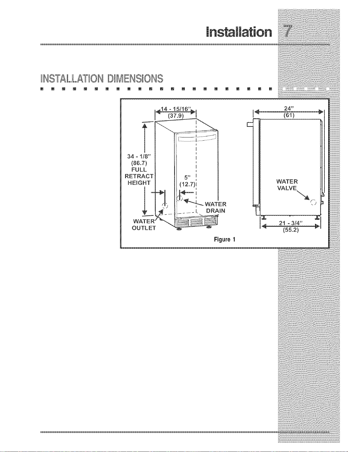
34 =!/8"
(86.7)
FULL
RETRACT
HEIGHT
(81)
WATER
VALVE
WATER
OUTLET
WATER
DRAIN
Figure 1
"_o
21 =3/4"
(55.2) v
THE£1N
[] [] [] [] [] [] [] [] [] [] [] [] [] [] [] [] [] [] [] [] [] []
Model E151M60E can be installed using a gravity drain or can use a factory installed
or equivalent drain pump.
Follow these guidelines when installing drain lines to prevent water from flowing
back into the ice maker storage bin and/or potentially flowing onto the floor causing
water damage:
GravityDrain
• Drain lines must have a 5/8 inch inside diameter.
• Drain lines must have a 1 inch drop per 48 inches of run (1/4 inch per foot) and
must not create traps.
• The floor drain must be large enough to accommodate drainage from all
drains.
• Insulate the bin drain line to prevent condensation.
raceMakersWith Factory mnstaHedDrain Pump
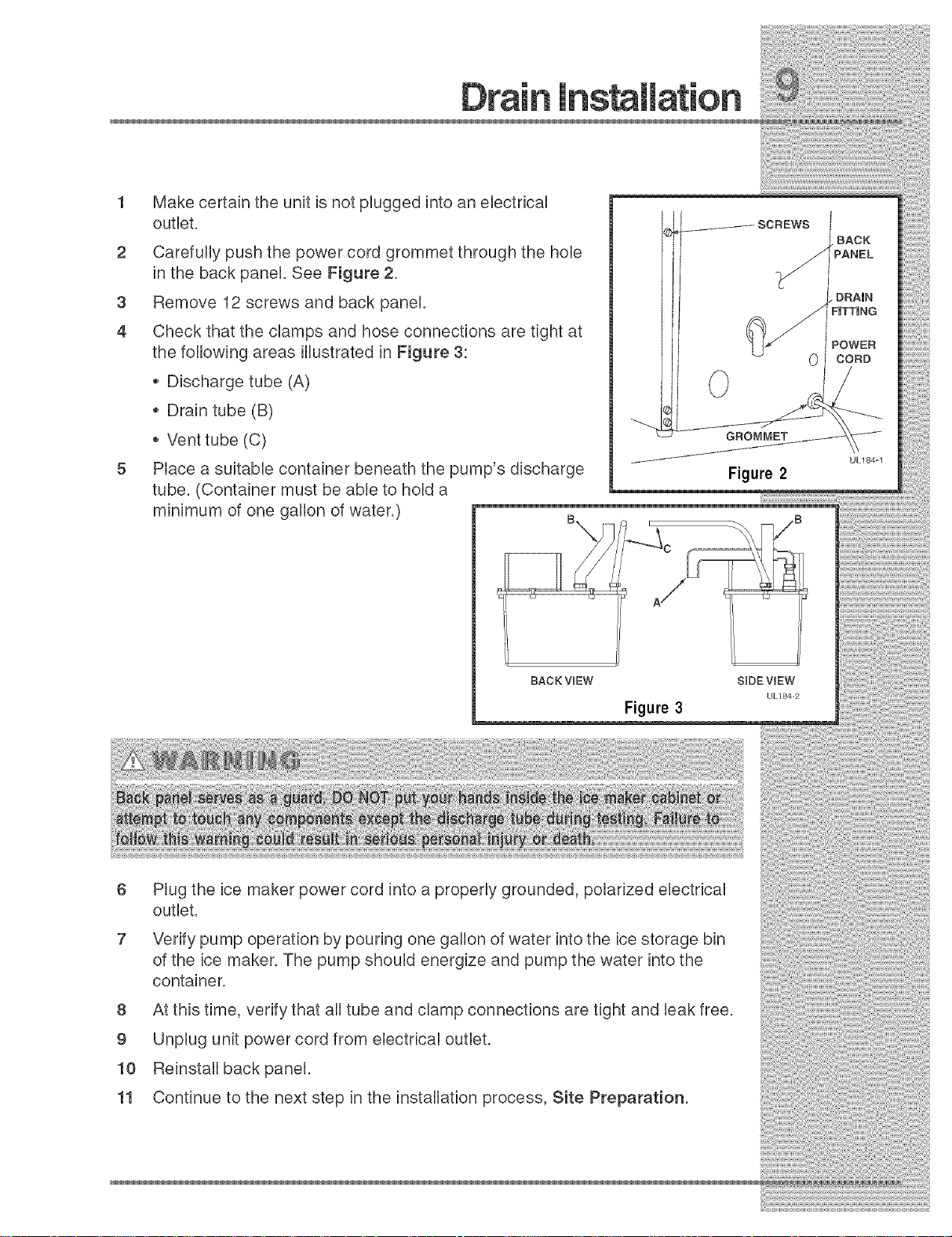
1 Make certain the unit is not plugged into an electrical
outlet.
2 Carefully push the power cord grommet through the hole
in the back panel. See Figure 2.
3 Remove 12 screws and back panel.
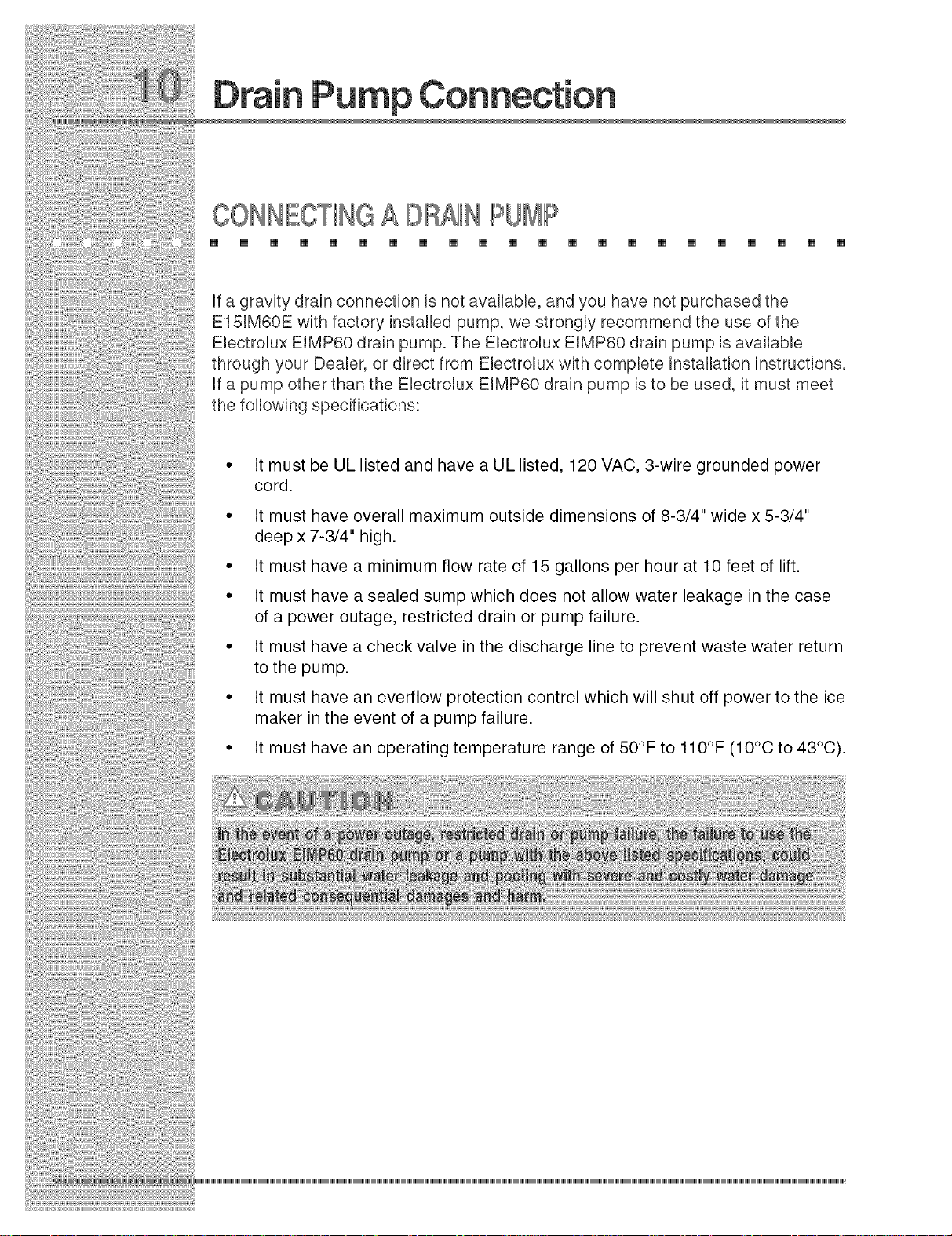
4 Check that the clamps and hose connections are tight at
the following areas illustrated in Figure 3:
Discharge tube (A)
,, Drain tube (B)
,, Vent tube (C)
5 Place a suitable container beneath the pump's discharge
tube. (Container must be able to hold a
minimum of one gallon of water.)
BACK
PANEL
DRAIN
FiTTiNG
POWER
CORD
GROMMET
UL184=1
Figure 2
BACK VIEW
Figure 3
Plug the ice maker power cord into a properly grounded, polarized electrical
outlet.
Verify pump operation by pouring one gallon of water into the ice storage bin
of the ice maker. The pump should energize and pump the water into the
container.
8 At this time, verify that all tube and clamp connections are tight and leak free.
9 Unplug unit power cord from electrical outlet.
10 Reinstall back panel.
11 Continue to the next step in the installation process, Site Preparation.
SDE ViEW
UL184_2
CONNE £ DR£11NPUMP
[] [] [] [] [] [] [] [] [] [] [] [] [] [] [] [] [] [] [] [] [] []
If a gravity drain connection is not availabb, and you have not purchased the
E15JM60E with factory installed pump, we strongly recommend the use of the
Eiectrolux EJMP60 drain pump. The Eiectrolux EIMP60 drain pump is available
through your Dealer, or direct from Ebctrolux with compbte installation instructions.
If a pump other than the Ebctrolux EIMP60 drain pump is to be used, it must meet
the following specifications:
• It must be UL listed and have a UL listed, 120 VAC, 3-wire grounded power
cord.
• It must have overall maximum outside dimensions of 8-3/4" wide x 5-3/4"
deep x 7-3/4" high.
• It must have a minimum flow rate of 15 gallons per hour at 10 feet of lift.
• It must have a sealed sump which does not allow water leakage in the case
of a power outage, restricted drain or pump failure.
• It must have a check valve in the discharge line to prevent waste water return
to the pump.
• It must have an overflow protection control which will shut off power to the ice
maker in the event of a pump failure.
° It must have an operating temperature range of 50°F to 110°F (10°C to 43°C).
IP PAB NGT SITE
[] [] [] [] m m [] [] [] [] m [] m [] [] [] [] m m m m []
1 Position the unit on a flat, level surface, capable of supporting the entire
weight of the unit. Remember that the unit will be significantly heavier once it
is fully loaded.
2 The surrounding air temperature must be at least 50°F (10°C) but must not
exceed 110°F (43°C).
3 The unit must not be located near heat-generating equipment or in direct
sunlight.
4
The unit must be located to allow clearance for water, drain and electrical
connections in the rear of the ice maker.
5
Connect the unit to a grounded and polarized 115 VAC, 60 Hz, 15 A circuit
(normal household current).
6
Avoid connecting the unit to a Ground Fault Interruptor (GFI). GFIs are prone to
nuisance tripping which will cause the unit to shut down. GFIs are generally not
used on circuits which power equipment that must run unattended for long
periods of time.
The unit must be installed according to your local codes and ordinances.

Figure4
6 Install and connect the water supply line. See
Connecting the Water Supply for installation
requirements.
7 Position the unit to allow free air flow through the
front grille (see Figure 6).
8 Wipe out inside of unit with a damp cloth.
0"
CLEARANCE
NEEDED
UL124A
WALL
2 * 3/4"
CLEARANCE
NEEDED
Figure 5
EXHAUST Figure 6 _NTAKE

Whenconnectingthewatersupply,followtheseguidelines:
ReviewthebcaUplumbingcodesbeforeyouinstaUltheunit.
Thewaterpressureshouldbebetween20 and120psi.
MakecertainaSHUT-OFFVALVEis
instaUledinthe 1/4inchwatersupplyHne.
Connectsufficienttubingtotheunittoallow
theunitto bemovedforcleaningand
servicing.However,makecertainthatthe
tubingisnotpinchedordamagedduring
installation.
Ebctroluxrecommendsthe useof copper
tubingforinstallation.
WATER
CONNECTmON
Figure 7
ULI03 CO
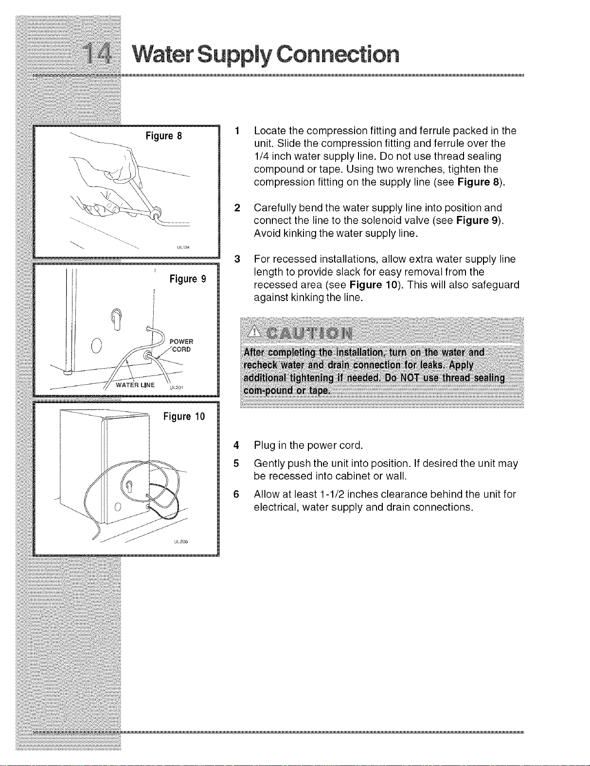
Figure8
Locate the compression fitting and ferrule packed in the
unit. Slide the compression fitting and ferrule over the
1/4 inch water supply line. Do not use thread sealing
compound or tape. Using two wrenches, tighten the
compression fitting on the supply line (see Figure 8).
\
Carefully bend the water supply line into position and
connect the line to the solenoid valve (see Figure 9).
Avoid kinking the water supply line.
% . UL134
For recessed installations, allow extra water supply line
F
Figure 9
length to provide slack for easy removal from the
recessed area (see Figure 10). This will also safeguard
against kinking the line.
POWER
WATER LiNE UL201
Figure 10
UL200
4 Plug in the power cord.
5 Gently push the unit into position. If desired the unit may
be recessed into cabinet or wall.
6 Allow at least 1-1/2 inches clearance behind the unit for
electrical, water supply and drain connections.

IILEV T UNiT
[] [] m m m m [] [] [] [] [] [] m [] [] [] [] m [] m m []
Use a ReveUto check the ReveUnessof the ice maker
from front to back and from side to side (see Figure
11).
tf the ice maker is not bveU, adjust the feet on the
corners of the unit as necessary (see Figure 12).
Check the bvelness after each adjustment and
repeat the previous steps until the unit is bveL
Figure 11
Figure 12

Figure 13
REVERSINGTHEBOOR(SOMEMO ILLS}
[] [] [] [] [] [] [] [] [] [] [] [] [] [] [] [] [] [] [] [] [] []
AH EbctroUux units may be bft or right hand opening. The door
opening is easily reversed by moving the hinge hard-ware to the
opposite side (see Figure 13).
To reverse the door:
1 Remove top hinge screw pin (7/64" AUUenwrench) from
cabinet (see Figure 14). Remove door by tilting forward
and Rifting off bottom hinge pin.
\
2 Remove pUastb screw plugs (3 top and 3 bottom) from
new hinge location (see Figure 15), and remove hinge pin
hole plug in top of door (see Figure 16). Do not discard.
J
Figure 14
SCREW
PLUGS
Figure 15
Figure 16
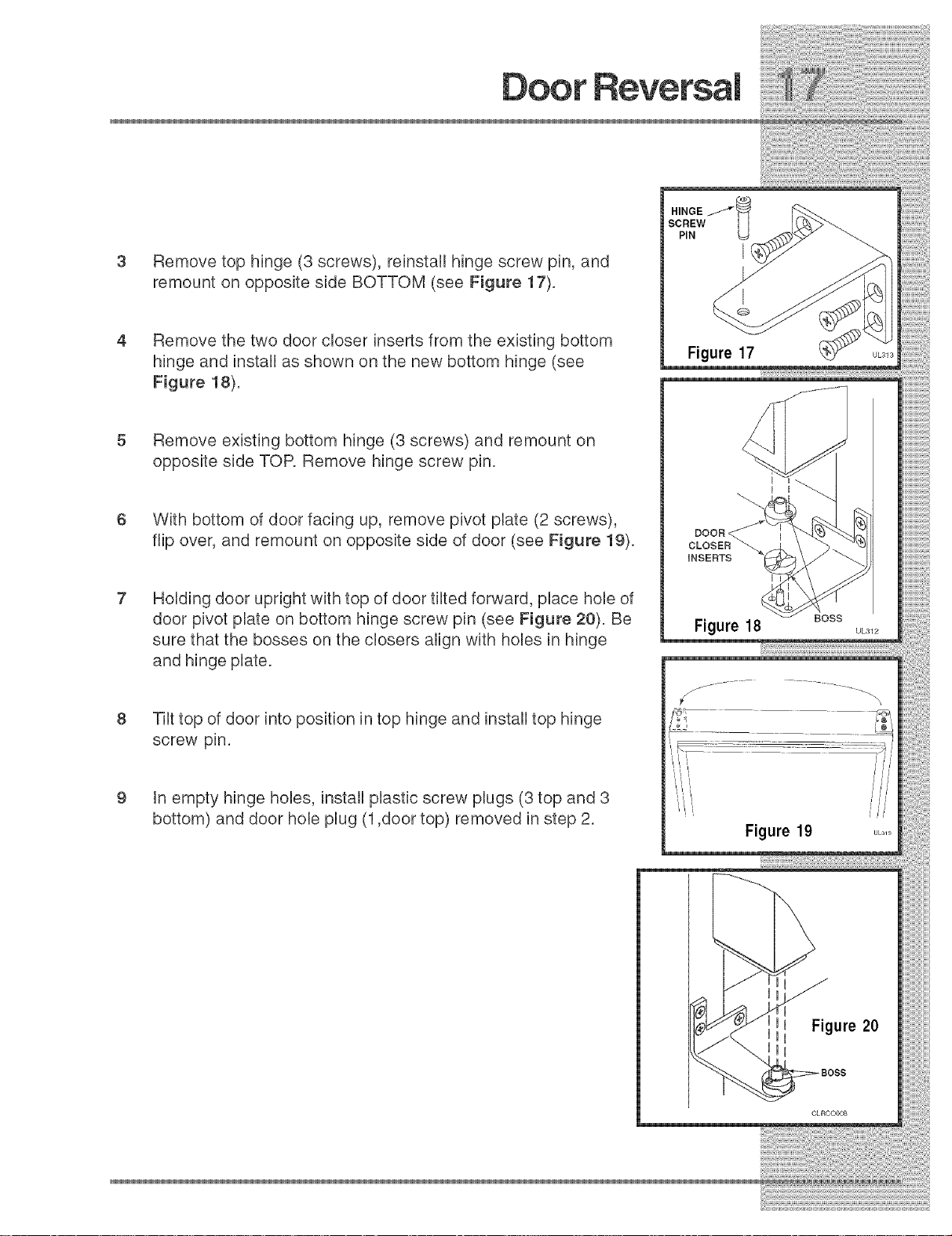
Remove top hinge (3 screws), reinstall hinge screw pin, and
remount on opposite side BOTTOM (see Figure 17).
HINGE _"_
SCREW I I
PiN _=_
i
Remove the two door cioser inserts from the existing bottom
hinge and instali as shown on the new bottom hinge (see
Figure 18).
Remove existing bottom hinge (3 screws) and remount on
opposite side TOP. Remove hinge screw pin.
With bottom of door facing up, remove pivot plate (2 screws),
flip over, and remount on opposite side of door (see Figure 19).
Holding door upright with top of door tiited forward, piace hole of
door pivot plate on bottom hinge screw pin (see Figure 20). Be
sure that the bosses on the closers align with holes in hinge
and hinge plate.
Tilt top of door into position in top hinge and instali top hinge
screw pin.
Figure 17
i
tn empty hinge holes, instali plastic screw plugs (3 top and 3
bottom) and door hole plug (1,door top) removed in step 2.
Figure 19
CLROO008
£DJUST NGTHEOB
[] [] [] [] [] [] [] [] [] [] [] [] [] [] [] [] [] [] [] [] [] []
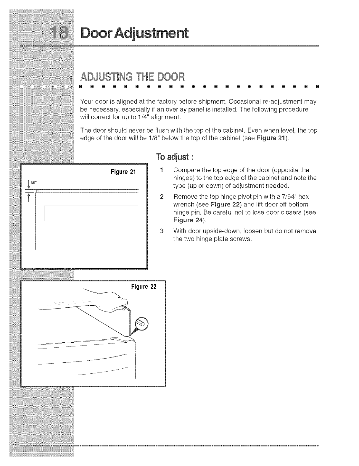
Your door is aligned at the factory before shipment. OccasionaU re=adjustment may
be necessary, especially if an overlay paneU is installed. The following procedure
will correct for up to 1/4" alignment.
The door shouUd never be flush with the top of the cabinet. Even when bveU, the top
edge of the door wiIRbe 1/8" below the top of the cabinet (see Figure 21).
Toadjust :
,_1/8"
t
Figure 21
Figure 22
1 Compare the top edge of the door (opposite the
hinges) to the top edge of the cabinet and note the
type (up or down) of adjustment needed.
2 Remove the top hinge pivot pin with a 7/64" hex
wrench (see Figure 22) and lift door off bottom
hinge pin. Be careful not to lose door closers (see
Figure 24).
3 With door upside-down, loosen but do not remove
the two hinge plate screws.
f

4 tf door edge opposite the Nnges needs to
move up, move plate toward outside of
door. tf door edge needs to move down,
move plate toward inside of door (see
Figure 23). Repeat until top edge of door is
parallel with top of cabinet and tighten
screws securely.
5 After adjustment is complete, remove the
door closers from the bottom hinge, clean
thoroughly and apply petroleum jelly to the
mating surfaces of the closers (see
Figure 24). Be sure that bosses on closers
align with holes in Mnge and hinge plate.
Mount door and install top hinge pivot pin.
MOUNTING _ IS NOTCH
HOLES _
RAISE _ LOWER
OUTSIDE OUTSIDE
DOOR EDGE DOOR EDGE
CLRCOOOla
DOOR
BOSS
Figure 24 UL3_2
£
[] [] [] [] [] [] [] [] [] [] [] [] [] [] [] [] [] [] [] [] [] []
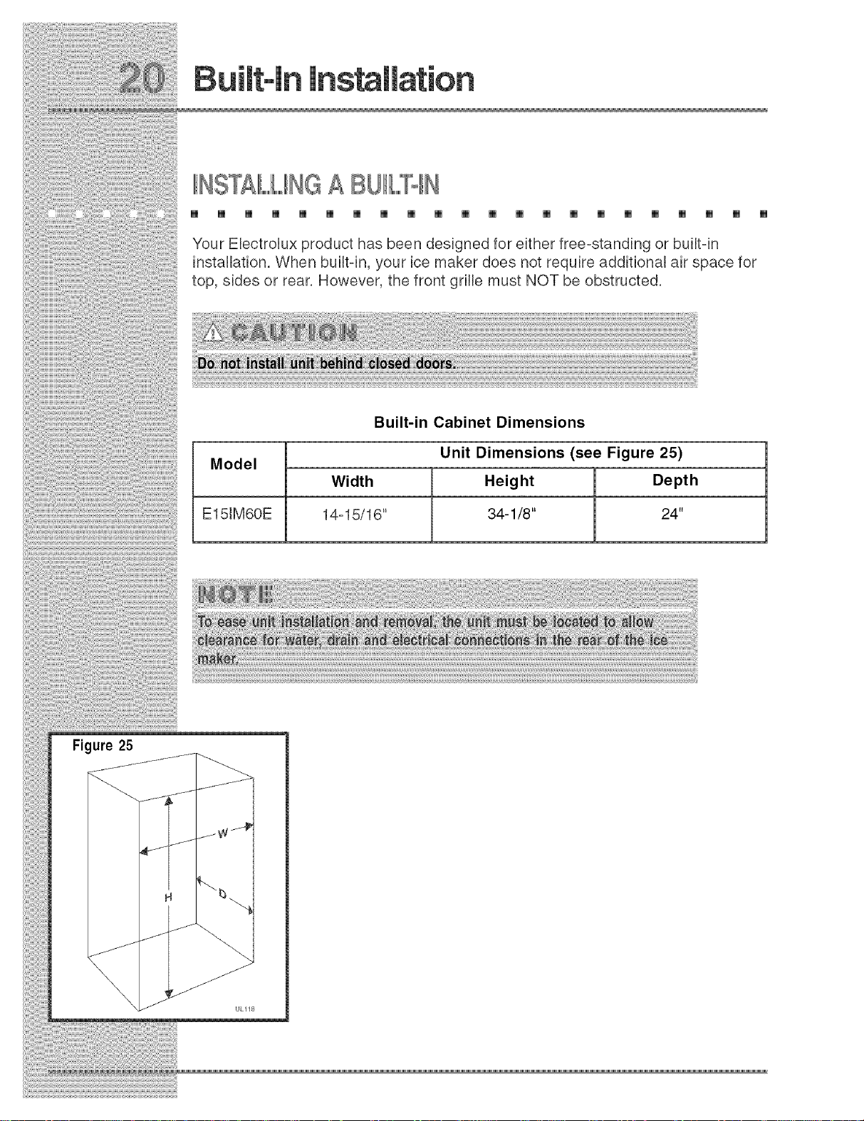
Your Electrolux product has been designed for either free-standing or built4n
installation. When built=in, your ice maker does not require additional air space for
top, sides or rear. However, the front grille must NOT be obstructed.
Built-in Cabinet Dimensions
Model
Width Height Depth
E151M60E 14=15/16" 34-1/8" 24"
Unit Dimensions (see Figure 25)
IINmAL,,,,,A
[] [] [] [] [] [] [] [] [] [] [] [] [] [] [] [] [] [] [] [] [] []
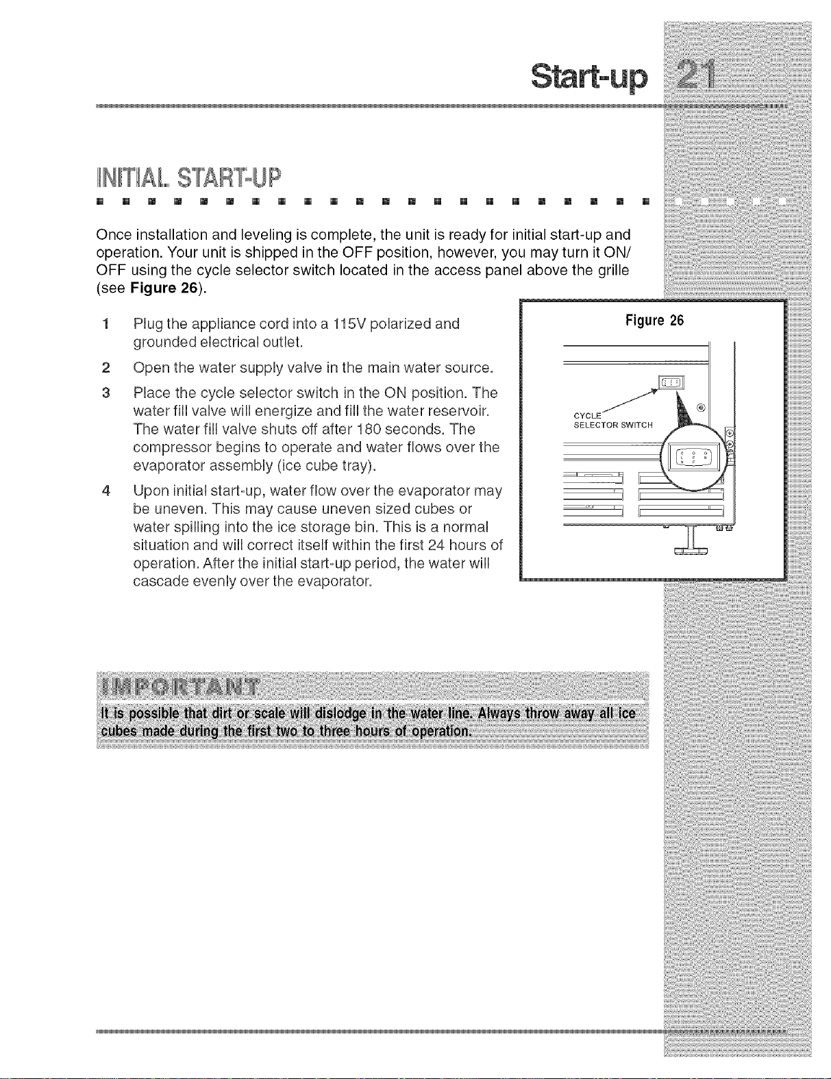
Once installation and leveling is complete, the unit is ready for initial start-up and
operation. Your unit is shipped in the OFF position, however, you may turn it ON/
OFF using the cycle selector switch located in the access panel above the grille
(see Figure 26).
1 PRugthe appliance cord into a 115V polarized and
grounded electrical outlet.
2 Open the water supply valve in the main water source.
3 PRace the cycle selector switch in the ON position. The
water fiIRvalve wifl energize and fill the water reservoir.
The water fill valve shuts off after 180 seconds. The
compressor begins to operate and water flows over the
evaporator assembly (ice cube tray).
4 Upon initial start=up, water flow over the evaporator may
be uneven. This may cause uneven sized cubes or
water spilfing into the ice storage bin. This is a normal
situation and will correct itself within the first 24 hours of
operation. After the initial start=up period, the water will
cascade evenly over the evaporator.
Figure 26
CYCLE
SELECTOR SWITCH
NORMAILOPER£T ON
[] [] [] [] [] [] [] [] [] [] [] [] [] [] [] [] [] [] [] [] [] []
The ice maker is designed to make clear ice from most water sources on a
consistent basis. Water is constantly circulated over the evaporator assembly. As
the water freezes, gravity causes any sediment to drop into the water trough and
not become imbedded in the ice. This gives a clearer ice cube with a low mineral
content. When the ice reaches the desired thickness, it falls off the evaporator and
into the storage bin. The cycle is then repeated. When the level of ice reaches the
top of the storage bin the unit shuts off. As the ice level in the bin drops the unit will
automatically restart to keep the bin full. Your unit's ice production rate may vary
depending on many considerations. Ambient air temperatures, water
temperatures, condenser cleanliness and ice-maker cleanliness are all
contributing factors to how quickly the unit produces ice. Certain sounds are
normal during the unit's operation. You may hear the compressor or fan motor, the
water valve, the water circulation pump or ice dropping into the ice storage bin.
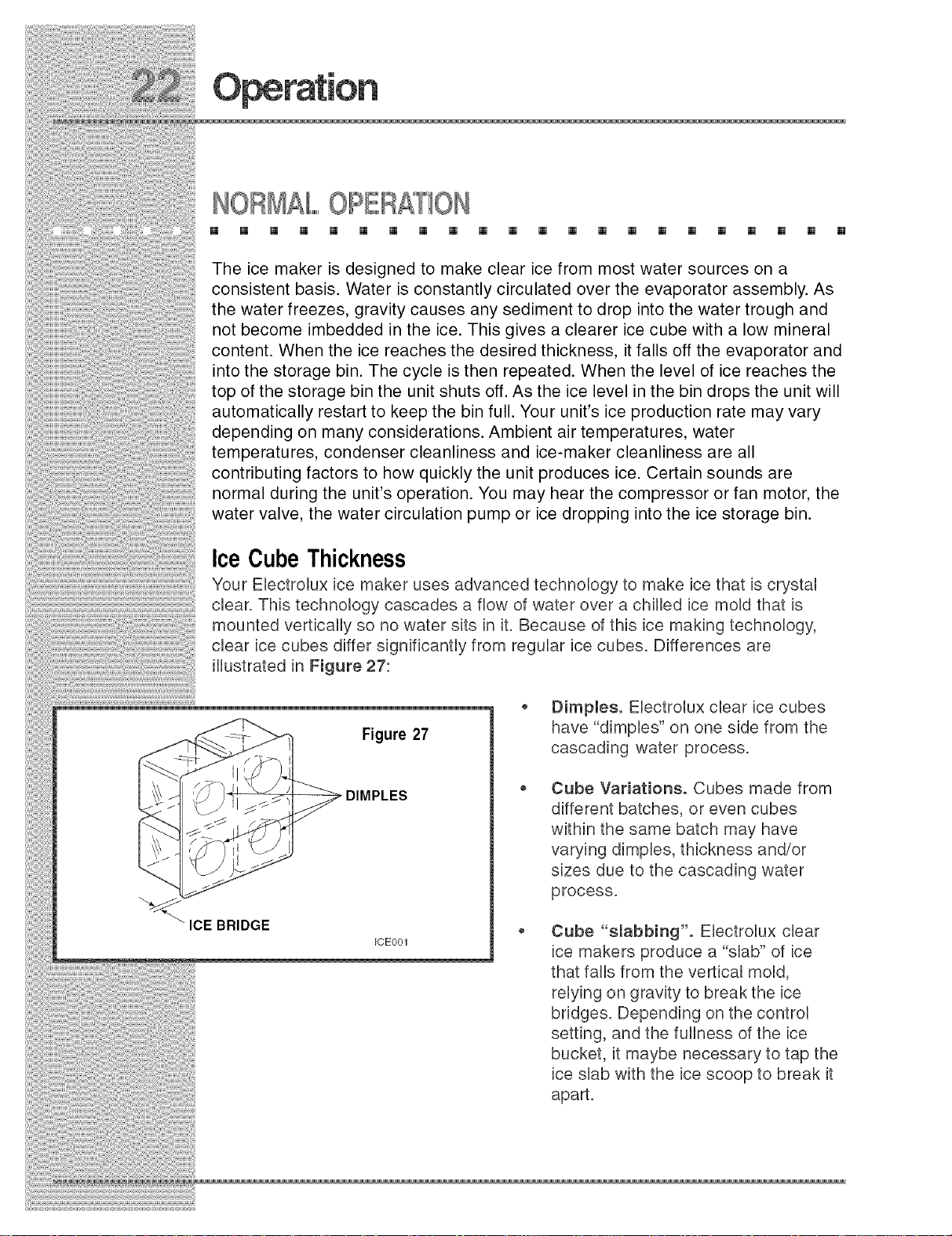
Ice Cube Thickness
Your Ebctrolux ice maker uses advanced technology to make ice that is crystal
clear. This technology cascades a flow of water over a chilled ice mold that is
mounted vertically so no water sits in it. Because of this ice making technology,
clear ice cubes differ significantly from regular ice cubes. Differences are
illustrated in Figure 27:
Figure 27
ICE001
Dimpieso Electrolux clear ice cubes
have "dimples" on one side from the
cascading water process.
Cube Variations. Cubes made from
different batches, or even cubes
within the same batch may have
varying dimples, thickness and/or
sizes due to the cascading water
process.
Cube "slabbing'. Ebctrolux clear
ice makers produce a "slab" of ice
that falls from the vertical mold,
relying on gravity to break the ice
bridges. Depending on the control
setting, and the fullness of the ice
bucket, it maybe necessary to tap the
ice slab with the ice scoop to break it
apart.

liCEDISPENSEROPERATION& CARE
[] [] [] [] [] [] [] [] [] [] [] [] [] [] [] [] [] [] [] [] [] []
The be cube thbkness control is factory set for best overall performance. The
factory setting is designed to
maintain an be bridge of
approximately 1/16" to 1/8" under
normal conditions resulting in a
dimple of approximately 1/4" to 1/2"
in depth (see Figure 28). A fuller
cube with less of a dimple results in
a thicker ice bridge. As the ice bridge
becomes thicker, the tendency for
the cubes to stay together as a slab
increases. A bridge thicker than 1/8"
may cause cubes to over-fill the ice
bucket.
GOOD
Figure 28
1/16" TO 1/8"
ICE BRIDGE
DIMPLE _\ LITTLE OR //
TOO DEEP \\ NO DIMPLE /
BRIDGE BRIDGE
TOO THIN TOO THICK
BAD
To adjust:
1 Disconnect power to the unit.
2 Remove the screws securing the
front access panel (see Figure 29).
Figure 29
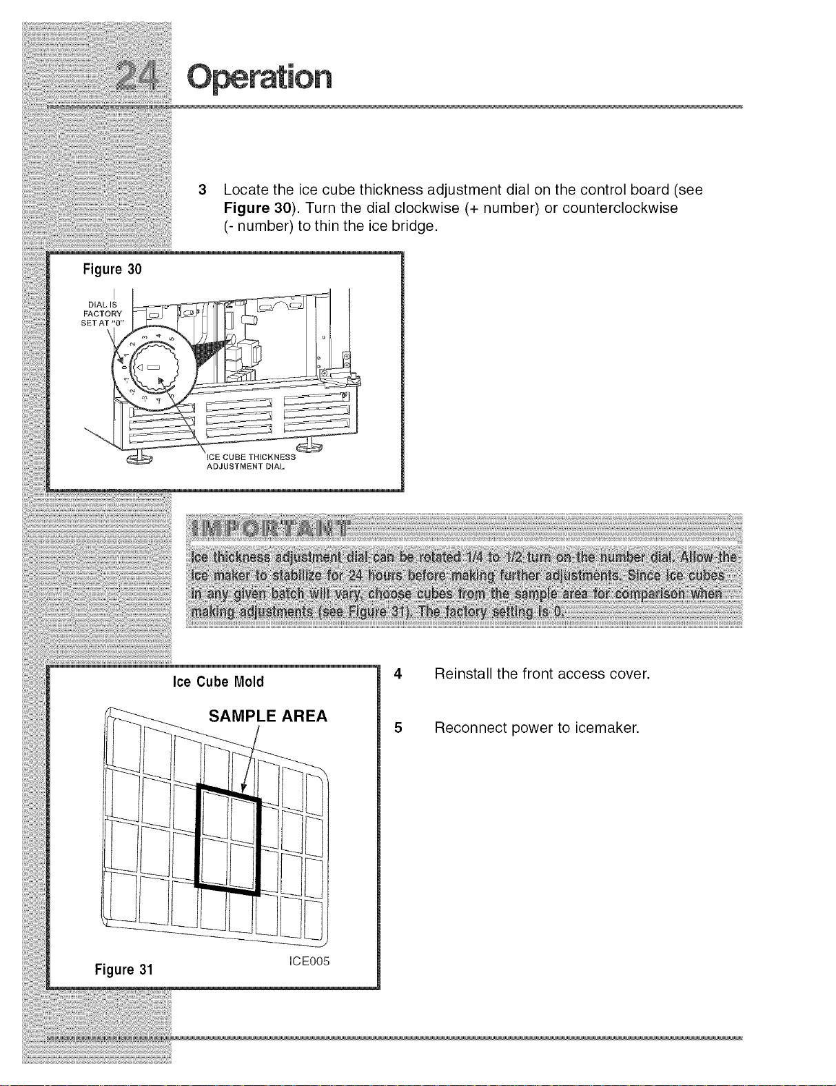
Figure 30
I
DIAL IS
FACTORY
SET AT"O"
3 Locate the ice cube thickness adjustment dial on the control board (see
Figure 30). Turn the dial clockwise (+ number) or counterclockwise
(- number) to thin the ice bridge.
ICE CUBE THICKNESS
ADJUSTMENT DIAL
_!i !!_i_i!i!_i_i!ii!_i_!_!_i_i!!i!_i!;_i_i!_!i!i!i_!_!i_!_!!i_!_!i_!_i!_!_!i_!_!i!_i_!_!i_i_i!i_i!_!_i_ii_i!_ii_!_i_i!_i_!_i_i!iiiii!iiii!iiiii!iiii!iiiii!iiii!iiiii!iiii!iiiii!iiii!iiiii!iiii!iiiii!iiii!iiiiiii!iiil;ii!iiii!iii!iiiiiiiiiii!iiiili!ii!iii!i!ii!i
Figure 31
Ice Cube Mold
SAMPLE AREA
Reinstall the front access cover.
Reconnect power to icemaker.
ICEO05
SPECiAl,,,,,,,,,,CONSDERATIONS
[] [] [] [] [] [] [] [] [] [] [] [] [] [] [] [] [] [] [] [] [] []
For best performance, keep the unit out of direct sunlight.
Turn the unit OFF and dispose of any be cubes if the unit will not be used for
5 days or more. Prop door open to allow for air circulation and prevent mold
and mildew.
tf the ambbnt temperature is expected to drop below 45°F (7°C), drain all
water from the unit to prevent freezing damage not covered by the warranty.
High ambient temperatures, 110°F (43°C) or higher, may reduce the unit's
ability to reach low temperatures and may also reduce the ice production
rate.
MAINTAININGANDCLEANIINGYOUR CEMAKEB
[] [] [] [] [] [] [] [] [] [] [] [] [] [] [] [] [] [] [] [] [] []
Periodic cleaning and proper maintenance will ensure efficiency, top performance,
and long life. The maintenance intervals listed are based on normal conditions. You
may want to shorten the intervals if you have pets or other special considerations.
ExteriorCleaningoAs Required
The door, grille and cabinet may be cleaned with a mild detergent and warm water
solution. Do not use solvent based or abrasive cleaners.
Use a soft sponge and rinse with clean water. Wipe with a soft, clean towel to
prevent water spotting.
StainlessSteel Models
• Stainbss steel models may dbcolor when exposed to chlorine gas, pool
chembab, salt water or cleaners with bleach.
• Keep your stainless unit looking new by cleaning with a high quality, alPin-one
stainless steel cleaner/polish on a monthly bash. Frequent cleaning will
remove surface contamination that could lead to rust. Some installations will
require cleaning on a weekly basis.

®
DO NOT CLEAN WITH STEEL WOOL PADS.
o
DO NOT USE CLEANERS THATARE NOT SPECIFICALLY INTENDED FOR
STAINLESS STEEL (this includes glass, tile and counter cleansers).
tf any surface discolors or rusting appears, clean it quickly with Bon-Ami or
Barkeepers Friend Cleanser and a non-abrasive cloth. Always clean in the
direction of the grain. Always finish this process with a high quality, aINn-one
stainless steel cleaner/polish to prevent further problems.
,, USE OF ABRASIVE PADS SUCH AS SCOTCHBRFE WiLL CAUSE THE
GRAINING tN THE STAINLESS TO BECOME BLURRED.
Rust that is allowed to linger can penetrate into the surface of the stainless
steel and become impossible to remove.
mnteriorCleaningoAs Required
1 Disconnect power to the ice maker.
2 Open the door and remove any ice from the storage bin.
3 Wipe down the interior and storage bin with a solution of non-abrasive mild
soap or detergent and warm water. Rinse with clean water.
4 Sanitize the bin with a solution of 1 tablespoon of bleach in 1 gallon of warm
water. Rinse thoroughly with clean water.
5 Check that all drain connections are in place.
6 Reconnect power to the unit.

CondenserCleaning-- Every3 Months
To maintain operational efficiency, clean the condenser every three months
(depending on environmental conditions, more or less frequent cleaning may be
necessary).
To remove and replace the grille for access to
the condenser fins follow this procedure (see
Figure 32):
1 Remove the screws at each end of the
grille.
2 Remove the grille.
Figure 32
CONDENSER
Clean the condenser coil using a brush with a "combing" action, or a vacuum
cleaner. Do not touch the condenser coil.
4
Position the grille to align the screw holes with the cabinet.
5
Insert the grille screws and tighten. Do not over tighten.

Sdf Cleaning-- Every6 Months
To maintain operational efficiency, clean the unit every six months (depending on
water conditions more or lees frequent cleaning may be necessary), if the ice
maker requires more frequent cleaning, consult a qualified plumber to test the
water quality and recommend appropriate treatment.
Ice machine cleaner is used to remove lime scale and other mineral deposits.
Refer to the following steps for mineral deposit removal.
1 Set the cycle selector switch to OFF and allow the ice
to melt off of the evaporator.
J / F
2 Remove all ice from the storage bin.
3 Remove inside front cover (see Figure 33).
FRONT
COVER
Figure 33

Removetheoverflowtubebyliftingit upwhileusinga
slightbackandforthmotionto loosenitfromthe drain
hole(seeFigure34).Thewaterinthereservoirwillflow
downthe drain.
Replacetheoverflowtubeafterallofthewaterhas
drainedfromthe reservoir.
6
MovethecycleselectorswitchtotheCLNposition.
7
Whenwaterbeginstoflowoverthe evaporator
(approximately3 minutes),addonepackageof Electrolux
ice MacNneCleanertothewaterreservoir.
8
Reinstallinsidefrontcover.
9
Whentheself-cleaningprocessstops(approximately45
minutes)it maybedesirableto cleanthestoragebinat
tMstime (seeInterior Cleaning).
10
MovethecycleselectorswitchtotheiCE/ONpositiontoresumeice
production.
InletScreenCleaning-- EveryYear
The solenoid valve inlet screen must be cleaned at least once each year as
follows:
Figure 34
UL209a
1 Shut off the water at the water supply valve.
Figure 35
2 Pull the unit out to access the back panel (see
Figure 35).
3 Disconnect electrical power to the unit.
4 Disconnect the entire hose connector from the water
solenoid valve (see Figure 35).
5 Use a tooth brush to clean sediment from the inlet
screen. DO NOT remove the screen.
Re=connect the water supply fine to the water solenoid
valve. Tighten connector securely. Open the water
supply valve and check for leakage at the water
connection. Make sure the water supply line is not
kinked.
7 Reconnect power to the unit before reqnstalling..
Make sure the drain system is working properly and the drain hose is not
pinched or kinked. Pour one gallon of cool, fresh water into the ice bin. The
water should drain freely.. If your ice maker is equipped with a drain pump, the
pump should drain the ice bin.
WATER
CONNECTmON
UL103 CO

DBABNBNGIB:'":'ORNON@SE
[] [] [] [] [] [] [] [] [] [] [] [] [] [] [] [] [] [] [] []
If the unit is to be stored, moved or not used for extended periods, it will be
necessary to drain the system of water.
1 Disconnect power from the unit.
2 Remove ice from the storage bin.
3 Shut off water supply at the main water source.
4 Disconnect the inlet and outlet lines to the water valve and allow them to
drain.
[] []
5
Reconnect inlet and outlet lines to the water valve.
6
Replace back panel.
7
Drain water from the water trough and drain line by removing the overflow
tube (see Figure 34).
8
Clean the ice maker and storage bin before next use.
9
Prop door open to allow for air circulation and prevent mold and mildew.

BEFOREYOUCALL FORSERVICE
[] [] [] [] [] [] [] [] [] [] [] [] [] [] [] [] [] [] [] [] [] []
tf the unit appears to be malfunctioning, read through Normal Operation first. If the
problem persbts, check the Troubleshooting Guide. Locate the problem in the
guide and refer to the cause and its remedy before calling for servbe. The problem
could be sometNng very simpb whbh can be solved without a servbe call.
Troubleshooting - What to check when problems
Occur
Problem PossibleCause Remedy
Unitdoesnotoperate.
Unitrunsbutnoiceisproduced. • Nowaterbeingsuppliedtothe • Checktoseethatwaterisconnectedandturned
Unitrunsbutproducesverylittleice. • Dirtycondensercoils.
Iceis slowto releaseordoesnot
releasefromtheevaporator.
• No electricalpowertotheunit.
• Cycleselectorswitchset
improperly.
• Low airtemperaturearoundunit.
unit. ontothe unit.
• Highairtemperaturearoundunit.
• Scaleandmineralbuildupinunit.
• Inadequateairflowatthefrontof
theunit.
• Ice-makingsystemisdirty. • Rununitthroughautomaticcleancycle.See
• Unitis netlevel. • SeeLevelingthe Unit.
• Low airtemperaturearoundthe unit. • Surroundingairtemperaturemustbeatleast50°F
• Makesurepowercordispluggedin. Checkfor
blownfuseortrippedcircuitbreaker.
• MakesurecycleselectorswitchissettoICE/ON.
• Surroundingairtemperaturemustbeatleast
45°F(7°C).
• Cleanthe condenser.SeeMaintenance.
• Surroundingair temperatureof ever90°F(32°C).
Lowiceproductionathightemperaturesis
normal.
• Cleanunit.SeeMaintenance.
• Removeitemsblockingairflow.
Maintenance.
(t0°C).
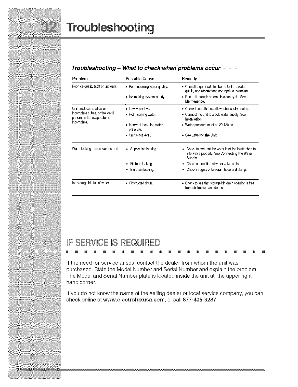
Troubleshooting - What to check when problems occur
Problem
Pooricequality(softorunclear).
Unitproducesshallowor
incompletecubes,orthe icefill
pattemontheevaporatoris
incomplete.
Waterleakingfromundertheunit. • Supplylineleaking.
Icestoragebinfullofwater. • Obstructeddrain. • Checktoseethatstoragebindrainopeningisfree
PossibleCause
• Poorincomingwaterquality.
• Ice-makingsystemisdirty.
• Lowwater level.
• Hot incomingwater.
• Incorrectincomingwater
pressure.
• Unitisnetlevel.
• Filltube leaking.
• Bindrainleaking.
Remedy
• Consultaqualifiedplumbertotestthewater
qualityandrecommendappropriatetreatment.
• Rununitthreughautomaticcleancycle.See
Maintenance.
• Checktoseethatoverflowtube isfullyseated.
• Connecttheunittoacoldwatersupply.See
Installation.
• Waterpressuremustbe20-120psi.
• SeeLevelingtheUnit.
• Checktoseethatthewaterinletlineis attachedto
inletvalveproperly.SeeConnectingtheWater
Supply.
• Checkconnectionatwatervalveoutlet.
• Checkintegrityofbindrainhoseandclamp.
fromobstructionand debris.
IIFSERVICEIISREQUR
[] [] [] [] [] [] [] [] [] [] [] [] [] [] [] [] [] [] [] [] [] []
If the need for servbe arbes, contact the dealer from whom the unit was
purchased. State the Model Number and Serial Number and explain the problem.
The Model and Serial Number plate is located inside the unit at the upper right
hand corner.
If you do not know the name of the selling dealer or local service company, you can
check online at www.emectromuxusa.com, or call 877-435-3287.
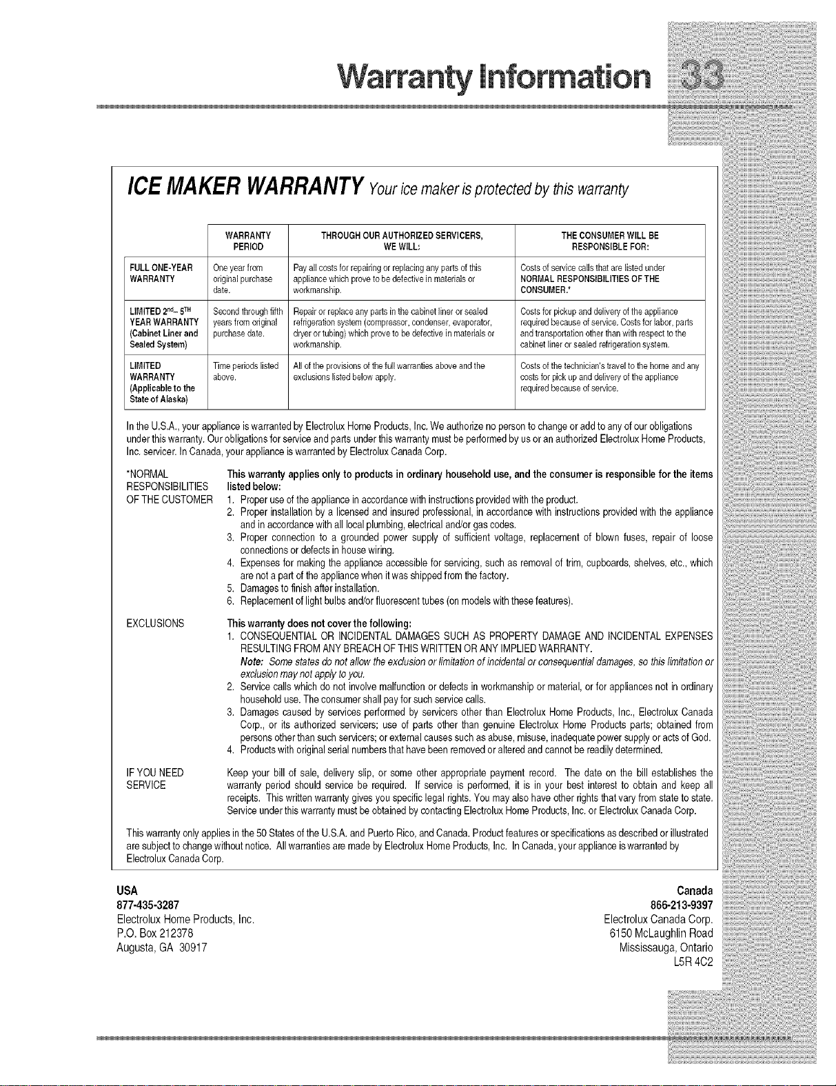
ICEMAKERWARRANTYYourice makerisprotectedby this warranty
WARRANTY THROUGHOURAUTHORIZEDSERVICERS, THECONSUMERWILLBE
PERIOD WEWILL: RESPONSIBLEFOR:
FULLONE-YEAR Oneyearfrom Payallcostsforrepairingorreplacinganypartsofthis Costsofservicecallsthatarelistedunder
WARRANTY originalpurchase appliancewhichprovetobedefectivein materialsor NORMALRESPONSIBILITIESOFTHE
LIMITED2"d-5TM Secondthroughfifth Repairorreplaceanypartsinthecabinetlinerorsealed Costsforpickupanddeliveryoftheappliance
YEARWARRANTY yearsfromoriginal refrigerationsystem(compressor,condenser,evaporator, requiredbecauseofservice.Costsforlabor,parts
(CabinetLinerand purchasedate. dryerortubing)whichproveto bedefectiveinmaterialsor andtransportationotherthanwithrespecttothe
SealedSystem) workmanship, cabinetlinerorsealedrefrigerationsystem.
LIMITED Timeperiodslisted Alloftheprovisionsofthefullwarrantiesaboveandthe Costsofthetechnician'straveltothehomeandany
WARRANTY above, exclusionslistedbelowapply, costsforpickupanddeliveryof theappliance
(Applicableto the requiredbecauseofservice.
Stateof Alaska)
Inthe U.S.A.,yourapplianceiswarrantedbyElectroluxHomeProducts,Inc.We authorizenopersonto changeoradd to anyofourobligations
underthiswarranty.Our obligationsfor serviceandpartsunderthiswarrantymustbe performedbyusoran authorizedElectroluxHomeProducts,
Inc.servicer.InCanada,yourapplianceiswarrantedbyElectroluxCanadaCorp.
*NORMAL
RESPONSIBILITIES
OFTHEOUSTOMER
EXCLUSIONS
IFYOUNEED
SERVICE
Thiswarrantyonlyappliesinthe50Statesof the U.S.A.andPuertoRico,andCanada.Productfeaturesor specificationsasdescribedor illustrated
are subjectto changewithoutnotice. All warrantiesaremadeby ElectroluxHomeProducts,Inc. InCanada,yourapplianceiswarrantedby
ElectroluxCanadaCorp.
date. workmanship. CONSUMER,*
Thiswarranty appliesonlyto productsin ordinaryhousehold use, andthe consumeris responsiblefor the items
listedbelow:
1. Properuseoftheappliancein accordancewith instructionsprovidedwiththeproduct.
2. Properinstallationby a licensedand insuredprofessional,inaccordancewithinstructionsprovidedwiththeappliance
andin accordancewith all localplumbing,electricaland/orgascodes.
3. Proper connectionto a groundedpowersupply d sufficientvoltage, replacementof blown fuses, repairof loose
connectionsor defectsinhousewiring.
4. Expensesfor makingtheapplianceaccessiblefor servicing,such as removalof trim,cupboards,shelves,etc.,which
arenotapartd theappliancewhenit wasshippedfromthefactory.
5. Damagesto finishafterinstallation.
6. Replacementof light bulbsand/orfluorescenttubes (onmodelswiththesefeatures).
Thiswarrantydoesnot coverthefollowing:
1. CONSEQUENTIALOR INCIDENTALDAMAGESSUCH AS PROPERTYDAMAGEAND INCIDENTALEXPENSES
RESULTINGFROMANYBREACHOF THISWRITTENORANY IMPLIEDWARRANTY.
Note: Somestatesdonot allowthe exclusionor limitationof incidentalor consequentialdamages,so this limitationor
exclusionmaynot applytoyou.
2. Servicecallswhichdo not involvemalfunctionor defectsin workmanshipor material,orfor appliancesnot inordinary
householduse.Theconsumershallpayforsuch servicecalls.
3. Damagescausedby services performedby servicersotherthan ElectroluxHomeProducts,Inc.,ElectroluxCanada
Corp.,or its authorizedservicers;use of parts otherthan genuineElectroluxHomeProductsparts; obtainedfrom
personsotherthan suchservicers;orexternalcausessuchasabuse,misuse,inadequatepowersupplyoractsofGod.
4. Productswithoriginalserialnumbersthathavebeenremovedor alteredandcannotbereadilydetermined.
Keepyour bill of sale, deliveryslip, or some otherappropriatepayment record. The date on the bill establishesthe
warrantyperiod should service be required. If service is performed,it is in your best interest to obtainand keep all
receipts.This writtenwarrantygivesyouspecificlegalrights.Youmayalsohaveother rightsthat varyfrom stateto state.
Serviceunderthis warrantymustbeobtainedby contactingElectroluxHomeProducts,Inc.or ElectroluxCanadaCorp.
USA Canada
877-435-3287 866-213-9397
ElectroluxHomeProducts,Inc. ElectroluxCanadaCorp.
P.O.Box212378 6150McLaughlinRoad
Augusta,GA 30917 Mississauga,Ontario
L5R4C2


 Loading...