

Electrolux CEI30EF3JSA, CEI30EF5GBB, CEI30EF5GSB, CEI30EF5GSC, CEI30EF5GSD Installation Guide
...Page 1
Installation Instructions
7() _ F_ec_Sta_,_di_,_!:__i/_:_ct_ic Ra__:_:_
Instructions d'installation
Electrolux
Page 2
INSTALLATION AND SERVICE MUST BE PERFORMED BY A QUALIFIED INSTALLER.
IMPORTANT: SAVE FOR LOCAL ELECTRICAL iNSPECTOR'S USE.
READ AND SAVE THESE INSTRUCTIONS FOR FUTURE REFERENCE.
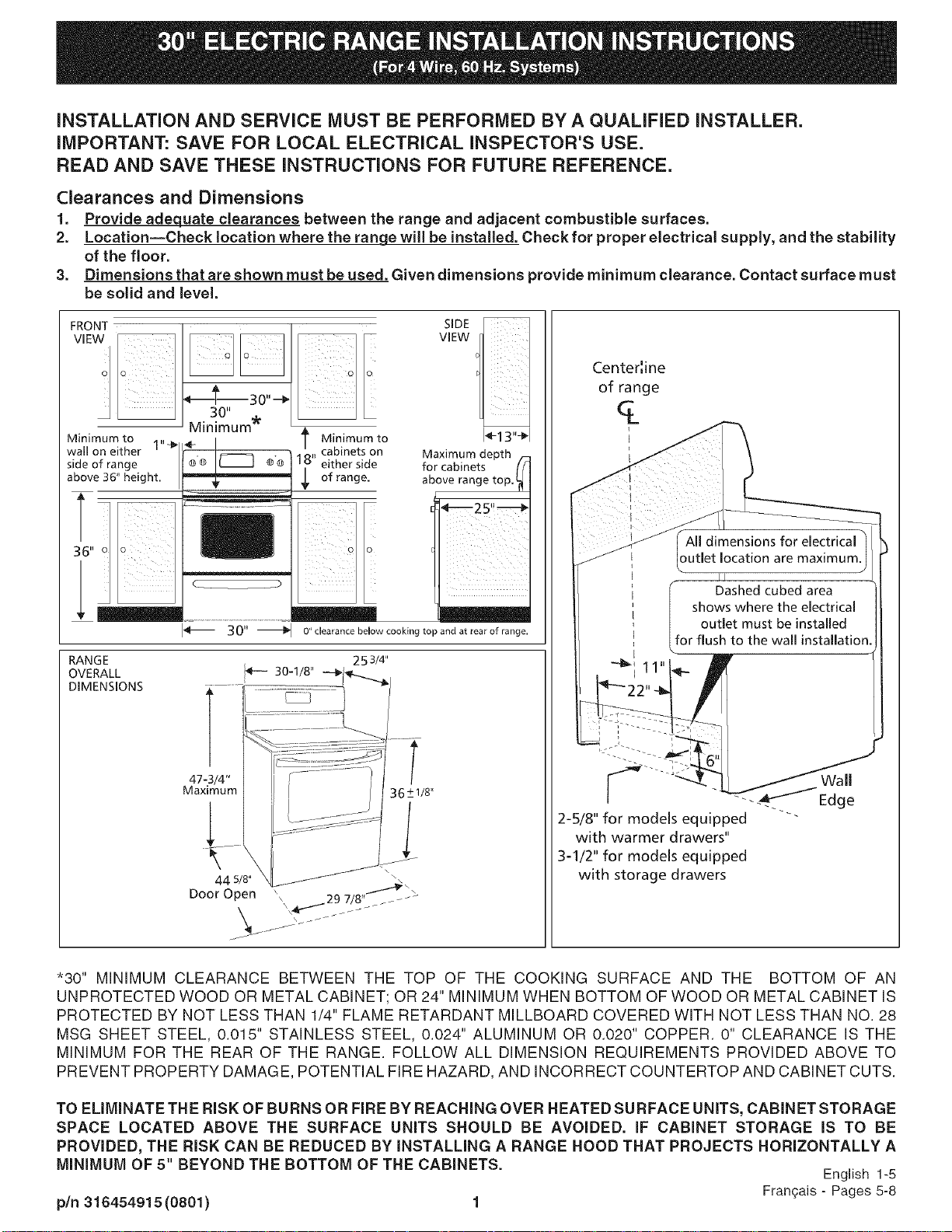
Clearances and Dimensions
1. Provide adequate clearances between the range and adjacent combustible surfaces.
2. Location--Check location where the range will be installed. Check for proper electrical supply, and the stability
of the floor.
3. Dimensions that are shown must be used. Given dimensions provide minimum clearance. Contact surface must
be solid and level.
FRONT
Minimum to
wall on either 1"-_
side of range
above 36" height.
RANGE
OVERALL
DIMENSIONS
_ t Minimum to
._.........._............................................._ _ of range.
30" _ O" clearance below cooking top and at rear of range.
' 18" cabinets on
either side
253/4"
SIDE
VIEW
I_-13"_1
Maximum depth f-
for cabinets ((
above range top.
_e---25,_
Center',ine
of range
q_
i
i
I .........
t
I
I outlet location are maximum.
Dashed cubed area
i sh°u_lSetWhe:t tt:heeeltc[IreC;I
I I :or flush to the wall installation.
I -11.1
2-5/8" for models equipped
with warmer drawers"
3-1/2" for models equipped
with storage drawers
*30" MINIMUM CLEARANCE BETWEEN THE TOP OF THE COOKING SURFACE AND THE BOTTOM OF AN
UNPROTECTED WOOD OR METAL CABINET; OR 24" MINIMUM WHEN BOTTOM OF WOOD OR METAL CABINET IS
PROTECTED BY NOT LESS THAN 1/4" FLAME RETARDANT MILLBOARD COVERED WITH NOT LESS THAN NO. 28
MSG SHEET STEEL, 0.015" STAINLESS STEEL, 0.024" ALUMINUM OR 0.020" COPPER. 0" CLEARANCE IS THE
MINIMUM FOR THE REAR OF THE RANGE. FOLLOW ALL DIMENSION REOUIREMENTS PROVIDED ABOVE TO
PREVENT PROPERTY DAMAGE, POTENTIAL FIRE HAZARD, AND INCORRECT COUNTERTOP AND CABINET CUTS.
TO ELIMINATE TH E RISK OF BURNS OR FIRE BY REACHING OVER HEATED SURFACE UNITS, CABINET STORAGE
SPACE LOCATED ABOVE THE SURFACE UNITS SHOULD BE AVOIDED. IF CABINET STORAGE IS TO BE
PROVIDED, THE RISK CAN BE REDUCED BY INSTALLING A RANGE HOOD THAT PROJECTS HORIZONTALLY A
MINIMUM OF 5" BEYOND THE BOTTOM OF THE CABINETS. English 1-5
pin 316454915 (0801) 1 Fran_ais - Pages 5-8
Page 3
iMPORTANT SAFETY
iNSTRUCTiONS
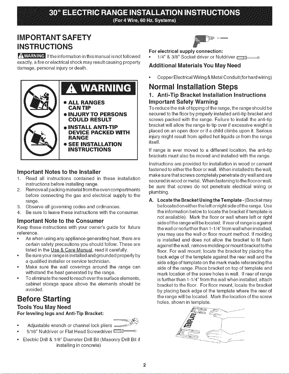
If the informationin this manual is not followed
exactly, afi re or electrical shock may result causing property
damage, personal injury or death.
• ALL RANGES
CAN TIP
• INJURYTO PERSONS
COULD RESULT
o INSTALL ANTI=TIP
DEVICE PACKED WiTH
RANGE
• SEE iNSTALLATiON
iNSTRUCTIONS
Important Notes to the Installer
1. Read all instructions contained in these installation
instructions before installing range.
2. Removeall packing material from the oven compartments
before connecting the gas and electrical supply to the
range.
3. Observe all governing codes and ordinances.
4. Be sure to leave these instructions with the consumer.
Important Note to the Consumer
Keep these instructions with your owner's guide for future
reference.
• As when using any appliance generating heat, there are
certain safety precautions you should follow. These are
listed in the Use & Care Manual, read it carefully.
• Be sure your range isinstalledand grounded properly by
a qualified installer or service technician.
• Make sure the wall coverings around the range can
withstand the heat generated by the range.
• To eliminate the need to reach over thesurface elements,
cabinet storage space above the elements should be
avoided.
Before Starting
Tools You May Need
For leveling legs and Anti-Tip Bracket:
For electrical supply connection:
• 1/4" & 3/8" Socket driver or Nutdriver
Additional Materials You May Need
Copper Electrical Wiring & Metal Conduit (for hard wiring)
Normal installation Steps
1. Anti-Tip Bracket Installation Instructions
Important Safety Warning
To reduce the risk of tipping of the range, the range should be
secured to the floor by properly installedanti-tip bracket and
screws packed with the range. Failure to install the anti-tip
bracket will allow the range to tip over if excessive weight is
placed on an open door or if a child climbs upon it. Serious
injury might result from spilled hot liquids or from the range
itself.
If range is ever moved to a different location, the anti-tip
brackets must also be moved and installed with the range.
instructions are provided for installation in wood or cement
fastened to either the floor or wall. When installed to the wall,
make sure that screws completely penetrate dry wall and are
secured inwood or metal. When fastening to the fiooror wall,
be sure that screws do not penetrate electrical wiring or
plumbing.
A. Locate the Bracket Using the Template- (Bracket may
be located on either the leftor right side of the range. Use
the information below to locate the bracket if template is
not available). Mark the floor or wall where left or right
side ofthe range will be located. If rear of range isagainst
the wall or no further than 1-1/4" from wall when installed,
you may use the wall or floor mount method. If molding
is installed and does not allow the bracket to fit flush
against the wall, remove molding or mount bracket to the
floor. For wall mount, locate the bracket by placing the
back edge of the template against the rear wall and the
side edge of template on the mark made referencing the
side of the range. Place bracket on top of template and
mark location of the screw holes in wall. If rear of range
isfurther than 1-1/4" from the wall when installed, attach
bracket to the floor. For floor mount, locate the bracket
by placing back edge of the template where the rear of
the range will be located. Mark the location of the screw
holes, shown in template.
• Adjustable wrench or channel lock pliers
• 5/16" Nutdriver or Flat Head Screwdriver
Electric Drill & 1/8" Diameter Drill Bit (Masonry Drill Bit if
installingin concrete)
Page 4

g.
Drill Pilot Holes and Fasten Bracket - Drill a 1/8" pilot
hole where screws are to be located. If bracket is to be
mounted to the wall, drill pilot hole at an approximate 20 °
downward angle. If bracket isto be mounted to masonry
or ceramic floors, drill a 3/16" pilot hole 1-3/4" deep. The
screws provided may be used in wood or concrete
material. Use a 5/16" nut-driver or flat head screwdriver
to secure the bracket in place.
FASTEN BgACKET (WALL OR FLOOR MOUNTING)
--_1 I._.--I-1/4"Max.
LeveJim _.
= Wall Mount
,1
[ _ ,,? WaJJ PJate
Floor Mount _i L-Anti-Tip Bracket
FASTEN BRACKET (FLOOR MOUNTING ONLY)
Levelim
2. Electrical Connection Requirements
Plug the range power cable (4 conductors) intoa 4conductor
range outlet. Outlet must be properly grounded and in
accordance with the Canadian Electrical Code (CSA Standard
(C22.1 Part 1 -- latest edition) --and any local electrical code
requirements.
Locate outlet 6" above the floor in the wall behind the range.
This appliance may be connected by means of permanent
"Hard Wiring."
Wall
C,
Level and Position Range - Level range by adjusting
the (4) leveling legs with a wrench. Note: A minimum
clearance of 1/8" is required between the bottom of the
range and the leveling leg to allow room for the bracket.
Use a spirit level to check your adjustments. Slide range
back into position. Visually check that rear leveling leg is
inserted into and fully secured by the Anti-Tip Bracket by
removing lower panel or storage drawer. For models with
a warmer drawer or broiler compartment, grasp the top
rear edge of the range and carefully attempt to tilt it
forward.
Page 5

Model and Serial Number Location
The serial plate is located on the right-hand surface of the
oven front frame at the storage or warmer drawer; or the
lower panel area.
When ordering parts for or making inquiresabout your range,
always be sure to include the model and serial numbers and
a lot number or letter from the serial plate on your range.
Your serial plate also tells you the Kilowatt rating (power
requirements) and Voltage ratings
Care, Cleaning and Maintenance
Refer to the Use & Care Manual for cleaning instructions.
If removing the range is necessary for cleaning or
maintenance, disconnect the electrical power supply. Ifthe
electrical supply isinaccessible, lift the unit slightly at the front
and pull out away from the wall. Pull only as far as necessary
to disconnect the electrical supply. Finish removing the unit
forservicing and cleaning. Reinstall in reverse order making
sure to level the range and check electrical connections. See
pages 2 and 3 for proper anchoring instructions.
Before You Call for Service
Read the "Before You Call" and operating instructionsections
in your Use & Care Manual. It may save you time and
expense. The list includes common occurrences that are not
the result of defective workmanship or materials in this
appliance.
Refer to the warranty in your Use & Care Manual for our toll-
free service number and address. Please call or write ifyou
have inquiries about your range product and/or need to order
parts.
Serial plate location
Open storage or warmer drawer
or remove lower panel
(on some models)
Page 6

L'INSTALLATION ET L'ENTRETIEN DOIVENT f:TRE EFFECTUE_S PAR UN INSTALLATEUR QUALIFli_
IMPORTANT: h. CONSERVER POUR CONSULTATION PAR L'INSPECTEUR EN I'==LECTRICITi"=.
USEZ ET CONSERVEZ CES INSTRUCTIONS POUR CONSULTATION FUTURE.
Dimensions et espaces libres
1. Laissez des espaces libres ad_quats entre la cuisiniere et les surfaces combustibles adjacentes.
2. LocaJisation--V_rifiezJ'endroit o_ Jacuisinieresera instaJJ_e. Assurezvous que Jes aJimentationsd'_Jectricit_ sont
ad_quates et que le plancher est solide.
3. Les distances indiqu_es doivent _tre appJiqu_es. Les distances donn_es sont minimaJes. La surface de support
dolt _tre solide et au niveau.
VUE DE
Ligne de Centre
FACE_
PROFIT
de lacuisini_re
q_
i
i
I
I Toutes les dimensions de
I I'emplacement de la sortie
_lectrique sont maximales
E [I
i
I nontre la Iocalisation de la
I contre le mur
La r_gion de la botte pointill_e
_lectdque pour une installation
--_ 11,,_
J
Espace minimum 1 "-_
aux c6t_s de la
cuisini&re, au dessus
de 914mm (36")
r
DiMENSiONS HORS
TOUT D,ELA
CUISlNIERE _,
t Distance rain.
1._. des armoires de
I- chaque c6t_ de
|a culsini_re
3 0 Ij _ AUCUn espace/equis sous Ja su_ace de cu{ssot_ et
J'arri_e de Ja cuisiniere.
30-118"
2 53/4"
Profondeur max. des
armoires au dessus/_
de la cuisini_re L_
14-13"÷1
47-3/4" l
Maximum 36 +1/8"
67ram (2-5/8) pour les modeles "-'--
_quipes avec tiroirs chauffants
89ram (3=1/2") pour Jes modules
equipes avec des tiroirs de
44 5/8" _ _
Porte ouverte\\ 29 7/8" _ -_
\\\
stockage
"762mm (30") MINIMUM D'ESPACE LIBRE DOIVENT ETRE LAISSES ENTRE LA PARTIE SUPERIEURE DE LA SURFACE DE
CUISSON ET LE DESSOUS D'UNE ARMOIRE DE BOIS OU DE METAL NON PROTEGF_; OU UN MINIMUM DE 610ram (24")
LORSQUE LE DESSOUS DE L'ARMOIRE DE BOIS OU DE METAL EST PROTEGE PAR AU MOINS 1/4" DE CELLODERME
IGNIFUGE RECOUVERT PAR UNE FEUILLE D'ACIER D'AU MOINS 28 DE JAUGE, D'ACIER INOXYDABLE DE 0.015",
D'ALUMINIUM DE 0.024" OU DE CUIVRE DE 0.020". L'ESPACE LIBRE EST LE MINIMUM POUR L'ARRIERE DE LA CUISINIERE.
SUIVEZ TOUTES LES EXIGENCES DE DIMENSIONS FOURNIES CI-DESSUS AFIN D'EVITER LES DOMMAGES /k LA
PROPRIETE, LES RISQUES D'INCENDIE AINSI QUE DES COUPES ERRONEES D'ARMOIRES ET DE DESSUS DE COMPTOIR.
DES ARMOIRES D'ESPACE DE RANGEMENT SITUE_ESAU-DESSUS DES UNITERSDE SURFACE DEVRAIENT #TRE E_VITE_ESAFIN
D'E_LIMINER LES RISQUES DE BROLURES OU D'INCENDIE EN TENDANT LA MAiN PAR=DESSUS LES UN_TL=SDE SURFACE
CNAUDES. LE RISQUE PEUT #TRE REDUIT EN INSTALLANT UNE NOTTE DE CUISiNe#RE QUI DF:PASSE HOR_ZONTALEMENT D'AU
MOINS 127mm (5") LE DESSOUS DES ARMOIRES SI DES ARMOIRES D'ESPACE DE RANGEMENT SONT INSTALLF:ES.
English - Pages 1-4
5
Fran£ais - Pages 5-8
Page 7

DiRECTiVES IMPORTANTES DE
SECURITE
Un feu ou une electrocution peut survenir et
8tre la cause de dommages b. la propriet6, de blessures ou
entraTner la mort si les instructions de ce manuel ne sont
pas suivies & la lettre.
e TOUTES LESCUISINIF:RES
PEUVENT f:TRERENVERSIEES
• DESBLESSURESPEUVENT
ENRESULTER
• INSTALLEZ LEDISPOSITIF
DE CONTRE=RENVERSEMENT
EMBALL[: AVEC LA CUISlNIERE
• VOIR LES INSTRUCTIONS
D'INSTALLATION
Notes importantes a I'Jnstallateur
1. Lisez toutes les instructions contenues dans cette notice
d'installation avant d'installer la cuisini_re.
2. Retirez tout materiau d'empaquetage des cavites du
fourneau avant d'alimenter la cuisiniere en electricite.
3. Respectez tousles codes et ordonnances applicables.
4. Assurez-vous de laisser ces instructions au
consommateur.
Note importante au consommateur
Conservez ces instructions avec votre guide du consommateur
pour consultation future.
,, II y a certaines precautions de securite que vous devez
respecter Iorsque vous utilisez des appareils produisant de
la chaleur. Celles-ci sont inscrites darts le manuel d'utilisation
et d'entretien, lisezde soigneusement.
,, Soyez certain que votre cuisiniere est correctement installee
et mise a la terre par un installateur ou un technicien de
service qualifie.
,, Assurez-vous que les rev6tements muraux autours de la
cuisiniere peuvent endurer la chaleur produite par la cuisiniere.
,, Les armoires de rangement au-dessus de la cuisiniere
devraient _tre evitees afin d'eliminer le besoin de tendre la
main au-dessus des elements chauffants.
Avant de commencer
Outils dont vous aurez besoin
Pour les pattesderaise a niveau et le support de contrerenversement
Pour le raccordement de I'alimentation electrique :
,, Des tourne-ecrous ou douilles de 1/4" et 3/8"
Materiel supplementaire dont vous aurez besoin
,, Un cordon d'alimentation de puissance ou
,, Filage electrique de cuivre et conduit metallique (pour
connexion sans prise).
Etapes normales d'installation
1. Instructions de montage du support de contre=
renversement
La cuisiniere dolt _tre fixee au plancher par I'installation adequate de
vis et de support de contre-renversement empaquetes avec la
cuisiniere afin de reduire le risque de renversement de celle-ci. La
cuisiniere peut s'incliner si un poids excessif est place sur une porte
ouverte ou si un enfant monte sur la porte, si vous negligez d'installer
le support de contre-renversement. Des blessures serieuses peuvent
resulter de liquides brOlantsrenverses ou par la cuisiniere elle-m6me.
Le support de contre-renversement dolt aussi 6tre d@lace et
installe avec la cuisini@e si celle-ci est relocalisee.
Des instructions sont foumies pour une installation sur du bois ou
du ciment, fixee soit au plancher ou au mur. Assurez-vous que les
vis penetrent completement la cloison du tour et qu'elles sont bien
ancrees darts le bois ou le metal, Iorsque I'installation est faite au
mur. Assurezwous que les vis ne traversent pas la plomberie ou des
fils electriques durant la fixation au plancher ou au mur.
A. Situez le support en utilisant le gabarit- (Le support peut
_tre Iocalise _ gauche ou b, droite de la cuisiniere. Utilisez
I'information donnee ci-apres pour situer le support si le
gabarit n'est pas disponible.) Marquez le plancher ou le
mur a I'endroit ou le c6te gauche ou droit de la cuisini@e
sera situe. Vous pouvez utiliser la methode de montage
au mur ou au plancher si I'arriere de la cuisiniere est appuye
au mur ou pas plus eloigne du mur que 3 cm (1 1/4") apres
installation. Enlevez la moulure ou fixez le support au
plancher si une moulure est installee et ne permet pas au
support de s'appuyer fermement sur le tour. Pour un
montage contre lemur, situez le support en plagant la
partie arriere du gabarit contre le mur arriere et le bord du
gabarit sur la marque faite qui identifie le c6te de la
cuisiniere. Placez le support par-dessus le gabarit et
identifiez I'emplacement des trous des vis darts lemur.
Fixez le support au plancher si I'arriere de la cuisiniere est
plus eloigne que 3 cm (1 1/4") du mur apres I'installation.
Situez le support en plagant la pattie arriere du gabarit
I'endroit ou I'arriere de la cuisiniere sera Iocalise pour un
montage sur le plancher. Marquez I'emplacement des
trous des vis indiques sur le gabarit.
,, Cle reglable ou pince multiprise ordinaire
,, Tourne-ecrou de 8/16" ou tournevis plat
,, Perceuse electrique et meche de perceuse de 1/8" de
diametre. (meche pour la magonnerie de 8/32" si vous
installez dans le beton).
Page 8

B. Percez les trous d'aiignement et fixez le support -
Percez un trou de 3 mm (1/8") aux endroits oQ les vis
seront Iocalis6es. Percez un trou d'alignement a. un
angle descendant d'approximativement 20 -0 si le
support doit 6tre install6 sur lemur. Percez un trou
d'alignement de 5 mm (3/16") par 44 mm (1-3/4") de
profondeur si le support doit 6tre install6 dans la
magonnerie ou des planchers de c6ramique. Les vis
fournies peuvent 6tre utilis6es dans le bois ou des
mat6fiaux en beton. Utilisez un serre ecrou ou un
tournevis plat afin de fixer le support en place.
FIXEZ LE SUPPORT (MONTAGEAU MUR Oil AU PLANCHER)
Patte de rnise--
niveau
-=._1 1_--1=1/4 '' Max.
.Montage
au Mur
(17ram)
C6te de_ _ _
Jacuisini_re
Plaque
Murale
[
Montage au J - Support de
pJancher ¢ontre-renversernent
FIXEZ LE SUPPORT (MONTAGE ALl PLANCHER SEULEMENT)
Patte de rnise--
niveau
Montage au J
pJancher
C. Mise en place et a niveau de la cuisiniere - Mettez la
cuisiniere b. niveau en ajustant les (4) pattes de mise
b. niveau a I'aide d'une cl6 b. molette. Note : Un
espacement minimum de 3 mm (1/8") est NOTICE
D'JNSTALLATJON POUR CUISINIF:RE €:LECTRJQUE
DE 762mm (30") (pour Jessystemes 60 Hz b. 3 ou 4
fils)requis entre le bas de la cuisiniere et la patte
d'ajustement afin de permettre un espace pour le
support. Utilisez un niveau a bulle pour v6rifier vos
ajustements. Glissez la cuisiniere vers sa position.
Verifiez visuellement que la patte de mise a niveau
arriere est completement ins6ree et fixee dans le
support de contre-renversement en retirant le panneau
inferieur ou le tiroir de rangement. Saisissez la pattie
superieure arriere de la cuisiniere et essayez
prudemment de la faire basculer vers I'avant, pour les
modeles possedant un tiroir-rechaud ou une r6tisserie.
- Support de
contre=renversement
2. Exigences du raccordement 61ectrique
Branchez le cable 61ectrique de cuisiniere b.une sortie de
fourneau de 4 conducteurs. La sortie dolt 6tre correctement
fondue et selon canadien electrique lecode (Piece C22.1 1,
la derniere 6dJtion standard de CSA) - et toutes conditions
61ectriques locales de code.
Localisez la sortie 6 "au-dessus du plancher dans lemur
derriere le foumeau.
Cet appareil peut 6tre reli6 a.I'aide" du c&blage dur
permanent. "
Page 9

Emplacement du no. de modele/
no. de s6rie
La plaque signal6tique est Iocalisee sur la surface & droite
du devant du cadre du foumeau, b. la pattie inferieure du
panneau derriere le devant du tiroir rechaud ou de
rangement.
Assurez vous de toujours fournir le no. de modele et de
serie ainsi que le no. de lot ou lettre sur la plaque
d'identJfication de votre cuisiniere Iorsque vous commandez
des pieces ou demandez de I'information concemant votre
cuisiniere
Votre plaque signal6tJque vous indJqueaussi la capacite
en Kilowatts (exigence de puissance) et la tension
nominale.
Soins, nettoyage et entretien
Pour les instruction de nettoyage, ref6rez vous b. votre
Guide d'utilisation et d'entretien.
Debranchez I'alimentation de puissance 61ectrique s'il est
n6cessaire de d6placez la cuisiniere pour le nettoyage ou
I'entretien. Soulevez legerement I'appareil & I'avant et
tirez afin de 1'61oigner du mur si I'acces b. I'alimentation
61ectrJque est inaccessible. N'61oignez du mur que de la
distance necessaire pour debrancher I'alimentation
61ectrique. FinJssez de deplacer I'appareil pour I'entretien
et le nettoyage. Reinstallez en ordre inverse en vous
assurant de mettre la cuisiniere a nJveau et verifiez les
raccordements 61ectrJques. Voyez les pages 2 et 3 pour
les instructions correctes d'ancrage.
Avant que vous ne fassiez un
Emplacement de la plaque signal6tique
Ouvrez le tiroir-rechaud ou de rangement
ou enlevez le panneau inf6rieur
(sur certains modeles)
appel de service
Lisez "Avant d'appeler" et les sections de notices
d'operation de votre Guide d'utilisation et d'entretien, Jls
peuvent vous sauver temps et argent. IIs comprennent
des occurrences qui ne parviennent pas de defaut de
materiau ou de main-d'ceuvre dans cet appareil.
Pour connattre notre no. de t616phone sans frais et notre
adresse, r6ferez vous A la garantJe dans votre Guide
d'utilisation et d'entretien. Si vous avez des questions
concernant votre cuisiniere et/ou devez commander des
pieces de rechange n'h6sitez pas b.nous t616phoner ou A
nous ecrire
Page 10

Electrolux
 Loading...